EP1795489A1 - Hubsystem. - Google Patents
Hubsystem. Download PDFInfo
- Publication number
- EP1795489A1 EP1795489A1 EP06125373A EP06125373A EP1795489A1 EP 1795489 A1 EP1795489 A1 EP 1795489A1 EP 06125373 A EP06125373 A EP 06125373A EP 06125373 A EP06125373 A EP 06125373A EP 1795489 A1 EP1795489 A1 EP 1795489A1
- Authority
- EP
- European Patent Office
- Prior art keywords
- foot
- driving system
- assembly
- system structure
- lifting
- Prior art date
- Legal status (The legal status is an assumption and is not a legal conclusion. Google has not performed a legal analysis and makes no representation as to the accuracy of the status listed.)
- Granted
Links
Images

Classifications
-
- B—PERFORMING OPERATIONS; TRANSPORTING
- B66—HOISTING; LIFTING; HAULING
- B66B—ELEVATORS; ESCALATORS OR MOVING WALKWAYS
- B66B31/00—Accessories for escalators, or moving walkways, e.g. for sterilising or cleaning
-
- B—PERFORMING OPERATIONS; TRANSPORTING
- B62—LAND VEHICLES FOR TRAVELLING OTHERWISE THAN ON RAILS
- B62B—HAND-PROPELLED VEHICLES, e.g. HAND CARTS OR PERAMBULATORS; SLEDGES
- B62B5/00—Accessories or details specially adapted for hand carts
- B62B5/0083—Wheeled supports connected to the transported object
-
- B—PERFORMING OPERATIONS; TRANSPORTING
- B62—LAND VEHICLES FOR TRAVELLING OTHERWISE THAN ON RAILS
- B62B—HAND-PROPELLED VEHICLES, e.g. HAND CARTS OR PERAMBULATORS; SLEDGES
- B62B2206/00—Adjustable or convertible hand-propelled vehicles or sledges
- B62B2206/06—Adjustable or convertible hand-propelled vehicles or sledges adjustable in height
-
- B—PERFORMING OPERATIONS; TRANSPORTING
- B62—LAND VEHICLES FOR TRAVELLING OTHERWISE THAN ON RAILS
- B62B—HAND-PROPELLED VEHICLES, e.g. HAND CARTS OR PERAMBULATORS; SLEDGES
- B62B5/00—Accessories or details specially adapted for hand carts
- B62B5/0026—Propulsion aids
- B62B5/0079—Towing by connecting to another vehicle
Definitions
- the invention relates to a lifting system for a vertical adjustment of a driving system structure, a driving system pick-up with a lifting system, an intermediate product for the manufacturing assembly on a driving system structure and a mounting location and a mounting method for a manufacturing assembly of driving system structures of the intermediates.
- Production assembly is defined as assembly of various individual parts and assemblies of an escalator or a moving walkway.
- Lifting systems according to the invention are used to level drive system structures in assembly stations.
- the term driving system structure is intended to mean a driving system, that is to say an escalator or a moving walk, in an unfinished state during its factory production assembly or complete assembly, which may be, for example, a frame or a truss during production assembly other elements and assemblies or production parts is fitted.
- the drive system structure is precisely leveled or precisely in the balance.
- a lift system useful in manufacturing assembly of ride system structures for height adjustment may be configured to include a plurality of Has feet, each of which is recorded in a foot shots. Each foot rests on a supporting surface. To make a height adjustment, the supporting surface is raised or lowered.
- the new lifting system includes a foot that is rigidly attached to the driving system during assembly at least and points down during assembly, and a foot receptacle in which the foot is receivable or received in the assembly stations.
- the foot can be cylindrical, round, spherical, spherical or prismatic. This foot can for example be bounded on opposite sides by two foot surfaces which are arranged at an angle to each other. So the foot can be prismatic in a vertical section.
- the foot receptacle in this case has two wings on which rest the foot surfaces. These wings are complementary to the foot surfaces, namely also prismatic, formed and arranged. The wings are vertically displaceable.
- the foot When the wings are moved, the foot changes its absolute height, which causes the vertical adjustment.
- the two wings of the foot receptacle are arranged mirror-symmetrically to a vertical center plane and are horizontally displaceable relative to this vertical center plane.
- the support surface forms an upper boundary surface of a wedge element.
- This wedge member has a lower boundary surface with which it is slidably supported on a sliding surface of a base body.
- the lower boundary surface of the wedge body is advantageously at a wedge angle to a horizontal plane, so that the upper boundary surface and the lower boundary surface of the wedge body are directed mirror-symmetrically to a horizontal plane.
- the lifting system may have a mechanical arrangement, in particular a screw arrangement.
- the screw arrangement may, for example, have a central screw, and this may be actuated by means of a fork, ring or socket wrench or an electrically or hydraulically or by compressed air actuated key.
- the lifting system may comprise a spring arrangement to bias the wings of the foot receptacle on the foot and to facilitate the operation of the lifting system.
- the foot receptacle may have two opposing vertical side plates which together with the wings define a space for the foot.
- the lifting system usually has more feet and foot shots, for example, three or four feet and foot shots.
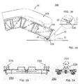
- Fig. 1 (A + B) shows a driving system structure 10, namely a truss 10A of an unfinished escalator with a balustrade 10B.
- the driving system structure 10 has a downwardly pointing foot or transport foot 20, which is accommodated in a foot receptacle 220.
- the foot 20 and the foot receptacle 200 essentially form a lifting system 20/220 according to the invention.
- the foot 20 and thus the adjacent to him area of the driving system structure 10th can be moved up and down in the direction of the arrows 0 and U relative to the foot receptacle 220.
- FIGS. 2A and 2B show two substantially identical lifting systems 20/20. 220, which are arranged as a pair, in Fig. 2B left and right, on a mobile receiving unit of a driving system transport device or a Fahrsystemetzillons 200.
- the foot 20 shown only in Fig. 1 (A + B) is wedge-shaped or round and has two opposite, downwardly tapering foot surfaces 22, which together include a foot angle W1. These tapered foot surfaces 22 are connected by two further, parallel, vertical foot surfaces.
- the foot can be cylindrical, round, spherical, spherical or prismatic.
- the space for the foot 20 is bounded laterally by the opposed wings 222 and, according to FIGS. 3A and 3D, by opposing side plates 224 which are arranged between the wings 222.
- the inclined foot surfaces 22 abut against the airfoils 222 and one of the vertical airfoils abuts a side plate 224 as long as the foot 20 is received in the foot receptacle 220.
- the inclined arrangement of the support surfaces 222 facilitates the sinking of the foot 20 into the foot receptacle 220, so that the support surfaces 222 in this case exert a centering effect.
- FIGS. 3A to 3D show details of the foot receptacle 220 of the lifting system 20/220.
- Figs. 3B and 3C show two wedge bodies 232 symmetrically arranged with respect to a vertical center plane.
- Each of the wedge bodies 232 has a wedge surface 230 as the upper boundary surface.
- the wings 222 include the angle W1. This angle W1 can also be enclosed by the foot surfaces 22.
- the wedge bodies 232 are formed and arranged symmetrically to a horizontal plane. They have an upper boundary surface or wedge surface 230, and they have a lower boundary surface 242.
- the wedge bodies 232 rest on sliding surfaces 252 of a base element 250.
- the sliding surfaces 252 are complementary, that is arranged with the same inclination angle to a horizontal plane as the lower boundary surfaces 242.
- a screw device 260 serves to move the wedge body 232 and thus the wedge surfaces 230 horizontally.
- the wedge surfaces 230 maintain their symmetrical arrangement relative to the vertical center plane, so that no lateral displacement of the foot 20 and thus the driving system structure 10 occurs.
- the wedge bodies 232 approach each other and the wedge surface 230 slides upwardly, with the downwardly tapered foot surfaces 22 on the wings 222 relative to each other making a rest or no movement in which the foot 20 and thus the ride system structure 10 are raised becomes. Accordingly, the lower boundary surfaces 242 and the sliding surfaces 252 of the base member 250 perform a sliding relative movement.
- the reverse sliding movements ie the wedge body 232 are removed from each other and the foot 20 is lowered down.
- Tension springs 270 are arranged laterally and serve to produce a uniform bias of the arrangement with the wedge bodies 232. In addition, the extension springs 270 facilitate the downward sliding of the wedge bodies 232 on the base 250.
- Both wedge surfaces 230 are to be made of a particularly slip-friendly material, with suitable materials for the wedge bodies 232 being, for example, brass or bronze or other coated materials having similar properties.
- the sliding surfaces must usually be lubricated with a suitable lubricant such as grease or lubricating oil.
- the driving system sensor 200 according to the invention is shown in FIGS. 2A to 2B.
- FIGS. 4A and 4B show an intermediate product 300 according to the invention with a driving system sensor and a driving system structure.
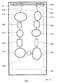
- Fig. 5 shows an assembly site 400 according to the invention, which is also apparent from this Fig. 5 of the method according to the invention.
- the mounting location is 400 during a transfer phase.
- the assembly site 400 includes a plurality of assembly stations 410 configured to perform station-specific, different assembly steps, wherein each assembly step may include substeps.
- the assembly station 410 also includes a plurality of driving system receivers 200 and a control system 430 that controls the operations in the assembly station 400 fully or partially automated.
- a hoist 420 such as a gantry crane or bridge crane, serves to lower the driving system structures 10 into the driving system receivers 200 and remove them from the driving system receivers. Further hoists are not necessary, so that the mounting location requires no complex building structures.
- a first drive system picker 200 shown at the top left in FIG. 5, is provided to receive a ride system structure 10. Further driving system receivers 200 have already picked up driving system structures 10 and together with them form intermediate products 300.
- the intermediates 300 are conveyed during the transfer phases by means of the autonomously movable driving system receivers 200 in the direction of the arrows to the individual assembly stations 410 or moved away therefrom.
- the intermediates 300 may be transferred both in their longitudinal and transverse directions, as between the assembly stations shown in FIG. 5, below.
- the intermediates 300 are stationary in the assembly stations 410.
- the driving system structure 200 is removed from the respectively finished intermediate product 300, which can be done with the help of the already mentioned hoist, as shown in Fig. 5 top right is shown.
- the control system 430 shown symbolically with dash-dotted lines, serves to control the entire process of complete assembly.
- the control system 430 may also include only parts of the mounting location, for example one or more or not all assembly stations.
Landscapes
- Engineering & Computer Science (AREA)
- Chemical & Material Sciences (AREA)
- Combustion & Propulsion (AREA)
- Transportation (AREA)
- Mechanical Engineering (AREA)
- Escalators And Moving Walkways (AREA)
- Automatic Assembly (AREA)
Abstract
Description
- Die Erfindung betrifft ein Hubsystem für eine Vertikaljustierung einer Fahrsystemstruktur, einen Fahrsystemaufnehmer mit einem Hubsystem, ein Zwischenprodukt für die Fertigungsmontage an einer Fahrsystemstruktur sowie einen Montagestandort und ein Montageverfahren für eine Fertigungsmontage an Fahrsystemstrukturen der Zwischenprodukte. Fertigungsmontage ist definiert als Zusammenbau von diversen Einzelteilen und Baugruppen einer Fahrtreppe bzw. eines Fahrsteiges.
- Hubsysteme im Sinne der Erfindung werden benutzt, um Fahrsystemstrukturen in Montagestationen niveaumässig auszurichten. Unter dem Begriff einer Fahrsystemstruktur soll ein Fahrsystem, das heisst eine Fahrtreppe oder ein Fahrsteig, in unfertigem Zustand während seiner werkseitigen Fertigungsmontage bzw. komplett Montage verstanden werden, wobei es sich zum Beispiel um einen Rahmen oder ein Fachwerk handeln kann, das während der Fertigungsmontage mit weiteren Elementen und Baugruppen bzw. Fertigungsteilen bestückt wird.
- Bei der Fertigungsmontage kann es von Bedeutung sein, dass die Fahrsystemstruktur genau horizontiert bzw. genauestens in der Waage ist.
- Ein Hubsystem, das bei der Fertigungsmontage von Fahrsystemstrukturen für eine Höhenjustierung verwendbar ist, kann zum Beispiel so ausgebildet sein, dass es mehrere Füsse aufweist, von denen jeder in einer Fussaufnahmen aufgenommen ist. Jeder Fuss stützt sich auf eine tragende Fläche auf. Um eine Höhenjustierung vorzunehmen, wird die tragende Fläche angehoben oder abgesenkt.
- Die hierbei hauptsächlich auftretenden Probleme sind die Folgenden:
- Erstens muss das Hubsystem eine möglichst perfekte Horizontrierung bzw. Höhenjustierung im Bereich von einigen Millimetern oder Zentimetern gewährleisten.
- Zweitens sind die Fahrsystemstrukturen sperrig und schwer, so dass an das Hubsystem hohe mechanische Anforderungen gestellt werden müssen.
- Drittens sollten die Hubsysteme rasch beschickbar und rasch und einfach zu bedienen sein. Die werkseitige Fertigungsmontage von Fahrsystemen kann nämlich stark rationalisiert werden, wenn sie in einer Fertigungsstrasse erfolgt. Eine solche Fertigungsstrasse umfasst mehrere Montagestationen, die von den Fahrsystemstrukturen nacheinander durchlaufen werden und gleichzeitig beschickt werden. In jeder Montagestation werden während einer Montagephase stationsspezifische Montageschritte durchgeführt. Nach Beendigung der möglichst synchron durchgeführten Montagephase werden die Fahrsystemstrukturen während einer Transportphase zur jeweils folgenden Montagestation gebracht, wobei unter optimalen Fabrikationsbedingungen auch der Transport aller Fahrsystemstrukturen möglichst synchron vor sich gehen sollte. Es ist offensichtlich, dass eine rasche Beschickung und Bedienung der Hubsysteme die Manipulationszeiten stark verkürzt.
- Viertens sollen die Hubsysteme preisgünstig sein, da eine Vielzahl von ihnen, nämlich mehrere Hubsysteme für jede Montagestation, benötigt werden.
- Zwar ist aus der
US-3,724,015 eine einstellbare Treppe in der Art einer Gangway zur Benutzung auf Flughäfen bekannt. Hierbei handelt es sich aber nicht um eine Treppe in Fertigungsmontage, und ausserdem sind die geforderten Genauigkeiten bedeutend geringer als es bei der Fertigungsmontage von Fahrsystemen erforderlich ist.
Ein Hubsystem, mit welchem die weiter oben erwähnten Probleme gelöst werden können, ist nicht bekannt.
Die Aufgabe der Erfindung wird somit darin gesehen, - ein Hubsystem zu schaffen, das sich für den Einsatz bei der Fertigungsmontage von Fahrsystemstrukturen eignet,
- einen Fahrsystemaufnehmer mit einem solchen Hubsystem vorzuschlagen,
- ein Zwischenprodukt, umfassend einen solchen Fahrsystemaufnehmer und eine Fahrsystemstruktur, vorzuschlagen,
- einen Montagestandort für Fertigungsmontage an einem solchen Zwischenprodukt bzw. an der Fahrsystemstruktur des Zwischenproduktes und
- ein Verfahren zur Durchführung einer derartigen Fertigungsmontage vorzuschlagen.
- Die Lösung dieser Aufgabe erfolgt erfindungsgemäss
- für das Hubsystem durch die Merkmale des Patentanspruchs 1,
- für den Fahrsystemaufnehmer durch die Merkmale des Patentanspruchs 11,
- für das Zwischenprodukt durch die Merkmale des Patentanspruchs 12,
- für den Montagestandort durch die Merkmale des Patentanspruchs 13, und
- für das Montageverfahren durch die Merkmale des Patentanspruchs 14.
- Vorteilhafte Weiterbildungen des erfindungsgemässen Hubsystems sind durch die abhängigen Patentansprüche definiert.
Das neue Hubsystem umfasst einen Fuss, der mindestens während der Zusammenbauphase starr am Fahrsystem abgebracht ist und während der Fertigungsmontage nach unten weist, sowie eine Fussaufnahme, in welcher der Fuss aufnehmbar bzw. in den Montagestationen aufgenommen ist. Der Fuss kann zylindrisch, rund, kugelig, ballig oder prismatisch sein. Dieser Fuss kann beispielsweise an gegenüberliegenden Seiten durch zwei Fussflächen begrenzt werden, die unter einem Fussflächenwinkel zueinander angeordnet sind. Der Fuss kann also in einem Vertikalschnitt prismatisch sein. Die Fussaufnahme weist in diesem Fall zwei Tragflächen auf, an denen die Fussflächen anliegen. Diese Tragflächen sind komplementär zu den Fussflächen, nämlich ebenfalls prismatisch, ausgebildet und angeordnet. Die Tragflächen sind vertikal verschiebbar. Bei der Verschiebung der Tragflächen ändert der Fuss seine absolute Höhenlage, wodurch die Vertikaljustierung erfolgt.
Um bei der Höhenjustierung eine seitliche Verschiebung einer vertikalen Fussachse zu vermeiden, ist es vorteilhaft, wenn die beiden Tragflächen der Fussaufnahme spiegelsymmetrisch zu einer Vertikalmittelebene angeordnet und relativ zu dieser Vertikalmittelebene horizontal verschiebbar sind. - Bei einer vorteilhaften Ausbildung des Hubsystems bildet die Tragfläche eine obere Begrenzungsfläche eines Keilelementes. Dieses Keilelement besitzt eine untere Begrenzungsfläche, mit der es auf einer Gleitfläche eines Grundkörpers verschiebbar abgestützt ist.
- Die untere Begrenzungsfläche des Keilkörpers steht vorteilhaft unter einem Keilwinkel zu einer Horizontalebene, so dass die obere Begrenzungsfläche und die untere Begrenzungsfläche des Keilkörpers spiegelsymmetrisch zu einer Horizontalebene gerichtet sind.
- Zur Verschiebung der Tragflächen bzw. der Keilkörper kann das Hubsystem eine mechanische Anordnung, insbesondere eine Schraubenanordnung aufweisen.
- Die Schraubenanordnung kann zum Beispiel eine Zentralschraube aufweisen, und diese kann mittels eines Gabel-, Ring- oder Steckschlüssels oder eines elektrisch oder hydraulisch oder per Pressluft betätigbaren Schlüssels betätigbar sein bzw. betrieben werden.
- Im Weiteren kann das Hubsystem eine Federanordnung aufweisen, um die Tragflächen der Fussaufnahme auf den Fuss vorzuspannen und die Betätigung des Hubsystems zu erleichtern.
- Um den Fuss sicher in der Fussaufnahme zu halten, kann die Fussaufnahme zwei einander gegenüberliegende vertikale Seitenplatten besitzt, die zusammen mit den Tragflächen einen Raum für den Fuss begrenzen.
- Das Hubsystem weist üblicherweise weitere Füsse und Fussaufnahmen, insgesamt zum Beispiel drei oder vier Füsse und Fussaufnahmen auf.
- Weitere Einzelheiten und Vorteile der Erfindung werden im Folgenden an Hand eines Beispieles und mit Bezug auf die Zeichnungen beschrieben. Es zeigen:
- Fig. 1A
- ein Zwischenprodukt, umfassend ein stationäres Hubsystem mit einem Bereich einer auf ihm abgestützten Fahrtreppe, von der Seite;
- Fig. 1B
- den in Fig. 1A eingekreisten Bereich, in gegenüber Fig. 1A vergrösserter Darstellung;
- Fig. 2A
- einen Fahrsystemaufnehmer mit zwei Hubsystemen, von denen nur eines sichtbar ist, wobei das Hubsystem auf einer mobilen Aufnahmeeinheit des Fahrsystemaufnehmers angeordnet ist, von der Seite;
- Fig. 2B
- die in Fig. 2A dargestellten, auf der Aufnahmeeinheit des Fahrsystemaufnehmers angebrachten Hubsysteme, von vorne;
- Fig. 3A
- ein Hubsystem nach der Erfindung in einer oberen Lage, von vorne;
- Fig. 3B
- das in Fig. 3A gezeigte Hubsystem in der oberen Lage, von der Seite;
- Fig. 3C
- das in den Fig. 3A und 3B gezeigte Hubsystem in einer unteren Lage, von der Seite;
- Fig. 3D
- das in den Fig. 3A bis 3C gezeigte Hubsystem in der unteren Lage, von vorne;
- Fig. 4A
- ein Zwischenprodukt nach der Erfindung;
- Fig. 4B
- den in Fig. 4A eingekreisten Bereich in gegenüber Fig. 4A vergrösserter Darstellung; und
- Fig. 5
- einen Montagestandort nach der Erfindung.
- Fig. 1 (A+B) zeigt eine Fahrsystemstruktur 10, nämlich ein Fachwerk 10A einer noch unfertigen Fahrtreppe mit einer Balustrade 10B. Die Fahrsystemstruktur 10 besitzt einen nach unten weisenden Fuss bzw. Transportfuss 20, der in einer Fussaufnahme 220 aufgenommen ist. Der Fuss 20 und die Fussaufnahme 200 bilden im Wesentlichen ein Hubsystem 20/220 nach der Erfindung. Der Fuss 20 und damit der an ihn grenzende Bereich der Fahrsystemstruktur 10 können in Richtung der Pfeile 0 und U relativ zur Fussaufnahme 220 aufwärts und abwärts bewegt werden.
- Während das in Fig. 1 (A+B) gezeigte Hubsystem 20/220 stationär ist und sich beispielsweise an einer nicht genau dargestellten Montagestation 410 eines Montagestandortes 400 befinden kann, zeigen die Fig. 2A und Fig. 2B zwei im Wesentlichen gleiche Hubsysteme 20/220, die als Paar, in Fig. 2B links und rechts, auf einer mobilen Aufnahmeeinheit einer Fahrsystemtransporteinrichtung bzw. eines Fahrsystemaufnehmers 200 angeordnet sind.
- Der nur in Fig. 1 (A+B) gezeigte Fuss 20 ist keilförmig oder rund ausgebildet und weist zwei sich gegenüberliegende, nach unten zulaufende Fussflächen 22 auf, die zusammen einen Fusswinkel W1 einschliessen. Diese zulaufenden Fussflächen 22 sind durch zwei weitere, parallele, vertikale Fussflächen verbunden. Der Fuss kann zylindrisch, rund, kugelig, ballig oder prismatisch sein.
Der Raum für den Fuss 20 ist seitlich durch die einander gegenüberstehenden Tragflächen 222 und gemäss Fig. 3A und Fig. 3D durch einander gegenüberstehende Seitenplatten 224 begrenzt, welche zwischen den Tragflächen 222 angeordnet sind. Die geneigten Fussflächen 22 liegen an den Tragflächen 222 an, und eine der vertikalen Fussflächen liegt an einer Seitenplatte 224 an, solange, als der Fuss 20 in der Fussaufnahme aufgenommen 220 ist. - Durch die geneigte Anordnung der Tragflächen 222 wird das Einsenken des Fusses 20 in die Fussaufnahme 220 erleichtert, so dass die Tragflächen 222 hierbei eine zentrierende Wirkung ausüben.
- Die Fig. 3A bis 3D zeigen Einzelheiten der Fussaufnahme 220 des Hubsystems 20/220. Insbesondere zeigen die Fig. 3B und 3C zwei Keilkörper 232, die bezüglich einer Vertikalmittelebene symmetrisch angeordnet sind. Jeder der Keilkörper 232 weist als obere Begrenzungsfläche eine Keilfläche 230 auf. An den Tragflächen 222 kommen die komplementär geformten bzw. rund, ballig oder bombiert bzw. tonnig geformten und angeordneten Fussflächen 22 des Fusses 20 zur Anlage. Die Tragflächen 222 schliessen den Winkel W1 ein. Dieser Winkel W1 kann auch von den Fussflächen 22 umschlossen werden. Die Keilkörper 232 sind symmetrisch zu einer Horizontalebene ausgebildet und angeordnet. Sie weisen eine obere Begrenzungsfläche bzw. Keilfläche 230 auf, und sie weisen eine untere Begrenzungsfläche 242 auf. Die Keilkörper 232 liegen auf Gleitflächen 252 eines Grundelementes 250 auf. Die Gleitflächen 252 sind komplementär, das heisst mit dem gleichen Neigungswinkel zu einer Horizontalebene wie die unteren Begrenzungsflächen 242, angeordnet.
- Eine Schraubenvorrichtung 260, bzw. im vorliegenden Fall eine einzige Zentralschraube, dient dazu, die Keilkörper 232 und damit die Keilflächen 230 horizontal zu verschieben. Hierbei behalten die Keilflächen 230 ihre symmetrische Anordnung relativ zur Vertikalmittelebene bei, so dass keine seitliche Verschiebung des Fusses 20 und damit der Fahrsystemstruktur 10 eintritt.
- Beim Anziehen der Schraubenvorrichtung 260 nähern sich die Keilkörper 232 einander und die Keilfläche 230 gleitet aufwärts, wobei die nach unten zulaufenden Fussflächen 22 auf den Tragflächen 222 relativ zueinander eine ruhende oder keine Bewegung ausführt, bei welcher der Fuss 20 und somit die Fahrsystemstruktur 10 angehoben wird. Entsprechend führen auch die unteren Begrenzungsflächen 242 und die Gleitflächen 252 des Grundelementes 250 eine gleitende Relativbewegung durch. Beim Lockern der Schraubenvorrichtung 260 erfolgen die umgekehrten Gleitbewegungen, das heisst die Keilkörper 232 entfernen sich voneinander und der Fuss 20 senkt sich nach unten ab.
- Zugfedern 270 sind seitlich angeordnet und dienen dazu, eine gleichmässige Vorspannung der Anordnung mit den Keilkörpern 232 zu erzeugen. Ausserdem erleichtern die Zugfedern 270 das Abwärtsgleiten der Keilkörper 232 am Grundelement 250.
- Beide Keilflächen 230 sind aus einem besonders gleitfreundlichen Material herzustellen, wobei sich als geeignetes Material für die Keilkörper 232 zum Beispiel Messing oder Bronze oder andere, beschichtete Materialien mit ähnlichen Eigenschaften erwiesen haben.
- Die aneinander gleitenden Flächen müssen üblicherweise mit einem geeigneten Schmiermittel wie Schmierfett oder Schmieröl geschmiert werden.
- Der Fahrsystemaufnehmer 200 nach der Erfindung ist in den Fig. 2A bis 2B dargestellt.
- Die Fig. 4A und Fig. 4B zeigen ein Zwischenprodukt 300 nach der Erfindung, mit einem Fahrsystemaufnehmer und einer Fahrsystemstruktur.
- Fig. 5 zeigt einen Montagestandort 400 nach der Erfindung, wobei aus dieser Fig. 5 auch des Verfahren nach der Erfindung ersichtlich ist. Der Montagestandort 400 ist während einer Transferphase dargestellt. Der Montagestandort 400 umfasst mehrere Montagestationen 410, die dazu ausgelegt sind, stationsspezifische unterschiedliche Montageschritte durchzuführen, wobei jeder Montageschritt Teilschritte umfassen kann. Zur Montagestation 410 gehören ebenfalls eine Vielzahl von Fahrsystemaufnehmern 200 und ein Steuersystem 430, das die Vorgänge in der Montagestation 400 vollständig oder teilweise automatisiert steuert. Ein Hebezeug 420, beispielsweise ein Portalkran oder Brückenkran, dient dazu, die Fahrsystemstrukturen 10 in die Fahrsystemaufnehmer 200 einzusenken und sie wieder aus den Fahrsystemaufnehmern zu entfernen. Weitere Hebezeuge sind nicht notwendig, so dass der Montagestandort keiner aufwändigen Gebäudestrukturen bedarf.
- Ein erster Fahrsystemaufnehmer 200, in Fig. 5 links oben gezeigt, ist bereitgestellt, um eine Fahrsystemstruktur 10 aufzunehmen. Weitere Fahrsystemaufnehmer 200 haben bereits Fahrsystemstrukturen 10 aufgenommen und bilden mit diesen zusammen Zwischenprodukte 300. Die Zwischenprodukte 300 werden während der Transferphasen mittels der autonom beweglichen Fahrsystemaufnehmer 200 in Richtung der Pfeile den einzelnen Montagestationen 410 zugeführt bzw. aus diesen wegbewegt. Die Zwischenprodukte 300 können sowohl in ihrer Längsrichtung wie auch quer dazu, wie zwischen den in Fig. 5 unten gezeigten Montagestationen, transferiert werden. Während der Montagephasen befinden sich die Zwischenprodukte 300 stationär in den Montagestationen 410. Nach Beendigung der kompletten Montage wird aus dem jeweils fertig bearbeitete Zwischenprodukt 300 die Fahrsystemstruktur 200 entfernt, was mit Hilfe des schon erwähnten Hebezeuges geschehen kann, wie es in Fig. 5 oben rechts dargestellt ist. Das Steuersystem 430, symbolisch dargestellt mit strichpunktierten Linien, dient dazu, den gesamten Ablauf der kompletten Montage zu steuern. Das Steuersystem 430 kann auch nur Teile des Montagestandortes, zum Beispiel eine oder mehrere bzw. nicht alle Montagestationen, einbeziehen.
Claims (14)
- Hubsystem (20/220) für eine Vertikaljustierung einer Fahrsystemstruktur (10), mit einem bei einer Montage der Fahrsystemstruktur (10) nach unten weisenden Fuss bzw. Positionierstück (20) an der Fahrsystemstruktur (10) und einer Fussaufnahme bzw. Aufnahme (220), dadurch gekennzeichnet, dass der Fuss (20) mindestens eine Fussfläche bzw. Positionierstückfläche (22) aufweist, die an mindestens einer Tragfläche (222) der Fussaufnahme (220) anliegt, die Tragfläche (222) komplementär zu der Fussfläche (22) angeordnet ist, und die Tragfläche (222) vertikal verschiebbar ist, wobei die Fahrsystemstruktur (10) ihre Höhenlage verändert und dadurch die Vertikaljustierung erfolgt.
- Hubsystem (20/220) nach Patentanspruch 1, dadurch gekennzeichnet, dass die Fussaufnahme (220) zwei Tragflächen (222)aufweist und dass die beiden Tragflächen (222) der Fussaufnahme (220) spiegelsymmetrisch zu einer Vertikalmittelebene angeordnet und relativ zu dieser Vertikalmittelebene vertikal verschiebbar sind.
- Hubsystem (20/220) nach Patentanspruch 1, dadurch gekennzeichnet, dass die Fussaufnahme (220) mindestens ein Keilelement (232) aufweist, welches eine untere Begrenzungsfläche (242) aufweist, mit der es auf einer Gleitfläche (252) eines Grundelementes (250) verschiebbar abgestützt ist.
- Hubsystem (20/220) nach Patentanspruch 3, dadurch gekennzeichnet, dass das Keilkörper eine obere Begrenzungsfläche bzw. Keilfläche (230) aufweist, die unter einem Keilwinkel (κ) zu einer Horizontalebene (H) angeordnet ist, derart, dass die obere Begrenzungsfläche (230) und die untere Begrenzungsfläche (242) des Keilkörpers (232) spiegelsymmetrisch zu der Horizontalebene angeordnet sind.
- Hubsystem (20/220) nach einem der vorangehenden Patentansprüche, dadurch gekennzeichnet, dass sie eine Schraubenanordnung (260) aufweist, mittels welcher die Keilfläche (230) horizontal verschiebbar ist.
- Hubsystem (20/220) nach Patentanspruch 5, dadurch gekennzeichnet, dass die Schraubenanordnung (260) eine Zentralschraube aufweist, die mittels eines Schlüssels oder eines elektrisch oder hydraulisch oder per Pressluft betätigbaren Schlüssels betätigbar ist.
- Hubsystem (20/220) nach einem der vorangehenden Patentansprüche, dadurch gekennzeichnet, dass es eine Federanordnung (270) aufweist, mittels welcher die Tragflächen (222) der Fussaufnahme (220) in vertikaler Richtung vorgespannt sind.
- Hubsystem (20/220) nach einem der vorangehenden Patentansprüche, dadurch gekennzeichnet, dass die Fussaufnahme (220) zwei einander gegenüberliegende Seitenplatten (224) besitzt, die zusammen mit den Tragflächen (222) einen Raum für den Fuss (20) begrenzen.
- Hubsystem (20/220) nach einem der vorangehenden Patentansprüche, dadurch gekennzeichnet, dass der Fuss (20) so ausgebildet und angeordnet ist, dass er von einer Fussaufnahme (220) einer Aufnahmeeinheit eines Fahrsystemaufnehmers (200) aufnehmbar ist, um als Transportfuss zu dienen.
- Hubsystem (20/220) nach einem vorangehenden Patentansprüche, dadurch gekennzeichnet, dass es, vorzugsweise ein, zwei oder drei, weitere Füsse (20) und Fussaufnahmen (220) besitzt.
- Fahrsystemaufnehmer (200) zur Aufnahme einer Fahrsystemstruktur (10), dadurch gekennzeichnet, dass er mindestens eine Fussaufnahme (220) zum Aufnehmen eines Fusses (20) der Fahrsystemstruktur (10) aufweist.
- Zwischenprodukt (300), umfassend einen Fahrsystemaufnehmer (200) und eine Fahrsystemstruktur (10), dadurch gekennzeichnet, dass die Fahrsystemstruktur (10) mindestens einen Fuss (20) aufweist, der in Fussaufnahmen (220) des Fahrsystemaufnehmers (200) aufgenommen ist, um alternativ entweder horizontale und abwärts gerichtete vertikale Bewegungen der Fahrsystemstruktur (10) relativ zum Fahrsystemaufnehmer (200) zu verhindern oder ein Hubsystem (20/220) zu bilden, um die vertikale Lage der Fahrsystemstruktur (10) relativ zum Fahrsystemaufnehmer (200) zu justieren.
- Montagestandort (400) für ein Vormontieren und/oder Fertigungsmontieren von Fahrsystemen, mit einer Reihe von Montagestationen (410), von denen jede zur Durchführung eines stationsspezifischen Montageschrittes an einer Fahrsystemstruktur (10) eines Fahrsystems befähigt ist, mit mehreren Fahrsystemaufnehmern (200), von denen mindestens einige jeweils zusammen mit einer Fahrsystemstruktur (10) Zwischenprodukte (300) bilden, und mit einem Steuersystem (430), um gleichzeitig und getaktet die Zwischenprodukte (300) in je eine der Montagestationen (410) zu transferieren, die Fahrsystemstrukturen (10) der Zwischenprodukte (300) in den jeweiligen Montagestationen (410) zu montieren bzw. fertigzumontieren, und anschliessend die Zwischenprodukte (300) in die jeweils nachfolgende Montagestation (410) zu transferieren, wobei der Montagestandort (400) vorzugsweise mindestens ein Hebezeug (420), beispielsweise einen Kran, aufweist, um die Fahrsystemstrukturen (10) auf die Fahrsystemaufnehmer (200) zu bringen und sie daraus zu entfernen.
- Verfahren zum Montieren und/oder Fertigungsmontieren von Fahrsystemen, wobei aus je einer Fahrsystemstruktur (10) eines Fahrsystems und je einem Fahrsystemaufnehmer (200) ein Zwischenprodukt (300) gebildet wird, die Zwischenprodukte (300) aufeinanderfolgend, getaktet und gleichzeitig, einen Montagestandort (400) durchlaufen, wobei während den Transferphasen jedes der Zwischenprodukte (300) zwischen je einer der Montagestationen (410) und der darauffolgenden Montagestation (410) transferiert wird, und während den Montagephasen in der jeweiligen Montagestationen (410) ein stationsspezifischer Montageschritte an den Fahrsystemstrukturen (10) der Zwischenprodukte (300) durchgeführt wird, und wobei vorzugsweise ein Steuersystem (430) des Montagestandortes (400) die Montagephasen und/oder die Transferphasen zeitlich jeweils mindestens annähernd gleich hält und den Transfer der Zwischenprodukte (300) steuert.
Priority Applications (2)
| Application Number | Priority Date | Filing Date | Title |
|---|---|---|---|
| PL06125373T PL1795489T3 (pl) | 2005-12-07 | 2006-12-05 | System podnoszący |
| EP06125373A EP1795489B1 (de) | 2005-12-07 | 2006-12-05 | Hubsystem. |
Applications Claiming Priority (3)
| Application Number | Priority Date | Filing Date | Title |
|---|---|---|---|
| EP05111810 | 2005-12-07 | ||
| EP06112650 | 2006-04-13 | ||
| EP06125373A EP1795489B1 (de) | 2005-12-07 | 2006-12-05 | Hubsystem. |
Publications (2)
| Publication Number | Publication Date |
|---|---|
| EP1795489A1 true EP1795489A1 (de) | 2007-06-13 |
| EP1795489B1 EP1795489B1 (de) | 2010-09-22 |
Family
ID=37887983
Family Applications (1)
| Application Number | Title | Priority Date | Filing Date |
|---|---|---|---|
| EP06125373A Not-in-force EP1795489B1 (de) | 2005-12-07 | 2006-12-05 | Hubsystem. |
Country Status (2)
| Country | Link |
|---|---|
| EP (1) | EP1795489B1 (de) |
| PL (1) | PL1795489T3 (de) |
Cited By (1)
| Publication number | Priority date | Publication date | Assignee | Title |
|---|---|---|---|---|
| US9440820B2 (en) | 2015-01-09 | 2016-09-13 | Kone Coporation | Escalator lifting frame and method of using the same |
Families Citing this family (2)
| Publication number | Priority date | Publication date | Assignee | Title |
|---|---|---|---|---|
| PL3426589T3 (pl) | 2016-03-10 | 2020-09-07 | Inventio Ag | Sposób wspomaganego robotem wytwarzania konstrukcji nośnej dla instalacji do transportu osób |
| WO2017153314A1 (de) | 2016-03-10 | 2017-09-14 | Inventio Ag | Vorrichtung zum roboterunterstützten herstellen eines tragwerkes für eine personentransportanlage |
Citations (5)
| Publication number | Priority date | Publication date | Assignee | Title |
|---|---|---|---|---|
| US3137512A (en) * | 1961-08-11 | 1964-06-16 | Carpezzi Leo Joseph | Height adjustable dolly |
| JPH07315740A (ja) * | 1994-05-24 | 1995-12-05 | Hitachi Building Syst Eng & Service Co Ltd | エスカレータトラスの搬出方法 |
| JPH11199165A (ja) * | 1998-01-14 | 1999-07-27 | Hitachi Building Systems Co Ltd | エスカレータフレームの階段移動方法 |
| GB2352692A (en) * | 1999-08-03 | 2001-02-07 | Honda Canada Inc | An assembly line system |
| DE10041578A1 (de) * | 2000-08-24 | 2002-03-21 | Markus Helling | Fahrwerksystem |
-
2006
- 2006-12-05 PL PL06125373T patent/PL1795489T3/pl unknown
- 2006-12-05 EP EP06125373A patent/EP1795489B1/de not_active Not-in-force
Patent Citations (5)
| Publication number | Priority date | Publication date | Assignee | Title |
|---|---|---|---|---|
| US3137512A (en) * | 1961-08-11 | 1964-06-16 | Carpezzi Leo Joseph | Height adjustable dolly |
| JPH07315740A (ja) * | 1994-05-24 | 1995-12-05 | Hitachi Building Syst Eng & Service Co Ltd | エスカレータトラスの搬出方法 |
| JPH11199165A (ja) * | 1998-01-14 | 1999-07-27 | Hitachi Building Systems Co Ltd | エスカレータフレームの階段移動方法 |
| GB2352692A (en) * | 1999-08-03 | 2001-02-07 | Honda Canada Inc | An assembly line system |
| DE10041578A1 (de) * | 2000-08-24 | 2002-03-21 | Markus Helling | Fahrwerksystem |
Cited By (1)
| Publication number | Priority date | Publication date | Assignee | Title |
|---|---|---|---|---|
| US9440820B2 (en) | 2015-01-09 | 2016-09-13 | Kone Coporation | Escalator lifting frame and method of using the same |
Also Published As
| Publication number | Publication date |
|---|---|
| EP1795489B1 (de) | 2010-09-22 |
| PL1795489T3 (pl) | 2011-03-31 |
Similar Documents
| Publication | Publication Date | Title |
|---|---|---|
| EP2792431B1 (de) | Bearbeitungsanlage für Flugzeugstrukturbauteile | |
| DE102007054034B4 (de) | Verfahren und Vorrichtung zum Wenden von plattenförmigen Körpern | |
| DE69321786T2 (de) | Fahrzeugkran mit Vorrichtung zum Anbringen des Gegengewichtes | |
| DE102016104559A1 (de) | Anordnung, durch welche während der Herstellung einer Vorrichtung lose zusammengefügte Einzelteile der Vorrichtung in ihre bestimmungsgemäße Relativlage bringbar sind | |
| DE3316050C2 (de) | ||
| EP2524861B1 (de) | Vorrichtung und Verfahren zur Handhabung eines Fahrzeugmontagewerkzeugträgers bei einer Fahrzeugfertigungslinie, Fahrzeugmontagewerkzeugträger und Montagestation | |
| WO2012153232A2 (de) | Substrattransportmodul, belade- und entladesystem und transportverfahren für substrate in einer substratbearbeitungsanlage | |
| DE202016101389U1 (de) | Anordnung, durch welche während der Herstellung einer Vorrichtung lose zusammengefügte Einzelteile der Vorrichtung in ihre bestimmungsgemäße Relativlage bringbar sind | |
| EP1795489B1 (de) | Hubsystem. | |
| DE1808989C3 (de) | Vorrichtung zum Herstellen von monolithischen, mit einer offenen Seite nach unten weisenden Stahlbetonraumzellen, insbesondere Fertiggaragen, unter Flur | |
| EP3609775A1 (de) | Fertigungsanlage mit fahrerlosen transportfahrzeugen und verbesserter werkstückpositionierung in den fertigungsstationen | |
| EP1702692B1 (de) | Bördelvorrichtung | |
| DE3429283C2 (de) | Verfahren und Vorrichtung zum Austauschen von abgenutzten Elektrolysierzellen | |
| EP4105160B1 (de) | Haltevorrichtung | |
| DE2748709A1 (de) | Walzenstaender | |
| EP0296151B1 (de) | Vorrichtung mit einem hubgestell zum bearbeiten von werkstücken | |
| CH665378A5 (de) | Vorrichtung zum exakten positionieren eines werkstuecks. | |
| EP1558409B1 (de) | Walzwerk mit supportplatten | |
| EP1795488B1 (de) | Fahrsystemaufnehmer. | |
| DE102007049673A1 (de) | Verfahren zum Bergen von Flugzeugen und Flugzeugbergeheber | |
| DE19900688A1 (de) | Krananlage | |
| EP2921563A1 (de) | Vorrichtung zum vertikalen Anheben und/oder Absenken eines metallurgischen Gefäßes, Anlage mit einer solchen Vorrichtung und Verfahren | |
| EP4383975B1 (de) | Bauteilmagazin und anlage zur montage von bauteilen auf einer tragschiene | |
| DE3144927A1 (de) | Flurfoerdergeraet | |
| WO2019161915A1 (de) | Flächenportal |
Legal Events
| Date | Code | Title | Description |
|---|---|---|---|
| PUAI | Public reference made under article 153(3) epc to a published international application that has entered the european phase |
Free format text: ORIGINAL CODE: 0009012 |
|
| AK | Designated contracting states |
Kind code of ref document: A1 Designated state(s): AT BE BG CH CY CZ DE DK EE ES FI FR GB GR HU IE IS IT LI LT LU LV MC NL PL PT RO SE SI SK TR |
|
| AX | Request for extension of the european patent |
Extension state: AL BA HR MK YU |
|
| 17P | Request for examination filed |
Effective date: 20071211 |
|
| AKX | Designation fees paid |
Designated state(s): AT BE BG CH CY CZ DE DK EE ES FI FR GB GR HU IE IS IT LI LT LU LV MC NL PL PT RO SE SI SK TR |
|
| 17Q | First examination report despatched |
Effective date: 20080225 |
|
| REG | Reference to a national code |
Ref country code: HK Ref legal event code: DE Ref document number: 1107688 Country of ref document: HK |
|
| GRAP | Despatch of communication of intention to grant a patent |
Free format text: ORIGINAL CODE: EPIDOSNIGR1 |
|
| GRAS | Grant fee paid |
Free format text: ORIGINAL CODE: EPIDOSNIGR3 |
|
| GRAA | (expected) grant |
Free format text: ORIGINAL CODE: 0009210 |
|
| AK | Designated contracting states |
Kind code of ref document: B1 Designated state(s): AT BE BG CH CY CZ DE DK EE ES FI FR GB GR HU IE IS IT LI LT LU LV MC NL PL PT RO SE SI SK TR |
|
| REG | Reference to a national code |
Ref country code: GB Ref legal event code: FG4D Free format text: NOT ENGLISH |
|
| REG | Reference to a national code |
Ref country code: CH Ref legal event code: EP |
|
| REG | Reference to a national code |
Ref country code: IE Ref legal event code: FG4D Free format text: LANGUAGE OF EP DOCUMENT: GERMAN |
|
| REF | Corresponds to: |
Ref document number: 502006007918 Country of ref document: DE Date of ref document: 20101104 Kind code of ref document: P |
|
| REG | Reference to a national code |
Ref country code: RO Ref legal event code: EPE |
|
| REG | Reference to a national code |
Ref country code: NL Ref legal event code: T3 |
|
| REG | Reference to a national code |
Ref country code: HK Ref legal event code: GR Ref document number: 1107688 Country of ref document: HK |
|
| PG25 | Lapsed in a contracting state [announced via postgrant information from national office to epo] |
Ref country code: LT Free format text: LAPSE BECAUSE OF FAILURE TO SUBMIT A TRANSLATION OF THE DESCRIPTION OR TO PAY THE FEE WITHIN THE PRESCRIBED TIME-LIMIT Effective date: 20100922 |
|
| REG | Reference to a national code |
Ref country code: ES Ref legal event code: FG2A Effective date: 20110214 |
|
| LTIE | Lt: invalidation of european patent or patent extension |
Effective date: 20100922 |
|
| PG25 | Lapsed in a contracting state [announced via postgrant information from national office to epo] |
Ref country code: SI Free format text: LAPSE BECAUSE OF FAILURE TO SUBMIT A TRANSLATION OF THE DESCRIPTION OR TO PAY THE FEE WITHIN THE PRESCRIBED TIME-LIMIT Effective date: 20100922 |
|
| PG25 | Lapsed in a contracting state [announced via postgrant information from national office to epo] |
Ref country code: LV Free format text: LAPSE BECAUSE OF FAILURE TO SUBMIT A TRANSLATION OF THE DESCRIPTION OR TO PAY THE FEE WITHIN THE PRESCRIBED TIME-LIMIT Effective date: 20100922 Ref country code: GR Free format text: LAPSE BECAUSE OF FAILURE TO SUBMIT A TRANSLATION OF THE DESCRIPTION OR TO PAY THE FEE WITHIN THE PRESCRIBED TIME-LIMIT Effective date: 20101223 Ref country code: SE Free format text: LAPSE BECAUSE OF FAILURE TO SUBMIT A TRANSLATION OF THE DESCRIPTION OR TO PAY THE FEE WITHIN THE PRESCRIBED TIME-LIMIT Effective date: 20100922 |
|
| REG | Reference to a national code |
Ref country code: PL Ref legal event code: T3 |
|
| REG | Reference to a national code |
Ref country code: SK Ref legal event code: T3 Ref document number: E 8451 Country of ref document: SK |
|
| REG | Reference to a national code |
Ref country code: IE Ref legal event code: FD4D |
|
| PG25 | Lapsed in a contracting state [announced via postgrant information from national office to epo] |
Ref country code: IE Free format text: LAPSE BECAUSE OF FAILURE TO SUBMIT A TRANSLATION OF THE DESCRIPTION OR TO PAY THE FEE WITHIN THE PRESCRIBED TIME-LIMIT Effective date: 20100922 |
|
| PG25 | Lapsed in a contracting state [announced via postgrant information from national office to epo] |
Ref country code: PT Free format text: LAPSE BECAUSE OF FAILURE TO SUBMIT A TRANSLATION OF THE DESCRIPTION OR TO PAY THE FEE WITHIN THE PRESCRIBED TIME-LIMIT Effective date: 20110124 Ref country code: IS Free format text: LAPSE BECAUSE OF FAILURE TO SUBMIT A TRANSLATION OF THE DESCRIPTION OR TO PAY THE FEE WITHIN THE PRESCRIBED TIME-LIMIT Effective date: 20110122 Ref country code: EE Free format text: LAPSE BECAUSE OF FAILURE TO SUBMIT A TRANSLATION OF THE DESCRIPTION OR TO PAY THE FEE WITHIN THE PRESCRIBED TIME-LIMIT Effective date: 20100922 |
|
| BERE | Be: lapsed |
Owner name: INVENTIO A.G. Effective date: 20101231 |
|
| PG25 | Lapsed in a contracting state [announced via postgrant information from national office to epo] |
Ref country code: MC Free format text: LAPSE BECAUSE OF NON-PAYMENT OF DUE FEES Effective date: 20101231 |
|
| PLBE | No opposition filed within time limit |
Free format text: ORIGINAL CODE: 0009261 |
|
| STAA | Information on the status of an ep patent application or granted ep patent |
Free format text: STATUS: NO OPPOSITION FILED WITHIN TIME LIMIT |
|
| 26N | No opposition filed |
Effective date: 20110623 |
|
| PG25 | Lapsed in a contracting state [announced via postgrant information from national office to epo] |
Ref country code: DK Free format text: LAPSE BECAUSE OF FAILURE TO SUBMIT A TRANSLATION OF THE DESCRIPTION OR TO PAY THE FEE WITHIN THE PRESCRIBED TIME-LIMIT Effective date: 20100922 |
|
| PG25 | Lapsed in a contracting state [announced via postgrant information from national office to epo] |
Ref country code: BE Free format text: LAPSE BECAUSE OF NON-PAYMENT OF DUE FEES Effective date: 20101231 |
|
| REG | Reference to a national code |
Ref country code: DE Ref legal event code: R097 Ref document number: 502006007918 Country of ref document: DE Effective date: 20110623 |
|
| PGFP | Annual fee paid to national office [announced via postgrant information from national office to epo] |
Ref country code: NL Payment date: 20111228 Year of fee payment: 6 |
|
| PG25 | Lapsed in a contracting state [announced via postgrant information from national office to epo] |
Ref country code: CY Free format text: LAPSE BECAUSE OF FAILURE TO SUBMIT A TRANSLATION OF THE DESCRIPTION OR TO PAY THE FEE WITHIN THE PRESCRIBED TIME-LIMIT Effective date: 20100922 |
|
| PG25 | Lapsed in a contracting state [announced via postgrant information from national office to epo] |
Ref country code: LU Free format text: LAPSE BECAUSE OF NON-PAYMENT OF DUE FEES Effective date: 20101205 Ref country code: HU Free format text: LAPSE BECAUSE OF FAILURE TO SUBMIT A TRANSLATION OF THE DESCRIPTION OR TO PAY THE FEE WITHIN THE PRESCRIBED TIME-LIMIT Effective date: 20110323 |
|
| REG | Reference to a national code |
Ref country code: NL Ref legal event code: V1 Effective date: 20130701 |
|
| REG | Reference to a national code |
Ref country code: AT Ref legal event code: MM01 Ref document number: 482167 Country of ref document: AT Kind code of ref document: T Effective date: 20121205 |
|
| PG25 | Lapsed in a contracting state [announced via postgrant information from national office to epo] |
Ref country code: NL Free format text: LAPSE BECAUSE OF NON-PAYMENT OF DUE FEES Effective date: 20130701 Ref country code: AT Free format text: LAPSE BECAUSE OF NON-PAYMENT OF DUE FEES Effective date: 20121205 |
|
| REG | Reference to a national code |
Ref country code: FR Ref legal event code: PLFP Year of fee payment: 10 |
|
| REG | Reference to a national code |
Ref country code: FR Ref legal event code: PLFP Year of fee payment: 11 |
|
| PGFP | Annual fee paid to national office [announced via postgrant information from national office to epo] |
Ref country code: FI Payment date: 20161213 Year of fee payment: 11 |
|
| REG | Reference to a national code |
Ref country code: FR Ref legal event code: PLFP Year of fee payment: 12 |
|
| PG25 | Lapsed in a contracting state [announced via postgrant information from national office to epo] |
Ref country code: FI Free format text: LAPSE BECAUSE OF NON-PAYMENT OF DUE FEES Effective date: 20171205 |
|
| PGFP | Annual fee paid to national office [announced via postgrant information from national office to epo] |
Ref country code: FR Payment date: 20201229 Year of fee payment: 15 Ref country code: BG Payment date: 20201221 Year of fee payment: 15 Ref country code: CZ Payment date: 20201207 Year of fee payment: 15 Ref country code: CH Payment date: 20201222 Year of fee payment: 15 Ref country code: RO Payment date: 20201203 Year of fee payment: 15 Ref country code: GB Payment date: 20201228 Year of fee payment: 15 |
|
| PGFP | Annual fee paid to national office [announced via postgrant information from national office to epo] |
Ref country code: SK Payment date: 20201125 Year of fee payment: 15 |
|
| PGFP | Annual fee paid to national office [announced via postgrant information from national office to epo] |
Ref country code: IT Payment date: 20201221 Year of fee payment: 15 |
|
| PGFP | Annual fee paid to national office [announced via postgrant information from national office to epo] |
Ref country code: TR Payment date: 20201204 Year of fee payment: 15 Ref country code: PL Payment date: 20201201 Year of fee payment: 15 |
|
| REG | Reference to a national code |
Ref country code: SK Ref legal event code: MM4A Ref document number: E 8451 Country of ref document: SK Effective date: 20211205 |
|
| PG25 | Lapsed in a contracting state [announced via postgrant information from national office to epo] |
Ref country code: RO Free format text: LAPSE BECAUSE OF NON-PAYMENT OF DUE FEES Effective date: 20211205 Ref country code: CZ Free format text: LAPSE BECAUSE OF NON-PAYMENT OF DUE FEES Effective date: 20211205 |
|
| REG | Reference to a national code |
Ref country code: CH Ref legal event code: PL |
|
| GBPC | Gb: european patent ceased through non-payment of renewal fee |
Effective date: 20211205 |
|
| PG25 | Lapsed in a contracting state [announced via postgrant information from national office to epo] |
Ref country code: SK Free format text: LAPSE BECAUSE OF NON-PAYMENT OF DUE FEES Effective date: 20211205 Ref country code: GB Free format text: LAPSE BECAUSE OF NON-PAYMENT OF DUE FEES Effective date: 20211205 Ref country code: BG Free format text: LAPSE BECAUSE OF NON-PAYMENT OF DUE FEES Effective date: 20220630 |
|
| PG25 | Lapsed in a contracting state [announced via postgrant information from national office to epo] |
Ref country code: FR Free format text: LAPSE BECAUSE OF NON-PAYMENT OF DUE FEES Effective date: 20211231 |
|
| PG25 | Lapsed in a contracting state [announced via postgrant information from national office to epo] |
Ref country code: LI Free format text: LAPSE BECAUSE OF NON-PAYMENT OF DUE FEES Effective date: 20211231 Ref country code: CH Free format text: LAPSE BECAUSE OF NON-PAYMENT OF DUE FEES Effective date: 20211231 |
|
| PG25 | Lapsed in a contracting state [announced via postgrant information from national office to epo] |
Ref country code: IT Free format text: LAPSE BECAUSE OF NON-PAYMENT OF DUE FEES Effective date: 20211205 |
|
| PGFP | Annual fee paid to national office [announced via postgrant information from national office to epo] |
Ref country code: ES Payment date: 20230120 Year of fee payment: 17 |
|
| PGFP | Annual fee paid to national office [announced via postgrant information from national office to epo] |
Ref country code: DE Payment date: 20221227 Year of fee payment: 17 |
|
| PG25 | Lapsed in a contracting state [announced via postgrant information from national office to epo] |
Ref country code: PL Free format text: LAPSE BECAUSE OF NON-PAYMENT OF DUE FEES Effective date: 20211205 |
|
| REG | Reference to a national code |
Ref country code: DE Ref legal event code: R119 Ref document number: 502006007918 Country of ref document: DE |
|
| PG25 | Lapsed in a contracting state [announced via postgrant information from national office to epo] |
Ref country code: TR Free format text: LAPSE BECAUSE OF NON-PAYMENT OF DUE FEES Effective date: 20211205 |
|
| PG25 | Lapsed in a contracting state [announced via postgrant information from national office to epo] |
Ref country code: DE Free format text: LAPSE BECAUSE OF NON-PAYMENT OF DUE FEES Effective date: 20240702 |
|
| PG25 | Lapsed in a contracting state [announced via postgrant information from national office to epo] |
Ref country code: DE Free format text: LAPSE BECAUSE OF NON-PAYMENT OF DUE FEES Effective date: 20240702 |
|
| REG | Reference to a national code |
Ref country code: ES Ref legal event code: FD2A Effective date: 20250124 |
|
| PG25 | Lapsed in a contracting state [announced via postgrant information from national office to epo] |
Ref country code: ES Free format text: LAPSE BECAUSE OF NON-PAYMENT OF DUE FEES Effective date: 20231206 |