EP1795383A1 - Tension member - Google Patents
Tension member Download PDFInfo
- Publication number
- EP1795383A1 EP1795383A1 EP06125374A EP06125374A EP1795383A1 EP 1795383 A1 EP1795383 A1 EP 1795383A1 EP 06125374 A EP06125374 A EP 06125374A EP 06125374 A EP06125374 A EP 06125374A EP 1795383 A1 EP1795383 A1 EP 1795383A1
- Authority
- EP
- European Patent Office
- Prior art keywords
- bolt
- bore
- locking device
- element according
- securing
- Prior art date
- Legal status (The legal status is an assumption and is not a legal conclusion. Google has not performed a legal analysis and makes no representation as to the accuracy of the status listed.)
- Granted
Links
- 239000000725 suspension Substances 0.000 claims description 18
- 230000033001 locomotion Effects 0.000 claims description 10
- 238000006073 displacement reaction Methods 0.000 claims description 3
- 230000000903 blocking effect Effects 0.000 abstract 1
- 230000000694 effects Effects 0.000 description 3
- 230000006378 damage Effects 0.000 description 2
- 238000003780 insertion Methods 0.000 description 2
- 230000037431 insertion Effects 0.000 description 2
- 238000012986 modification Methods 0.000 description 2
- 230000004048 modification Effects 0.000 description 2
- 229910000639 Spring steel Inorganic materials 0.000 description 1
- 210000001015 abdomen Anatomy 0.000 description 1
- 230000000295 complement effect Effects 0.000 description 1
- 230000001419 dependent effect Effects 0.000 description 1
- 238000011161 development Methods 0.000 description 1
- 230000018109 developmental process Effects 0.000 description 1
- 230000003993 interaction Effects 0.000 description 1
- 238000004519 manufacturing process Methods 0.000 description 1
- 239000002184 metal Substances 0.000 description 1
- 239000007787 solid Substances 0.000 description 1
- 238000003466 welding Methods 0.000 description 1
Images


Classifications
-
- F—MECHANICAL ENGINEERING; LIGHTING; HEATING; WEAPONS; BLASTING
- F16—ENGINEERING ELEMENTS AND UNITS; GENERAL MEASURES FOR PRODUCING AND MAINTAINING EFFECTIVE FUNCTIONING OF MACHINES OR INSTALLATIONS; THERMAL INSULATION IN GENERAL
- F16B—DEVICES FOR FASTENING OR SECURING CONSTRUCTIONAL ELEMENTS OR MACHINE PARTS TOGETHER, e.g. NAILS, BOLTS, CIRCLIPS, CLAMPS, CLIPS OR WEDGES; JOINTS OR JOINTING
- F16B21/00—Means for preventing relative axial movement of a pin, spigot, shaft or the like and a member surrounding it; Stud-and-socket releasable fastenings
- F16B21/10—Means for preventing relative axial movement of a pin, spigot, shaft or the like and a member surrounding it; Stud-and-socket releasable fastenings by separate parts
- F16B21/12—Means for preventing relative axial movement of a pin, spigot, shaft or the like and a member surrounding it; Stud-and-socket releasable fastenings by separate parts with locking-pins or split-pins thrust into holes
-
- B—PERFORMING OPERATIONS; TRANSPORTING
- B60—VEHICLES IN GENERAL
- B60D—VEHICLE CONNECTIONS
- B60D1/00—Traction couplings; Hitches; Draw-gear; Towing devices
- B60D1/01—Traction couplings or hitches characterised by their type
- B60D1/02—Bolt or shackle-type couplings
-
- B—PERFORMING OPERATIONS; TRANSPORTING
- B60—VEHICLES IN GENERAL
- B60D—VEHICLE CONNECTIONS
- B60D1/00—Traction couplings; Hitches; Draw-gear; Towing devices
- B60D1/01—Traction couplings or hitches characterised by their type
- B60D1/02—Bolt or shackle-type couplings
- B60D1/025—Bolt or shackle-type couplings comprising release or locking lever pins
Definitions
- the invention relates to a tension element with an upper flap, a lower flap and a locking device. Between the two tabs, a gap for receiving a drawbar eye is formed, wherein on the upper and lower tab depending on a receiving bore is provided which serves to receive a trailer bolt.
- the locking device has a component containing a bore and an axially displaceable in the bore securing bolt. The locking device is arranged on a tab such that in the locked state engages a protruding from the bore bolt portion of the locking bolt in the movement path of the towing bolt and prevents it from axial displacement.
- the disclosed locking device relates to an application for a drawbar, which is used in agricultural implements, and in particular in tractors.
- the securing bolt disclosed therein has a loop-shaped spring element which is essentially designed such that unintentional axial displacement in the bore of the component can be prevented.
- This spring element is in particular not designed to withstand a force acting in the axial direction of the securing bolt, which force can pass the securing bolt into a position releasing the towing bolt.
- the object underlying the invention is seen to provide a tension element of the type mentioned, by which the aforementioned problems are solved.
- a tension element of the aforementioned type is to be specified and further developed, with which the probability of unintentional release of the towing bolt can be further reduced.
- the tension element according to the invention of the type mentioned above is characterized in that at least one means is provided and arranged relative to the locking device so that a - in particular caused by external objects - Spend the locking bolt can be prevented in a released position.
- it has first been recognized that it is not absolutely necessary to use the locking device such that it can withstand a force acting in the axial direction of the securing bolt force, which can spend the safety pin in a position releasing the towing bolt position. Rather, a means is provided in accordance with the invention, with which an object can not even act on the safety pin, since the means protects the safety bolt so to speak, that the object does not hit the safety pin or can come to rest.
- a projection is provided such that based on the longitudinal direction of the locking bolt or on the bore axis of the projection at least partially, preferably completely, the cross-sectional area of the bore or the safety pin end covered.
- the projection is designed such that the vertical projection of the projection at least partially or completely covers the cross-sectional area of the bore.
- the projection could also take place in the direction of the bore axis.
- the projection or the means is designed such that, for example, a tension element to which no towing eye is adapted can come into contact with an object (for example a branch or fence part) when the vehicle is reversing with the tension element, this object being due to the agent or the projection can not act directly on the safety pin.
- the projection could have a metal part provided integrally on the tab.
- the Projection is formed in the form of a fastened to the tab component.
- the projection is provided on a side facing away from the attachment point of the trailer bolt or opposite side of the component.
- the attachment bolt is designed such that, based on the longitudinal direction of the securing bolt, a part of the attachment bolt at least partially, preferably completely, covers the cross-sectional area of the bore or the securing bolt end.
- a tab or the like is not necessarily provided on the tab.
- the means is formed by a corresponding design of the towing bolt, namely, for example, in that the trailer bolt is designed to be longer than absolutely necessary in its longitudinal direction and thus essentially performs a function which is comparable to the above-mentioned projection provided on the tab.
- the trailer bolt could, for example, with its upper part directly or indirectly extend in front of the securing bolt, provided that the trailer bolt is also inserted into the provided for this purpose on the tabs receiving bores.
- the attachment bolt could have a region projecting in the radial direction or a collar, which may have a substantially annular depression.
- the securing bolt could have at its part or end facing the towing bolt a recess or a groove, which engages with the region or the collar of the towing bolt. In this way, a stepwise movement of the securing bolt can be avoided in a released position due to the slip-stick effect, which can occur caused by vehicle motion and / or vibration individual contacts between the tow bolt and safety bolts.
- the securing bolt could be formed at its end facing away from the trailer bolt substantially square. One side of this square-shaped end comes here on a component or on the tab to the plant, so that a rotation of the locking bolt is avoided around its longitudinal axis due to the square-shaped configuration of this end. In this way, a load of the spring element can be largely avoided by a torque transmitted to the spring element. A rotation of the securing bolt about its longitudinal axis could occur if the suspension bolt located in the receiving bores is not secured against rotation itself and comes in contact with the safety pin in case of a possible twisting (for example, when cornering the trailer).
- the securing bolt according to one of claims 1 to 3 of DE 103 22 933 A1 educated. To avoid repetition concerning the design of the safety bolt is hereby incorporated in the relevant part of the DE 103 22 933 A1 The entire disclosure of which is hereby incorporated by reference.
- the engaging in the end bore of the securing bolt portion of the spring element may be provided in a groove or recess of the end face of the securing bolt, so that the spring element is protected by the groove or recess from deformation or destruction, for example if Locking bolt is spent in its engaged or locking position by means of a hammer, which on the end face of the locking bolt is hammered by an operator.
- Fig. 1 shows a securing bolt 10, which consists of a bolt member 12 and a spring element 14.
- the bolt element 12 is a cylindrical solid body which includes a shaft portion 16 which can be inserted into a bore (60, FIGS. 2 and 3) and whose end has a chamfer 18 which facilitates insertion into the bore 60.
- a transverse bore 22 is introduced into the bolt member 12.
- an axially aligned end bore 24 which is formed as a blind bore.
- the spring element 14 consists of a spring steel wire with a circular cross-section, which is formed substantially G-shaped.
- the belly of the G forms a loop 26, which is bent together with two substantially parallel to each other extending legs 28, 30 U-shaped.
- the middle horizontally oriented first end leg 32 of the G is formed by the first leg 30 is bent inwards by about 90 °. This first end leg 32 engages in the transverse bore 22 of the bolt member 12 a.
- the upper vertically oriented second end leg 34 of the G is formed by the second leg 28 is bent twice in about 90 ° inwards. This second end leg 34 engages in the end bore 24 of the bolt member 12.
- the spring element 14 is biased such that its loop 26 is pressed against the shaft portion 16 of the bolt member 12 and is supported on this. By the operator by hand exerts a pressure on the loop 26, this can be lifted slightly from the shaft portion 16.
- Figures 2 and 3 show the end portion of a tension member formed in these embodiments in the form of a drawbar whose non-visible other (left) end is pivotally attached to a vehicle body.
- an upper part 42 is screwed, wherein only the screw 44 serving bores are shown.
- the upper part 42 has an S-shaped in side view, so that the leg 46 not screwed to the drawbar 40 is spaced from the drawbar 40 and a gap 47 between the drawbar 40 and the upper part 42 is formed.
- In the region of the free (right) ends of the drawbar 40 and the upper part 42 is each a vertically aligned formed as a through hole receiving bore 48, 50.
- the two receiving holes 48, 50 are aligned with each other and take a trailer bolt 52.
- the suspension bolt 52 has at its upper end a flat head 54, which projects radially beyond the cylindrical shank of the trailer bolt 52 and is formed substantially square, wherein the corners of the square are rounded.
- the suspension bolt 52 is used to attach an eyelet, not shown, which is located for example on the drawbar of a trailer hitch.
- a component 56 of a locking device 58 is attached on the upper side of the upper part 42.
- the attachment can be done for example by screwing or welding. However, it is also possible to manufacture the upper part 42 and the component 56 in one piece.
- the component 56 is substantially cuboid and includes a bore 60 which is substantially parallel to the Glaspendelausraum.
- the bolt element 12 of the securing bolt 10 shown in more detail in FIG. 1 is inserted into the bore 60 from the side opposite the suspension bolt 52 (left) such that the shank end of the bolt element 12 provided with the chamfer 18 faces the suspension bolt 52.
- the component 56 At its end facing the suspension bolt 52, the component 56 has a substantially vertically oriented front side 62, from which the bore 60 emerges.
- the upper region of the component 56 has a stepped shape, with a front side 64 parallel to the front side 62 and facing in the same direction.
- the upper side of the component 56 has an inclined ramp 66 whose distance from the axis of the bore 60, starting from the insertion side of the bolt element 12, increases continuously up to the end face.
- the provided with the chamfer 18 shaft end of the bolt member 12 is inserted (from the left) into the bore 60 of the member 56.
- the loop 26 of the spring element 14 is lifted by the operator and placed on the ramp 66 of the component 56.
- the bolt member 12 is further inserted into the bore 60.
- the loop 26 of the spring element 14 slides on the ramp 66 until the loop 26 reaches the end face 64 and snaps in the direction of the bolt element 12, as shown in FIG.
- the bolt member 12 can not be withdrawn without the loop 26 is raised, which requires a considerable amount of force because of the height of the ramp 66.
- the securing bolt 10 is fixed captive on the component 56.
- the suspension bolt 52 For threading a non-illustrated An von educate the suspension bolt 52 is raised and pulled out of the receiving bore 48 so that the An vonteil can be inserted into the gap 47.
- the securing bolt 10 is in its unlocked position shown in Fig. 2, in which the free end of the shaft portion 16 does not protrude from the component 56 and has no influence on the suspension bolt 52.
- the securing bolt 10 need only be moved in the direction of the trailer bolt 52 until the loop 26 of the spring element 14 as shown in FIG. 3 snaps behind the front side 62 of the component 56.
- the free end of the shaft portion 16 slides over the upper surface of the head 54 of the trailer bolt 52 and locks the tow bar 52 in this position.
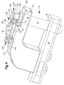
- FIG. 4 shows a perspective view of a first embodiment of a tension element according to the invention.
- the tension member shown in Fig. 4 is an alternative embodiment to the Glaspendelende shown in Figs. 2 and 3.
- a lower tab 40 with a receiving bore 48 and an upper tab 46 with a receiving bore 50 is provided.
- the receiving bores 48, 50 of the trailer bolt 52 can be inserted so as to fix a (not shown in Fig. 4) towing eye of a trailer to the tension element or to couple.
- a Locking device 100 is provided, which has a bore 60 in which the securing bolt 10 is inserted.
- a means 102 is provided which is arranged relative to the locking device 100 such that a movement of the securing bolt 10 into a released position can be prevented.
- the means 102 comprises a shaft-shaped or peg-shaped component 104, which ultimately represents an extension of the attachment bolt 52 upwards.
- the component 104 is arranged such that it is arranged adjacent to or in spatial proximity to the end-side shank portion 16 of the securing bolt 10.
- the component 104 covers almost completely the cross-sectional area of the bore 60 of the locking device 100 in the sense that in the direction of the longitudinal axis of the locking bolt 10, the cross-sectional area of the component 104 can be projected onto the cross-sectional area of the bore 60 and in this case the overlap exists. Therefore, by the lengthened in the longitudinal direction of the trailer bolt 52 embodiment of the trailer bolt 52, the end-side shank portion 16 of the securing bolt 10 is protected from direct effects of external objects.
- the suspension bolt 52 includes a circular shaped collar 106, the lower side on the upper side of the upper tab 46 comes to rest, if the suspension bolt 52 is inserted into the receiving bores 48, 50.
- the collar 106 has a recess 108, which is formed substantially annular with respect to the longitudinal axis of the trailer bolt 52.
- a shoulder portion 110 is provided, which has a larger outer radius than the component 104. The shoulder part 110 serves above all for the simple handling of the attachment bolt 52, because this can in this way be gripped by an operator in a simple manner, in particular for pulling out the attachment bolt 52.
- a depression or a groove 112 is provided on the longitudinal-side surface.
- the groove 112 of the end-side shank portion 16 of the securing bolt 10 may repeatedly come into contact with the collar 106 of the suspension bolt 52, namely, if a drawbar not shown in the figures due to driving the suspension bolt 52 in its longitudinal direction (and if only over small Paths).
- the collar 106 has a structure which is formed substantially complementary to the groove 112 of the securing bolt 10 and comes directly to the groove 112 for engagement or for engagement.
- the securing bolt 10 has at its end facing away from the suspension bolt 52 a square-shaped end 114 which comes to rest with the surface 116 of the upper lug 46.
- the square-shaped end 114 therefore, the securing bolt 10 is secured against rotation with respect to its longitudinal axis, so that a possible rotation of the trailer bolt 52 about its longitudinal axis in direct contact with the end-side shaft portion 16 of the securing bolt 10 no torque on the safety pin transmits and thus the spring element 14 is not deformed by tilting on the component 56 of the locking device 100.
- a groove 118 is provided, which protects the provided at the end 114 of the spring member 14 from deformation or destruction, namely, if an operator the locking pin 10 at the end 114 with a hammer in the locked position (such in FIG. 4).
- FIG. 5 shows a perspective view of a second embodiment according to the invention of a tension element, which is designed substantially similar to the embodiment of FIG. 4.
- the suspension bolt 52 has a substantially rectangular shaped and projecting in the radial direction (collar-shaped) region 120, which comes with an edge surface on the surface 122 of the member 56 and the upper tab 46 for abutment and therefore against rotation of the upper tab 46 in the receiving bores 48, 50 is received.
- the securing bolt 10 has no groove in FIG. 5 at its end-side shank region 16. However, a groove 112, which is comparable to FIG. 4, could also be provided here. Accordingly, a depression (substantially rectangular) could also be provided on the region 120, so that an unintentional movement of the securing bolt 10 into a released position can also be prevented thereby.
Landscapes
- Engineering & Computer Science (AREA)
- Mechanical Engineering (AREA)
- Transportation (AREA)
- General Engineering & Computer Science (AREA)
- Body Structure For Vehicles (AREA)
- Snaps, Bayonet Connections, Set Pins, And Snap Rings (AREA)
- Connection Of Plates (AREA)
- Orthopedics, Nursing, And Contraception (AREA)
- Surgical Instruments (AREA)
- Gripping On Spindles (AREA)
Abstract
Description
Die Erfindung betrifft ein Zugelement mit einer oberen Lasche, einer unteren Lasche und einer Verriegelungseinrichtung. Zwischen den zwei Laschen ist ein Zwischenraum zur Aufnahme einer Zugöse ausgebildet, wobei an der oberen und unteren Lasche je eine Aufnahmebohrung vorgesehen ist, die der Aufnahme eines Anhängebolzens dient. Die Verriegelungseinrichtung weist ein eine Bohrung enthaltendes Bauteil und einen in der Bohrung axial verschiebbaren Sicherungsbolzen auf. Die Verriegelungseinrichtung ist derart an einer Lasche angeordnet, dass im verriegelten Zustand ein aus der Bohrung ragender Bolzenabschnitt des Sicherungsbolzens in die Bewegungsbahn des Anhängebolzens eingreift und diesen an einer axialen Verschiebung hindert.The invention relates to a tension element with an upper flap, a lower flap and a locking device. Between the two tabs, a gap for receiving a drawbar eye is formed, wherein on the upper and lower tab depending on a receiving bore is provided which serves to receive a trailer bolt. The locking device has a component containing a bore and an axially displaceable in the bore securing bolt. The locking device is arranged on a tab such that in the locked state engages a protruding from the bore bolt portion of the locking bolt in the movement path of the towing bolt and prevents it from axial displacement.
Aus dem Stand der Technik ist beispielsweise ein gattungsgemäßes Zugelement aus der
Die in den Fig. 2 und 3 der
Die der Erfindung zugrunde liegende Aufgabe wird darin gesehen, ein Zugelement der eingangs genannten Art anzugeben, durch welches die vorgenannten Probleme gelöst werden. Insbesondere soll ein Zugelement der eingangs genannten Art angegeben und weitergebildet werden, mit welchem die Wahrscheinlichkeit zum unbeabsichtigten Lösen des Anhängebolzens weiter verringert werden kann.The object underlying the invention is seen to provide a tension element of the type mentioned, by which the aforementioned problems are solved. In particular, a tension element of the aforementioned type is to be specified and further developed, with which the probability of unintentional release of the towing bolt can be further reduced.
Die Aufgabe wird erfindungsgemäß durch die Lehre des Patentanspruchs 1 gelöst. Weitere vorteilhafte Ausgestaltungen und Weiterbildungen der Erfindung gehen aus den Unteransprüchen hervor.The object is achieved by the teaching of claim 1. Further advantageous embodiments and modifications of the invention will become apparent from the dependent claims.
Das erfindungsgemäße Zugelement der eingangs genannten Art ist dadurch gekennzeichnet, dass mindestens ein Mittel vorgesehen und derart relativ zur Verriegelungseinrichtung angeordnet ist, dass damit ein - insbesondere durch äußere Gegenstände verursachtes - Verbringen des Sicherungsbolzens in eine freigegebene Stellung verhinderbar ist.
In erfindungsgemäßer Weise ist zunächst erkannt worden, dass es nicht unbedingt erforderlich ist, die Verriegelungseinrichtung derart zu modifizieren, dass diese einer in axialer Richtung des Sicherungsbolzen wirkenden Kraft, welche den Sicherungsbolzen in eine den Anhängebolzen freigebende Stellung verbringen kann, standhalten kann. Vielmehr ist in erfindungsgemäßer Weise ein Mittel vorgesehen, mit welchem ein Gegenstand erst gar nicht auf den Sicherungsbolzen einwirken kann, da das Mittel den Sicherungsbolzen sozusagen dadurch schützt, dass der Gegenstand nicht auf den Sicherungsbolzen auftreffen bzw. zur Anlage kommen kann. Daher können in ganz besonders vorteilhafter Weise insbesondere die vorteilhaften Eigenschaften der in der
In accordance with the invention, it has first been recognized that it is not absolutely necessary to use the locking device such that it can withstand a force acting in the axial direction of the securing bolt force, which can spend the safety pin in a position releasing the towing bolt position. Rather, a means is provided in accordance with the invention, with which an object can not even act on the safety pin, since the means protects the safety bolt so to speak, that the object does not hit the safety pin or can come to rest. Therefore, in a particularly advantageous manner, in particular the advantageous properties of in the
So könnte in einer bevorzugten Ausführungsform an der Lasche, an welcher die Verriegelungseinrichtung vorgesehen ist, ein Vorsprung derart vorgesehen ist, dass bezogen auf die Längsrichtung des Sicherungsbolzens bzw. auf die Bohrungsachse der Vorsprung zumindest teilweise, vorzugsweise vollständig, die Querschnittsfläche der Bohrung oder das Sicherungsbolzenende überdeckt. Mit anderen Worten ist der Vorsprung derart ausgebildet, dass die lotrechte Projektion des Vorsprungs zumindest teilweise oder vollständig die Querschnittsfläche der Bohrung überdeckt. Die Projektion könnte auch in Richtung der Bohrungsachse erfolgen. Jedenfalls ist der Vorsprung bzw. das Mittel derart ausgebildet, dass beispielsweise ein Zugelement, an welchem keine Zugöse adaptiert ist, bei einer Rückwärtsfahrt des Fahrzeugs mit dem Zugelement mit einem Gegenstand (beispielsweise einem Ast oder Zaunteil) in Kontakt kommen kann, wobei dieser Gegenstand aufgrund des Mittels bzw. des Vorsprungs nicht unmittelbar auf den Sicherungsbolzen einwirken kann. Im Konkreten könnte der Vorsprung durch ein einteilig an der Lasche vorgesehenes Metallteil aufweisen. Weiterhin wäre denkbar, dass der Vorsprung in Form eines an der Lasche befestigbares Bauteil ausgebildet ist. Vorzugsweise ist der Vorsprung an einer bezogen zu dem Anbauort des Anhängebolzens abgewandten bzw. gegenüberliegenden Seite des Bauteils vorgesehen.Thus, in a preferred embodiment, on the tab on which the locking device is provided, a projection is provided such that based on the longitudinal direction of the locking bolt or on the bore axis of the projection at least partially, preferably completely, the cross-sectional area of the bore or the safety pin end covered. In other words, the projection is designed such that the vertical projection of the projection at least partially or completely covers the cross-sectional area of the bore. The projection could also take place in the direction of the bore axis. In any case, the projection or the means is designed such that, for example, a tension element to which no towing eye is adapted can come into contact with an object (for example a branch or fence part) when the vehicle is reversing with the tension element, this object being due to the agent or the projection can not act directly on the safety pin. Concretely, the projection could have a metal part provided integrally on the tab. Furthermore, it would be conceivable that the Projection is formed in the form of a fastened to the tab component. Preferably, the projection is provided on a side facing away from the attachment point of the trailer bolt or opposite side of the component.
In einer ganz besonders bevorzugten Ausführungsform ist der Anhängebolzen derart ausgebildet, dass bezogen auf die Längsrichtung des Sicherungsbolzens ein Teil des Anhängebolzens zumindest teilweise, vorzugsweise vollständig, die Querschnittsfläche der Bohrung oder das Sicherungsbolzenende überdeckt. Demgemäß ist an der Lasche nicht unbedingt ein Vorsprung oder dergleichen vorzusehen. Das Mittel ist vielmehr durch eine entsprechende Ausbildung des Anhängebolzens gebildet, nämlich beispielsweise dadurch, dass der Anhängebolzen in seiner Längsrichtung länger als unbedingt notwendig ausgebildet ist und somit im Wesentlichen eine Funktion übernimmt, welche vergleichbar zu dem an der Lasche vorgesehenen oben erwähnten Vorsprung ist. Im Konkreten könnte der Anhängebolzen sich beispielsweise mit seinem oberen Teil unmittelbar oder mittelbar vor den Sicherungsbolzen erstrecken, vorausgesetzt, dass der Anhängebolzen auch in den hierfür an den Laschen vorgesehenen Aufnahmebohrungen eingeführt ist.In a very particularly preferred embodiment, the attachment bolt is designed such that, based on the longitudinal direction of the securing bolt, a part of the attachment bolt at least partially, preferably completely, covers the cross-sectional area of the bore or the securing bolt end. Accordingly, a tab or the like is not necessarily provided on the tab. Rather, the means is formed by a corresponding design of the towing bolt, namely, for example, in that the trailer bolt is designed to be longer than absolutely necessary in its longitudinal direction and thus essentially performs a function which is comparable to the above-mentioned projection provided on the tab. Specifically, the trailer bolt could, for example, with its upper part directly or indirectly extend in front of the securing bolt, provided that the trailer bolt is also inserted into the provided for this purpose on the tabs receiving bores.
Der Anhängebolzen könnte einen in radialer Richtung abragenden Bereich oder einen Kragen aufweisen, welcher eine im Wesentlichen ringförmig ausgebildete Vertiefung aufweisen kann. Der Sicherungsbolzen könnte an seinem dem Anhängebolzen zugewandten Teil oder Ende eine Vertiefung oder eine Nut aufweisen, welche mit dem Bereich bzw. dem Kragen des Anhängebolzens in Eingriff kommt. Hierdurch kann eine schrittweise Bewegung des Sicherungsbolzens in eine freigegebene Stellung auf Grund des Slip-Stick-Effekts vermieden werden, welcher durch Fahrzeugbewegungen und/oder Vibrationen hervorgerufene einzelne Kontakte zwischen Anhängebolzen und Sicherungsbolzen auftretenden kann. Falls nämlich der Anhängebolzen mit dem Sicherungsbolzen in Kontakt kommt, kommt die Vertiefung bzw. Nut an dem Sicherungsbolzen in die Vertiefung an dem radial abragenden Bereich bzw. Kragen zum gegenseitigen Eingriff, so dass die Bewegungsfreiheit des Sicherungsbolzens in seiner Bohrung auf Grund der Anordnung der Vertiefung und der Nut begrenzt ist. Hierdurch kann in ganz besonders vorteilhafter Weise die Wahrscheinlichkeit eines unbeabsichtigten Lösens einer Zugelement-Zugösen-Verbindung verringert werden.The attachment bolt could have a region projecting in the radial direction or a collar, which may have a substantially annular depression. The securing bolt could have at its part or end facing the towing bolt a recess or a groove, which engages with the region or the collar of the towing bolt. In this way, a stepwise movement of the securing bolt can be avoided in a released position due to the slip-stick effect, which can occur caused by vehicle motion and / or vibration individual contacts between the tow bolt and safety bolts. Namely, if the trailer bolt comes into contact with the safety pin, the recess or groove comes on the safety pin in the recess on the radially projecting portion or collar for mutual engagement, so that the freedom of movement of the securing bolt is limited in its bore due to the arrangement of the recess and the groove. This can be reduced in a particularly advantageous manner, the probability of unintentional release of a tension-Zugösen-connection.
Der Sicherungsbolzen könnte an seinem dem Anhängebolzen abgewandten Ende im Wesentlichen vierkantförmig ausgebildet sein. Eine Seite dieses vierkantförmig ausgebildeten Endes kommt hierbei an einem Bauteil oder an der Lasche zur Anlage, so dass ein Verdrehen des Sicherungsbolzens um seine Längsachse auf Grund der vierkantförmigen Ausgestaltung dieses Endes vermieden wird. Hierdurch kann auch eine Belastung des Federelements durch ein auf das Federelement übertragenes Drehmoment weitgehend vermieden werden. Eine Drehung des Sicherungsbolzens um seine Längsachse könnte dann auftreten, wenn der in den Aufnahmebohrungen befindliche Anhängebolzen selbst nicht gegen Verdrehung gesichert ist und bei einem eventuellen Verdrehen (beispielsweise bei einer Kurvenfahrt des Gespanns) mit dem Sicherungsbolzen in Kontakt kommt.The securing bolt could be formed at its end facing away from the trailer bolt substantially square. One side of this square-shaped end comes here on a component or on the tab to the plant, so that a rotation of the locking bolt is avoided around its longitudinal axis due to the square-shaped configuration of this end. In this way, a load of the spring element can be largely avoided by a torque transmitted to the spring element. A rotation of the securing bolt about its longitudinal axis could occur if the suspension bolt located in the receiving bores is not secured against rotation itself and comes in contact with the safety pin in case of a possible twisting (for example, when cornering the trailer).
In einer ganz besonders bevorzugten Ausführungsform ist der Sicherungsbolzen nach einem der Ansprüche 1 bis 3 der
Ebenfalls ganz besonders bevorzugt ist die Verriegelungseinrichtung nach einem der Ansprüche 4 bis 9 der
Anhand der Zeichnung, die ein Ausführungsbeispiel der Erfindung zeigt, werden nachfolgend die Erfindung sowie weitere Vorteile und vorteilhafte Weiterbildungen und Ausgestaltungen der Erfindung näher beschrieben und erläutert.Reference to the drawing, which shows an embodiment of the invention, the invention and further advantages and advantageous developments and refinements of the invention are described and explained in more detail below.
Es zeigt:
- Fig. 1
- einen aus dem Stand der Technik bekannter Sicherungsbolzen mit einem Bolzenelement und einem Federelement,
- Fig. 2
- ein aus dem Stand der Technik bekanntes Zugpendelende mit einer Verrieglungseinrichtung für den Anhängebolzen im nicht verriegelten Zustand,
- Fig. 3
- ein aus dem Stand der Technik bekanntes Zugpendelende mit einer Verrieglungseinrichtung für den Anhängebolzen im verriegelten Zustand,
- Fig. 4
- eine perspektivische Ansicht von der Seite und teilweise von oben eines ersten erfindungsgemäßen Ausführungsbeispiels eines Zugelements und
- Fig. 5
- eine perspektivische Ansicht von oben und teilweise von der Seite eines zweiten erfindungsgemäßen Ausführungsbeispiels eines Zugelements.
- Fig. 1
- a safety pin known from the prior art with a bolt element and a spring element,
- Fig. 2
- a Zugpendelende known from the prior art with a locking device for the towing bolt in the unlocked state,
- Fig. 3
- a Zugpendelende known from the prior art with a locking device for the towing bolt in the locked state,
- Fig. 4
- a perspective view from the side and partly from above of a first embodiment according to the invention of a tension member and
- Fig. 5
- a perspective view from above and partly from the side of a second embodiment of a tension element according to the invention.
Aus Fig. 1 geht ein Sicherungsbolzen 10 hervor, der aus einem Bolzenelement 12 und einem Federelement 14 besteht. Das Bolzenelement 12 ist ein zylindrischer Vollkörper, der einen in eine Bohrung (60, Fig. 2 und 3) einsteckbaren Schaftabschnitt 16 enthält, dessen Ende eine Fase 18 aufweist, die das Einstecken in die Bohrung 60 erleichtert. Im Bereich des dem Schaftabschnitt 16 entgegengesetzten Endes 20 ist in das Bolzenelement 12 eine Querbohrung 22 eingebracht. Des Weiteren befindet sich an diesem Ende 20 eine axial ausgerichtete Stirnbohrung 24, die als Sackbohrung ausgebildet ist.From Fig. 1 shows a securing
Das Federelement 14 besteht aus einem Federstahldraht mit Kreisquerschnitt, der im Wesentlichen G-förmig ausgebildet ist. Der Bauch des G bildet eine Schlaufe 26, die gemeinsam mit zwei im Wesentlichen parallelen zueinander verlaufenden Schenkeln 28, 30 U-förmig gebogen ist. Der mittlere horizontal ausgerichtete erste Endschenkel 32 des G wird gebildet, indem der erste Schenkel 30 um ca. 90° nach innen abgebogen ist. Dieser erste Endschenkel 32 greift in die Querbohrung 22 des Bolzenelements 12 ein. Der obere vertikal ausgerichtete zweite Endschenkel 34 des G wird gebildet, indem der zweite Schenkel 28 zweifach um ca. 90° nach innen abgebogen ist. Dieser zweite Endschenkel 34 greift in die Stirnbohrung 24 des Bolzenelements 12 ein. Das Federelement 14 ist derart vorgespannt, dass seine Schlaufe 26 gegen den Schaftabschnitt 16 des Bolzenelements 12 gedrückt wird und sich an diesem abstützt. Indem die Bedienungsperson mit der Hand einen Druck auf die Schlaufe 26 ausübt, lässt sich diese etwas von dem Schaftabschnitt 16 abheben.The
Die Fig. 2 und 3 zeigen den Endbereich eines Zugelements, welches in diesen Ausführungsbeispielen in Form eines Zugpendels ausgebildet ist, dessen nicht sichtbares anderes (linkes) Ende an einem Fahrzeugrumpf schwenkbar befestigt ist. Auf dem eigentlichen Zugpendel 40 ist ein Oberteil 42 aufgeschraubt, wobei lediglich die der Verschraubung dienenden Bohrungen 44 gezeigt sind. Das Oberteil 42 weist eine in Seitenansicht S-förmige Form auf, so dass der nicht am Zugpendel 40 festgeschraubte Schenkel 46 zum Zugpendel 40 beabstandet ist und ein Zwischenraum 47 zwischen dem Zugpendel 40 und dem Oberteil 42 ausgebildet ist. Im Bereich der freien (rechten) Enden des Zugpendels 40 und des Oberteils 42 befindet sich je eine senkrecht ausgerichtete als Durchgangsbohrung ausgebildete Aufnahmebohrung 48, 50. Die beiden Aufnahmebohrungen 48, 50 fluchten miteinander und nehmen einen Anhängebolzen 52 auf. Der Anhängebolzen 52 hat an seinem oberen Ende einen flachen Kopf 54, der radial über den zylindrischen Schaft des Anhängebolzens 52 übersteht und im Wesentlichen quadratisch ausgebildet ist, wobei die Ecken des Quadrates abgerundet sind. Der Anhängebolzen 52 dient der Befestigung einer nicht dargestellten Öse, die sich beispielsweise an der Deichsel eines anhängbaren Anhängegerätes befindet.Figures 2 and 3 show the end portion of a tension member formed in these embodiments in the form of a drawbar whose non-visible other (left) end is pivotally attached to a vehicle body. On the
Auf der Oberseite des Oberteils 42 ist ein Bauteil 56 einer Verriegelungsvorrichtung 58 befestigt. Die Befestigung kann beispielsweise durch Verschrauben oder Verschweißen erfolgen. Es ist jedoch auch möglich das Oberteil 42 und das Bauteil 56 aus einem Stück zu fertigen. Das Bauteil 56 ist im Wesentlichen quaderförmig ausgebildet und enthält eine Bohrung 60, die im Wesentlichen parallel zur Zugpendelausrichtung verläuft. In die Bohrung 60 ist von der dem Anhängebolzen 52 gegenüberliegenden Seite (links) aus, das Bolzenelement 12 des in Fig. 1 näher dargestellten Sicherungsbolzens 10 derart eingesteckt, dass das mit der Fase 18 versehene Schaftende des Bolzenelements 12 dem Anhängebolzen 52 zugewandt ist.On the upper side of the
An seinem dem Anhängebolzen 52 zugewandten Ende weist das Bauteil 56 eine im Wesentlichen senkrecht ausgerichtete Frontseite 62 auf, aus der die Bohrung 60 austritt. Der obere Bereich des Bauteils 56 ist stufenförmig ausgebildet, wobei sich eine zur Frontseite 62 parallele und in die gleiche Richtung weisende Stirnseite 64 ergibt. Die Oberseite des Bauteils 56 weist eine schräge Rampe 66 auf, deren Abstand zur Achse der Bohrung 60 ausgehend von der Einsteckseite des Bolzenelements 12 bis zur Stirnfläche stetig ansteigt.At its end facing the
Zur Befestigung der Anhängeöse einer Deichsel an dem Zugpendel 10 wird folgendermaßen verfahren:To attach the hitch of a drawbar to the
Zunächst wird das mit der Fase 18 versehene Schaftende des Bolzenelements 12 (von links) in die Bohrung 60 des Bauteils 56 eingeführt. Dann wird die Schlaufe 26 des Federelements 14 von der Bedienungsperson angehoben und auf die Rampe 66 des Bauteils 56 aufgelegt. Sodann wird das Bolzenelement 12 weiter in die Bohrung 60 eingeschoben. Dabei gleitet die Schlaufe 26 des Federelements 14 auf der Rampe 66 bis die Schlaufe 26 die Stirnseite 64 erreicht und in Richtung Bolzenelement 12 schnappt, wie in Fig. 2 dargestellt. Jetzt lässt sich das Bolzenelement 12 nicht mehr zurückziehen, ohne dass die Schlaufe 26 angehoben wird, was wegen der Höhe der Rampe 66 einen nicht unerheblichen Kraftaufwand erfordert. Damit ist der Sicherungsbolzen 10 unverlierbar am Bauteil 56 festgelegt.First, the provided with the
Zum Einfädeln einer nicht dargestellten Anhängeöse wird der Anhängebolzen 52 angehoben und aus der Aufnahmebohrung 48 gezogen, so dass die Anhängeöse in den Zwischenraum 47 eingeführt werden kann. Dabei befindet sich der Sicherungsbolzen 10 in seiner in Fig. 2 dargestellten entriegelten Position, in der das freie Ende des Schaftabschnitts 16 nicht aus dem Bauteil 56 herausragt und keinen Einfluss auf den Anhängebolzen 52 hat. Wenn die Ausnehmung der Anhängeöse mit den Aufnahmebohrungen 48, 50 fluchtet wird der Anhängebolzen 52 nach unten bewegt und durch die Anhängeöse in die Aufnahmebohrung 48 eingesteckt. Der Kopf 54 des Anhängebolzens 52 liegt dann auf der Oberseite des Schenkels 46 des Oberteils 42 auf. Damit sich die Anhängeöse nicht ungewollt vom Zugpendel lösen kann, wird der Anhängebolzen 52 in dieser Lage verriegelt. Zu diesem Zweck braucht der Sicherungsbolzen 10 lediglich in Richtung des Anhängebolzens 52 verschoben zu werden, bis die Schlaufe 26 des Federelements 14 wie in Fig. 3 dargestellt hinter die Frontseite 62 des Bauteils 56 schnappt. Das freie Ende des Schaftabschnitts 16 gleitet dabei über die obere Fläche des Kopfes 54 des Anhängebolzens 52 und verriegelt den Anhängebolzen 52 in dieser Position.For threading a non-illustrated Anhängeöse the
Wegen der Vorspannung des Federelementes 14 verharrt dieses in seiner in Fig. 3 gezeigten Lage. Um den Anhängebolzen 52 zu entriegeln, muss die Bedienungsperson mit einer gewissen Kraftanstrengung gegen die Federkraft die Schlaufe 26 des Federelementes 14 anheben und auf die zwischen der Frontseite 62 und der Stirnseite 64 ausgebildete Fläche 68 des Bauteils 56 auflegen. Nun lässt sich der Sicherungsbolzen 10 zurückziehen, bis die Schlaufe 26 des Federelements 14 die Stirnseite 64 erreicht und das freie Ende des Schaftabschnitts 16 in die Bohrung 60 eingezogen ist und nicht mehr in die Bewegungsbahn des Kopfes 54 des Anhängebolzens 52 eingreift. Der Anhängebolzen 52 lässt sich jetzt nach oben herausziehen, wodurch die Anhängeöse freigegeben wird.Because of the bias of the
Fig. 4 zeigt in einer perspektivischen Ansicht ein erstes erfindungsgemäßes Ausführungsbeispiel eines Zugelements. Das in Fig. 4 gezeigte Zugelement ist eine alternative Ausführung zu dem in den Fig. 2 und 3 gezeigten Zugpendelende. Auch bei dem Zugelement aus Fig. 4 ist eine untere Lasche 40 mit einer Aufnahmebohrung 48 und eine obere Lasche 46 mit einer Aufnahmebohrung 50 vorgesehen. In die Aufnahmebohrungen 48, 50 kann der Anhängebolzen 52 eingeführt werden, um damit eine (in Fig. 4 nicht gezeigte) Zugöse eines Anhängers an dem Zugelement zu fixieren bzw. zu koppeln. An der oberen Lasche 46 ist eine Verriegelungseinrichtung 100 vorgesehen, welche eine Bohrung 60 aufweist, in der der Sicherungsbolzen 10 eingeführt ist.4 shows a perspective view of a first embodiment of a tension element according to the invention. The tension member shown in Fig. 4 is an alternative embodiment to the Zugpendelende shown in Figs. 2 and 3. 4, a
Erfindungsgemäß ist ein Mittel 102 vorgesehen, welches derart relativ zur Verriegelungseinrichtung 100 angeordnet ist, dass damit ein Verbringen des Sicherungsbolzens 10 in eine freigegebene Stellung verhinderbar ist. Im Konkreten umfasst das Mittel 102 ein schaftförmiges oder zapfenförmiges Bauteil 104, welches letztendlich eine Verlängerung des Anhängebolzens 52 nach oben darstellt. Das Bauteil 104 ist derart angeordnet, dass es benachbart zu bzw. in räumlicher Nähe zu dem endseitigen Schaftabschnitt 16 des Sicherungsbolzens 10 angeordnet ist. Somit verdeckt das Bauteil 104 nahezu vollständig die Querschnittsfläche der Bohrung 60 der Verriegelungseinrichtung 100 und zwar in dem Sinn, dass in Richtung der Längsachse des Sicherungsbolzens 10 die Querschnittsfläche des Bauteils 104 auf die Querschnittsfläche der Bohrung 60 projizierbar ist und hierbei die Überdeckung vorliegt. Daher wird durch die in Längsrichtung des Anhängebolzens 52 verlängerte Ausgestaltung des Anhängebolzens 52 der endseitige Schaftbereich 16 des Sicherungsbolzens 10 von unmittelbaren Einwirkungen externer Gegenstände geschützt.According to the invention, a
Der Anhängebolzen 52 umfasst einen kreisförmig ausgebildeten Kragen 106, dessen untere Seite auf der obere Seite der oberen Lasche 46 zur Anlage kommt, falls der Anhängebolzen 52 in den Aufnahmebohrungen 48, 50 eingeführt ist. Der Kragen 106 weist eine Vertiefung 108 auf, welche im Wesentlichen ringförmig bezüglich der Längsachse des Anhängebolzens 52 ausgebildet ist. An dem oberen Ende des Anhängebolzens 52 ist ein Schulterteil 110 vorgesehen, welches einen größeren Außenradius als das Bauteil 104 aufweist. Das Schulterteil 110 dient vor allem zur einfachen Handhabung des Anhängebolzens 52, dieser kann nämlich hierdurch in einfacher Weise von einem Bediener gegriffen werden, insbesondere zum Herausziehen des Anhängebolzens 52.The
An dem endseitigen Schaftbereich 16 des Sicherungsbolzens 10 ist an der längsseitigen Oberfläche eine Vertiefung bzw. eine Nut 112 vorgesehen. Die Nut 112 des endseitigen Schaftbereichs 16 des Sicherungsbolzens 10 kommt unter Umständen mit dem Kragen 106 des Anhängebolzens 52 wiederholt in Kontakt, falls nämlich eine in den Figuren nicht gezeigte Zugöse auf Grund von Fahrbewegungen den Anhängebolzen 52 in seiner Längsrichtung (und wenn auch nur über kleine Wege) bewegt. Durch die vorgesehene Vertiefung 108 weist der Kragen 106 eine Struktur auf, welche im Wesentlichen komplementär zur Nut 112 des Sicherungsbolzens 10 ausgebildet ist und unmittelbar mit der Nut 112 zur Anlage bzw. zum Eingriff kommt. Auf Grund dieser Ausbildung des endseitigen Bereichs des Sicherungsbolzens 10 in Zusammenwirkung mit dem Kragen 106 kann eine schrittweise Bewegung des Sicherungsbolzens 10 in eine freigegebene Stellung (eine Bewegung nach links innerhalb der Bohrung 16 aus Fig. 4) verhindert werden, so dass der Anhängebolzen 52 während des Betriebs eben nicht unbeabsichtigt sich durch Slip-Stick-Effekt nach oben in eine freigegebene Stellung bewegt werden kann.At the end-
Der Sicherungsbolzen 10 weist an seinem dem Anhängebolzen 52 abgewandten Ende ein vierkantförmiges Ende 114 auf, welches mit der Oberfläche 116 der oberen Lasche 46 zur Anlage kommt. Durch das vierkantförmige Ende 114 ist daher der Sicherungsbolzen 10 vor einer Verdrehung bezüglich seiner Längsachse gesichert, so dass eine eventuelle Drehung des Anhängebolzens 52 um seine Längsachse bei unmittelbarem Kontakt mit dem endseitigen Schaftbereich 16 des Sicherungsbolzens 10 kein Drehmoment auf den Sicherungsbolzen überträgt und somit das Federelement 14 nicht durch Verkanten an dem Bauteil 56 der Verriegelungseinrichtung 100 verformt wird. An der Stirnseite des vierkantförmigen Endes 114 ist eine Rille 118 vorgesehen, welche den an dem Ende 114 vorgesehenen Teil des Federelements 14 vor Verformung oder Zerstörung schützt, falls nämlich ein Bediener den Sicherungsbolzen 10 an dem Ende 114 mit einem Hammer in die verriegelte Stellung (wie in Fig. 4 gezeigt) verbringen möchte.The securing
Fig. 5 zeigt in einer perspektivischen Ansicht ein zweites erfindungsgemäßes Ausführungsbeispiel eines Zugelements, welches im Wesentlichen ähnlich zu dem Ausführungsbeispiel aus Fig. 4 ausgeführt ist. Der Anhängebolzen 52 weist einen im Wesentlichen rechteckförmige ausgebildeten und in radialer Richtung abragenden (kragenförmigen) Bereich 120 auf, welcher mit einer Kantenfläche an der Oberfläche 122 des Bauteils 56 bzw. der oberen Lasche 46 zur Anlage kommt und daher verdrehsicher gegenüber der oberen Lasche 46 in den Aufnahmebohrungen 48, 50 aufgenommen ist. Der Sicherungsbolzen 10 weist in Fig. 5 an seinem endseitigen Schaftbereich 16 keine Nut auf. Eine vergleichbar zu Fig. 4 vorgesehenen Nut 112 könnte allerdings auch hier vorgesehen sein. Dementsprechend könnte auch an dem Bereich 120 eine Vertiefung (im Wesentlichen rechteckförmig ausgebildet) vorgesehen sein, so dass auch hierdurch ein unbeabsichtigtes Verbringen des Sicherungsbolzens 10 in eine freigegebene Stellung verhinderbar ist.5 shows a perspective view of a second embodiment according to the invention of a tension element, which is designed substantially similar to the embodiment of FIG. 4. The
Auch wenn die Erfindung lediglich anhand eines Ausführungsbeispiels beschrieben wurde, erschließen sich für den Fachmann im Lichte der vorstehenden Beschreibung sowie der Zeichnung viele verschiedenartige Alternativen, Modifikationen und Varianten, die unter die vorliegende Erfindung fallen.Although the invention has been described by way of example only, in light of the foregoing description and the drawings, those skilled in the art will recognize many different alternatives, modifications and variations which are within the scope of the present invention.
Claims (8)
Applications Claiming Priority (1)
| Application Number | Priority Date | Filing Date | Title |
|---|---|---|---|
| DE102005058811A DE102005058811A1 (en) | 2005-12-09 | 2005-12-09 | tension element |
Publications (2)
| Publication Number | Publication Date |
|---|---|
| EP1795383A1 true EP1795383A1 (en) | 2007-06-13 |
| EP1795383B1 EP1795383B1 (en) | 2009-08-19 |
Family
ID=37622049
Family Applications (1)
| Application Number | Title | Priority Date | Filing Date |
|---|---|---|---|
| EP06125374A Active EP1795383B1 (en) | 2005-12-09 | 2006-12-05 | Tension member |
Country Status (5)
| Country | Link |
|---|---|
| US (1) | US7530592B2 (en) |
| EP (1) | EP1795383B1 (en) |
| AT (1) | ATE439990T1 (en) |
| BR (1) | BRPI0605195B1 (en) |
| DE (2) | DE102005058811A1 (en) |
Cited By (1)
| Publication number | Priority date | Publication date | Assignee | Title |
|---|---|---|---|---|
| AT513877A1 (en) * | 2013-01-17 | 2014-08-15 | Scharmüller Josef Ing | drawbar |
Families Citing this family (10)
| Publication number | Priority date | Publication date | Assignee | Title |
|---|---|---|---|---|
| US7416206B2 (en) * | 2006-06-05 | 2008-08-26 | Deere & Company | Drawbar hammer strap pin lock |
| GB0621619D0 (en) * | 2006-10-31 | 2006-12-06 | Agco Sa | Draw pin hitches |
| US7625003B2 (en) * | 2007-09-04 | 2009-12-01 | Cnh America Llc | Tractor drawbar assembly |
| CA2607412A1 (en) * | 2007-10-23 | 2009-04-23 | Powerpin Inc. | Hitch for multiple drawpin sizes |
| US8210559B2 (en) * | 2010-01-15 | 2012-07-03 | Gregory Alan Russell | Trailer hitch device |
| US8632091B2 (en) * | 2011-12-20 | 2014-01-21 | Agco Corporation | Drawbar pin retention device |
| US9579940B2 (en) * | 2013-02-22 | 2017-02-28 | Progress Mfg. Inc. | Rotating retainer clip for weight distribution hitch spring arm retaining pin |
| US9809069B2 (en) * | 2015-11-04 | 2017-11-07 | Agco Corporation | Drawbar pin ejector |
| US10179488B2 (en) * | 2015-11-04 | 2019-01-15 | Agco Corporation | Drawbar assembly with pin ejector mechanism |
| US11964522B2 (en) | 2021-03-15 | 2024-04-23 | Deere & Company | Implement attachment assembly and method of use |
Citations (6)
| Publication number | Priority date | Publication date | Assignee | Title |
|---|---|---|---|---|
| US2509459A (en) * | 1945-11-01 | 1950-05-30 | Brown Fayro Company | Car coupler hitching-pin retaining means |
| DE1145494B (en) * | 1958-09-27 | 1963-03-14 | Jost Werke | Trailer coupling for motor vehicles |
| DE1630585A1 (en) * | 1967-04-22 | 1971-06-09 | Kloeckner Humboldt Deutz Ag | Fuse for the coupling pin of a trailer coupling |
| US3685864A (en) * | 1971-03-22 | 1972-08-22 | Robert M Hall | Locking pin coupling |
| FR2200797A5 (en) * | 1972-09-28 | 1974-04-19 | Douaisis Atel M Caniques | |
| DE10322933A1 (en) | 2003-05-21 | 2004-12-16 | Deere & Company, Moline | Safety bolt, locking device and tension element |
Family Cites Families (11)
| Publication number | Priority date | Publication date | Assignee | Title |
|---|---|---|---|---|
| US1248586A (en) * | 1917-01-29 | 1917-12-04 | Wood Equipment Company | Car-coupling. |
| US2441285A (en) * | 1945-12-13 | 1948-05-11 | John W Pfeiffer | Automatic hitch |
| US2593247A (en) * | 1950-10-10 | 1952-04-15 | Arland E Benteman | Coupling pin lock for trailer hitches |
| US2654613A (en) * | 1952-03-28 | 1953-10-06 | Deere Mfg Co | Implement and trailer hitch |
| US4006917A (en) * | 1975-07-14 | 1977-02-08 | Caterpillar Tractor Co. | Energy absorbing pull hook for construction vehicles |
| US4579364A (en) * | 1984-08-06 | 1986-04-01 | Kranz Roy F | Releasable lock mechanism for hitch pins |
| US5193835A (en) * | 1990-05-21 | 1993-03-16 | Sheets Orville G | Boat retainer |
| DE4041838A1 (en) * | 1990-12-24 | 1992-06-25 | Kloeckner Humboldt Deutz Ag | Detachable bolt esp. for use between vehicle and trailer - has head with radial hole in and shank with clamping sleeve |
| US20010054807A1 (en) * | 1999-09-02 | 2001-12-27 | Homan Todd B. | Hitch pin retainer Assembly |
| US6758486B1 (en) * | 2002-12-20 | 2004-07-06 | Deere & Company | Drawbar clevis assembly |
| US7478824B2 (en) * | 2006-09-20 | 2009-01-20 | Deere & Company | Drawbar hammer strap assembly with pin trigger |
-
2005
- 2005-12-09 DE DE102005058811A patent/DE102005058811A1/en not_active Withdrawn
-
2006
- 2006-12-05 DE DE502006004576T patent/DE502006004576D1/en active Active
- 2006-12-05 EP EP06125374A patent/EP1795383B1/en active Active
- 2006-12-05 AT AT06125374T patent/ATE439990T1/en not_active IP Right Cessation
- 2006-12-07 BR BRPI0605195-2A patent/BRPI0605195B1/en active IP Right Grant
-
2007
- 2007-01-10 US US11/651,639 patent/US7530592B2/en active Active
Patent Citations (6)
| Publication number | Priority date | Publication date | Assignee | Title |
|---|---|---|---|---|
| US2509459A (en) * | 1945-11-01 | 1950-05-30 | Brown Fayro Company | Car coupler hitching-pin retaining means |
| DE1145494B (en) * | 1958-09-27 | 1963-03-14 | Jost Werke | Trailer coupling for motor vehicles |
| DE1630585A1 (en) * | 1967-04-22 | 1971-06-09 | Kloeckner Humboldt Deutz Ag | Fuse for the coupling pin of a trailer coupling |
| US3685864A (en) * | 1971-03-22 | 1972-08-22 | Robert M Hall | Locking pin coupling |
| FR2200797A5 (en) * | 1972-09-28 | 1974-04-19 | Douaisis Atel M Caniques | |
| DE10322933A1 (en) | 2003-05-21 | 2004-12-16 | Deere & Company, Moline | Safety bolt, locking device and tension element |
Cited By (3)
| Publication number | Priority date | Publication date | Assignee | Title |
|---|---|---|---|---|
| AT513877A1 (en) * | 2013-01-17 | 2014-08-15 | Scharmüller Josef Ing | drawbar |
| AT513877B1 (en) * | 2013-01-17 | 2014-11-15 | Scharmüller Josef Ing | drawbar |
| US9522581B2 (en) | 2013-01-17 | 2016-12-20 | Josef Scharmüller | Drawbar |
Also Published As
| Publication number | Publication date |
|---|---|
| US20070145719A1 (en) | 2007-06-28 |
| DE102005058811A1 (en) | 2007-06-14 |
| DE502006004576D1 (en) | 2009-10-01 |
| EP1795383B1 (en) | 2009-08-19 |
| BRPI0605195B1 (en) | 2019-07-30 |
| ATE439990T1 (en) | 2009-09-15 |
| BRPI0605195A (en) | 2007-10-09 |
| US7530592B2 (en) | 2009-05-12 |
Similar Documents
| Publication | Publication Date | Title |
|---|---|---|
| EP1795383B1 (en) | Tension member | |
| EP2490974B1 (en) | Means of attachment and load lifting system for use with such a means of attachment | |
| DE4107603C1 (en) | ||
| DE4310027C1 (en) | Side strut for a lower link of a tractor | |
| EP3529503B1 (en) | Fixing element for securing a retaining element on a support and system comprising a fixing element and a retaining element | |
| EP0654611A1 (en) | Ringscrew | |
| EP1825060A1 (en) | Non-positive fit elastic rail connection for track systems | |
| EP1738084A1 (en) | Lifting bolt comprising safety element | |
| EP1752668A2 (en) | Arrangement for preventing axial movement of a bolt provided with a groove | |
| DE3104156A1 (en) | CONNECTOR FOR ATTACHING A WIPER BLADE TO A WIPER LEVER | |
| DE102012218762A1 (en) | DEVICE FOR SECURING LOADEGUT | |
| EP1829716B1 (en) | Tow bar for motor vehicles | |
| EP0281836B1 (en) | Belt-connecting device | |
| DE19934238C1 (en) | Device for actuating a clutch, in particular for motor vehicles | |
| EP1479925B1 (en) | Locking bolt, locking device and towing element | |
| WO2002064985A1 (en) | Fixing device for securing an actuating cable | |
| EP2489592B1 (en) | Towbar | |
| EP0958949B1 (en) | Lateral connector for antiskid chain | |
| EP0529427A1 (en) | Hitch coupling device with swinging draw bar | |
| EP3117734B1 (en) | Belt tensioner | |
| DE102004028585B4 (en) | Fastener for attaching a container to a vehicle | |
| EP1477365B1 (en) | Fastening device for roof box | |
| EP4012200B1 (en) | Spring-loaded detent bolt | |
| EP1302341B1 (en) | Trailer coupling | |
| DE10262182B4 (en) | Locking device of a longitudinal adjusting unit of a vehicle seat has a plunger pin with a groove region located close to a lower end of an opening when the plunger pin is locked in the one of the locking openings |
Legal Events
| Date | Code | Title | Description |
|---|---|---|---|
| PUAI | Public reference made under article 153(3) epc to a published international application that has entered the european phase |
Free format text: ORIGINAL CODE: 0009012 |
|
| AK | Designated contracting states |
Kind code of ref document: A1 Designated state(s): AT BE BG CH CY CZ DE DK EE ES FI FR GB GR HU IE IS IT LI LT LU LV MC NL PL PT RO SE SI SK TR |
|
| AX | Request for extension of the european patent |
Extension state: AL BA HR MK YU |
|
| 17P | Request for examination filed |
Effective date: 20071213 |
|
| AKX | Designation fees paid |
Designated state(s): AT BE BG CH CY CZ DE DK EE ES FI FR GB GR HU IE IS IT LI LT LU LV MC NL PL PT RO SE SI SK TR |
|
| 17Q | First examination report despatched |
Effective date: 20080118 |
|
| GRAP | Despatch of communication of intention to grant a patent |
Free format text: ORIGINAL CODE: EPIDOSNIGR1 |
|
| GRAS | Grant fee paid |
Free format text: ORIGINAL CODE: EPIDOSNIGR3 |
|
| GRAA | (expected) grant |
Free format text: ORIGINAL CODE: 0009210 |
|
| AK | Designated contracting states |
Kind code of ref document: B1 Designated state(s): AT BE BG CH CY CZ DE DK EE ES FI FR GB GR HU IE IS IT LI LT LU LV MC NL PL PT RO SE SI SK TR |
|
| REG | Reference to a national code |
Ref country code: GB Ref legal event code: FG4D Free format text: NOT ENGLISH |
|
| REG | Reference to a national code |
Ref country code: CH Ref legal event code: EP |
|
| REG | Reference to a national code |
Ref country code: IE Ref legal event code: FG4D |
|
| REF | Corresponds to: |
Ref document number: 502006004576 Country of ref document: DE Date of ref document: 20091001 Kind code of ref document: P |
|
| LTIE | Lt: invalidation of european patent or patent extension |
Effective date: 20090819 |
|
| PG25 | Lapsed in a contracting state [announced via postgrant information from national office to epo] |
Ref country code: IS Free format text: LAPSE BECAUSE OF FAILURE TO SUBMIT A TRANSLATION OF THE DESCRIPTION OR TO PAY THE FEE WITHIN THE PRESCRIBED TIME-LIMIT Effective date: 20091219 Ref country code: FI Free format text: LAPSE BECAUSE OF FAILURE TO SUBMIT A TRANSLATION OF THE DESCRIPTION OR TO PAY THE FEE WITHIN THE PRESCRIBED TIME-LIMIT Effective date: 20090819 Ref country code: ES Free format text: LAPSE BECAUSE OF FAILURE TO SUBMIT A TRANSLATION OF THE DESCRIPTION OR TO PAY THE FEE WITHIN THE PRESCRIBED TIME-LIMIT Effective date: 20091130 Ref country code: SE Free format text: LAPSE BECAUSE OF FAILURE TO SUBMIT A TRANSLATION OF THE DESCRIPTION OR TO PAY THE FEE WITHIN THE PRESCRIBED TIME-LIMIT Effective date: 20090819 Ref country code: LT Free format text: LAPSE BECAUSE OF FAILURE TO SUBMIT A TRANSLATION OF THE DESCRIPTION OR TO PAY THE FEE WITHIN THE PRESCRIBED TIME-LIMIT Effective date: 20090819 |
|
| NLV1 | Nl: lapsed or annulled due to failure to fulfill the requirements of art. 29p and 29m of the patents act | ||
| PG25 | Lapsed in a contracting state [announced via postgrant information from national office to epo] |
Ref country code: LV Free format text: LAPSE BECAUSE OF FAILURE TO SUBMIT A TRANSLATION OF THE DESCRIPTION OR TO PAY THE FEE WITHIN THE PRESCRIBED TIME-LIMIT Effective date: 20090819 Ref country code: PL Free format text: LAPSE BECAUSE OF FAILURE TO SUBMIT A TRANSLATION OF THE DESCRIPTION OR TO PAY THE FEE WITHIN THE PRESCRIBED TIME-LIMIT Effective date: 20090819 Ref country code: SI Free format text: LAPSE BECAUSE OF FAILURE TO SUBMIT A TRANSLATION OF THE DESCRIPTION OR TO PAY THE FEE WITHIN THE PRESCRIBED TIME-LIMIT Effective date: 20090819 Ref country code: NL Free format text: LAPSE BECAUSE OF FAILURE TO SUBMIT A TRANSLATION OF THE DESCRIPTION OR TO PAY THE FEE WITHIN THE PRESCRIBED TIME-LIMIT Effective date: 20090819 |
|
| REG | Reference to a national code |
Ref country code: IE Ref legal event code: FD4D |
|
| PG25 | Lapsed in a contracting state [announced via postgrant information from national office to epo] |
Ref country code: CY Free format text: LAPSE BECAUSE OF FAILURE TO SUBMIT A TRANSLATION OF THE DESCRIPTION OR TO PAY THE FEE WITHIN THE PRESCRIBED TIME-LIMIT Effective date: 20090819 Ref country code: PT Free format text: LAPSE BECAUSE OF FAILURE TO SUBMIT A TRANSLATION OF THE DESCRIPTION OR TO PAY THE FEE WITHIN THE PRESCRIBED TIME-LIMIT Effective date: 20091221 Ref country code: BG Free format text: LAPSE BECAUSE OF FAILURE TO SUBMIT A TRANSLATION OF THE DESCRIPTION OR TO PAY THE FEE WITHIN THE PRESCRIBED TIME-LIMIT Effective date: 20091119 |
|
| PG25 | Lapsed in a contracting state [announced via postgrant information from national office to epo] |
Ref country code: RO Free format text: LAPSE BECAUSE OF FAILURE TO SUBMIT A TRANSLATION OF THE DESCRIPTION OR TO PAY THE FEE WITHIN THE PRESCRIBED TIME-LIMIT Effective date: 20090819 Ref country code: EE Free format text: LAPSE BECAUSE OF FAILURE TO SUBMIT A TRANSLATION OF THE DESCRIPTION OR TO PAY THE FEE WITHIN THE PRESCRIBED TIME-LIMIT Effective date: 20090819 Ref country code: CZ Free format text: LAPSE BECAUSE OF FAILURE TO SUBMIT A TRANSLATION OF THE DESCRIPTION OR TO PAY THE FEE WITHIN THE PRESCRIBED TIME-LIMIT Effective date: 20090819 Ref country code: IE Free format text: LAPSE BECAUSE OF FAILURE TO SUBMIT A TRANSLATION OF THE DESCRIPTION OR TO PAY THE FEE WITHIN THE PRESCRIBED TIME-LIMIT Effective date: 20090819 Ref country code: DK Free format text: LAPSE BECAUSE OF FAILURE TO SUBMIT A TRANSLATION OF THE DESCRIPTION OR TO PAY THE FEE WITHIN THE PRESCRIBED TIME-LIMIT Effective date: 20090819 |
|
| PG25 | Lapsed in a contracting state [announced via postgrant information from national office to epo] |
Ref country code: SK Free format text: LAPSE BECAUSE OF FAILURE TO SUBMIT A TRANSLATION OF THE DESCRIPTION OR TO PAY THE FEE WITHIN THE PRESCRIBED TIME-LIMIT Effective date: 20090819 |
|
| PLBE | No opposition filed within time limit |
Free format text: ORIGINAL CODE: 0009261 |
|
| STAA | Information on the status of an ep patent application or granted ep patent |
Free format text: STATUS: NO OPPOSITION FILED WITHIN TIME LIMIT |
|
| 26N | No opposition filed |
Effective date: 20100520 |
|
| PG25 | Lapsed in a contracting state [announced via postgrant information from national office to epo] |
Ref country code: MC Free format text: LAPSE BECAUSE OF NON-PAYMENT OF DUE FEES Effective date: 20100701 |
|
| PG25 | Lapsed in a contracting state [announced via postgrant information from national office to epo] |
Ref country code: GR Free format text: LAPSE BECAUSE OF FAILURE TO SUBMIT A TRANSLATION OF THE DESCRIPTION OR TO PAY THE FEE WITHIN THE PRESCRIBED TIME-LIMIT Effective date: 20091120 |
|
| PG25 | Lapsed in a contracting state [announced via postgrant information from national office to epo] |
Ref country code: LU Free format text: LAPSE BECAUSE OF NON-PAYMENT OF DUE FEES Effective date: 20091205 |
|
| PG25 | Lapsed in a contracting state [announced via postgrant information from national office to epo] |
Ref country code: AT Free format text: LAPSE BECAUSE OF NON-PAYMENT OF DUE FEES Effective date: 20091205 |
|
| PG25 | Lapsed in a contracting state [announced via postgrant information from national office to epo] |
Ref country code: HU Free format text: LAPSE BECAUSE OF FAILURE TO SUBMIT A TRANSLATION OF THE DESCRIPTION OR TO PAY THE FEE WITHIN THE PRESCRIBED TIME-LIMIT Effective date: 20100220 |
|
| REG | Reference to a national code |
Ref country code: CH Ref legal event code: PL |
|
| PG25 | Lapsed in a contracting state [announced via postgrant information from national office to epo] |
Ref country code: TR Free format text: LAPSE BECAUSE OF FAILURE TO SUBMIT A TRANSLATION OF THE DESCRIPTION OR TO PAY THE FEE WITHIN THE PRESCRIBED TIME-LIMIT Effective date: 20090819 |
|
| PG25 | Lapsed in a contracting state [announced via postgrant information from national office to epo] |
Ref country code: CH Free format text: LAPSE BECAUSE OF NON-PAYMENT OF DUE FEES Effective date: 20101231 Ref country code: LI Free format text: LAPSE BECAUSE OF NON-PAYMENT OF DUE FEES Effective date: 20101231 |
|
| REG | Reference to a national code |
Ref country code: FR Ref legal event code: PLFP Year of fee payment: 10 |
|
| REG | Reference to a national code |
Ref country code: FR Ref legal event code: PLFP Year of fee payment: 11 |
|
| PG25 | Lapsed in a contracting state [announced via postgrant information from national office to epo] |
Ref country code: IT Free format text: LAPSE BECAUSE OF NON-PAYMENT OF DUE FEES Effective date: 20151205 |
|
| PG25 | Lapsed in a contracting state [announced via postgrant information from national office to epo] |
Ref country code: IT Free format text: LAPSE BECAUSE OF NON-PAYMENT OF DUE FEES Effective date: 20151205 |
|
| PGRI | Patent reinstated in contracting state [announced from national office to epo] |
Ref country code: IT Effective date: 20170710 |
|
| REG | Reference to a national code |
Ref country code: FR Ref legal event code: PLFP Year of fee payment: 12 |
|
| PGFP | Annual fee paid to national office [announced via postgrant information from national office to epo] |
Ref country code: GB Payment date: 20231227 Year of fee payment: 18 |
|
| PGFP | Annual fee paid to national office [announced via postgrant information from national office to epo] |
Ref country code: IT Payment date: 20231220 Year of fee payment: 18 Ref country code: FR Payment date: 20231227 Year of fee payment: 18 Ref country code: DE Payment date: 20231121 Year of fee payment: 18 |
|
| PGFP | Annual fee paid to national office [announced via postgrant information from national office to epo] |
Ref country code: BE Payment date: 20231227 Year of fee payment: 18 |