EP1795289B1 - Cutting method and combination of a band saw blade and a band saw guide unit of a band saw machine - Google Patents
Cutting method and combination of a band saw blade and a band saw guide unit of a band saw machine Download PDFInfo
- Publication number
- EP1795289B1 EP1795289B1 EP05772655.6A EP05772655A EP1795289B1 EP 1795289 B1 EP1795289 B1 EP 1795289B1 EP 05772655 A EP05772655 A EP 05772655A EP 1795289 B1 EP1795289 B1 EP 1795289B1
- Authority
- EP
- European Patent Office
- Prior art keywords
- band saw
- saw blade
- concave
- convex portions
- equal
- Prior art date
- Legal status (The legal status is an assumption and is not a legal conclusion. Google has not performed a legal analysis and makes no representation as to the accuracy of the status listed.)
- Ceased
Links
- 238000000034 method Methods 0.000 title claims description 32
- 238000007654 immersion Methods 0.000 claims description 7
- 241000763859 Dyckia brevifolia Species 0.000 description 261
- 239000011295 pitch Substances 0.000 description 23
- 238000010586 diagram Methods 0.000 description 6
- 238000009751 slip forming Methods 0.000 description 5
- 230000002035 prolonged effect Effects 0.000 description 3
- 238000005452 bending Methods 0.000 description 2
- 238000005096 rolling process Methods 0.000 description 2
- 238000007796 conventional method Methods 0.000 description 1
- 230000001419 dependent effect Effects 0.000 description 1
- 239000002184 metal Substances 0.000 description 1
- 230000036346 tooth eruption Effects 0.000 description 1
- 230000003313 weakening effect Effects 0.000 description 1
- 239000002023 wood Substances 0.000 description 1
Images


Classifications
-
- B—PERFORMING OPERATIONS; TRANSPORTING
- B23—MACHINE TOOLS; METAL-WORKING NOT OTHERWISE PROVIDED FOR
- B23D—PLANING; SLOTTING; SHEARING; BROACHING; SAWING; FILING; SCRAPING; LIKE OPERATIONS FOR WORKING METAL BY REMOVING MATERIAL, NOT OTHERWISE PROVIDED FOR
- B23D55/00—Sawing machines or sawing devices working with strap saw blades, characterised only by constructional features of particular parts
- B23D55/08—Sawing machines or sawing devices working with strap saw blades, characterised only by constructional features of particular parts of devices for guiding or feeding strap saw blades
- B23D55/082—Devices for guiding strap saw blades
-
- B—PERFORMING OPERATIONS; TRANSPORTING
- B23—MACHINE TOOLS; METAL-WORKING NOT OTHERWISE PROVIDED FOR
- B23D—PLANING; SLOTTING; SHEARING; BROACHING; SAWING; FILING; SCRAPING; LIKE OPERATIONS FOR WORKING METAL BY REMOVING MATERIAL, NOT OTHERWISE PROVIDED FOR
- B23D55/00—Sawing machines or sawing devices working with strap saw blades, characterised only by constructional features of particular parts
- B23D55/08—Sawing machines or sawing devices working with strap saw blades, characterised only by constructional features of particular parts of devices for guiding or feeding strap saw blades
- B23D55/088—Devices for feeding strap saw blades
-
- B—PERFORMING OPERATIONS; TRANSPORTING
- B23—MACHINE TOOLS; METAL-WORKING NOT OTHERWISE PROVIDED FOR
- B23D—PLANING; SLOTTING; SHEARING; BROACHING; SAWING; FILING; SCRAPING; LIKE OPERATIONS FOR WORKING METAL BY REMOVING MATERIAL, NOT OTHERWISE PROVIDED FOR
- B23D61/00—Tools for sawing machines or sawing devices; Clamping devices for these tools
- B23D61/12—Straight saw blades; Strap saw blades
- B23D61/123—Details of saw blade body
-
- Y—GENERAL TAGGING OF NEW TECHNOLOGICAL DEVELOPMENTS; GENERAL TAGGING OF CROSS-SECTIONAL TECHNOLOGIES SPANNING OVER SEVERAL SECTIONS OF THE IPC; TECHNICAL SUBJECTS COVERED BY FORMER USPC CROSS-REFERENCE ART COLLECTIONS [XRACs] AND DIGESTS
- Y10—TECHNICAL SUBJECTS COVERED BY FORMER USPC
- Y10T—TECHNICAL SUBJECTS COVERED BY FORMER US CLASSIFICATION
- Y10T83/00—Cutting
- Y10T83/04—Processes
- Y10T83/0405—With preparatory or simultaneous ancillary treatment of work
-
- Y—GENERAL TAGGING OF NEW TECHNOLOGICAL DEVELOPMENTS; GENERAL TAGGING OF CROSS-SECTIONAL TECHNOLOGIES SPANNING OVER SEVERAL SECTIONS OF THE IPC; TECHNICAL SUBJECTS COVERED BY FORMER USPC CROSS-REFERENCE ART COLLECTIONS [XRACs] AND DIGESTS
- Y10—TECHNICAL SUBJECTS COVERED BY FORMER USPC
- Y10T—TECHNICAL SUBJECTS COVERED BY FORMER US CLASSIFICATION
- Y10T83/00—Cutting
- Y10T83/929—Tool or tool with support
- Y10T83/9319—Toothed blade or tooth therefor
- Y10T83/935—Plural tooth groups
Definitions
- the present invention relates to a cutting method for cutting a workpiece in a cutting region and a combination of a band saw blade and a band saw guide unit of a band saw machine.
- a band saw machine is often used when a metal or wood workpiece is to be cut and the band saw machine includes a band saw blade as a cutting tool.
- the band saw blade includes many teeth including many unset teeth, many right set teeth set rightward, and many left set teeth set leftward.
- Japanese Patent Brochure No. 2953767 is known.
- Prior art document EP 0 795 369 A2 discloses a band saw blade which has less difference in cut areas of workpieces with small diameters and cut areas of workpieces with large diameters, and is capable of weakening the cutting resistance and preventing unintentional bending of a cutting line and noise generation when a workpiece, which cannot easily be cut, is cut.
- the band saw blade has, on the back surface of a body thereof, a wavy back surface which is changed periodically or irregularly.
- a plurality of imaginary curves running parallel to the wavy undulation provided for the back surface are formed opposite to the back surface.
- a plurality of saw teeth having tooth tips which substantially describe the imaginary curves are formed.
- Prior art document WO 98/35798 A1 discloses a band saw blade for applications where clogging of the cut by sawdust is a problem, having cutting teeth at a front edge of the blade, and aligned straight portions separated by short shallow notches at a rear edge.
- a cutting length of the band saw blade becomes larger and a cutting resistance of the workpiece becomes higher. Due to this, the band saw blade causes a cutting course deviation, which disadvantageously shortens a service life of the band saw blade, increases the cutting noise, and degrades the work environment.
- It is an object of the present invention is to provide a cutting method and a combination of a band saw blade and a band saw guide unit of a band saw machine capable of suppressing a cutting course deviation of the band saw blade, prolonging a service life of the band saw blade, and reducing cutting noise.
- said object is solved by a cutting method having the features of independent claim 1. Moreover, said object is also solved by a combination of a band saw blade and a band saw guide unit of a band saw machine having the features of independent claim 3. Preferred embodiments are laid down in the dependent claims.
- a first aspect provides a band saw blade supported by a band saw guide unit of a band saw machine so that the band saw blade is able to travel and including a plurality of teeth
- the band saw blade comprising: a plurality of concave portions and a plurality of convex portions which are consecutively formed on a rear of the band saw blade, wherein each of the concave portions is engageable with and disengageable from a backup guide of the band saw guide unit, and each of the convex portions is adjacent to each of the concave portions, and a length of each of the concave portions and each of the convex portions is equal to or smaller than a fourfold of a maximum pitch of a tooth top of each of the teeth.
- a second aspect provides the band saw blade according to the first aspect, wherein the length of each of the concave portions and each of the convex portions is equal to or smaller than a threefold of the maximum pitch of the tooth top of each of the teeth.
- a third aspect provides the band saw blade according to the first aspect or the second aspect, wherein each of the concave portions and each of the convex portions are classified into a plurality of types according to the length of each of the concave portions and each of the convex portions.
- a fourth aspect provides the band saw blade according to any one of the first aspect to the third aspect, wherein the concave portions among the plurality of concave portions and the plurality of convex portions are classified into a plurality of types according to a length of each of the concave portions.
- a fifth aspect provides the band saw blade according to any one of the first aspect to the fourth aspect, wherein the concave portions among the plurality of concave portions and the plurality of convex portions are classified into a plurality of types according to a depth of each of the concave portions.
- the band saw housing in a state where the band saw blade is supported by the guide unit, the band saw housing is relatively moved in a downward direction in which the band saw housing is closer to a workpiece while causing the band saw blade to circularly travel.
- the workpiece can be thereby cut in the cutting region (a general cutting function).
- the band saw blade is configured so that the many concave and convex portions are continuously formed on the back of the band saw blade, and so that the length of each concave and convex portions is equal to or smaller than the fourfold of the maximum pitch of the tooth top of the tooth. Due to this, by continuously engaging and disengaging the concave portions of the many concave and convex portions with and from the backup guide during cutting of the workpiece, the band saw blade can be forcedly vibrated in a band width direction in the cutting region. This enables alternately performing an operation for causing the teeth to bite into the workpiece and an operation for causing the teeth to scrape away chips at short intervals.
- the reason for setting the length of the concave and convex portions to be equal to or smaller than the maximum pitch of the tooth top of the tooth is as follows. As substantiated by results of a first experiment to be described later, if the length of the concave and convex portion exceeds the fourfold of the maximum pitch of the tooth top of the tooth, the noise value (or particularly the noise value measured with characteristic C) increases.
- a sixth aspect provides a band saw blade supported by a band saw guide unit of a band saw machine so that the band saw blade is able to travel and including a plurality of teeth, the band saw blade comprising: a plurality of notches consecutively formed on a rear of the band saw blade, and engageable with and disengageable from a backup guide of the band saw guide unit, wherein a length of each of the notches is equal to or smaller than a fourfold of a maximum pitch of a tooth top of each of the teeth.
- the band saw housing in a state where the band saw blade is supported by the guide unit, the band saw housing is relatively moved in a downward direction in which the band saw housing is closer to the workpiece while causing the band saw blade to circularly travel.
- the workpiece can be thereby cut in the cutting region (a general cutting function).
- the band saw blade is configured so that the many notches are continuously formed on the back of the band saw blade, and so that the length of each notch is equal to or smaller than the fourfold of the maximum pitch of the tooth top of the tooth. Due to this, by continuously engaging and disengaging the many notches with and from the backup guide during cutting of the workpiece, the band saw blade can be forcedly vibrated in a band width direction in the cutting region. This enables alternately performing an operation for causing the teeth to bite into the workpiece and an operation for causing the teeth to scrape away chips at short intervals.
- a seventh aspect provides the band saw blade according to the sixth aspect, wherein the length of each of the notches is equal to or smaller than a threefold of the maximum pitch of the tooth top of each of the teeth.
- An eighth aspect provides a cutting method comprising the steps of: causing a band saw blade to continuously and circularly travel in a state where a band saw guide unit of a band saw machine supports the band saw blade; cutting a workpiece in a cutting region by relatively moving a band saw housing of the band saw machine in a cutting direction in which the band saw housing is closer to the workpiece; and forcedly vibrating the band saw blade in a band width direction in the cutting region.
- the band saw blade is forcedly vibrated in the band width direction in the cutting region, this enable alternately performing an operation for causing the teeth to bite into the workpiece and an operation for causing the teeth to scrape away chips at short intervals.
- a ninth aspect provides the cutting method according to the eighth aspect, wherein the vibration is generated in a manner such that a concave portion among a plurality of concave portions and a plurality of convex portions which are adjacent to one another and which are consecutively formed on a rear of the band saw blade is continuously engaging with and disengaging from a backup guide provided in the band saw guide unit, and a length of each of the concave portions and each of the convex portions is equal to or smaller than a fourfold of a maximum pitch of a tooth top of each of the teeth.
- the band saw blade is forcedly vibrated in the band width direction in the cutting region by continuously engaging and disengaging the many notches with and from the backup guide, this enable alternately performing an operation for causing the teeth to bite into the workpiece and an operation for causing the teeth to scrape away chips at short intervals.
- a tenth aspect provides the cutting method according to the eighth aspect, wherein a plurality of notches are consecutively formed on a rear of the band saw blade; the vibration is generated in a manner such that each of the notches is continuously engaging with and disengaging from a backup guide provided in the band saw guide unit, and a length of a concave and convex portion of the notch is equal to or smaller than a fourfold of a maximum pitch of a tooth top of each of a plurality of teeth provided on the band saw blade.
- the band saw blade is forcedly vibrated in the band width direction in the cutting region by continuously engaging and disengaging the many notches with and from the backup guide, this enable alternately performing an operation for causing the teeth to bite into the workpiece and an operation for causing the teeth to scrape away chips at short intervals.
- An eleventh aspect provides the cutting method according to any one of the eighth aspect to the tenth aspect, wherein an amplitude of the vibration of the band saw blade is equal to or higher than 0.1 mm and equal to or lower than 0.5 mm.
- the reason is as follows. As substantiated by a result of a second experiment to be described later, if the amplitude of the vibration of the band saw blade is lower than 0.1 mm, the cutting resistance of the workpiece cannot be made sufficiently low. If the amplitude of the vibration of the band saw blade is higher than 0.5 mm, the noise value (or particularly the noise value measured with characteristic C) increases.
- a twelfth aspect provides the cutting method according to any one of the eighth aspect to the eleventh aspect, wherein a frequency of the vibration of the band saw blade is equal to or higher than 5 Hz.
- the operation for causing the teeth to bite into the workpiece and the operation for causing the teeth to scrape away the chips can be alternately performed at short intervals in the cutting region. It is, therefore, possible to reduce the cutting length of the band saw blade and reduce the cutting resistance of the workpiece irrespectively of a magnitude of the workpiece. Due to this, the cutting course deviation of the band saw blade is suppressed, the service life of the band saw blade is prolonged, the cutting noise is abated, and the work environment is improved.
- Fig. 19 is a front view of the horizontal band saw machine according to the embodiment.
- horizontal and vertical mean right and left and upward and downward, respectively relative to a direction of the drawings at the time of publication in a patent gazette.
- a horizontal band saw machine 1 includes a box-type support frame 3, and a table 5 supporting a workpiece W is provided on the support frame 3. Furthermore, a fixed vice 7 and a movable vice 9, between which the workpiece W is held, are provided on the support frame 3 to be opposed to each other, and the movable vice 9 is movable in a horizontal direction in which the movable vice 9 is closer to or farther from the fixed vice 7 by actuation of a vice cylinder 11.
- a guide post 13 (a part of which is not shown in Fig. 19 ) stands on the support frame 3, and a band saw housing is provided at the guide post 13 so as to be vertically movable.
- a housing cylinder 15 (a part of which is not shown in Fig. 19 ) that includes a vertically movable piston rod 17 stands on the support frame 3. A tip end of the piston rod 17 is coupled to an appropriate position of the band saw housing.
- a main driving wheel 19 and a driven wheel 21 are rotatably provided, and the main driving wheel 19 is coupled to a traveling motor (not shown).
- An endless band saw blade 23 is wound from the main driving wheel 19 to the driven wheel 21.
- the endless band saw blade 23 is provided in the band saw housing 15 via the main driving wheel 19 and the driven wheel 21.
- a pair of band saw guide units 25 is provided in the band saw housing.
- the paired band saw guide units 25 supports the band saw blade 23 to enable the band saw blade 23 to travel so that a tooth top of a portion of the band saw blade 23 which portion enters a cutting region A is directed toward the workpiece W.
- Each band saw guide unit 25 includes a pair of guide rollers 27 supporting a body of the band saw blade 23 so as to hold the body between the guide rollers 27, and a backup roller 29 that is one of backup guides supporting a back of the band saw blade 23 (see Fig. 1 ).
- the vice cylinder 11 is actuated, thereby moving the movable vice 9 left to be closer to the fixed vice 7 and holding the workpiece W supported on the table 5 between the movable vice 9 and the fixed vice 7.
- the traveling motor is driven to rotate the main driving wheel 19 and the driven wheel 21, thereby causing the band saw blade 22 to circularly travel.
- the housing cylinder 15 is actuated, thereby moving the band saw housing in a downward direction (a cutting direction) in which the band saw housing is closer to the workpiece W. It is thereby possible to cut the workpiece in the cutting region A.
- a band saw blade according to a first example of the embodiment will be described with reference to Figs. 1 (a), 1 (b) , 2(a) to 2(d) , 20 , 21 , and 22 .
- Figs. 1(a) and 1(b) show the band saw blade according to the first example of the embodiment
- Figs. 2(a) to 2(d) are pattern diagrams for explaining functions of the first example of the embodiment.
- Fig. 20(a) is a chart showing a relation between a length of a concave and convex portions of the band saw blade and a cutting resistance ratio when an experiment is conducted while changing the length of the concave and convex portions of the band saw blade under predetermined conditions.
- Fig. 20(a) is a chart showing a relation between a length of a concave and convex portions of the band saw blade and a cutting resistance ratio when an experiment is conducted while changing the length of the concave and convex portions of the band saw blade under predetermined conditions.
- 20(b) is a chart showing a relation between the length of the concave and convex portions of the band saw blade and a noise value when an experiment is conducted while changing the length of the concave and convex portions of the band saw blade under predetermined conditions.
- Fig. 21 (a) is a chart showing a relation between an amplitude of vibration of the band saw blade and the cutting resistance ratio when an experiment is conducted while changing the amplitude under predetermined conditions.
- Fig. 21 (b) is a chart showing a relation between the amplitude of vibration of the band saw blade and the noise value when an experiment is conducted while changing the amplitude under predetermined conditions.
- Fig. 22 is a chart showing a relation between a frequency of vibration of a band saw blade and a cutting resistance ratio when an experiment is conducted while changing the frequency under predetermined conditions.
- a band saw blade 23i according to the first example is supported by the paired band saw guide units 25 to enable the band saw blade 23i to travel as stated above and includes many teeth 31.
- the many teeth 31 include many unset teeth, many left set teeth, and many right set teeth.
- each of the concave/convex portion 33 includes a rectangular concave portion (with a depth B and a length L) 35 engageable with and disengageable from the backup roller 29, and a convex portion 37 adjacent to the concave portion 35.
- the band saw blade 23i is configured so that a length P of each concave/convex portion 33 is equal to or larger than a minimum pitch Tmin of a tooth top of each tooth 31 and equal to or smaller than a fourfold of a maximum pitch Tmax.
- the reason for setting the length of the concave/convex portion 33 to be equal to or smaller than the maximum pitch Tmax of the tooth top of the tooth is as follows. As substantiated by results of a first experiment shown in Figs. 20(a) and 20(b) , if the length of the concave/convex portion 33 exceeds the fourfold (52 mm) of the maximum pitch Tmax of the tooth top of the tooth 31, the noise value (or particularly the noise value measured with characteristic C) increases.
- the first experiment is conducted under conditions (that a diameter of the workpiece W is 400 nm, a saw width of the band saw blade 23i is 41 mm, a band thickness is 1.3 mm, a band length is 4995 mm, the minimum pitch Tmin of the tooth top is 9.4 mm, the maximum pitch Tmax of the tooth top is 13.0 mm, a diameter of the backup roller 29 is 34 mm, a traveling speed of the band saw blade 23i is 55 m/min, and a cutting rate is 50 cm2/min).
- the band saw blade 23i is configured so as to form a gap between the backup roller 29 and a bottom of the concave portion 35 when the backup roller 29 is engaged with the concave portion 35. Further, as shown in Fig. 1(b) , to suppress stress concentration generated in corners of the bottom of the concave portion 35, it is desirable to form the corners of the bottom of the concave portion 35 into an R shape.
- the band saw housing 15 In a state where the band saw blade 23i is supported by the paired guide units 25, the band saw housing 15 is moved in the downward direction in which the band saw housing 15 is closer to the workpiece W while causing the band saw blade 23i to circularly travel. The workpiece W can be thereby cut in the cutting region A (see Fig. 19 ).
- the band saw blade 23i is configured so that many concave/convex portions 33 are continuously formed on the back of the band saw blade 23i, and so that the length P of each concave/convex portion 33 is equal to or smaller than the fourfold of the maximum pitch Tmax of the tooth top of the tooth 31. Due to this, by continuously engaging and disengaging the concave portions 35 of the many concave/convex portion 33 with and from the backup roller 29, the band saw blade 23i can be forcedly vibrated in a band width direction in the cutting region A. This enable alternately performing an operation for causing the teeth 31 to bite into the workpiece W as shown in Figs. 2(a) and 2(b) and an operation for causing the teeth 31 to scrape away chips Wa as shown in Figs. 2(c) and 2(d) at short intervals.
- an immersion amount of the backup roller 29 with respect to the concave portion 35 when the backup roller 29 is engaged with the concave portion 35 is an amplitude S of the vibration of the band saw blade 23i, and the amplitude S is equal to or higher than 0.1 mm and equal to or lower than 0.5 mm.
- the reason is as follows. As substantiated by a result of a second experiment shown in Figs. 21 (a) and 21(b), if the amplitude of the vibration of the band saw blade 23i is lower than 0.1 mm, the cutting resistance of the workpiece W cannot be made sufficiently low. If the amplitude of the vibration of the band saw blade 23i is higher than 0.5 mm, the noise value (or particularly the noise value measured with characteristic C) increases. Note that the second experiment is conducted under the same predetermined conditions as those of the first experiment.
- the reason is as follows. As substantiated by a result of a third experiment shown in Fig. 22 , if the frequency of the vibration of the band saw blade 23i is lower than 5 Hz, the cutting resistance of the workpiece W cannot be made sufficiently low. Note that the third experiment is conducted under the same predetermined conditions as those of the first experiment.
- the operation for causing the teeth 31 to bite into the workpiece W and the operation for causing the teeth 31 to scrape away the chips Wa can be alternately performed at short intervals in the cutting region A. It is, therefore, possible to reduce the cutting length of the band saw blade 23i and reduce the cutting resistance of the workpiece W irrespectively of a magnitude of the workpiece W. Due to this, the cutting course deviation of the band saw blade 23i is suppressed, the service life of the band saw blade 23i is prolonged, the cutting noise is abated, and the work environment is improved.
- FIG. 3 shows a band saw blade according to the second example of the embodiment.
- a band saw blade 23ii according to the second example is configured almost identical to the band saw blade 23i according to the first example, and hence differences of a configuration of the band saw blade from that of the band saw blade 23i will only be described.
- the many concave/convex portions 33 are equal in length in the band saw blade 23i according to the first example whereas the band saw blade 23ii according to the second example is configured so that the many concave/convex portions 33 are classified into two types according to the length of each concave/convex portion 33.
- the many concave/convex portions 33 include concave/convex portions having different lengths P1 and P2.
- the band saw blade 23ii according to the second example is employed, a cutting method similar to that according to the first example can be used.
- the second example exhibits the same functions and advantages as those of the first example. Particularly because the many concave/convex portions 33 include the concave/convex portion 33 having the different lengths P1 and P2, the cutting performance (cuttability) with respect to the workpiece can be further improved and the cutting noise can be further abated.
- the many concave/convex portions 33 can be classified into three or more types according to the length of each concave/convex portion 33.
- FIG. 4 shows a band saw blade according to the third example of the embodiment.
- a band saw blade 23iii according to the third example is configured almost identical to the band saw blade 23i according to the first example, and hence differences of a configuration of the band saw blade 23iii from that of the band saw blade 23i will only be described.
- the many concave/convex portions 33 are equal in length in the band saw blade 23i according to the first example whereas the band saw blade 23iv according to the third example is configured so that the concave portions 35 of many concave/convex portions 33 are classified into two types according to the length of each concave portion 35.
- the concave portions 35 of the many concave/convex portions 33 include concave portions 35 having different lengths L1 and L2.
- the band saw blade 23iii according to the third example is employed, a cutting method similar to that according to the first example can be used.
- the third example exhibits the same functions and advantages as those of the first example.
- the concave portions 35 of the many concave/convex portions 33 include the concave portions 35 having the different lengths L1 and L2
- the cutting performance (cuttability) with respect to the workpiece W can be further improved and the cutting noise can be further abated.
- the vibration of the band saw blade 23iv has different amplitudes according to the different lengths of the concave portions 35.
- the concave portions 35 of the many concave/convex portions 33 can be classified into three or more types according to the length of each concave portion 35.
- FIGs. 5(a) and 5(b) show a band saw blade according to the fourth example of the embodiment.
- a band saw blade 23iv according to the fourth example is configured almost identical to the band saw blade 23i according to the first example, and hence differences of a configuration of the band saw blade 23iv from that of the band saw blade 23i will only be described.
- the many concave/convex portions 33 are equal in length in the band saw blade 23i according to the first example whereas the band saw blade 23iv according to the fourth example is configured so that the many concave/convex portions 33 are classified into two types according to the length of each concave portion 35.
- the many concave/convex portions 33 include concave/convex portion 33 having different lengths P1 and P2.
- the convex portion 37 and another concave portion 37 adjacent to the convex portion 37 can be different in length (P1-L1 ⁇ P2-L2).
- the concave portions 35 of the many concave/convex portions 33 are equal in length in the band saw blade 23i according to the first example.
- the band saw blade 23iv according to the fourth example is, by contrast, configured so that the concave portions 35 of the many concave/convex portions 33 are classified into two types according to the length of each concave portion 35.
- the concave portions 35 of the many concave/convex portions 33 include concave portions 35 having different lengths L1 and L2.
- the band saw blade 23iv according to the fourth example is employed, a cutting method similar to that according to the first example can be used.
- the fourth example exhibits the same functions and advantages as those of the first example.
- the many concave/convex portions include the concave/convex portions having the different lengths P1 and P2 and the concave portions 35 of the many concave/convex portions 33 include the concave portions 35 having the different lengths L and L2
- the cutting performance (cuttability) with respect to the workpiece W can be further improved and the cutting noise can be further abated.
- the vibration of the band saw blade 23iv has different amplitudes according to the different lengths of the concave portions 35.
- band saw blade 23iv can be configured so that the many concave/convex portions 33 are classified into three or more types according to the length of each concave/convex portion 33. Further, the concave portions 35 of the many concave/convex portion 33 can be classified into three or more groups according to the length of each concave portion 35.
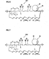
- FIG. 6 shows a band saw blade according to the fifth example of the embodiment.
- a band saw blade 23v according to the fifth example is configured almost identical to the band saw blade 23i according to the first example, and hence differences of a configuration of the band saw blade 23v from that of the band saw blade 23i will only be described.
- each concave portion 35 is rectangular in the band saw blade 23i according to the first example whereas each concave portion 35 is trapezoidal in the band saw blade 23v according to the fifth example. Even if the band saw blade 23v according to the fifth example is employed, a cutting method similar to that according to the first example can be used.
- the fifth example exhibits the same functions and advantages as those of the first example.
- band saw blade 23v can be configured so that the many concave/convex portions 33 are classified into two or more types according to the length of each concave/convex portion 33. Further, the concave portions 35 of the many concave/convex portions 33 can be classified into two or more groups according to the length of each concave portion 35.
- FIG. 7 shows a band saw blade according to the sixth example of the embodiment.
- a band saw blade 23vi according to the sixth example is configured almost identical to the band saw blade 23i according to the first example, and hence differences of a configuration of the band saw blade 23vi from that of the band saw blade 23i will only be described.
- each concave portion 35 is rectangular in the band saw blade 23i according to the first example whereas a shape of each concave portion 35 is a dovetail groove in the band saw blade 23vi according to the fifth example.
- band saw blade 23vi can be configured so that the many concave/convex portions 33 are classified into two or more types according to the length of each concave/convex portion 33. Further, the concave portions 35 of the many concave/convex portions 33 can be classified into two or more groups according to the length of each concave portion 35.
- FIG. 8 shows a band saw blade according to the seventh example of the embodiment.
- a band saw blade 23vii according to the seventh example is configured almost identical to the band saw blade 23iv according to the fourth example, and hence differences of a configuration of the band saw blade 23vii from that of the band saw blade 23iv will only be described.
- the band saw blade 23iv according to the fourth example is configured so that a gap is formed between the backup roller 29 and the bottom of the concave portion 35 when the backup roller 29 is engaged with the concave portion 35.
- the band saw blade 23vii according to the seventh example is, by contrast, configured so that the backup roller 29 contacts with the bottom of the concave portion 35 when the backup roller 29 is engaged with the concave portion 35.
- the band saw blade 23vii according to the seventh example is employed, a cutting method similar to that according to the fourth example (or first example) can be used.
- the seventh example exhibits the same functions and advantages as those of the fourth example (or first example).
- the immersion amount of the backup roller 29 with respect to the concave portion 35 when the backup roller 29 is engaged with the concave portion 35 is equal to a depth B of each of the concave portions 35, and the depth B of the concave portion 35 corresponds to the amplitude S of the vibration of the band saw blade 23vii.
- FIG. 9 shows a band saw blade according to the eighth example of the embodiment.
- a band saw blade 23viii according to the eighth example is configured almost identical to the band saw blade 23vii according to the seventh example, and hence differences of a configuration of the band saw blade 23viii from that of the band saw blade 23vii will only be described.
- the number of types of the concave portions 35 of the many concave/convex portions 33 is one in the band saw blade 23vii according to the seventh example whereas the band saw blade 23viii according to the eighth example is configured so that the concave portions 35 of many concave/convex portions 33 are classified into two types according to the depth of each concave portion 35.
- the concave portions 35 of the many concave/convex portions 33 include concave portions 35 having different depths B1 and B2.
- the band saw blade 23viii according to the eighth example is employed, a cutting method similar to that according to the seventh example (or first example) can be used.
- the eighth example exhibits the same functions and advantages as those of the eighth example (or first example).
- the concave portions 35 of the many concave/convex portions 33 include the concave portions 35 having the different depths B1 and B2
- the cutting performance (cuttability) with respect to the workpiece W can be further improved and the cutting noise can be further abated.
- the concave portions 35 of the many concave/convex portions 33 can be classified into three or more types according to the depth of each concave portion 35. Further, the many concave/convex portions 33 can be classified into two or more types according to the length of each concave/convex portion 33.
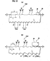
- FIG. 10 shows a band saw blade according to the ninth example of the embodiment.
- a band saw blade 23ix according to the ninth example is configured almost identical to the band saw blade 23vii according to the seventh example, and hence differences of a configuration of the band saw blade 23ix from that of the band saw blade 23vii will only be described.
- each of the concave portions 35 is rectangular in the band saw blade 23vii according to the seventh example.
- the shape of each of the concave portions 35 is a circular arc having the same radius of curvature as that of the backup roller 29 in the band saw blade 23ix according to the ninth example.
- the band saw blade 23ix according to the ninth example is employed, a cutting method similar to that according to the seventh example (or first example) can be used.
- the ninth example exhibits the same functions and advantages as those of the seventh example (or first example).
- the concave portions 35 of the many concave/convex portions 33 can be classified into two or more types according to the depth of each concave portion 35. Further, the many concave/convex portions 33 can be classified into two or more types according to the depth of each concave/convex portion 33.
- FIG. 11 shows a band saw blade according to the tenth example of the embodiment.
- a band saw blade 23x according to the tenth example is configured almost identical to the band saw blade 23vii according to the seventh example, and hence differences of a configuration of the band saw blade 23x from that of the band saw blade 23vii will only be described.
- the band saw blade 23vii according to the seventh example is configured so that the bottom of each concave portion 35 is flat whereas the band saw blade 23x according to the tenth example is configured so that the bottom of each concave portion 35 is inclined.
- the band saw blade 23x according to the tenth example is employed, a cutting method similar to that according to the seventh example (or first example) can be used.
- the tenth example exhibits the same functions and advantages as those of the seventh example (or first example). Because of the configuration so that the bottom of each concave portion 35 is inclined, the vibration of the band saw blade 23x is a smooth motion and chipping can be reduced at the tooth top of each tooth 31.
- FIGs. 12(a) and 12(b) show a band saw blade according to the eleventh example of the embodiment.
- a band saw blade 23xi according to the eleventh example is configured almost identical to the band saw blade 23i according to the first example, and hence differences of the eleventh example from the first example will only be described.
- each of the band saw guide units 25 according to the first example includes one backup roller 29 whereas each of the band saw guide units 25 according to the eleventh example includes two or three backup rollers 29.
- a center distance between the two or three backup rollers 29 divided by the length P of each concave/convex portion 33 gives two (or an integer equal to or greater than three).
- the band saw blade 23xi according to the eleventh example is employed, a cutting method similar to that according to the first example can be used.
- the eleventh example exhibits the same functions and advantages as those of the first example.
- FIG. 13(a) and 13(b) show a band saw blade according to the twelfth example of the embodiment.
- a band saw blade 23xii according to the twelfth example is configured almost identical to the band saw blade 23i according to the first example, and hence differences of the twelfth example from the first example will only be described.
- each of the band saw guide units 25 according to the first example includes the backup roller 29 whereas each of the band saw guide units 25 according to the twelfth example includes a backup chip 39 that is another backup guide.
- FIG. 14(a) shows a band saw blade according to the thirteenth example of the embodiment
- Fig. 14(b) is a view taken along a line XIVb-XIVb shown in Fig. 14(a)
- a band saw blade 23xiii according to the thirteenth example is configured almost identical to the band saw blade 23i according to the first example, and hence differences of a configuration of the band saw blade 23xiii from that of the band saw blade 23i will only be described.
- each concave portion 35 is formed by cutting or grinding in the band saw blade 23i according to the first example whereas each concave portion 35 is formed by rolling in the band saw blade 23xiii according to the thirteenth example.
- the band saw blade 23xiii according to the thirteenth example is employed, a cutting method similar to that according to the first example can be used.
- the thirteenth example exhibits the same functions and advantages as those of the first example.
- FIG. 15 shows the band saw blade according to the fourteenth example of the embodiment.
- Figs. 16(a) to 16(d) are pattern diagrams for explaining functions of the fourteenth example.
- a band saw blade 23xiv according to the fourteenth example is supported by the paired band saw guide units 25 so that the band saw blade 23xiv is able to travel similarly to the band saw blade 23i according to the first example, and the band saw blade 23xiv includes many teeth 31.
- the band saw blade 23xiv is configured so that a length P of each notch 41 is equal to or larger than the minimum pitch Tmax of the tooth top of each tooth 31 and equal to or smaller than the fourfold of the minimum pitch Tmin.
- the reason for setting the length of the notch 4 to be equal to or smaller than the fourfold of the maximum pitch Tmax of the tooth top of the tooth is as follows. If the length of the notch 41 exceeds the fourfold of the maximum pitch Tmax of the tooth top of the tooth 31, the noise value (or particularly that measured with characteristic C) increases (which is already confirmed by conducting an experiment similar to the first experiment).
- the band saw blade 23xiv is configured so that a gap is formed between the backup roller 29 and the bottom of the notch 41 when the backup roller 29 is engaged with the notch 41.
- the band saw blade 23xiv is configured so that many notches 41 are continuously formed on the back of the band saw blade 23xiv, and so that the length P of each notch 41 is equal to or smaller than the fourfold of the maximum pitch Tmax of the tooth top of the tooth 31. Due to this, by continuously engaging and disengaging the many notches 41 with and from the backup roller 29, the band saw blade 23xiv can be forcedly vibrated in a band width direction in the cutting region A. This enable alternately performing an operation for causing the teeth 31 to bite into the workpiece W as shown in Figs. 16(a) and 16(b) and an operation for causing the teeth 31 to scrape away chips Wa as shown in Figs. 16(c) and 2(d) at short intervals.
- the immersion amount of the backup roller 29 with respect to the notch 41 when the backup roller 29 is engaged with the notch 41 is the amplitude S of the vibration of the band saw blade 23xiv, and the amplitude S is equal to or higher than 0.1 mm and equal to or lower than 0.5 mm.
- the reason is as follows. If the amplitude of the vibration of the band saw blade 23xiv is lower than 0.1 mm, the cutting resistance of the workpiece W cannot be made sufficiently low. If the amplitude of the vibration of the band saw blade 23xiv is higher than 0.5 mm, the noise value (particularly the noise value measured with characteristic C) increases (which is already confirmed by conducting an experiment similar to the second experiment).
- the reason is as follows. If the frequency of the vibration of the band saw blade 23xiv is lower than 5 Hz, the cutting resistance of the workpiece W cannot be made sufficiently low (which is already confirmed by conducting an experiment similar to the third experiment).
- the operation for causing the teeth 31 to bite into the workpiece W and the operation for causing the teeth 31 to scrape away the chips Wa can be alternately performed at short intervals in the cutting region A. It is, therefore, possible to reduce the cutting length of the band saw blade 23xiv and reduce the cutting resistance of the workpiece W irrespectively of the magnitude of the workpiece W. Due to this, the cutting course deviation of the band saw blade 23xiv is suppressed, the service life of the band saw blade 23xiv is prolonged, the cutting noise is abated, and the work environment is improved.
- FIG. 17(a) and 17(b) show the band saw blade according to the fifteenth example of the embodiment.
- a band saw blade 23xv according to the fifteenth example is configured almost identical to the band saw-blade 23xiv according to the fourteenth example, and hence differences of a configuration of the band saw blade 23xv from that of the band saw blade 23xiv will only be described.
- the notches 41 are triangular and shoulders of the notches 41 are formed to be angular.
- the notches 41 are corrugated and the shoulders of the notches 41 are formed into an R shape.
- FIG. 18(a) shows the band saw blade according to the thirteenth example of the embodiment
- Fig. 18(b) is a diagram taken along a line XVIIb-XVIIb shown in Fig. 18(a)
- a band saw blade 23xvi according to the sixteenth example is configured almost identical to the band saw blade 23xiv according to the fourteenth example, and hence differences of a configuration of the band saw blade 23xvi from that of the band saw blade 23xiv will only be described.
- the band saw blade 23xvi according to the fourteenth example is configured so that a gap is formed between the backup roller 29 and the bottom of the notch 41 when the backup roller 29 is engaged with the notch 41.
- the band saw blade 23xvi according to the sixteenth example is by contrast, configured so that the backup roller 29 contacts with the bottom of the notch 41 when the backup roller 29 is engaged with the notch 41.
- each notch 41 is formed by cutting or grinding in the band saw blade 23xiv according to the fourteenth example whereas each notch 41 is formed by rolling in the band saw blade 23xvi according to the sixteenth example.
- the band saw blade 23xvi according to the sixteenth example is employed, a cutting method similar to that according to the fourteenth example can be used.
- the sixteenth example exhibits the same functions and advantages as those of the fourteenth example.
- the immersion amount of the backup roller 29 with respect to the notch 41 when the backup roller 29 is engaged with the notch 41 is equal to the depth B of the notch 41, and the depth B of the notch 41 is the amplitude S of the vibration of the band saw blade 23xvi.
Landscapes
- Engineering & Computer Science (AREA)
- Mechanical Engineering (AREA)
- Sawing (AREA)
Description
- The present invention relates to a cutting method for cutting a workpiece in a cutting region and a combination of a band saw blade and a band saw guide unit of a band saw machine.
- Conventionally, in general, a band saw machine is often used when a metal or wood workpiece is to be cut and the band saw machine includes a band saw blade as a cutting tool. The band saw blade includes many teeth including many unset teeth, many right set teeth set rightward, and many left set teeth set leftward.
- Moreover, various contrivances have been employed, e.g., changes in a height difference among the teeth, amounts of set of the right set teeth and the left set teeth, and tooth top pitches have been designed so as to improve cutting performance (cuttability) with respect to a workpiece, or to reduce noise generated at the time of cutting a workpiece (cutting noise).
- As a conventional technique relating to the present invention, Japanese Patent Brochure No.
2953767 - Prior art document
EP 0 795 369 A2 discloses a band saw blade which has less difference in cut areas of workpieces with small diameters and cut areas of workpieces with large diameters, and is capable of weakening the cutting resistance and preventing unintentional bending of a cutting line and noise generation when a workpiece, which cannot easily be cut, is cut. The band saw blade has, on the back surface of a body thereof, a wavy back surface which is changed periodically or irregularly. A plurality of imaginary curves running parallel to the wavy undulation provided for the back surface are formed opposite to the back surface. Moreover, a plurality of saw teeth having tooth tips which substantially describe the imaginary curves are formed. Thus, constant areas can be cut by the band saw blade regardless of the diameter of the workpieces required to be cut. Moreover, the cutting resistance can be weakened, and unintentional bending and noise can be prevented. - Prior art document
WO 98/35798 A1 - Meanwhile, if a workpiece as a cutting target is larger, then a cutting length of the band saw blade becomes larger and a cutting resistance of the workpiece becomes higher. Due to this, the band saw blade causes a cutting course deviation, which disadvantageously shortens a service life of the band saw blade, increases the cutting noise, and degrades the work environment.
- It is an object of the present invention is to provide a cutting method and a combination of a band saw blade and a band saw guide unit of a band saw machine capable of suppressing a cutting course deviation of the band saw blade, prolonging a service life of the band saw blade, and reducing cutting noise.
- According to the present invention said object is solved by a cutting method having the features of
independent claim 1. Moreover, said object is also solved by a combination of a band saw blade and a band saw guide unit of a band saw machine having the features ofindependent claim 3. Preferred embodiments are laid down in the dependent claims. - A first aspect provides a band saw blade supported by a band saw guide unit of a band saw machine so that the band saw blade is able to travel and including a plurality of teeth, the band saw blade comprising: a plurality of concave portions and a plurality of convex portions which are consecutively formed on a rear of the band saw blade, wherein each of the concave portions is engageable with and disengageable from a backup guide of the band saw guide unit, and each of the convex portions is adjacent to each of the concave portions, and a length of each of the concave portions and each of the convex portions is equal to or smaller than a fourfold of a maximum pitch of a tooth top of each of the teeth.
- A second aspect provides the band saw blade according to the first aspect, wherein the length of each of the concave portions and each of the convex portions is equal to or smaller than a threefold of the maximum pitch of the tooth top of each of the teeth.
- A third aspect provides the band saw blade according to the first aspect or the second aspect, wherein each of the concave portions and each of the convex portions are classified into a plurality of types according to the length of each of the concave portions and each of the convex portions.
- A fourth aspect provides the band saw blade according to any one of the first aspect to the third aspect, wherein the concave portions among the plurality of concave portions and the plurality of convex portions are classified into a plurality of types according to a length of each of the concave portions.
- A fifth aspect provides the band saw blade according to any one of the first aspect to the fourth aspect, wherein the concave portions among the plurality of concave portions and the plurality of convex portions are classified into a plurality of types according to a depth of each of the concave portions.
- According to the band saw blade of the first aspect and the fifth aspect, in a state where the band saw blade is supported by the guide unit, the band saw housing is relatively moved in a downward direction in which the band saw housing is closer to a workpiece while causing the band saw blade to circularly travel. The workpiece can be thereby cut in the cutting region (a general cutting function).
- Besides the general cutting function, the band saw blade is configured so that the many concave and convex portions are continuously formed on the back of the band saw blade, and so that the length of each concave and convex portions is equal to or smaller than the fourfold of the maximum pitch of the tooth top of the tooth. Due to this, by continuously engaging and disengaging the concave portions of the many concave and convex portions with and from the backup guide during cutting of the workpiece, the band saw blade can be forcedly vibrated in a band width direction in the cutting region. This enables alternately performing an operation for causing the teeth to bite into the workpiece and an operation for causing the teeth to scrape away chips at short intervals.
- The reason for setting the length of the concave and convex portions to be equal to or smaller than the maximum pitch of the tooth top of the tooth is as follows. As substantiated by results of a first experiment to be described later, if the length of the concave and convex portion exceeds the fourfold of the maximum pitch of the tooth top of the tooth, the noise value (or particularly the noise value measured with characteristic C) increases.
- A sixth aspect provides a band saw blade supported by a band saw guide unit of a band saw machine so that the band saw blade is able to travel and including a plurality of teeth, the band saw blade comprising: a plurality of notches consecutively formed on a rear of the band saw blade, and engageable with and disengageable from a backup guide of the band saw guide unit, wherein a length of each of the notches is equal to or smaller than a fourfold of a maximum pitch of a tooth top of each of the teeth.
- According to the band saw blade of the sixth aspect, in a state where the band saw blade is supported by the guide unit, the band saw housing is relatively moved in a downward direction in which the band saw housing is closer to the workpiece while causing the band saw blade to circularly travel. The workpiece can be thereby cut in the cutting region (a general cutting function).
- Besides the general cutting function, the band saw blade is configured so that the many notches are continuously formed on the back of the band saw blade, and so that the length of each notch is equal to or smaller than the fourfold of the maximum pitch of the tooth top of the tooth. Due to this, by continuously engaging and disengaging the many notches with and from the backup guide during cutting of the workpiece, the band saw blade can be forcedly vibrated in a band width direction in the cutting region. This enables alternately performing an operation for causing the teeth to bite into the workpiece and an operation for causing the teeth to scrape away chips at short intervals.
- A seventh aspect provides the band saw blade according to the sixth aspect, wherein the length of each of the notches is equal to or smaller than a threefold of the maximum pitch of the tooth top of each of the teeth.
- An eighth aspect provides a cutting method comprising the steps of: causing a band saw blade to continuously and circularly travel in a state where a band saw guide unit of a band saw machine supports the band saw blade; cutting a workpiece in a cutting region by relatively moving a band saw housing of the band saw machine in a cutting direction in which the band saw housing is closer to the workpiece; and forcedly vibrating the band saw blade in a band width direction in the cutting region.
- According to the cutting method of the eighth aspect, because the band saw blade is forcedly vibrated in the band width direction in the cutting region, this enable alternately performing an operation for causing the teeth to bite into the workpiece and an operation for causing the teeth to scrape away chips at short intervals.
- A ninth aspect provides the cutting method according to the eighth aspect, wherein the vibration is generated in a manner such that a concave portion among a plurality of concave portions and a plurality of convex portions which are adjacent to one another and which are consecutively formed on a rear of the band saw blade is continuously engaging with and disengaging from a backup guide provided in the band saw guide unit, and a length of each of the concave portions and each of the convex portions is equal to or smaller than a fourfold of a maximum pitch of a tooth top of each of the teeth.
- According to the cutting method of the ninth aspect, because the band saw blade is forcedly vibrated in the band width direction in the cutting region by continuously engaging and disengaging the many notches with and from the backup guide, this enable alternately performing an operation for causing the teeth to bite into the workpiece and an operation for causing the teeth to scrape away chips at short intervals.
- A tenth aspect provides the cutting method according to the eighth aspect, wherein a plurality of notches are consecutively formed on a rear of the band saw blade; the vibration is generated in a manner such that each of the notches is continuously engaging with and disengaging from a backup guide provided in the band saw guide unit, and a length of a concave and convex portion of the notch is equal to or smaller than a fourfold of a maximum pitch of a tooth top of each of a plurality of teeth provided on the band saw blade.
- According to the cutting method of the tenth aspect, because the band saw blade is forcedly vibrated in the band width direction in the cutting region by continuously engaging and disengaging the many notches with and from the backup guide, this enable alternately performing an operation for causing the teeth to bite into the workpiece and an operation for causing the teeth to scrape away chips at short intervals.
- An eleventh aspect provides the cutting method according to any one of the eighth aspect to the tenth aspect, wherein an amplitude of the vibration of the band saw blade is equal to or higher than 0.1 mm and equal to or lower than 0.5 mm.
- The reason is as follows. As substantiated by a result of a second experiment to be described later, if the amplitude of the vibration of the band saw blade is lower than 0.1 mm, the cutting resistance of the workpiece cannot be made sufficiently low. If the amplitude of the vibration of the band saw blade is higher than 0.5 mm, the noise value (or particularly the noise value measured with characteristic C) increases.
- A twelfth aspect provides the cutting method according to any one of the eighth aspect to the eleventh aspect, wherein a frequency of the vibration of the band saw blade is equal to or higher than 5 Hz.
- The reason is as follows. As substantiated by a result of a third experiment to be described later, if the frequency of the vibration of the band saw blade is lower than 5 Hz, the cutting resistance of the workpiece cannot be made sufficiently low.
- As stated so far, the operation for causing the teeth to bite into the workpiece and the operation for causing the teeth to scrape away the chips can be alternately performed at short intervals in the cutting region. It is, therefore, possible to reduce the cutting length of the band saw blade and reduce the cutting resistance of the workpiece irrespectively of a magnitude of the workpiece. Due to this, the cutting course deviation of the band saw blade is suppressed, the service life of the band saw blade is prolonged, the cutting noise is abated, and the work environment is improved.
-
-
Figs. 1 (a) and 1(b) show a band saw blade according to a first example of an embodiment; -
Figs. 2(a) to 2(d) are pattern diagrams for explaining functions of the first example of the embodiment; -
Fig. 3 shows a band saw blade according to a second example of the embodiment; -
Fig. 4 shows a band saw blade according to a third example of the embodiment; -
Figs. 5(a) and 5(b) show a band saw blade according to a fourth example of the embodiment; -
Fig. 6 shows a band saw blade according to a fifth example of the embodiment; -
Fig. 7 shows a band saw blade according to a sixth example of the embodiment; -
Fig. 8 shows a band saw blade according to a seventh example of the embodiment; -
Fig. 9 shows a band saw blade according to an eighth example of the embodiment; -
Fig. 10 shows a band saw blade according to a ninth example of the embodiment; -
Fig. 11 shows a band saw blade according to a tenth example of the embodiment; -
Figs. 12(a) and 12(b) show a band saw blade according to an eleventh example of the embodiment; -
Figs. 13(a) and 13(b) show a band saw blade according to a twelfth example of the embodiment; -
Fig. 14(a) shows a band saw blade according to a thirteenth example of the embodiment, andFig. 14(b) is a view taken along a line XIVb-XIVb shown inFig. 14(a) ; -
Fig. 15 shows a band saw blade according to a fourteenth example of the embodiment; -
Figs. 16(a) to 16(d) are pattern diagrams for explaining functions of the fourteenth example of the embodiment; -
Figs. 17(a) and 17(b) show a band saw blade according to a fifteenth example of the embodiment; -
Fig. 18(a) shows a band saw blade according to a sixteenth example of the embodiment, andFig. 18(b) is a diagram taken along a line XVIIb-XVIIb shown inFig. 18(a) ; -
Fig. 19 is a front view of a horizontal band saw machine according to the embodiment; -
Fig. 20(a) is a chart showing a relation between a length of an concave and convex portions of a band saw blade and a cutting resistance ratio when an experiment is conducted while changing the length of the concave and convex portions under predetermined conditions,Fig. 20(b) is a chart showing a relation between the length of the concave and convex portions of the band saw blade and a noise value when an experiment is conducted while changing the length of the concave and convex portion under predetermined conditions; -
Fig. 21(a) is a chart showing a relation between an amplitude of vibration of a band saw blade and a cutting resistance ratio when an experiment is conducted while changing the amplitude of vibration under predetermined conditions,Fig. 21(b) is a chart showing a relation between the amplitude of vibration of the band saw blade and a noise value when an experiment is conducted while changing the amplitude of vibration under predetermined conditions; and -
Fig. 22 is a chart showing a relation between a frequency of vibration of a band saw blade and a cutting resistance ratio when an experiment is conducted while changing the frequency under predetermined conditions. - An embodiment of the present invention will be described below with reference to the drawings. A general configuration of a horizontal band saw machine according to an embodiment will be described first with reference to
Fig. 19. Fig. 19 is a front view of the horizontal band saw machine according to the embodiment. In the following description, "horizontal" and "vertical" mean right and left and upward and downward, respectively relative to a direction of the drawings at the time of publication in a patent gazette. - As shown in
Fig. 19 , a horizontal band sawmachine 1 according to the embodiment includes a box-type support frame 3, and a table 5 supporting a workpiece W is provided on thesupport frame 3. Furthermore, afixed vice 7 and a movable vice 9, between which the workpiece W is held, are provided on thesupport frame 3 to be opposed to each other, and the movable vice 9 is movable in a horizontal direction in which the movable vice 9 is closer to or farther from thefixed vice 7 by actuation of avice cylinder 11. - Moreover, a guide post 13 (a part of which is not shown in
Fig. 19 ) stands on thesupport frame 3, and a band saw housing is provided at theguide post 13 so as to be vertically movable. To vertically move the band saw housing, a housing cylinder 15 (a part of which is not shown inFig. 19 ) that includes a verticallymovable piston rod 17 stands on thesupport frame 3. A tip end of thepiston rod 17 is coupled to an appropriate position of the band saw housing. - In the band saw housing, a
main driving wheel 19 and a drivenwheel 21 are rotatably provided, and themain driving wheel 19 is coupled to a traveling motor (not shown). An endlessband saw blade 23 is wound from themain driving wheel 19 to the drivenwheel 21. In other words, the endlessband saw blade 23 is provided in the band sawhousing 15 via themain driving wheel 19 and the drivenwheel 21. - Moreover, a pair of band saw
guide units 25 is provided in the band saw housing. The paired band sawguide units 25 supports the band sawblade 23 to enable the band sawblade 23 to travel so that a tooth top of a portion of the band sawblade 23 which portion enters a cutting region A is directed toward the workpiece W. Each band sawguide unit 25 includes a pair ofguide rollers 27 supporting a body of the band sawblade 23 so as to hold the body between theguide rollers 27, and abackup roller 29 that is one of backup guides supporting a back of the band saw blade 23 (seeFig. 1 ). Various examples of the band sawblade 23 and the band sawguide units 25 will be described below. - Accordingly, the
vice cylinder 11 is actuated, thereby moving the movable vice 9 left to be closer to thefixed vice 7 and holding the workpiece W supported on the table 5 between the movable vice 9 and thefixed vice 7. Next, the traveling motor is driven to rotate themain driving wheel 19 and the drivenwheel 21, thereby causing the band sawblade 22 to circularly travel. Further, thehousing cylinder 15 is actuated, thereby moving the band saw housing in a downward direction (a cutting direction) in which the band saw housing is closer to the workpiece W. It is thereby possible to cut the workpiece in the cutting region A. - A band saw blade according to a first example of the embodiment will be described with reference to
Figs. 1 (a), 1 (b) ,2(a) to 2(d) ,20 ,21 , and22 . -
Figs. 1(a) and 1(b) show the band saw blade according to the first example of the embodiment, andFigs. 2(a) to 2(d) are pattern diagrams for explaining functions of the first example of the embodiment.Fig. 20(a) is a chart showing a relation between a length of a concave and convex portions of the band saw blade and a cutting resistance ratio when an experiment is conducted while changing the length of the concave and convex portions of the band saw blade under predetermined conditions.Fig. 20(b) is a chart showing a relation between the length of the concave and convex portions of the band saw blade and a noise value when an experiment is conducted while changing the length of the concave and convex portions of the band saw blade under predetermined conditions. -
Fig. 21 (a) is a chart showing a relation between an amplitude of vibration of the band saw blade and the cutting resistance ratio when an experiment is conducted while changing the amplitude under predetermined conditions.Fig. 21 (b) is a chart showing a relation between the amplitude of vibration of the band saw blade and the noise value when an experiment is conducted while changing the amplitude under predetermined conditions.Fig. 22 is a chart showing a relation between a frequency of vibration of a band saw blade and a cutting resistance ratio when an experiment is conducted while changing the frequency under predetermined conditions. - As shown in
Fig. 1(a) , a band saw blade 23i according to the first example is supported by the paired band sawguide units 25 to enable the band saw blade 23i to travel as stated above and includesmany teeth 31. Themany teeth 31 include many unset teeth, many left set teeth, and many right set teeth. - Many concave/
convex portions 33 are formed continuously on the back of the band saw blade 23i, each of the concave/convex portion 33 includes a rectangular concave portion (with a depth B and a length L) 35 engageable with and disengageable from thebackup roller 29, and aconvex portion 37 adjacent to theconcave portion 35. - The band saw blade 23i is configured so that a length P of each concave/
convex portion 33 is equal to or larger than a minimum pitch Tmin of a tooth top of eachtooth 31 and equal to or smaller than a fourfold of a maximum pitch Tmax. The reason for setting the length of the concave/convex portion 33 to be equal to or smaller than the maximum pitch Tmax of the tooth top of the tooth is as follows. As substantiated by results of a first experiment shown inFigs. 20(a) and 20(b) , if the length of the concave/convex portion 33 exceeds the fourfold (52 mm) of the maximum pitch Tmax of the tooth top of thetooth 31, the noise value (or particularly the noise value measured with characteristic C) increases. - The first experiment is conducted under conditions (that a diameter of the workpiece W is 400 nm, a saw width of the band saw blade 23i is 41 mm, a band thickness is 1.3 mm, a band length is 4995 mm, the minimum pitch Tmin of the tooth top is 9.4 mm, the maximum pitch Tmax of the tooth top is 13.0 mm, a diameter of the
backup roller 29 is 34 mm, a traveling speed of the band saw blade 23i is 55 m/min, and a cutting rate is 50 cm2/min). - Moreover, the band saw blade 23i is configured so as to form a gap between the
backup roller 29 and a bottom of theconcave portion 35 when thebackup roller 29 is engaged with theconcave portion 35. Further, as shown inFig. 1(b) , to suppress stress concentration generated in corners of the bottom of theconcave portion 35, it is desirable to form the corners of the bottom of theconcave portion 35 into an R shape. - A cutting method according to the first example as well as functions of the cutting method will be described next.
- In a state where the band saw blade 23i is supported by the paired
guide units 25, the band sawhousing 15 is moved in the downward direction in which the band sawhousing 15 is closer to the workpiece W while causing the band saw blade 23i to circularly travel. The workpiece W can be thereby cut in the cutting region A (seeFig. 19 ). - The band saw blade 23i is configured so that many concave/
convex portions 33 are continuously formed on the back of the band saw blade 23i, and so that the length P of each concave/convex portion 33 is equal to or smaller than the fourfold of the maximum pitch Tmax of the tooth top of thetooth 31. Due to this, by continuously engaging and disengaging theconcave portions 35 of the many concave/convex portion 33 with and from thebackup roller 29, the band saw blade 23i can be forcedly vibrated in a band width direction in the cutting region A. This enable alternately performing an operation for causing theteeth 31 to bite into the workpiece W as shown inFigs. 2(a) and 2(b) and an operation for causing theteeth 31 to scrape away chips Wa as shown inFigs. 2(c) and 2(d) at short intervals. - In this case, an immersion amount of the
backup roller 29 with respect to theconcave portion 35 when thebackup roller 29 is engaged with theconcave portion 35 is an amplitude S of the vibration of the band saw blade 23i, and the amplitude S is equal to or higher than 0.1 mm and equal to or lower than 0.5 mm. The reason is as follows. As substantiated by a result of a second experiment shown inFigs. 21 (a) and 21(b), if the amplitude of the vibration of the band saw blade 23i is lower than 0.1 mm, the cutting resistance of the workpiece W cannot be made sufficiently low. If the amplitude of the vibration of the band saw blade 23i is higher than 0.5 mm, the noise value (or particularly the noise value measured with characteristic C) increases. Note that the second experiment is conducted under the same predetermined conditions as those of the first experiment. - Moreover, a frequency Z (Z=(1000V/60)/P) of the vibration of the band saw blade 23i specified by the length P (mm) of each concave/
convex portion 33 and the traveling speed V (m/min) of the band saw blade 23i is equal to or higher than 5 Hz. The reason is as follows. As substantiated by a result of a third experiment shown inFig. 22 , if the frequency of the vibration of the band saw blade 23i is lower than 5 Hz, the cutting resistance of the workpiece W cannot be made sufficiently low. Note that the third experiment is conducted under the same predetermined conditions as those of the first experiment. - As stated so far, according to the first example, the operation for causing the
teeth 31 to bite into the workpiece W and the operation for causing theteeth 31 to scrape away the chips Wa can be alternately performed at short intervals in the cutting region A. It is, therefore, possible to reduce the cutting length of the band saw blade 23i and reduce the cutting resistance of the workpiece W irrespectively of a magnitude of the workpiece W. Due to this, the cutting course deviation of the band saw blade 23i is suppressed, the service life of the band saw blade 23i is prolonged, the cutting noise is abated, and the work environment is improved. - A second example of the embodiment will be described with reference to
Fig. 3. Fig. 3 shows a band saw blade according to the second example of the embodiment. As shown inFig. 3 , a band saw blade 23ii according to the second example is configured almost identical to the band saw blade 23i according to the first example, and hence differences of a configuration of the band saw blade from that of the band saw blade 23i will only be described. - Namely, the many concave/
convex portions 33 are equal in length in the band saw blade 23i according to the first example whereas the band saw blade 23ii according to the second example is configured so that the many concave/convex portions 33 are classified into two types according to the length of each concave/convex portion 33. In other words, the many concave/convex portions 33 include concave/convex portions having different lengths P1 and P2. - Even if the band saw blade 23ii according to the second example is employed, a cutting method similar to that according to the first example can be used. The second example exhibits the same functions and advantages as those of the first example. Particularly because the many concave/
convex portions 33 include the concave/convex portion 33 having the different lengths P1 and P2, the cutting performance (cuttability) with respect to the workpiece can be further improved and the cutting noise can be further abated. - Note that the many concave/
convex portions 33 can be classified into three or more types according to the length of each concave/convex portion 33. - A third example of the embodiment will be described with reference to
Fig. 4. Fig. 4 shows a band saw blade according to the third example of the embodiment. As shown inFig. 4 , a band saw blade 23iii according to the third example is configured almost identical to the band saw blade 23i according to the first example, and hence differences of a configuration of the band saw blade 23iii from that of the band saw blade 23i will only be described. - Namely, the many concave/
convex portions 33 are equal in length in the band saw blade 23i according to the first example whereas the band saw blade 23iv according to the third example is configured so that theconcave portions 35 of many concave/convex portions 33 are classified into two types according to the length of eachconcave portion 35. In other words, theconcave portions 35 of the many concave/convex portions 33 includeconcave portions 35 having different lengths L1 and L2. - Even if the band saw blade 23iii according to the third example is employed, a cutting method similar to that according to the first example can be used. The third example exhibits the same functions and advantages as those of the first example. Particularly because the
concave portions 35 of the many concave/convex portions 33 include theconcave portions 35 having the different lengths L1 and L2, the cutting performance (cuttability) with respect to the workpiece W can be further improved and the cutting noise can be further abated. In this case, the vibration of the band saw blade 23iv has different amplitudes according to the different lengths of theconcave portions 35. - Note that the
concave portions 35 of the many concave/convex portions 33 can be classified into three or more types according to the length of eachconcave portion 35. - A fourth example of the embodiment will be described with reference to
Figs. 5(a) and 5(b). Figs. 5(a) and 5(b) show a band saw blade according to the fourth example of the embodiment. As shown inFigs. 5(a) and 5(b) , a band saw blade 23iv according to the fourth example is configured almost identical to the band saw blade 23i according to the first example, and hence differences of a configuration of the band saw blade 23iv from that of the band saw blade 23i will only be described. - Namely, the many concave/
convex portions 33 are equal in length in the band saw blade 23i according to the first example whereas the band saw blade 23iv according to the fourth example is configured so that the many concave/convex portions 33 are classified into two types according to the length of eachconcave portion 35. In other words, the many concave/convex portions 33 include concave/convex portion 33 having different lengths P1 and P2. As shown inFig. 5(a) , theconvex portion 37 and theconcave portion 37 adjacent to theconvex portion 37 can be equal in length (P1-L1=P2-L2). As shown inFig. 5(b) , theconvex portion 37 and anotherconcave portion 37 adjacent to theconvex portion 37 can be different in length (P1-L1≠P2-L2). - Moreover, the
concave portions 35 of the many concave/convex portions 33 are equal in length in the band saw blade 23i according to the first example. The band saw blade 23iv according to the fourth example is, by contrast, configured so that theconcave portions 35 of the many concave/convex portions 33 are classified into two types according to the length of eachconcave portion 35. In other words, theconcave portions 35 of the many concave/convex portions 33 includeconcave portions 35 having different lengths L1 and L2. - Even if the band saw blade 23iv according to the fourth example is employed, a cutting method similar to that according to the first example can be used. The fourth example exhibits the same functions and advantages as those of the first example. Particularly because the many concave/convex portions include the concave/convex portions having the different lengths P1 and P2 and the
concave portions 35 of the many concave/convex portions 33 include theconcave portions 35 having the different lengths L and L2, the cutting performance (cuttability) with respect to the workpiece W can be further improved and the cutting noise can be further abated. In this case, the vibration of the band saw blade 23iv has different amplitudes according to the different lengths of theconcave portions 35. - Note that the band saw blade 23iv can be configured so that the many concave/
convex portions 33 are classified into three or more types according to the length of each concave/convex portion 33. Further, theconcave portions 35 of the many concave/convex portion 33 can be classified into three or more groups according to the length of eachconcave portion 35. - A fifth example of the embodiment will be described with reference to
Fig. 6. Fig. 6 shows a band saw blade according to the fifth example of the embodiment. As shown inFig. 6 , a band saw blade 23v according to the fifth example is configured almost identical to the band saw blade 23i according to the first example, and hence differences of a configuration of the band saw blade 23v from that of the band saw blade 23i will only be described. - Namely, each
concave portion 35 is rectangular in the band saw blade 23i according to the first example whereas eachconcave portion 35 is trapezoidal in the band saw blade 23v according to the fifth example. Even if the band saw blade 23v according to the fifth example is employed, a cutting method similar to that according to the first example can be used. The fifth example exhibits the same functions and advantages as those of the first example. - Note that the band saw blade 23v can be configured so that the many concave/
convex portions 33 are classified into two or more types according to the length of each concave/convex portion 33. Further, theconcave portions 35 of the many concave/convex portions 33 can be classified into two or more groups according to the length of eachconcave portion 35. - A sixth example of the embodiment will be described with reference to
Fig. 7. Fig. 7 shows a band saw blade according to the sixth example of the embodiment. As shown inFig. 7 , a band saw blade 23vi according to the sixth example is configured almost identical to the band saw blade 23i according to the first example, and hence differences of a configuration of the band saw blade 23vi from that of the band saw blade 23i will only be described. - Namely, each
concave portion 35 is rectangular in the band saw blade 23i according to the first example whereas a shape of eachconcave portion 35 is a dovetail groove in the band saw blade 23vi according to the fifth example. - Even if the band saw blade 23vi according to the sixth example is employed, a cutting method similar to that according to the first example can be used. The sixth example exhibits the same functions and advantages as those of the first example.
- Note that the band saw blade 23vi can be configured so that the many concave/
convex portions 33 are classified into two or more types according to the length of each concave/convex portion 33. Further, theconcave portions 35 of the many concave/convex portions 33 can be classified into two or more groups according to the length of eachconcave portion 35. - A seventh example of the embodiment will be described with reference to
Fig. 8. Fig. 8 shows a band saw blade according to the seventh example of the embodiment. As shown inFig. 8 , a band saw blade 23vii according to the seventh example is configured almost identical to the band saw blade 23iv according to the fourth example, and hence differences of a configuration of the band saw blade 23vii from that of the band saw blade 23iv will only be described. - Namely, the band saw blade 23iv according to the fourth example is configured so that a gap is formed between the
backup roller 29 and the bottom of theconcave portion 35 when thebackup roller 29 is engaged with theconcave portion 35. The band saw blade 23vii according to the seventh example is, by contrast, configured so that thebackup roller 29 contacts with the bottom of theconcave portion 35 when thebackup roller 29 is engaged with theconcave portion 35. By so configuring, the number of contact portions of the band sawblade 23 vii with thebackup roller 29 increases, and thebackup roller 29 can receive a cutting thrust force in a dispersed manner. - Even if the band saw blade 23vii according to the seventh example is employed, a cutting method similar to that according to the fourth example (or first example) can be used. The seventh example exhibits the same functions and advantages as those of the fourth example (or first example). In this case, the immersion amount of the
backup roller 29 with respect to theconcave portion 35 when thebackup roller 29 is engaged with theconcave portion 35 is equal to a depth B of each of theconcave portions 35, and the depth B of theconcave portion 35 corresponds to the amplitude S of the vibration of the band saw blade 23vii. - An eighth example of the embodiment will be described with reference to
Fig. 9. Fig. 9 shows a band saw blade according to the eighth example of the embodiment. As shown inFig. 9 , a band saw blade 23viii according to the eighth example is configured almost identical to the band saw blade 23vii according to the seventh example, and hence differences of a configuration of the band saw blade 23viii from that of the band saw blade 23vii will only be described. - Namely, the number of types of the
concave portions 35 of the many concave/convex portions 33 is one in the band saw blade 23vii according to the seventh example whereas the band saw blade 23viii according to the eighth example is configured so that theconcave portions 35 of many concave/convex portions 33 are classified into two types according to the depth of eachconcave portion 35. In other words, theconcave portions 35 of the many concave/convex portions 33 includeconcave portions 35 having different depths B1 and B2. - Even if the band saw blade 23viii according to the eighth example is employed, a cutting method similar to that according to the seventh example (or first example) can be used. The eighth example exhibits the same functions and advantages as those of the eighth example (or first example). Particularly because the
concave portions 35 of the many concave/convex portions 33 include theconcave portions 35 having the different depths B1 and B2, the cutting performance (cuttability) with respect to the workpiece W can be further improved and the cutting noise can be further abated. In this case, the vibration of the band saw blade 23xi has different amplitudes S1(=B1) and S2(=B2) according to the different depths of theconcave portions 35. - Note that the
concave portions 35 of the many concave/convex portions 33 can be classified into three or more types according to the depth of eachconcave portion 35. Further, the many concave/convex portions 33 can be classified into two or more types according to the length of each concave/convex portion 33. - A ninth example of the embodiment will be described with reference to
Fig. 10. Fig. 10 shows a band saw blade according to the ninth example of the embodiment. As shown inFig. 10 , a band saw blade 23ix according to the ninth example is configured almost identical to the band saw blade 23vii according to the seventh example, and hence differences of a configuration of the band saw blade 23ix from that of the band saw blade 23vii will only be described. - Namely, each of the
concave portions 35 is rectangular in the band saw blade 23vii according to the seventh example. By contrast, the shape of each of theconcave portions 35 is a circular arc having the same radius of curvature as that of thebackup roller 29 in the band saw blade 23ix according to the ninth example. By so configuring, in the band saw blade 23ix according to the ninth example, thebackup roller 29 has a plane contact with theconcave portion 35, and thebackup roller 29 can receive a cutting thrust force in a dispersed manner. - Even if the band saw blade 23ix according to the ninth example is employed, a cutting method similar to that according to the seventh example (or first example) can be used. The ninth example exhibits the same functions and advantages as those of the seventh example (or first example).
- Note that the
concave portions 35 of the many concave/convex portions 33 can be classified into two or more types according to the depth of eachconcave portion 35. Further, the many concave/convex portions 33 can be classified into two or more types according to the depth of each concave/convex portion 33. - A tenth example of the embodiment will be described with reference to
Fig. 11. Fig. 11 shows a band saw blade according to the tenth example of the embodiment. As shown inFig. 11 , aband saw blade 23x according to the tenth example is configured almost identical to the band saw blade 23vii according to the seventh example, and hence differences of a configuration of the band sawblade 23x from that of the band saw blade 23vii will only be described. - Namely, the band saw blade 23vii according to the seventh example is configured so that the bottom of each
concave portion 35 is flat whereas the band sawblade 23x according to the tenth example is configured so that the bottom of eachconcave portion 35 is inclined. - Even if the band saw
blade 23x according to the tenth example is employed, a cutting method similar to that according to the seventh example (or first example) can be used. The tenth example exhibits the same functions and advantages as those of the seventh example (or first example). Because of the configuration so that the bottom of eachconcave portion 35 is inclined, the vibration of the band sawblade 23x is a smooth motion and chipping can be reduced at the tooth top of eachtooth 31. - An eleventh example of the embodiment will be described with reference to
Figs. 12(a) and 12(b). Figs. 12(a) and 12(b) show a band saw blade according to the eleventh example of the embodiment. As shown inFigs. 12(a) and 12(b) , a band saw blade 23xi according to the eleventh example is configured almost identical to the band saw blade 23i according to the first example, and hence differences of the eleventh example from the first example will only be described. - Namely, each of the band saw
guide units 25 according to the first example includes onebackup roller 29 whereas each of the band sawguide units 25 according to the eleventh example includes two or threebackup rollers 29. In this case, a center distance between the two or threebackup rollers 29 divided by the length P of each concave/convex portion 33 gives two (or an integer equal to or greater than three). By so configuring, the twobackup rollers 29 can receive a high cutting thrust force in a dispersed manner. - Even if the band saw blade 23xi according to the eleventh example is employed, a cutting method similar to that according to the first example can be used. The eleventh example exhibits the same functions and advantages as those of the first example.
- A twelfth example of the embodiment will be described with reference to
Figs. 13(a) and 13(b). Figs. 13(a) and 13(b) show a band saw blade according to the twelfth example of the embodiment. As shown inFigs. 13(a) and 13(b) , a band saw blade 23xii according to the twelfth example is configured almost identical to the band saw blade 23i according to the first example, and hence differences of the twelfth example from the first example will only be described. - Namely, each of the band saw
guide units 25 according to the first example includes thebackup roller 29 whereas each of the band sawguide units 25 according to the twelfth example includes abackup chip 39 that is another backup guide. - Even if the band saw blade 23xii according to the twelfth example is employed, a cutting method similar to that according to the first example can be used. The twelfth example exhibits the same functions and advantages as those of the first example.
- A thirteenth example of the embodiment will be described with reference to
Figs. 14(a) and 14(b). Fig. 14(a) shows a band saw blade according to the thirteenth example of the embodiment, andFig. 14(b) is a view taken along a line XIVb-XIVb shown inFig. 14(a) . As shown inFigs. 14(a) and 14(b) , a band saw blade 23xiii according to the thirteenth example is configured almost identical to the band saw blade 23i according to the first example, and hence differences of a configuration of the band saw blade 23xiii from that of the band saw blade 23i will only be described. - Namely, each
concave portion 35 is formed by cutting or grinding in the band saw blade 23i according to the first example whereas eachconcave portion 35 is formed by rolling in the band saw blade 23xiii according to the thirteenth example. - Even if the band saw blade 23xiii according to the thirteenth example is employed, a cutting method similar to that according to the first example can be used. The thirteenth example exhibits the same functions and advantages as those of the first example.
- A band saw blade according to a fourteenth example of the embodiment will be described with reference to
Figs. 15 and16(a) to 16(d).Fig. 15 shows the band saw blade according to the fourteenth example of the embodiment.Figs. 16(a) to 16(d) are pattern diagrams for explaining functions of the fourteenth example. As shown inFig. 15 , a band saw blade 23xiv according to the fourteenth example is supported by the paired band sawguide units 25 so that the band saw blade 23xiv is able to travel similarly to the band saw blade 23i according to the first example, and the band saw blade 23xiv includesmany teeth 31. - Many triangular notches (with a depth B) 41 engageable with and disengageable from the
backup roller 29 are continuously formed on the back of the band saw blade 23xiv. - Furthermore, the band saw blade 23xiv is configured so that a length P of each
notch 41 is equal to or larger than the minimum pitch Tmax of the tooth top of eachtooth 31 and equal to or smaller than the fourfold of the minimum pitch Tmin. The reason for setting the length of the notch 4 to be equal to or smaller than the fourfold of the maximum pitch Tmax of the tooth top of the tooth is as follows. If the length of thenotch 41 exceeds the fourfold of the maximum pitch Tmax of the tooth top of thetooth 31, the noise value (or particularly that measured with characteristic C) increases (which is already confirmed by conducting an experiment similar to the first experiment). - Moreover, the band saw blade 23xiv is configured so that a gap is formed between the
backup roller 29 and the bottom of thenotch 41 when thebackup roller 29 is engaged with thenotch 41. - A cutting method according to the fourteenth example as well as functions of the cutting method will be described next. In a state where the band saw blade 23xiv is supported by the paired
guide units 25, the band sawhousing 15 is moved in a downward direction in which the band sawhousing 15 is closer to the workpiece W while causing the band saw blade 23xiv to circularly travel. The workpiece W can be thereby cut in the cutting region A (seeFig. 19 ). - The band saw blade 23xiv is configured so that
many notches 41 are continuously formed on the back of the band saw blade 23xiv, and so that the length P of eachnotch 41 is equal to or smaller than the fourfold of the maximum pitch Tmax of the tooth top of thetooth 31. Due to this, by continuously engaging and disengaging themany notches 41 with and from thebackup roller 29, the band saw blade 23xiv can be forcedly vibrated in a band width direction in the cutting region A. This enable alternately performing an operation for causing theteeth 31 to bite into the workpiece W as shown inFigs. 16(a) and 16(b) and an operation for causing theteeth 31 to scrape away chips Wa as shown inFigs. 16(c) and2(d) at short intervals. - In this case, the immersion amount of the
backup roller 29 with respect to thenotch 41 when thebackup roller 29 is engaged with thenotch 41 is the amplitude S of the vibration of the band saw blade 23xiv, and the amplitude S is equal to or higher than 0.1 mm and equal to or lower than 0.5 mm. The reason is as follows. If the amplitude of the vibration of the band saw blade 23xiv is lower than 0.1 mm, the cutting resistance of the workpiece W cannot be made sufficiently low. If the amplitude of the vibration of the band saw blade 23xiv is higher than 0.5 mm, the noise value (particularly the noise value measured with characteristic C) increases (which is already confirmed by conducting an experiment similar to the second experiment). - Moreover, the frequency Z(Z=(1000V/60)/P) of the vibration of the band saw blade 23xiv specified by the length P (mm) of the
notch 41 and the traveling speed V (m/min) of the band saw blade 23xiv is equal to or higher than 5 Hz. The reason is as follows. If the frequency of the vibration of the band saw blade 23xiv is lower than 5 Hz, the cutting resistance of the workpiece W cannot be made sufficiently low (which is already confirmed by conducting an experiment similar to the third experiment). - As stated so far, according to the fourteenth example, the operation for causing the
teeth 31 to bite into the workpiece W and the operation for causing theteeth 31 to scrape away the chips Wa can be alternately performed at short intervals in the cutting region A. It is, therefore, possible to reduce the cutting length of the band saw blade 23xiv and reduce the cutting resistance of the workpiece W irrespectively of the magnitude of the workpiece W. Due to this, the cutting course deviation of the band saw blade 23xiv is suppressed, the service life of the band saw blade 23xiv is prolonged, the cutting noise is abated, and the work environment is improved. - A band saw blade according to a fifteenth example of the embodiment will be briefly described with reference to
Figs. 17(a) and 17(b). Figs. 17(a) and 17(b) show the band saw blade according to the fifteenth example of the embodiment. As shown inFigs. 17(a) and 17(b) , a band saw blade 23xv according to the fifteenth example is configured almost identical to the band saw-blade 23xiv according to the fourteenth example, and hence differences of a configuration of the band saw blade 23xv from that of the band saw blade 23xiv will only be described. - Namely, in the band saw blade 23xiv according to the fourteenth example, the
notches 41 are triangular and shoulders of thenotches 41 are formed to be angular. In the band saw blade 23xv according to the fifteenth example, by contrast, thenotches 41 are corrugated and the shoulders of thenotches 41 are formed into an R shape. - Even if the band saw blade 23xv according to the fifteenth example is employed, a cutting method similar to that according to the fourteenth example can be used. The fifteenth example exhibits the same functions and advantages as those of the fourteenth example.
- A band saw blade according to a sixteenth example of the embodiment will be described with reference to
Figs. 18(a) and 18(b). Fig. 18(a) shows the band saw blade according to the thirteenth example of the embodiment, andFig. 18(b) is a diagram taken along a line XVIIb-XVIIb shown inFig. 18(a) . As shown inFigs. 18(a) and 18(b) , a band saw blade 23xvi according to the sixteenth example is configured almost identical to the band saw blade 23xiv according to the fourteenth example, and hence differences of a configuration of the band saw blade 23xvi from that of the band saw blade 23xiv will only be described. - Namely, the band saw blade 23xvi according to the fourteenth example is configured so that a gap is formed between the
backup roller 29 and the bottom of thenotch 41 when thebackup roller 29 is engaged with thenotch 41. The band saw blade 23xvi according to the sixteenth example is by contrast, configured so that thebackup roller 29 contacts with the bottom of thenotch 41 when thebackup roller 29 is engaged with thenotch 41. By so configuring, the number of contact portions of the band saw blade 23xvi with thebackup roller 29 increases, and thebackup roller 29 can receive a cutting thrust force in a dispersed manner. - Moreover, each
notch 41 is formed by cutting or grinding in the band saw blade 23xiv according to the fourteenth example whereas eachnotch 41 is formed by rolling in the band saw blade 23xvi according to the sixteenth example. - Even if the band saw blade 23xvi according to the sixteenth example is employed, a cutting method similar to that according to the fourteenth example can be used. The sixteenth example exhibits the same functions and advantages as those of the fourteenth example. In this case, the immersion amount of the
backup roller 29 with respect to thenotch 41 when thebackup roller 29 is engaged with thenotch 41 is equal to the depth B of thenotch 41, and the depth B of thenotch 41 is the amplitude S of the vibration of the band saw blade 23xvi.
Claims (8)
- A cutting method comprising the steps of:causing a band saw blade to continuously and circularly run in such a manner that the band saw blade is supported by a band saw guide unit (25) of a band saw machine;cutting a workpiece in a cutting region by relatively moving a band saw housing of the band saw machine in a cutting direction in which the band saw housing is approaching to the workpiece; andforcedly vibrating the band saw blade in a band width direction in the cutting region, thereby generating vibration;wherein a plurality of concave/convex portions (33) or a plurality of notches (41) are consecutively formed on a rear of the band saw blade; each of the plurality of concave/convex portions (33) including a concave portion (35) and a convex portion (37) arranged adjacent to one another;the vibration is generated by engaging with and disengaging from the concave portions (35) of the plurality of concave/convex portions (33) or the plurality of notches (41) from a backup guide (29,39) provided in the band saw guide unit (25);a length (P) of each of the plurality of concave/convex portions (33) or each of the plurality of notches (41) is equal to or less than four times a maximum pitch (Tmax) of a tooth top of the teeth (31) and equal to or greater than a minimum pitch (Tmin) of the tooth top of the teeth (31); andeach of the plurality of concave/convex portions (33) or each of the plurality of notches (41) has such a size that an immersion amount of the backup guide (29, 39) with respect to the concave portion (35) or the notch (41) when the backup guide (29, 39) is engaged with the concave portion (35) or the notch (41) defines an amplitude of the vibration in the band width direction of the band saw blade which is equal to or higher than 0.1 mm and equal to or lower than 0.5 mm.
- The cutting method according to claim 1, wherein a frequency of the vibration of the band saw blade is equal to or higher than 5 Hz.
- A combination of a band saw blade and a band saw guide unit of a band saw machine, the band saw blade is provided with a plurality of teeth (31), the band saw blade being able to be slidably supported by a band saw guide unit (25) of a band saw machine, comprising:a plurality of concave/convex portions (33) that are consecutively formed on a rear of the band saw blade, wherein each of concave/convex portions (33) includes a concave portion (35) and a convex portion (37) arranged adjacent to one another, and the band saw blade is adapted for generating a vibration in a band width direction of the band saw blade in a manner such that a backup guide (29, 39) provided in the band saw guide unit (25) is engaging with and disengaging from the concave portions (35) of the plurality of concave/convex portions (33);each of the plurality of concave/convex portions (33) is equal to or less than four times a maximum pitch (Tmax) of a tooth top of the teeth (31) and equal to or greater than a minimum pitch (Tmin) of the tooth top of the teeth (31); andeach of the plurality of concave/convex portions (33) has such a size that an immersion amount of the backup guide (29, 39) with respect to the concave portion (35) when the backup guide (29, 39) is engaged with the concave portion (35) defines an amplitude of the vibration in the band width direction of the band saw blade which is equal to or higher than 0.1 mm and equal to or lower than 0.5 mm, orthe band saw blade is provided with a plurality of teeth (31), the band saw blade being able to be slidably supported by a band saw guide unit (25) of a band saw machine, comprising:a plurality of notches (41) that are consecutively formed on a rear of the band saw blade, wherein and the band saw blade is adapted for generating a vibration in a band width direction of the band saw blade in a manner such that a backup guide (29, 39) provided in the band saw guide unit (25) is engaging with and disengaging from the plurality of notches (41) from a backup guide (29,39) provided in the band saw guide unit (25);a length (P) of each of the plurality of notches (41) is equal to or less than four times a maximum pitch (Tmax) of a tooth top of the teeth (31) and equal to or greater than a minimum pitch (Tmin) of the tooth top of the teeth (31); andeach of the plurality of notches (41) has such a size that an immersion amount of the backup guide (29, 39) with respect to the notch (41) when the backup guide (29, 39) is engaged with the notch (41) defines an amplitude of the vibration in the band width direction of the band saw blade which is equal to or higher than 0.1 mm and equal to or lower than 0.5 mm.
- The combination according to claim 3, wherein the band saw blade has a plurality of concave/convex portions (33), wherein the length (P) of each of the plurality of concave/convex portions (33) is equal to or less than three times the maximum pitch (Tmax) of the tooth top of the teeth (31).
- The combination according to claim 3, wherein the band saw blade has a plurality of concave/convex portions (33), wherein each of the concave portions (35) and each of the convex portions (37) are classified into a plurality of types according to the length of each of the concave portions (35) and each of the convex portions (37).
- The combination according to claim 3, wherein the band saw blade has a plurality of concave/convex portions (33), wherein the concave portions (35) among the plurality of concave portions (35) and the plurality of convex portions (37) are classified into a plurality of types according to a length of each of the concave portions (35).
- The combination according to claim 3, wherein the band saw blade has a plurality of concave/convex portions (33), wherein the concave portions (35) among the plurality of concave portions (35) and the plurality of convex portions (37) are classified into a plurality of types according to a depth of each of the concave portions (35).
- The combination according to claim 3, wherein the band saw blade has a plurality of notches (41), wherein the length (P) of each of the plurality of notches (41) is equal to or less than three times the maximum pitch (Tmax) of the tooth top of the teeth (31).
Applications Claiming Priority (3)
| Application Number | Priority Date | Filing Date | Title |
|---|---|---|---|
| JP2004239864 | 2004-08-19 | ||
| JP2005205905A JP4102817B2 (en) | 2004-08-19 | 2005-07-14 | Band saw blade |
| PCT/JP2005/015056 WO2006019129A1 (en) | 2004-08-19 | 2005-08-18 | Band saw blade and cutting method |
Publications (3)
| Publication Number | Publication Date |
|---|---|
| EP1795289A1 EP1795289A1 (en) | 2007-06-13 |
| EP1795289A4 EP1795289A4 (en) | 2013-05-08 |
| EP1795289B1 true EP1795289B1 (en) | 2015-12-23 |
Family
ID=35907512
Family Applications (1)
| Application Number | Title | Priority Date | Filing Date |
|---|---|---|---|
| EP05772655.6A Ceased EP1795289B1 (en) | 2004-08-19 | 2005-08-18 | Cutting method and combination of a band saw blade and a band saw guide unit of a band saw machine |
Country Status (4)
| Country | Link |
|---|---|
| US (1) | US8051756B2 (en) |
| EP (1) | EP1795289B1 (en) |
| JP (1) | JP4102817B2 (en) |
| WO (1) | WO2006019129A1 (en) |
Families Citing this family (29)
| Publication number | Priority date | Publication date | Assignee | Title |
|---|---|---|---|---|
| DE10063567A1 (en) * | 2000-12-20 | 2002-07-04 | Scintilla Ag | sawblade |
| JP5238406B2 (en) * | 2008-08-20 | 2013-07-17 | 株式会社アマダ | Band saw blade |
| CN102548697B (en) * | 2009-07-27 | 2015-08-19 | 艾温工业工具公司 | There is saw blade and the correlation technique of single-stage and multistage setting model in pitch model |
| EP2564966B1 (en) | 2010-04-22 | 2017-04-12 | Milwaukee Electric Tool Corporation | Saw blade |
| US10189099B2 (en) | 2010-04-22 | 2019-01-29 | Milwaukee Electric Tool Corporation | Saw Blade |
| DE102010028748A1 (en) * | 2010-05-07 | 2011-11-10 | Robert Bosch Gmbh | sawblade |
| US9375796B2 (en) | 2010-05-07 | 2016-06-28 | Irwin Industrial Tool Company | Saw blade with robust tooth form |
| USD642028S1 (en) | 2010-05-21 | 2011-07-26 | Irwin Industrial Tool Company | Reciprocating saw blade |
| US20120042765A1 (en) | 2010-08-20 | 2012-02-23 | Kazda Austin J | Reciprocating saw blade |
| USD841417S1 (en) | 2011-04-22 | 2019-02-26 | Milwaukee Electric Tool Corporation | Saw blade |
| JP5879192B2 (en) | 2012-05-02 | 2016-03-08 | 株式会社アマダホールディングス | Band saw machine |
| SE538438C2 (en) * | 2012-07-03 | 2016-06-28 | Kapman Ab | Saw blades and ways to design a trailing edge on a saw blade |
| US9370834B2 (en) | 2013-03-14 | 2016-06-21 | Irwin Industrial Tool Company | Saw blade with feed limiter |
| US20140259699A1 (en) * | 2013-03-14 | 2014-09-18 | Benjamin Yang | Flexible saw blades and methods for curvature cutting |
| CA2845968C (en) | 2013-03-14 | 2016-07-26 | Irwin Industrial Tool Company | Reciprocating saw blade with curved cutting edge |
| DE102013110120A1 (en) * | 2013-09-13 | 2015-03-19 | WIKUS-Sägenfabrik Wilhelm H. Kullmann GmbH & Co. KG | Saw band with profiled strap back |
| USD725450S1 (en) * | 2013-11-13 | 2015-03-31 | Irwin Industrial Tool Company | Reciprocating saw blade |
| USD732914S1 (en) * | 2013-11-13 | 2015-06-30 | Irwin Industrial Tool Company | Reciprocating saw blade |
| JP2016083767A (en) | 2014-10-24 | 2016-05-19 | アーウィン インダストリアル トゥール カンパニー | Band saw blade with repeating back edge pattern and related method |
| US20160303747A1 (en) | 2015-04-14 | 2016-10-20 | Darex, Llc | Cutting Edge with Microscopically Sized Channels to Enhance Cutting Performance |
| IT201600109228A1 (en) * | 2016-10-28 | 2018-04-28 | Francesco Arrighi | MACHINE SAW WITH CONFORMED TAPE BLADE |
| CN110650829A (en) | 2017-05-16 | 2020-01-03 | 米沃奇电动工具公司 | Saw blade |
| US10537951B2 (en) | 2017-08-16 | 2020-01-21 | Black & Decker Inc. | Band saw blade for cutting structural workpieces |
| US10814413B2 (en) * | 2017-09-05 | 2020-10-27 | Simonds Saw Llc | Saw blade having ramp elements with a variable curve geometry |
| US10765060B2 (en) * | 2018-06-04 | 2020-09-08 | Deere & Company | Crop cutting knives for agricultural combine harvester |
| AT523011B1 (en) * | 2019-10-08 | 2023-05-15 | Gebrueder Busatis Ges M B H | Knife arrangement for agricultural machines |
| JP7535132B2 (en) * | 2020-06-05 | 2024-08-15 | ザ エムケー モールス カンパニー | Bandsaw with improved trailing edge |
| JP7482713B2 (en) * | 2020-08-07 | 2024-05-14 | 株式会社アマダ | Method for manufacturing hoop material and band saw blade |
| US11440111B2 (en) * | 2020-08-17 | 2022-09-13 | Bmic Llc | Method of using a blade configured to reduce residual foam dust |
Family Cites Families (31)
| Publication number | Priority date | Publication date | Assignee | Title |
|---|---|---|---|---|
| US239710A (en) * | 1881-04-05 | Crosscut-saw | ||
| US1850478A (en) * | 1930-11-06 | 1932-03-22 | Atlantic Service Company Inc | Saw |
| US2152906A (en) * | 1936-08-12 | 1939-04-04 | Harry G Miller | Band saw guide |
| DE1119081B (en) * | 1959-09-03 | 1961-12-07 | Rudolf Alber | Bandsaw blade |
| US3220446A (en) * | 1963-12-20 | 1965-11-30 | Walter H Burkey | Band saw guide |
| AT301836B (en) * | 1969-05-28 | 1972-09-25 | Busatis Geb Gmbh | Saw blade |
| SE7712285L (en) * | 1976-11-01 | 1978-05-02 | Wallace Murray Corp | BAND SAW SHEET |
| US4195543A (en) * | 1976-11-12 | 1980-04-01 | Wallace Murray Canada Limited | Band saw |
| US4205571A (en) * | 1977-10-17 | 1980-06-03 | Millo Bertini | Saw blade construction |
| US4179966A (en) * | 1978-01-30 | 1979-12-25 | Oscar Ginnow | Sensor for determining band saw deflection and for guiding the band saw blade |
| US4179967A (en) * | 1978-08-28 | 1979-12-25 | Stanadyne, Inc. | Variable tooth saw blade |
| US4189968A (en) * | 1978-08-30 | 1980-02-26 | Dayco Corporation | Mobius strip bandsaw blade |
| JPS6031608B2 (en) | 1981-11-12 | 1985-07-23 | 株式会社 アマダ | Band saw blade for difficult-to-cut materials |
| US4423653A (en) * | 1982-10-15 | 1984-01-03 | American Saw & Mfg. Company | Band saw blade construction |
| US4766790A (en) * | 1984-02-06 | 1988-08-30 | Harris Gerald R | Band saw apparatus and method |
| JPS6195815A (en) * | 1984-10-16 | 1986-05-14 | Hitachi Koki Haramachi:Kk | Saw element peripheral speed control device for band sawing machine |
| US5201110A (en) * | 1986-08-22 | 1993-04-13 | Bane Marvin L | Pallet dismantler |
| GB2226274B (en) * | 1988-12-07 | 1993-06-09 | Amada Co Ltd | Saw blade |
| PL324206A1 (en) * | 1995-03-23 | 1998-05-11 | American Saw & Mfg | Synchronised saw teeth of variable design |
| DE69717699T2 (en) * | 1996-03-11 | 2003-09-18 | Amada Co., Ltd. | band saw blade |
| JP3265217B2 (en) | 1996-03-11 | 2002-03-11 | 株式会社アマダ | Band saw blade |
| WO1998035798A1 (en) * | 1997-02-14 | 1998-08-20 | Sandvik Aktiebolag (Publ) | Bandsaw blade |
| US7036415B2 (en) * | 1997-05-08 | 2006-05-02 | Amada Company, Limited | Band saw blade |
| WO1998056550A1 (en) * | 1997-06-11 | 1998-12-17 | Bauer Egil Kaare | Bandsaw |
| US6463836B1 (en) * | 1999-02-01 | 2002-10-15 | Howard L. Snodgrass, Jr. | Guide for band saws |
| US6276248B1 (en) * | 1999-11-05 | 2001-08-21 | American Saw & Manufacturing Company | Band saw blade having reduced noise and uniform tooth loading characteristics |
| IT251001Y1 (en) * | 2000-09-07 | 2003-10-22 | Eliseo Giovannini | BAND SAW WITH ANTI-SLIP VEHICLES. |
| AU2002224076A1 (en) * | 2000-11-27 | 2002-06-03 | Amada Company Limited | Saw blade |
| AU2003271157A1 (en) * | 2002-10-10 | 2004-05-04 | Amada Company, Limited | Saw blade |
| JP3949693B2 (en) * | 2004-07-26 | 2007-07-25 | 株式会社アマダ | Band saw machine |
| US7520202B2 (en) * | 2006-11-09 | 2009-04-21 | Oav Equipment & Tools, Inc. | Guiding device for saw blade of band saw |
-
2005
- 2005-07-14 JP JP2005205905A patent/JP4102817B2/en not_active Expired - Fee Related
- 2005-08-18 WO PCT/JP2005/015056 patent/WO2006019129A1/en active Application Filing
- 2005-08-18 EP EP05772655.6A patent/EP1795289B1/en not_active Ceased
- 2005-08-18 US US11/573,974 patent/US8051756B2/en not_active Expired - Fee Related
Also Published As
| Publication number | Publication date |
|---|---|
| JP2006082217A (en) | 2006-03-30 |
| EP1795289A1 (en) | 2007-06-13 |
| US8051756B2 (en) | 2011-11-08 |
| US20080121079A1 (en) | 2008-05-29 |
| JP4102817B2 (en) | 2008-06-18 |
| WO2006019129A1 (en) | 2006-02-23 |
| EP1795289A4 (en) | 2013-05-08 |
Similar Documents
| Publication | Publication Date | Title |
|---|---|---|
| EP1795289B1 (en) | Cutting method and combination of a band saw blade and a band saw guide unit of a band saw machine | |
| EP0726829B1 (en) | Improved band saw blade | |
| KR100348777B1 (en) | saw blade | |
| EP0814935A1 (en) | Synchronized variable tooth arrangements for saws | |
| JP6349090B2 (en) | Saw blade | |
| JP4529031B2 (en) | Band saw machine | |
| JP2011240463A (en) | Bar cutting machine | |
| WO2017099108A1 (en) | Method for producing bandsaw blade that lengthens service life of barrel member, and bandsaw blade | |
| JP6733022B2 (en) | Grooving device using wire saw and its method | |
| JP4529032B2 (en) | Band saw blade and cutting method | |
| JPH1044142A (en) | Multiple wire saw | |
| JP2004195609A (en) | Saw blade | |
| CN101357408B (en) | Workpiece cutting method and band-saw machine | |
| EP1586401A1 (en) | Bandsaw blade and method of manufacturing bandsaw blade | |
| JP4408425B2 (en) | Band saw and method of manufacturing band saw | |
| EP1234629A1 (en) | Device for reciprocating a band saw perpendicular to its longitudinal axis | |
| JP2023529147A (en) | Bandsaw with improved trailing edge | |
| RU2464166C1 (en) | Method of sawing hard stone rock | |
| CN215032757U (en) | Section bar puncher | |
| EP1481782A1 (en) | Cutting tool for stone materials | |
| JP2018001408A (en) | Band saw blade | |
| JPH0691595A (en) | Cutting method of plastic molding | |
| JP4454656B2 (en) | Metal bond band saw | |
| JPS63300874A (en) | Endless cutter | |
| JPH0569225A (en) | Endless cutter and cutting device |
Legal Events
| Date | Code | Title | Description |
|---|---|---|---|
| PUAI | Public reference made under article 153(3) epc to a published international application that has entered the european phase |
Free format text: ORIGINAL CODE: 0009012 |
|
| 17P | Request for examination filed |
Effective date: 20070316 |
|
| AK | Designated contracting states |
Kind code of ref document: A1 Designated state(s): DE |
|
| DAX | Request for extension of the european patent (deleted) | ||
| RBV | Designated contracting states (corrected) |
Designated state(s): DE |
|
| A4 | Supplementary search report drawn up and despatched |
Effective date: 20130410 |
|
| RIC1 | Information provided on ipc code assigned before grant |
Ipc: B23D 61/12 20060101AFI20130404BHEP |
|
| 17Q | First examination report despatched |
Effective date: 20131204 |
|
| GRAP | Despatch of communication of intention to grant a patent |
Free format text: ORIGINAL CODE: EPIDOSNIGR1 |
|
| INTG | Intention to grant announced |
Effective date: 20150625 |
|
| GRAS | Grant fee paid |
Free format text: ORIGINAL CODE: EPIDOSNIGR3 |
|
| GRAA | (expected) grant |
Free format text: ORIGINAL CODE: 0009210 |
|
| AK | Designated contracting states |
Kind code of ref document: B1 Designated state(s): DE |
|
| REG | Reference to a national code |
Ref country code: DE Ref legal event code: R096 Ref document number: 602005048133 Country of ref document: DE |
|
| REG | Reference to a national code |
Ref country code: DE Ref legal event code: R097 Ref document number: 602005048133 Country of ref document: DE |
|
| PLBE | No opposition filed within time limit |
Free format text: ORIGINAL CODE: 0009261 |
|
| STAA | Information on the status of an ep patent application or granted ep patent |
Free format text: STATUS: NO OPPOSITION FILED WITHIN TIME LIMIT |
|
| 26N | No opposition filed |
Effective date: 20160926 |
|
| PGFP | Annual fee paid to national office [announced via postgrant information from national office to epo] |
Ref country code: DE Payment date: 20210819 Year of fee payment: 17 |
|
| REG | Reference to a national code |
Ref country code: DE Ref legal event code: R119 Ref document number: 602005048133 Country of ref document: DE |
|
| PG25 | Lapsed in a contracting state [announced via postgrant information from national office to epo] |
Ref country code: DE Free format text: LAPSE BECAUSE OF NON-PAYMENT OF DUE FEES Effective date: 20230301 |