EP1795146A1 - Pushing device for tooth restoration material in capsule - Google Patents
Pushing device for tooth restoration material in capsule Download PDFInfo
- Publication number
- EP1795146A1 EP1795146A1 EP06025370A EP06025370A EP1795146A1 EP 1795146 A1 EP1795146 A1 EP 1795146A1 EP 06025370 A EP06025370 A EP 06025370A EP 06025370 A EP06025370 A EP 06025370A EP 1795146 A1 EP1795146 A1 EP 1795146A1
- Authority
- EP
- European Patent Office
- Prior art keywords
- ratchet
- pressing
- piston rod
- capsule
- lever
- Prior art date
- Legal status (The legal status is an assumption and is not a legal conclusion. Google has not performed a legal analysis and makes no representation as to the accuracy of the status listed.)
- Granted
Links
- 239000000463 material Substances 0.000 title claims abstract description 193
- 239000002775 capsule Substances 0.000 title claims abstract description 186
- 238000003825 pressing Methods 0.000 claims abstract description 194
- 230000003449 preventive effect Effects 0.000 claims abstract description 142
- 230000006835 compression Effects 0.000 claims abstract description 94
- 238000007906 compression Methods 0.000 claims abstract description 94
- 229920003002 synthetic resin Polymers 0.000 claims description 7
- 239000000057 synthetic resin Substances 0.000 claims description 7
- 238000009751 slip forming Methods 0.000 claims description 5
- 239000000843 powder Substances 0.000 abstract description 47
- 239000007788 liquid Substances 0.000 description 28
- 238000002156 mixing Methods 0.000 description 14
- 238000004898 kneading Methods 0.000 description 10
- 230000001965 increasing effect Effects 0.000 description 8
- 238000000034 method Methods 0.000 description 6
- 230000003247 decreasing effect Effects 0.000 description 3
- 239000003479 dental cement Substances 0.000 description 3
- 230000000149 penetrating effect Effects 0.000 description 3
- 239000000203 mixture Substances 0.000 description 2
- 238000005192 partition Methods 0.000 description 2
- 229920006324 polyoxymethylene Polymers 0.000 description 2
- 238000002360 preparation method Methods 0.000 description 2
- 229930040373 Paraformaldehyde Natural products 0.000 description 1
- 239000012141 concentrate Substances 0.000 description 1
- 208000002925 dental caries Diseases 0.000 description 1
- 150000002222 fluorine compounds Chemical class 0.000 description 1
- 230000001939 inductive effect Effects 0.000 description 1
- 230000007257 malfunction Effects 0.000 description 1
- 239000002184 metal Substances 0.000 description 1
- -1 polyoxymethylene Polymers 0.000 description 1
- 229920005989 resin Polymers 0.000 description 1
- 239000011347 resin Substances 0.000 description 1
- 239000002210 silicon-based material Substances 0.000 description 1
- 239000002689 soil Substances 0.000 description 1
Images


Classifications
-
- A—HUMAN NECESSITIES
- A61—MEDICAL OR VETERINARY SCIENCE; HYGIENE
- A61C—DENTISTRY; APPARATUS OR METHODS FOR ORAL OR DENTAL HYGIENE
- A61C5/00—Filling or capping teeth
- A61C5/60—Devices specially adapted for pressing or mixing capping or filling materials, e.g. amalgam presses
- A61C5/62—Applicators, e.g. syringes or guns
Landscapes
- Health & Medical Sciences (AREA)
- Oral & Maxillofacial Surgery (AREA)
- Dentistry (AREA)
- Epidemiology (AREA)
- Life Sciences & Earth Sciences (AREA)
- Animal Behavior & Ethology (AREA)
- General Health & Medical Sciences (AREA)
- Public Health (AREA)
- Veterinary Medicine (AREA)
- Dental Tools And Instruments Or Auxiliary Dental Instruments (AREA)
- Dental Preparations (AREA)
Abstract
Description
- The present invention relates to a pushing device for a tooth restoration material mixed and kneaded in a capsule, which are for pushing out a desired amount of the mixed and kneaded tooth restoration material toward a treating portion of a patient. A capsule for a tooth restoration material is mounted on the pushing device, and the tooth restoration material is made by mixing and kneading predetermined amounts of a powder component and a liquid component, which are isolatedly housed in the capsule so as to constitute the tooth restoration material such as dental cement or the like.
- As a dental treatment method widely used for filling the tooth restoration material such as dental cement or the like to a caries portion of a tooth, there is a treatment method comprising the steps of isolatedly housing predetermined amounts of a powder component and a liquid component constituting the tooth restoration material in one capsule for the tooth restoration material; destroying a partition wall for isolating the powder component and the liquid component in the capsule for a tooth restoration material immediately before using the tooth restoration material; mounting the capsule for a tooth restoration material on an automatic kneading device so as to mix and knead the powder component and the liquid component immediately after destroying the partition wall; setting the capsule for a tooth restoration material to a pushing device for the tooth restoration material; and pushing out a desired amount of the mixed and kneaded tooth restoration material from a nozzle of the capsule for a tooth restoration material toward a treating portion of a patient.
- As for the capsule for a tooth restoration material used for such the treatment method, for example, there is a capsule for mixing and kneading a tooth restoration material therein, where the tooth restoration material consists of fixed amounts of two components, that is, a powder component and a liquid component measured in advance, and directly administering the mixture to a portion of a tooth of patient to be restored, comprising a cylinder-shaped capsule body having a mixing compartment for housing the powder component and provided with a first opening forming part on a center axis at an end thereof for forming a mixture outlet hole; a liquid cup having a liquid component housing room therein for housing the liquid component and provided with a second opening forming part on a center axis at an end thereof for forming an outlet hole for the liquid component, where the liquid cup is fitted over the cylinder-shaped portion for forming the mixing compartment of the capsule body and provided with a projection stopper on an outer surface thereof near a rear end thereof; a plunger having a rod-shaped projection for tearing the second opening forming part of the liquid cup and the first opening forming part of the capsule body and being fitted over the cylinder-shaped portion in the liquid cup; and a nozzle having an rear end, which has a shape corresponding to the front end of the capsule body and being connected to the front end of the capsule body. The projection stopper has such a size as prevent to easily take the liquid cup into the capsule body when tearing the second opening forming part so as to form the outlet hole for the liquid component, but does not prevent to take the liquid cup into the capsule body when applying large force. (for example, refer to
Japanese Patent Application Laid Open No. 2002-191622 - In order to push out the tooth restoration material toward a treating portion of a patient using such the capsule for a tooth restoration material, there is a method comprising the steps of pressing the plunger so as to tear the second opening forming part in the liquid cup and to flow the liquid component in the liquid cup into the mixing compartment of the capsule body; mixing and kneading the powder component housed in the mixing compartment in advance and the liquid component flowing-in from the liquid housing room using a kneading device for the capsule for a tooth restoration material; setting the capsule on the pushing device of the tooth restoration material; pressing the plunger so as to tear the first opening forming part of the capsule body; and pushing out a desired amount of the mixed and kneaded tooth restoration material from the nozzle of the capsule for a tooth restoration material toward a treating portion of a patient.
- As the kneading device for the capsule for a tooth restoration material, which is used for mixing and kneading the powder component and the liquid component in the mixing compartment of the capsule for a tooth restoration material, for example, there is a device for mixing and kneading these components by shaking or rotating a capsule holding part for holding the capsule for a tooth restoration material.
- Further, as the pushing device for the tooth restoration material, there is a device for pushing out a desired amount of the mixed and kneaded tooth restoration material from the nozzle of the capsule for a tooth restoration material toward a treating portion of a patient by using the capsule for a tooth restoration material, where the powder component and the liquid component are mixed and kneaded in the mixing compartment, comprising:
- a housing body in which a mounting part of the capsule for a tooth restoration material, a guiding path, a supporting part and a reset pusher guiding path are provided at an upper part of the housing body, where the mounting part is provided at a front end, the guiding path is movably inserted with a piston rod and provided through at a front part, the supporting part supports a push plate, works as a guiding path of the piston rod and is suspended at a center part, and the reset pusher guiding path is inserted with a reset pusher mounted on a rear end of the piston rod and provided through at a rear part, a screw for adjusting a position of a stopper plate is screwed to a female screw provided just beneath the reset pusher guiding path, and a spot faced part for specifying an initial position of a lever is provided at a lower part of the front part;
- a reset pusher which is inserted into the reset pusher guiding path of the housing body, has a cylindrical shape with a closed rear end and has a flange on an outer periphery of a front part thereof;
- a piston rod penetrating in the guiding path of the housing body and the guiding path of the supporting part, being inserted in the reset pusher at the rear end thereof, having a fixed pitch groove at a part which is engaged with at least the push plate in the housing body, having a groove for fitting a snap ring provided at a part positioned at a rear end of the guiding path in the housing body in an initial state, having a stepped part provided at the frontward side from the groove for fitting, and having such a diameter as engages to a rear end of the capsule for a tooth restoration material at a part at frontward side from the stepped part;
- a stopper plate having an upper end and a lower end constantly pressed by a spring for the stopper plate, so that the upper end contacts to an upper part of the front end of the reset pusher, and the lower end contacts to the front end of the screw for adjusting a position of the stopper plate, and having an engaging hole, where an upper end and lower end of the engaging hole are engaged with an outer periphery of the piston rod penetrating the engaging hole so as to prevent to move the piston rod in the axial direction by friction force when the stopper plate is inclined, and the upper end and the lower end of the engaging hole are not engaged with the outer periphery of the piston rod so as not to prevent to move the piston rod in the axial direction when the stopper plate becomes perpendicular to the axial center of the piston rod by frontwardly pushing of the reset pusher;
- a push plate in which, when a lever is not operated, the push plate is constantly pressed by the spring for a push plate so that an rear face of an upper part contacts with a front face of the supporting part in the housing body, the push plate becomes perpendicular to the axial center of the piston rod and the engaging hole penetrated with the piston rod is not engaged with the outer periphery of the piston rod, and when the lever is operated and a top end thereof contacts with the front face of the supporting part inclined so as to be, the upper end and the lower end of the engaging hole are engaged with the outer periphery of the piston rod so as to enable to frontwardly move the piston rod by frictional force in the axial direction;
- a spring for pushing back a piston rod being provided between rear face of a fixing nut and front face of a ring and giving a force for not pushing back the piston rod in the axial direction to overcome the frictional force occurred when the engaging hole of the stopper plate is engaged with the outer periphery of the piston rod, where the fixing nut is screwed at the backward side from the mounting part of the front end of the housing body, a through hole is provided in an inner surface of the fixing nut, the front part of the piston rod can be slid and moved in the axial direction in the through hole, and rear face of the ring is supported by the snap ring loosely fitted to the piston rod and engaged with the groove for fitting a snap ring of the piston rod; and
- a lever being rotatably mounted on a lever shaft fixed at the housing body, having a spring supporting part at a rear end of upper part thereof on which a front end of a tension spring is mounted, where a rear end of the tension spring is mounted on a spring supporting member at a rear part of the housing body, having a projection part at a front part thereof, where the projection part is contacted with the spot faced part of the housing body, and having a push plate pressing part at an upper part thereof , where the push plate pressing part is contacted with a lower end rear part of the push plate. (for example, refer to
Japanese Patent Application Laid Open No. 1997-253085 - According to the above-described pushing device for a tooth restoration material mixed and kneaded in the capsule, a desired amount of the tooth restoration material can be pushed out without large force for pushing out the material from the inside of the capsule for a tooth restoration material. However, when the tooth restoration material mixed and kneaded in the capsule for a tooth restoration material is pushed out from the inside of the capsule using the pushing device for a tooth restoration material, a residual powder component or the like being not mixed and kneaded in the capsule body of the capsule for a tooth restoration material is jetted outwardly from the space between the inner periphery of the capsule body and the outer periphery of the liquid cup at the rear end part of the capsule for a tooth restoration material (especially, a powder component, which enters into a slight space existing between an inner periphery of the capsule body and an outer periphery of the liquid cup by increasing of pressure in the mixing compartment, when the plunger is pressed so as to tear the second opening forming part of the liquid cup by a rod-like projection at a top end part thereof and to flow the liquid component in the liquid cup into the mixing compartment of the capsule body). So, there are problems that the jetted powder component are poured on a face of a patient or a dentist, and a patient or a dentist inhales the powder component by mistake. Further, since the powder component enters into the housing body, there is a problem that the pushing device itself for the restoration material mixed and kneaded in the capsule causes the malfunction.
- Further, the pushing device for a tooth restoration material mixed and kneaded in a capsule has the structure that, when the lever is operated so as to incline the push plate, the upper end and the lower end of the engaging hole of the push plate are engaged with the outer periphery of the piston rod in which the groove having a fixed pitch is formed at least at the part engaged with the push plate, and the piston rod is moved forward in the axial direction by the frictional force thereof. Thus, when the engaging hole of the push plate is a round hole, the engaging hole and the outer periphery of the piston rod are engaged by point contact, and when the engaging hole of the push plate is an elliptical hole, the engaging hole and the outer periphery of the piston rod are engaged by line contact with short engaging length, so that the contacting area of the engaging hole and the outer periphery of the piston rod are remarkably small. So, the force generated by operating the lever concentrates on the remarkably slight contacting area, and when the operation for moving the piston rod forward in the axial direction are repeated, the engaging hole of the push plate and the outer periphery of the piston rod are easily abraded, deformed or damaged in a short period of time, so that there is a problem that life of the push plate or the piston rod is short. Further, as described above, the residual powder component or the like being not mixed and kneaded in the capsule body of the capsule for a tooth restoration material is jetted outwardly from the rear end part of the capsule for a tooth restoration material. So, if the powder component or the like enters into the housing body so as to adhere at the outer periphery of the piston rod or the engaging hole of the push plate, the engaging hole of the push plate and the outer periphery of the piston rod are not engaged and are slid by the adhered powder component or the like at the time of operating the lever. Thus, there are problems that the piston rod cannot be moved forward in the axial direction, and an operator may be injured unexpectedly since the lever is rotated rapidly.
- The present invention solves the above-described problems, and an objective of the present invention is to provide a pushing device for a tooth restoration material mixed and kneaded in a capsule, where the device is for pushing a desired amount of the tooth restoration material housed in the capsule for the tooth restoration material toward a treating portion of a patient. More particularly, it is aimed to provide a pushing device for a tooth restoration material mixed and kneaded in a capsule having excellent durability and operativity, where even if a residual powder component or the like being not mixed and kneaded in a capsule body of the capsule for a tooth restoration material is jetted outwardly from a rear end part of the capsule for a tooth restoration material, the powder component or the like are not scattered toward a patient or a dentist.
- The earnest work was carried out in order to solve the above-described problems and, as a result of this, it was found out to complete the present invention that the following device is useful for solving these problems. In the device, a leak preventive cover is provided at a rear part of a mounting part, at which a capsule for a tooth restoration material is provided, of a housing body for preventing outward scatter of a powder component or the like jetted from a rear end part of the capsule for a tooth restoration material, and for inducing the powder component or the like into the housing body. Further, a mechanism for positioning and frontwardly moving the leak preventive cover is provided. The leak preventive cover is positioned to be inserted into the housing body at an initial position so as to prevent interference at the time of mounting the capsule for a tooth restoration material on the mounting part of the housing body. When the lever is operated so as to move the piston rod frontwardly, the leak preventive cover is frontwardly moved so as to be contacted with a rear end part of the capsule body for a tooth restoration material mounted on the mounting part of the housing body. Further, as a mechanism for operating the lever so as to move the piston rod frontwardly, a ratchet mechanism having durability and being operated certainly is employed. Thereby, even if the residual powder component or the like being not mixed and kneaded in the capsule body of the capsule for a tooth restoration material is jetted outwardly from the rear end part of the capsule for a tooth restoration material, the powder component or the like is not scattered toward a patient and a dentist, and further, durability and operativity can be remarkably improved.
- The present invention is a pushing device for a tooth restoration material mixed and kneaded in a capsule, and the device comprising:
- a cylindrical piston rod for pushing a tooth restoration material housed in a capsule for a tooth restoration material, the piston rod having a head part and a through hole, where the head part has at least a part, which has a larger outer diameter than that of the backward side, at the front end side, and the through hole is provided along the whole length of the piston rod, and having at least more than one slit at a front end thereof and locking through holes provided in a side part at the rear end side thereof, where the locking through holes have a smaller diameter than that of the through hole, reach to the through hole, and are opposed each other;
- a leak preventive cover having a front end opening part contacted with a rear end part of the capsule for a tooth restoration material to be mounted, a housing part for housing the head part of the piston rod, an inserting hole for inserting a portion at the backward side from the head part of the piston rod slidably in the axial direction at the backward side of the housing part, and a small diameter portion and a large diameter portion on the outer periphery thereof, where the small diameter portion is provided at the front end side, and the large diameter portion is provided at the rear end side;
- a ratchet body having an upward wall part having a release body inserting part from the frontward side to the backward side at a center part in the width direction; a frontward wall part having a piston rod inserting hole provided for inserting the rear end part of the piston rod, and both side wall parts having a hole for a piston rod fixing pin provided through at the frontward side, and having a rack part for a ratchet formed on a lower edge at the rear side of the hole for a piston rod fixing pin, wherein the piston rod inserted into the piston rod inserting hole is fixed by a piston rod fixing pin, which is inserted into the both locking through holes of the piston rod, and the both holes for a piston rod fixing pin;
- a compression coil spring provided between a rear face of the leak preventive cover and a front face of the frontward wall part of the ratchet body, and along the outer periphery of the piston rod;
- a housing body having a mounting part at which the capsule for a tooth restoration material is mounted, a supporting path for slidably inserting the small diameter portion of the leak preventive cover; a guiding path in which the piston rod, the compression coil spring and the ratchet body are provided movably in the front and rear directions while contacting to the upward wall part of the ratchet body, a through hole for a lever shaft provided at the both side wall parts at a lower side of the guiding path; a grip part provided at the rear end side of the guiding path; and an opening part for a release body at a position of an upper side of the guiding path, where the position is at least connected to the release body inserting part of the ratchet body when the ratchet body is moved at the most backward side so as to be positioned at an initial position and where the mounting part, the supporting path and the guiding path are provided in this order from a front end toward the back at an upper part of the housing body;
- a ratchet body locking plate spring, which is for constantly giving force for upwardly pressing the ratchet body so as to prevent move of the ratchet body in the front and rear directions, and rear end of the ratchet body locking plate spring is fixed at the backyard side from the guiding path in the housing body, and a locking pawl is which is at the front of the ratchet body locking plate spring is inserted into a root part of a cogs of the rack part for a ratchet of the ratchet body.
- a lever having a lever body rotatably mounted on a lever shaft fixed at the through hole for a lever shaft of the housing body, a torsion spring being provided along the outer periphery of the lever shaft and constantly giving force for downwardly rotating the backward side from the lever shaft of the lever body, and a pressing body having one end part axially supported at the backward side from the lever shaft of the lever body and constantly receiving a force for inserting a pressing pawl formed at another end thereof into the root part of the cogs of the rack part for a ratchet of the ratchet body, which is positioned at the frontward side from the locking pawl of the ratchet body locking plate spring; where the force is given by a spring for a pressing body provided between the pressing body and the lever body; and where, when a portion at the backward side from the lever shaft of the lever body is upwardly rotated while resisting against the rotating force given by the torsion spring and the pressing force given by the compression coil spring and the ratchet body locking plate spring, the pressing pawl of the pressing body frontwardly presses the root part of the cogs of the rack part for a ratchet of the ratchet body so as to frontwardly move the cogs of the rack part for a ratchet body by just one cog, and when the force for upwardly rotating the portion at the backward side from the lever shaft of the lever body is canceled, the pressing pawl of the pressing body is inserted into a root part of the cogs, which is just one cog behind the cogs of the rack part for a ratchet moved by the pressing pawl of the pressing body, so as to return the lever body to the initial position;
- a release body having a pressing part provided between the both side wall parts of the ratchet body, and a button part, which is continuously formed above the pressing part, has a smaller area of a transverse section than an area of a transverse section rectangular to the moving direction of the pressing part, and is projected from the opening part for a release body of the housing body, where, when the button part is downwardly pressed, the pressing part downwardly moves the locking pawl of the ratchet body locking plate spring and the pressing pawl of the pressing body of the lever, which are inserted into the root part of the cogs of the rack part for a ratchet of the ratchet body, so as to cancel the locking state to the rack part for a ratchet; and
- a stopper means for controlling to stop the ratchet body, which is backwardly moved by the pressing force the compression coil spring, at the initial position, when the locking state of the locking pawl of the ratchet body locking plate spring and the pressing pawl of the pressing body of the lever to the rack part for a ratchet is canceled by the release body.
- Further, it was found out that the following constitutions were preferable to remarkably improve an operatability of returning the piston rod and the leak preventive cover to the backward initial position when downwardly pressing the button part of the release body. In the pushing device for a tooth restoration material mixed and kneaded in the capsule according to the present invention, an auxiliary compression coil spring is provided along the outer peripheries of the leak preventive cover and the compression coil spring, between a front end side of the guiding path of the housing body and the frontward wall part of the ratchet body. Further, a compression coil spring for a leak preventive cover having a smaller spring constant than that of the compression coil spring is provided along the outer periphery of the leak preventive cover, between a flange part formed on a rear end outer periphery of the leak preventive cover and the front end of the guiding path of the housing body.
- Further, the followings were also found out. When a housing part of the leak preventive cover has a shape having a diameter which is made gradually larger toward the front end thereof, the powder component or the like jetted from the rear end part of the capsule for a tooth restoration material easily flows into the through hole of the piston rod, so that it is preferable. Further, as the spring for a pressing body of the pressing body of the lever, a compression coil spring and a plate spring, which are provided between the pressing body and the lever body, can be used. Thus, a spring for a pressing body can be suitably selected according to shapes of the housing body, the lever and the like, so that it is preferable. Further, when the stopper means controls to stop the ratchet body at the initial position by contacting a front end of the release body inserting part of the upward wall part of the backwardly moved ratchet body to the button part of the release body, and/or by contacting a rear end of the piston rod fixed at the backwardly moved ratchet body to the pressing part of he release body, the ratchet body backwardly moved by the pressing force of the compression coil spring can be controlled so as to be certainly stopped at the initial position, so that it is preferable.
- Further, the following was also found out. When a smooth sliding member made of a synthetic resin and contacted with an inner face of the guiding path of the housing body is adhered on an upper face of the upward wall part and/or side faces of the both side wall parts of the ratchet body, frictional force between the ratchet body and the guiding path of the housing body can be reduced, at the time that the ratchet body is moved in front and rear directions, so that it is preferable.
- The pushing device for a tooth restoration material mixed and kneaded in a capsule according to the present invention has the above-described constitution. So, the leak preventive cover is positioned in the supporting path of the housing body and the head part of the piston rod is housed in the housing part of the leak preventive cover at the initial position. Therefore, when the capsule for a tooth restoration material is mounted on the mounting part of the housing body, the leak preventive cover and the piston rod do not interfere, so that the capsule for a tooth restoration material can be easily mounted. Further, when the lever is operated so as to frontwardly move the piston rod, the leak preventive cover is frontwardly moved by the pressing force of the compression coil spring according to frontwardly moving of piston rod, and reaches to a position contacting with the rear end part of the capsule for a tooth restoration material. So, the leak preventive cover can be contacted with the rear end part of the capsule for a tooth restoration material by only an ordinary operation of the lever for pushing out the tooth restoration material housed in the capsule for a tooth restoration material. Therefore, a complicated operation is not added by the existence of the leak preventive cover, and operativity is remarkably excellent.
- Further, in the case that the capsule for a tooth restoration material mounted on the mounting part of the housing body is pushed by the piston rod so as to push out the tooth restoration material housed in the capsule for a tooth restoration material, the front end opening part of the leak preventive cover is already contacted with the rear end part of the capsule for a tooth restoration material. So, even when the residual powder component or the like being not mixed and kneaded in the capsule body of the capsule for a tooth restoration material is jetted from the rear end part of the capsule for a tooth restoration material, the jetted powder component or the like is not outwardly jetted due to the existence of the leak preventive cover, but flow into the housing body through the through hole of the piston rod from the slit of the piston rod and the opening of the through hole. Therefore, it can be prevented that the powder component or the like is poured on a face of a patient or a dentist, and a patient or a dentist inhale it by mistake.
- Further, the present invention has the constitution that the pressing pawl has one end part axially supported to the lever body of the lever at the backward side from the lever shaft of the lever body, and is formed at another end of the pressing body. This pressing pawl frontwardly presses the root part of the cogs of the rack part for a ratchet formed at the lower edges of the both side wall parts of the ratchet body so as to frontwardly move the tooth of the rack part for a ratchet by only one cog, and the piston rod is thereby frontwardly moved. So, certainty of the operation and durability are remarkably improved comparing with the conventional device by the method of engaging the engaging hole of the push plate with the outer periphery of the piston rod so as to frontwardly move the piston rod by the frictional force. Further, all the powder component or the like jetted from the rear end part of the capsule for a tooth restoration material flow into the hosing body due to the leak preventive cover as described above. At this time, even if the powder component or the like is adhered on the outer periphery of the piston rod, the outer periphery of the leak preventive cover, the rack part for ratchet, the pressing pawl and the like, the pressing pawl certainly gets the root of the cogs of the rack part for a ratchet and frontwardly presses it. Therefore, it can be prevented to cause troubles that frontwardly moving of the piston rod is prevented and the lever is rapidly rotated.
- Furthermore, the present invention has the constitution that, when the piston rod is returned to the backward initial position after pushing out the tooth restoration material housed in the capsule for a tooth restoration material, the button part of the release body is downwardly pressed, and accordingly, the locking pawl of the ratchet body locking plate spring and the pressing pawl of the pressing body of the lever, which are inserted into the root of the tooth of the rack part for a ratchet of the ratchet body by the pressing part of the release body, are downwardly moved, and the ratchet body is backwardly moved by the pressing force of the compression coil spring until being stopped by the stopper means. Thereby, the piston rod fixed at the ratchet body is returned to the initial position. This piston rod has the head part having at least the portion, which has the larger outer diameter than that of the backward side, at the front end side. The leak preventive cover, in which the piston rod is inserted, has the housing part for housing the head part of the piston rod, and has the inserting hole formed for slidably inserting the portion at the backward side from the head part of the piston rod in the axial direction, at the backward side of the housing part. So, the piston rod can be returned to the initial position by only an operation of downwardly pressing the button part of the release body. Further, the inner wall of the housing part of the leak preventive cover is backwardly pressed with the head part of the piston rod by the force caused when backwardly moving the piston rod, and thereby the leak preventive cover is moved to the initial position. Therefore, the used capsule for a tooth restoration material mounted on the housing body can be easily removed, and operativity can be remarkably improved.
- Further, according to the pushing device for a tooth restoration material mixed and kneaded in a capsule according to the present invention, since if has the mechanism such as the leak preventive cover, the ratchet body and the like as described above, such the trouble that the residual powder component or the like being not mixed and kneaded in the capsule of the capsule for a tooth restoration material is jetted outwardly from the rear end part of the capsule, can be solved. Thus, it is not necessary to give processing to the capsule for a tooth restoration material itself, and the capsule for a tooth restoration material having a conventional shape can be used. So, it is economical since running cost is not increased, and a load on an earth environment is not increased. That is, if the tooth restoration material housed in a conventional capsule for a tooth restoration material remains unused after being mixed and kneaded, the material is solidified so as to be disposed with the capsule. Further, if the above-described problem can be solved by processing the capsule for a tooth restoration material or adding an adduct to the capsule, the unit cost is increased, and a material for constituting the capsule for a tooth restoration material is increased. As a result of this, it is uneconomical, and a load on an environment is increased. On the other hand, in the pushing device for a tooth restoration material mixed and kneaded in a capsule according to the present invention, the capsule for a tooth restoration material having a conventional shape can be used as it is, so that the above-described problems are not caused.
- Further, in the pushing device for a tooth restoration material mixed and kneaded in a capsule according to the present invention, the auxiliary compression coil spring is provided along the outer peripheries of the leak preventive cover and the compression coil spring between the front end side of the guiding path of the housing body and the frontward wall part of the ratchet body. Further, the compression coil spring for a leak preventive cover having smaller spring constant than that of the compression coil spring is provided along the outer periphery of the leak preventive cover between the flange part formed on the rear end outer periphery of the leak preventive cover and the front end in the guiding path of the housing body. Accordingly, when the button part of the release body is downwardly pushed so as to return the piston rod and the leak preventive cover to the backward initial position, the auxiliary compression coil spring applies force to the ratchet body itself, to which the piston rod inserted into the leak preventive cover is fixed, so as to be backwardly moved based on the front end side in the guiding path of the housing body. Further, the compression coil spring for a leak preventive cover applies force to the leak preventive cover itself so as to be backwardly moved based on the front end side in the guiding path of the housing body, and this force for backwardly moving the leak preventive cover backwardly moves the ratchet body itself, to which the piston rod is fixed, based on the rear face of the leak preventive cover. Thereby, operativity for returning the piston rod and the leak preventive cover to the backward initial position can be remarkably improved, so that it is preferable. Further, even if the powder component or the like is adhered on the outer periphery of the piston rod and the outer periphery of the leak preventive cover, the piston rod and the leak preventive cover can be certainly returned to the backward initial position, so that it is preferable.
- Further, the housing part of the leak preventive cover has a shape with a diameter which is made gradually larger toward the front end thereof. In such a structure, the powder component or the like jetted from the rear end part of the capsule for a tooth restoration material easily flows into the through hole of the piston rod, so that it is preferable. Further, the powder component or the like is hardly adhered on the inner face of the housing part, so that it is preferable. Furthermore, as for the spring for a pressing body of the pressing body of the lever, both of the compression coil spring and the plate spring, which are provided between the pressing body and the lever body, can be used. So, the spring for a pressing body can be suitably selected according to the shapes of the housing body, the lever and the like.
- Further, the stopper means controls to stop the ratchet body at the initial position by contacting the front end of the release body inserting part of the upward wall part of the backwardly moved ratchet body to the button part of the release body, and/or by contacting the rear end of the piston rod fixed at the backwardly moved ratchet body to the pressing part of he release body. So, the ratchet body backwardly moved by the pressing force of the compression coil spring can be controlled so as to be certainly stopped at the initial position, so that it is preferable. Furthermore, the stopper means can be made by only changing the shapes of the release body inserting part of the upward wall part of the ratchet body, and the button part and the pressing part of the release body, so that it is preferable.
- Further, the smooth sliding member made of a synthetic resin and contacted with the inner face of the guiding path of the housing body is adhered on the upper face of the upward wall part and/or the side faces of the both side wall parts of the ratchet body. In such a structure, the frictional force generated between the ratchet body and the guiding path of the housing body can be decreased when the ratchet body moves in the front and rear directions, so that it is preferable. Further, an operation of the whole device of the present invention can be smoothed, so that it is preferable.
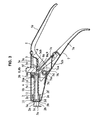
- Fig. 1 is an explanatory side view illustrating an example of a pushing
device 1 for a tooth restoration material mixed and kneaded in a capsule according the present invention. - Fig. 2 is an explanatory plan view of Fig. 1.
- Fig. 3 is an enlarged explanatory side sectional view of Fig. 1.
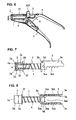
- Fig. 4 is an explanatory side sectional view illustrating the state that a piston rod is frontwardly moved in the pushing device for a tooth restoration material mixed and kneaded in a capsule according to the present invention of Fig. 3.
- Fig. 5 is an explanatory side sectional view illustrating the state that a capsule for a tooth restoration material is mounted on the pushing device for a tooth restoration material mixed and kneaded in a capsule according to the present invention of Fig. 3, and the tooth restoration material is pushed out.
- Fig. 6 is an explanatory side sectional view illustrating another example of a pushing device for a tooth restoration material mixed and kneaded in a capsule according the present invention.
- Fig. 7 is an explanatory partial side sectional view illustrating the state that a piston rod, a leak preventive cover, a ratchet body and a compression coil spring, which are used in the present invention, are assembled.
- Fig. 8 is an explanatory view of a bottom face of Fig. 7.
- Hereinafter, a pushing device for a tooth restoration material mixed and kneaded in a capsule according to the present invention is described concretely with drawings.
- Fig. 1 is an explanatory side view illustrating an example of a pushing
device 1 for a tooth restoration material mixed and kneaded in a capsule according the present invention. Fig. 2 is an explanatory plan view of Fig. 1. Fig. 3 is an enlarged explanatory side sectional view of Fig. 1. Fig. 4 is an explanatory side sectional view illustrating the state that a piston rod is frontwardly moved in the pushing device for a tooth restoration material mixed and kneaded in a capsule according to the present invention of Fig. 3. Fig. 5 is an explanatory side sectional view illustrating the state that a capsule for a tooth restoration material is mounted on the pushing device for a tooth restoration material mixed and kneaded in a capsule according to the present invention of Fig. 3, and the tooth restoration material is pushed out. Fig. 6 is an explanatory side sectional view illustrating another example of a pushing device for a tooth restoration material mixed and kneaded in a capsule according the present invention. Fig. 7 is an explanatory partial side sectional view illustrating the state that a piston rod, a leak preventive cover, a ratchet body and a compression coil spring, which are used in the present invention, are assembled. Fig. 8 is an explanatory view of a bottom face of Fig. 7. - In the drawings, a
cylindrical piston rod 1 is for pushing out a tooth restoration material housed in a capsule C for a tooth restoration material, and thepiston rod 1 has a head part 1a, which at least has a part having a larger outer diameter than that of the backward side at the front end side thereof; a throughhole 1b along the whole length of the piston rod (1); at least more than one slit 1c at a front end thereof; and locking through holes 1d, 1d provided in a side part at the rear end side thereof, where the locking through holes 1d, 1d have a smaller diameter than that of the throughhole 1b, reach to the throughhole 1b, and are opposed each other. Thepiston rod 1 is inserted into a leakpreventive cover 2 from the rear end side thereof, and is fixed to aratchet body 3 in the state that acompression coil spring 4 is provided along an outer periphery of thepiston rod 1. A front end of thepiston rod 1 presses the capsule C for a tooth restoration material mounted on ahousing body 5 so as to push out the mixed and kneaded tooth restoration material housed in the capsule C for a tooth restoration material. Further, thepiston rod 1 guides powder component or the like, which is jetted from a rear end part of the capsule C for a tooth restoration material, into thehousing body 5. - The
piston rod 1 has the head part 1a, which at least has the part having a larger diameter than that of the backward side, at the front end side thereof, as illustrated in Figs 3 to 7. At an initial position, the head part 1a of thepiston rod 1 is housed in a housing part 2b of a leakpreventive cover 2, as illustrated in Figs. 3 and 6. When aratchet body 3, to which thepiston rod 1 is fixed, is frontwardly moved, the head part 1a is frontwardly moved so as to press the capsule C for a tooth restoration material, as illustrated in Fig. 5. When theratchet body 3 is returned to the backward initial position by pressing of a release body 8, the head part 1a is re-housed in the housing part 2b, and backwardly presses an inner wall of the housing part 2b so as to move the leakpreventive cover 2 to the initial position. - Further, the
piston rod 1 has the throughhole 1b along the whole length thereof, and has at least more than one slit 1c at the front end thereof, as illustrated in Figs 3 to 7. When the front end of thepiston rod 1 presses the capsule C for a tooth restoration material, the powder component or the like jetted from the rear end part of the capsule C for a tooth restoration material enters into the throughhole 1b from theslit 1c and an opening of the throughhole 1b, and reach into thehousing body 5. - Further, the
piston rod 1 has the locking through holes 1d, 1d in the side part at the rear end side thereof, where the holes 1d, 1d have a smaller diameter than that of the throughhole 1b, reach to the throughhole 1b and are opposed each other, as illustrated in Figs. 3 to 5. The locking through holes 1d, 1d are for fixing thepiston rod 1 to theratchet body 3, where thepiston rod 1 is fixed by inserting a pistonrod fixing pin 3d of theratchet body 3 from one of holes 3ca for a piston rod fixing pin of theratchet body 3, penetrating the holes 1d, 1d, and reaching to the other of holes 3ca for a piston rod fixing pin. - A leak
preventive cover 2 has a frontend opening part 2a contacted with the rear end part of the capsule C for a tooth restoration material to be mounted; a housing part 2b for housing the head part 1a of thepiston rod 1; an insertinghole 2c for slidably inserting a portion at the backward side from the head part 1a of thepiston rod 1 at the backward side of the housing part 2b in the axial direction; asmall diameter portion 2d provided at the front end side on the outer periphery thereof ; and alarge diameter portion 2e provided at the rear end side on the outer periphery thereof. Thereby, even if the residual powder component or the like being not mixed and kneaded in the capsule body of the capsule C for a tooth restoration material is jetted from the rear end part of the capsule C for a tooth restoration material, the leakpreventive cover 2 prevents the jetted powder component from outwardly scattering, so that the jetted component is not poured on a face of a patient or a dentist, and a patient or a dentist does not inhale the component by mistake. - The leak
preventive cover 2 has the frontend opening part 2a contacted with the rear end part of the capsule C for a tooth restoration material to be mounted, and the housing part 2b for housing the head part 1a of thepiston rod 1, as illustrated in Figs. 3 to 7. The head part 1a of thepiston rod 1 is housed in the housing part 2b of the leakpreventive cover 2 so as not to interfere at the time of mounting the capsule C for tooth restoration material on a mountingpart 5a of ahousing body 5 in the state that thepiston rod 1 is positioned at the initial position. - The housing part 2b of the leak
preventive cover 2 can have any shapes if it can house at least the head part 1a of thepiston rod 1. However, if the housing part 2b has a shape having a diameter which is gradually made larger toward the front end thereof as illustrated in Figs. 3 to 7, the powder component or the like jetted from the rear end part of the capsule C for a tooth restoration material easily flows into the throughhole 1b of thepiston rod 1, so that it is preferable. Further, the powder component or the like is not adhered on the inner face of the housing part 2b, so that it is preferable. - Further, the leak
preventive cover 2 has thesmall diameter portion 2d at the front end side and thelarge diameter portion 2e at the rear end side, on the outer periphery thereof, as illustrated in Figs. 7 and 8. In the leakpreventive cover 2, thesmall diameter portion 2d at the front end side is supported in the state of being slidably inserted into a supportingpath 5b of thehousing body 5, as illustrated in Figs. 3 and 6. Further, when the leakpreventive cover 2 is frontwardly moved, as illustrated in Figs. 4 and 5, a front end of thelarge diameter portion 2e at the rear end side is contacted with a front end in a guidingpath 5c of thehousing body 5. Thereby, the whole leakpreventive cover 2 is controlled so as not to be frontwardly jumped out from the supportingpath 5b of thehousing body 5. - Further, as illustrated in Figs 3 to 5, the leak
preventive cover 2 has aflange part 2f on a rear end outer periphery thereof, and acompression coil spring 11 for a leak preventive cover, which has a smaller spring constant than that of acompression coil spring 4 described below. Thecoil spring 11 is provided along the outer periphery of the leakpreventive cover 2 between theflange part 2f and the front end in the guidingpath 5c of thehousing body 5. Thus, the leakpreventive cover 2 itself can receive backwardly moving force, based on the front end side in the guidingpath 5c of thehousing body 5, and this backwardly moving force for the leakpreventive cover 2 can backwardly move theratchet body 3 itself, to which thepiston rod 1 is fixed, based on a rear face of the leakpreventive cover 2. Therefore, operativitywhen returning thepiston rod 1 and the leakpreventive cover 2 to the backward initial position can be remarkably improved, so that it is preferable. Further, even if the powder component or the like is adhered on the outer periphery of thepiston rod 1 and the outer periphery of the leakpreventive cover 2, thepiston rod 1 and the leakpreventive cover 2 can be certainly returned to the initial position, so that it is preferable. - The reason why the spring constant of the
compression coil spring 11 for a leak preventive cover is necessarily to be smaller than that of thecompression coil spring 4 in this embodiment is as follows. If the spring constant of thecompression coil spring 11 for a leak preventive cover is larger than thecompression coil spring 4, when theratchet body 3 is frontwardly moved, thecompression coil spring 4 is compressed before thecompression coil spring 11 for a leak preventive cover is compressed, so that only thepiston rod 1 is frontwardly moved. In such a case, thepiston rod 1 presses the capsule C for a tooth restoration material in the state that the leakpreventive cover 2 is not contacted with the rear end part of the capsule C for a tooth restoration material, and as a result of this, the residual powder component or the like, which is not mixed and kneaded in the capsule body of the capsule C for a tooth restoration material, is jetted outwardly from the rear end part of the capsule C for a tooth restoration material. - A
ratchet body 3 has, from the frontward side to the backward side at a center part in the width direction, anupward wall part 3a having a release body inserting part 3aa; afrontward wall part 3b having a piston rod inserting hole 3ba provided for inserting the rear end part of thepiston rod 1; and bothside wall parts piston rod 1 inserted into the piston rod inserting hole 3ba is fixed with theratchet body 3 by a pistonrod fixing pin 3d inserted into the both locking through holes 1d, 1d and the both holes 3ca, 3ca for a piston rod fixing pin. Theratchet body 3 is frontwardly moved by a pressing pawl 7ca of apressing body 7c of alever 7 while resisting against acompression coil spring 4, so as to frontwardly move thepiston rod 1 and the leakpreventive cover 2. - The
ratchet body 3 includes theupward wall part 3a, thefrontward wall part 3b, and the bothside wall parts upward wall part 3a has the release body inserting part 3aa from the frontward side to the backward side at the center part in the width direction. The release body inserting part 3aa is inserted with a button part 8b of a release body 8, as illustrated in Figs. 3 to 6. - The
frontward wall part 3b of theratchet body 3 has the piston rod inserting hole 3ba provided for inserting the rear end part of thepiston rod 1, and the bothside wall parts ratchet body 3 respectively have the holes 3ca for a piston rod fixing pin provided through at the frontward side thereof. When thepiston rod 1 is fixed to theratchet body 3, thepiston rod 1 is inserted into the frontend opening part 2a of the leakpreventive cover 2 from the rear end side thereof, and acompression coil spring 4 is provided along the outer periphery of thepiston rod 1 projected from the rear end side of the leakpreventive cover 2. Then, the rear end of thepiston rod 1 is inserted into the piston rod inserting hole 3ba of thefrontward wall part 3b of theratchet body 3, so as to arrange the locking through holes 1d, 1d and the holes 3ca for a piston rod fixing pin, 3ca of the bothside wall parts ratchet body 3 approximately in line when seeing from theside wall part 3c side. After that, the pistonrod fixing pin 3d is inserted from any one of the holes 3ca, 3ca for a piston rod fixing pin into the both locking through holes 1d, 1d and the both holes 3ca, 3ca for a piston rod fixing pin. Thereby, thepiston rod 1 is fixed at theratchet body 3 as illustrated in Figs. 7 and 8. - Further, the both
side wall parts ratchet body 3 have a rack part 3cb for a ratchet formed at a lower edge at the rear side of the holes 3ca for a piston rod fixing pin, as illustrated in Figs. 7 and 8. The rack part 3cb for a ratchet is constantly given the force for upwardly pressing by a lockingpawl 6a of a ratchet body lockingplate spring 6, which is inserted into a root part of the cogs of the rack part 3cb, so as to prevent move of theratchet body 3 itself in the front and rear directions. Further, the rack part 3cb for a ratchet is frontwardly pressed by the force larger than the force upwardly pressing by the a lockingpawl 6a of the ratchet body lockingplate spring 6, so as to move frontwardly theratchet body 3 itself. The frontwadly pressing force is given by a pressing pawl 7ca of apressing body 7c of alever 7 which is inserted into a root part of the cogs of theratchet body 3 and positioned at the frontward side from the root part of the cogs of theratchet body 3, in which the locking pawl 6c of the ratchet body lockingplate spring 6 is inserted. - As for the rack part 3cb for a ratchet of the both
side wall parts 3c of theratchet body 3, it is not limited especially if it has a rack shape having a plurality of the cogs capable of preventing move of theratchet body 3 itself in front and rear directions by the ratchet body lockingplate spring 6 as described above, and capable of frontwardly moving theratchet body 3 itself by alever 7. However, if the tooth of the rack part 3cb for a ratchet has a shape in which the length of a front side of the root part is shorter than the length of a back side as illustrated in Figs. 3 to 8, theratchet body 3 can be frontwardly moved smoothly, so that it is preferable. - Further, a flat part not having the cogs is formed at the backward side of the rack part 3cb for a ratchet as illustrated in Figs. 3 to 8. When the root part of the cogs is frontwardly pressed by the pressing pawl 7ca in the state that a pressing pawl 7ca of a
pressing body 7c of alever 7 is inserted into a root part of the cogs at the most backward side of the rack part 3cb for a ratchet, that is, the state just before the tooth restoration material mixed and kneaded in the capsule body of the capsule C for a tooth restoration material is finally pushed out by thepiston rod 1, a lockingpawl 6a of a ratchet body lockingplate spring 6 is contacted with the flat part not having the cogs formed at the backward side of the rack part 3cb for a ratchet so as not enable to prevent move of the ratchet body in the front and rear direction. So, theratchet body 3 can be freely moved in the front and rear directions by rotating alever body 7a of thelever 7 by small force. Thereby, by adjusting the pressing force given to the capsule C for a tooth restoration material by thepiston rod 1, the amount of the tooth restoration material pushed out from the inside of the capsule C for a tooth restoration material can be freely adjusted, so that it is preferable. - The tooth restoration material mixed and kneaded in the capsule generally needs a large space for mixing and kneading, so that the amount of the material is little to a size of the capsule, and has remarkably high viscosity. So, in the case of the general capsule C for a tooth restoration material, only after the pressing part of the plunger or the like in the capsule C for a tooth restoration material is frontwardly slid to a position near the front end thereof, the tooth restoration material in the capsule C for a tooth restoration material is pushed out. Thus, in the mode that the part not having a tooth is formed at the backward side of the rack part 3cb for a ratchet as described above, the constitution is made such that the pressing part of the plunger or the like in the capsule C for a tooth restoration material is moved by the
piston rod 1 to a position near the front end, that is, a position just before the tooth restoration material in the capsule C for a tooth restoration material is finally pushed out, in the state that the pressing pawl 7ca of thepressing body 7c of thelever 7 is inserted into the root part of the cogs at the most backward side of the rack part 3cb for a ratchet. Thereby, the amount of the tooth restoration material pushed out from the inside of the capsule C for a tooth restoration material can be freely controlled by operating thelever body 7a of thelever 7 described below. - Further, the
upward wall part 3a and the bothside wall parts ratchet body 3 are formed with a smooth member made of a synthetic resin, although it is not illustrated in the drawings, or a smooth slidingmember 3e made of a synthetic resin, which is contacted with the inner face of the guidingpath 5c of thehousing body 5, is adhered on the upper face of theupward wall part 3a and/or side faces of the bothside wall parts ratchet body 3 as illustrated in Figs. 3 to 5. In such the constitution, when theratchet body 3 is moved in the front and rear directions, frictional force generated between theratchet body 3 and the guidingpath 5c of the housing body5 can be decreased, so that it is preferable. In addition to this, an operation of the whole device of the present invention can be smoothed, so that it is preferable. Especially, in the constitution that the smooth slidingmember 3e made of a synthetic resin, which is contacted with the inner face of the guidingpath 5c of thehousing body 5, is adhered on the upper face of theupward wall part 3a and/or side faces of the bothside wall parts ratchet body 3, when theupward wall part 3a or the bothside wall parts ratchet body 3 are made of metal, the operation of the whole device of the present invention can be smoothed without decreasing rigidity of theratchet body 3 itself, so that it is preferable. Further, as the synthetic resin, a material such as a silicon based material, a fluorine compound, a polyoxymethylene resin (POM) or the like can be desirably used. - A
compression coil spring 4 is provided between the rear face of the leakpreventive cover 2 and the front face of thefrontward wall part 3b of theratchet body 3, and is provided along the outer periphery of thepiston rod 1. Thecompression coil spring 4 constantly give force for frontwardly pressing the leakpreventive cover 2 so as to contact the frontend opening part 2a of the leakpreventive cover 2 to the rear end part of the capsule C for a tooth restoration material mounted on a mountingpart 5a at a front end of ahousing body 5 described below. Further, thecompression coil spring 4 constantly gives force for backwardly pressing theratchet body 3 so as to return theratchet body 3 to the initial position when the locking state of a ratchet body lockingplate spring 6 and alever 7 to theratchet body 3 is canceled by pressing a release body 8 described below. - The
compression coil spring 4 is provided along the outer periphery of thepiston rod 1, between the rear face of thepreventive cover 2 and the front face of thefrontward wall part 3b of theratchet body 3, as illustrated in Figs. 7 and 8. Thecompression coil spring 4 is for keeping the state that the head part 1a of thepiston rod 1 is contacted with the housing part 2b of the leakpreventive cover 2. Theratchet body 3 is frontwardly moved so as to contact the frontend opening part 2a of the leakpreventive cover 2 to the rear endpart of the capsule C for a tooth restoration material, and/or to contact the front end of thelarge diameter portion 2e of the leakpreventive cover 2 to the front end in the guidingpath 5c of thehousing body 5, and after that, the ratchet body is frontwardly moved more. Thereby, the distance between the rear face of the leakpreventive cover 2 and the front face of thefrontward wall part 3b of theratchet body 3 is shortened and thecompression coil spring 4 is compressed, as the head part 1a of thepiston rod 1 projects to more frontward position beyond the frontend opening part 2a of the leakpreventive cover 2 from the state of contacting to the housing part 2b of the leakpreventive cover 2. Thereby, the locking state of the ratchet body lockingplate spring 6 and thelever 7 to theratchet body 3 is canceled. At this time, thecompression coil spring 4 generates pressing force for returning theratchet body 3 to the initial position. - Further, in addition to the
compression coil spring 4, an auxiliarycompression coil spring 10 can be provided between the front end side of the guidingpath 5c of thehousing body 5 and thefrontward wall part 3b of theratchet body 3, and along the outer peripheries of the leakpreventive cover 2 and thecompression coil spring 4, as illustrated in Fig. 6. Further, acompression coil spring 11 for a leak preventive cover having a smaller spring constant than that of thecompression coil spring 4 can be provided between theflange part 2f, which is formed on the rear end outer periphery of the leakpreventive cover 2, and the front end of the guidingpath 5c of thehousing body 5, and along the outer periphery of the leakpreventive cover 2, as illustrated in Figs. 3 to 5. In such the constitution, when a button part 8b of a release body 8 is downwardly pressed so as to return thepiston rod 1 and the leakpreventive cover 2 to the backward initial position, the auxiliarycompression coil spring 10 gives force for backwardly moving theratchet body 3 itself, to which thepiston rod 1 inserted in the leakpreventive cover 2 is fixed, based on the front end side in the guidingpath 5c of thehousing body 5. Further, thecompression coil spring 11 for a leak preventive cover gives force for backwardly moving the leakpreventive cover 2 itself, based on the front end side in the guidingpath 5c of thehousing body 5, and gives force for backwardly moving the leakpreventive cover 2 backwardly moves theratchet body 3 itself , to which thepiston rod 1 is fixed, based on the rear face of the leakpreventive cover 2. Therefore, operativity when returning thepiston rod 1 and the leakpreventive cover 2 to the backward initial position can be remarkably increased, so that, it is preferable. Further, even if the powder component or the like is adhered on the outer peripheries of thepiston rod 1 and the leakpreventive cover 2, thepiston rod 1 and the leakpreventive cover 2 can be certainly returned to the backward initial position, so that it is preferable. - A
housing body 5 has a mountingpart 5a on which the capsule C for a tooth restoration material is mounted; a supportingpath 5b in which thesmall diameter portion 2d of the leakpreventive cover 2 is slidably inserted; a guidingpath 5c in which thepiston rod 1, thecompression coil spring 4 and theratchet body 3 are provided movably in the front and rear directions in the state of contacting to theupward wall part 3a of theratchet body 3; a throughhole 5d for a lever shaft provided at the both side wall parts below the guidingpath 5c; agrip part 5e provided at the rear end side; and anopening part 5f for a release body at a position of an upper side of the guidingpath 5c, where this position is at least connected with the release body inserting part 3aa of theratchet body 3 when theratchet body 3 is moved at the most backward side so as to be positioned at the initial position. In thehousing body 5, the mountingpart 5a, the supportingpath 5b and the guidingpath 5c are provided in this order from a front end toward the rear at an upper part thereof. Thehousing body 5 is mounted with the capsule C for a tooth restoration material, and is for supporting each member. - The
housing body 5 has the mountingpart 5a at the front end of the upper part thereof for mounting the capsule C for a tooth restoration material. For example, the mountingpart 5a can have a shape so as to hold the rear end part of the capsule C for a tooth restoration material, or a shape so as to only put the rear end part of the capsule C for a tooth restoration material, although the shape is not illustrated in the drawings. Further, the mountingpart 5a can have an engaging part projecting from the front end side of the supportingpath 5b, so as to engage to a groove part formed on the outer periphery of the rear end part of the capsule C for a tooth restoration material, as illustrated in Figs 1 to 5. - At the rear side of the mounting
part 5a at the front end of thehousing body 5, as illustrated in Figs. 3 to 6, the supportingpath 5b and the guidingpath 5c are provided in this order. In the supportingpath 5b, thesmall diameter portion 2d of the leakpreventive cover 2 is slidably inserted. The guidingpath 5c has thepiston rod 1, thecompression coil spring 4 and theratchet body 3 which are provided movably in the front and rear directions while contacting to theupward wall part 3a of theratchet body 3. Thepiston rod 1, the leakpreventive cover 2, theratchet body 3 and thecompression coil spring 4 are integrally assembled as illustrated in Figs. 7 and 8. These assembled parts are provided movably in the front and rear directions in the guidingpath 5c, as illustrated in Figs. 3 to 6, in the state that thesmall diameter portion 2d of the leakpreventive cover 2 is slidably supported by the supportingpath 5b, and in the state that root parts of teeth of the rack parts 3cb, 3cb for a ratchet of the bothside wall parts ratchet body 3 are upwardly pressed by a lockingpawl 6a of a ratchet body lockingplate spring 6 and a pressing pawl 7ca of apressing body 7c of alever 7. - The guiding
path 5c of thehousing body 5 has the throughholes 5d for a lever shaft on the both side walls at the lower part thereof, and has thegrip part 5e on the rear end side thereof as illustrated in Figs 1 to 6. The throughholes 5d for a lever shaft are for rotatably mounting alever body 7a of alever 7 by a lever shaft 7aa, and thegrip part 5e is used when operating thelever body 7a of thelever 7. More particularly, thelever body 7a of thelever 7 is operated by upwardly moving it using the inner sides of fingers while contacting the upper part of thegrip part 5e with a palm. - Further, the
housing body 5 has theopening part 5f for a release body at the position at the upper part of the guidingpath 5c, where the position is at least connected with the release body inserting part 3aa of theratchet body 3 when theratchet body 3 is moved to the most backward side so as to be positioned at the initial position. Theopening part 5f for a release body is for inserting a button part 8b of a release body 8, which is provided between the bothside wall parts ratchet body 3 in the guidingpath 5b of thehousing body 5, as illustrated in Figs. 3 to 6. - A ratchet body locking
plate spring 6 has a lockingpawl 6a, is for constantly giving force for upwardly pressing theratchet body 3 so as to prevent move of theratchet body 3 in the front and rear directions. A rear end of the lockingpawl 6a is fixed at the backward side from the guidingpath 5c in thehousing body 5, and a front end of the lockingpawl 6a is inserted into a root part of the cogs of the rack part 3cb for a ratchet of theratchet body 3. Theplate spring 6 is for supporting thepiston rod 1, the leakpreventive cover 2, theratchet body 3 and thecompression coil spring 4, which are provided in the guidingpath 5c of thehousing body 5 and are integrally assembled as illustrated in Figs. 7 and 8. Further, theplate spring 6 is for supporting a release body 8, which is provided between the bothside wall parts ratchet body 3. Furthermore, theplate spring 6 is for locking theratchet body 3 while resisting against the pressing force by thecompression coil spring 4, so that theratchet body 3 frontwardly moved by alever 7 can keep the position after being moved. - When the
lever 7 is not operated, the lockingpawl 6a at the front end of the ratchet body lockingplate spring 6 is inserted into the root part of the cogs of the rack part 3cb for a ratchet of theratchet body 3 as illustrated in Figs. 3 and 6, and the ratchet body lockingplate spring 6 constantly gives the force for upwardly pressing theratchet body 3, so as to prevent move of theratchet body 3 in the front and rear directions. When thelever 7 is operated so as to frontwardly move theratchet body 3, the lockingpawl 6a inserted into the root part of the cogs of the rack part 3cb for a ratchet of theratchet body 3 is pressed gradually and downwardly by a crest part of the cogs of the rack part 3cb for a ratchet according to frontwardly moving of the rack part 3cb for a ratchet. Further, when the lockingpawl 6a passes a top point of the cogs of the rack part 3cb for a ratchet by further frontwardly moving of the rack part 3cb for a ratchet, the lockingpawl 6a is inserted into a root part of the cogs which is just behind the above-described cogs, so as to be again in a state of preventing move of theratchet body 3 in the front and rear directions. - A
lever 7 has alever body 7a rotatably mounted on a lever shaft 7aa fixed at the throughhole 5d for a lever shaft of thehousing body 5; atorsion spring 7b being provided along the outer periphery of the lever shaft 7aa and constantly giving force for downwardly rotating the backward side from the lever shaft 7aa of thelever body 7a; and apressing body 7c having one end part axially supported at the backward side from the lever shaft 7aa of thelever body 7a, and constantly giving force for inserting a pressing pawl 7ca formed at another end thereof into the root part of the cogs of the rack part 3cb for a ratchet of theratchet body 3, which is positioned at the frontward side from the lockingpawl 6a of the ratchet body lockingplate spring 6. This force is given by a spring 7cb for a pressing body provided between thepressing body 7c and thelever body 7a. In thelever 7, when a portion at the backward side from the lever shaft 7aa of thelever body 7a is upwardly rotated, the pressing pawl 7ca of thepressing body 7c frontwardly presses the root part of the cogs of the rack part 3cb for a ratchet of theratchet body 3 so as to frontwardly move the tooth of the rack part 3cb for a ratchet body to the just frontward position by one cog. At this time, the force for upwardly rotating is given while resisting against the rotating force given by thetorsion spring 7b and the pressing force by thecompression coil spring 4 and the ratchet body lockingplate spring 6. When the force for upwardly rotating is canceled, the pressing pawl 7ca of thepressing body 7c is inserted into a root part of the cogs, which is just behind the cog of the rack part 3cb for a ratchet moved by the pressing pawl 7ca of thepressing body 7c, so as to return thelever body 7a to the initial position. Thelever 7 is for frontwardly moving the leakpreventive cover 2 so as to contact the frontend opening part 2a of the leakpreventive cover 2 with the rear end part of the capsule C for a tooth restoration material mounted on the mountingpart 5a of thehousing body 5, and is for frontwardly moving thepiston rod 1 so as to press the rear end part of the capsule C for a tooth restoration material. - The
lever body 7a of thelever 7 is rotatably mounted on the lever shaft 7aa fixed at the throughhole 5d for a lever shaft of thehousing body 5, and is constantly given the force for downwardly rotating the backward side from the lever shaft 7aa of thelever body 7a by thetorsion spring 7b provided along the outer periphery of the lever shaft 7aa, as illustrated in Figs 1 to 6. When thelever 7 is operated so as to frontwardly move theratchet body 3, thelever body 7a is upwardly rotated while resisting against thecompression coil spring 4 and the ratchet body lockingplate spring 6. Further, if the auxiliarycompression coil spring 10 and thecompression coil spring 11 for a leak preventive cover are provided, thelever body 7a is upwardly rotated while against these coil springs. - Further, the one end part of the
pressing body 7c is axially supported at the backward side from the lever shaft 7aa of thelever body 7a of thelever 7. Thepressing body 7c is constantly given the force for inserting the pressing pawl 7ca into the root part of the cogs of the rack part 3cb for ratchet of theratchet body 3 at the frontward side from the lockingpawl 6a of the ratchet body lockingplate spring 6, where the pressing pawl 7ca is formed at the other end of thepressing body 7c. This force for inserting the pressing pawl 7ca is given by the spring 7cb for a pressing body provided between thepressing body 7c and thelever body 7a, as illustrated in Figs. 3 to 6. Thepressing body 7c supports a release body 8 using the pressing force given by the spring 7cb for a pressing body together with theratchet body 3, where the release body 8 is provided between the bothside wall parts ratchet body 3. Further, when the portion at the backward side from the lever shaft 7aa of thelever body 7a is upwardly rotated, the pressing pawl 7ca frontwardly presses the root part of the cogs of the rack part 3cb for a ratchet of theratchet body 3 so as to move the cogs the rack part 3cb for a ratchet to a just frontward position by one cog, as described above. - Further, the
pressing body 7c constantly receives the force for being inserted into the root part of the cogs of the rack part 3cb for a ratchet of theratchet body 3 by the spring 7cb for a pressing body. So, when the force for upwardly rotating the portion at the backward side from the lever shaft 7aa of thelever body 7a is canceled, theratchet body 3 frontwardly moved is prevented to be moved in the front and rear directions by the ratchet body lockingplate spring 6. Further, when the portion at the backward side from the lever shaft 7aa of thelever body 7a is returned to the initial position by thetorsion spring 7b, the pressing pawl 7ca is pressed downwardly and gradually by the crest part of the cogs of the rack part 3cb for a ratchet while resisting against the spring 7cb for a pressing body, according to downwardly moving of the portion at the backward side from the lever shaft 7aa of thelever body 7a. Further, when the pressing pawl 7ca is downwardly rotated more so as to pass the top point of the cogs of the rack part 3cb for a ratchet, the pawl 7ca is inserted into a root part of the cogs just behind the above-described tooth by one cog, so as to be in the state that it can be moved again toward the front of theratchet body 3. - Further, the spring 7cb for a pressing body of the
pressing body 7c of thelever 7 is a compression coil spring provided between thepressing body 7c and thelever body 7a, which is not illustrated in the drawings, or a plate spring provided between thepressing body 7c and thelever body 7a as illustrated in Figs. 3 to 6. Thereby, the spring 7cb for a pressing body can be suitably selected corresponding to the shapes of thehousing body 5, thelever 7 and the like, so that it is preferable. - A release body 8 has a pressing part 8a provided between both
sides wall parts ratchet body 3, and a button part 8b which is continuously formed above the pressing part 8a, has a smaller area of a transverse section than that of a transverse section rectangular to the moving direction of the pressing part 8a, and is projected from theopening part 5f for a release body of thehousing body 5. In the release body 8, when the button part 8b is downwardly pressed, the pressing part 8a downwardly moves the lockingpawl 6a of the ratchet body lockingplate spring 6 and the pressing pawl 7ca of thepressing body 7c of thelever 7, which are inserted into the root part of the cogs of the rack part 3cb for a ratchet of theratchet body 3, so as to cancel the locking state with the rack part 3cb for a ratchet. The release body 8 is for backwardly moving theratchet body 3 so as to return thepiston rod 1 and the leakpreventive cover 2 to the initial position. - The release body 8 is provided between the both
side wall parts ratchet body 3, in the state that the button part 8b is projected from theopening part 5f for a release body of thehousing body 5, and in the state that the lower end of the pressing part 8a is positioned above the lockingpawl 6a of the ratchet body lockingplate spring 6 and the pressing pawl 7ca of thepressing body 7c of thelever 7. The lockingpawl 6a and thepressing pawl 7a are inserted into the root part of the cogs of the rack part 3cb for a ratchet of theratchet body 3, as illustrated in Figs. 1 to 6. Further, when the button part 8b of the release body 8 is downwardly pressed, the pressing part 8a of the release body 8 is downwardly moved. According to backwardly moving of the pressing part 8a, the lockingpawl 6a of the ratchet body lockingplate spring 6 and the pressing pawl 7ca of thepressing body 7c of thelever 7, which are inserted into the root part of the cogs of the rack part for a ratchet 3cb of theratchet body 3, are downwardly moved so as to cancel the locking state with the rack part 3cb for a ratchet. Therefore, theratchet body 3 is backwardly pressed and returned to the initial position by the pressing force of thecompression coil spring 4, which is compressed by contracting of the distance between the rear face of the leakpreventive cover 2 and the front face of thefrontward wall part 3b of theratchet body 3. When the auxiliarycompression coil spring 10 and thecompression coil spring 11 for a leak preventive cover are provided, theratchet body 3 is also pressed and returned to the initial position by these pressing forces. - Further, the reason that the button part 8b of the release body 8 is formed to have the smaller area of the transverse section than the area of transverse section rectangular to the moving direction of the pressing part 8a which is continuously formed below the button part 8b is as follows. If the area of the transverse section rectangular to the moving direction of the button part 8b is larger than the transverse section rectangular to the moving direction of the pressing part 8a, the pressing part 8a may enter into the
opening part 5f for a release body of thehousing body 5, or the pressing part 8a may be removed from theopening part 5f for a release body of thehousing body 5, so that the release body 8 itself may be removed from the guidingpath 5c of thehousing body 5. - A stopper means 9 is for controlling to stop the
ratchet body 3, which is backwardly moved by the pressing force of thecompression coil spring 4, at the initial position when the locking state of the lockingpawl 6a of the ratchet body lockingplate spring 6 and the pressing pawl 7ca of thepressing body 7c of thelever 7 to the rack part 3cb for a ratchet is canceled by the release body 8. The stopper means 9 prevents run over of thepiston rod 1, the leakpreventive cover 2, ratchetbody 3 and thecompression coil spring 4 from the inside of the guidingpath 5c of thehousing body 5, when theratchet body 3 is backwardly moved by the excess pressing force of thecompression coil spring 4 so as to be moved behind initial position. Further, the stopper means 9 prevents removal of thesmall diameter portion 2d at the front end side of the leakpreventive cover 2 from the supportingpath 5b of thehousing body 5. - As for the stopper means 9, for example, another projection for controlling to stop the
ratchet body 3 at the initial position can be separately provided at the rear end of the guidingpath 5c of thehousing body 5, although the projection is not illustrated in the drawings. However, it is preferable, if a stopper means for controlling to stop theratchet body 3 at the initial position can be formed by contacting the front end of a release body inserting part at theupward wall part 3a of theratchet body 3, which is backwardly moved, to the button part 8b of the release body 8 and/or by contacting the rear end of thepiston rod 1 fixed at theratchet body 3, which is backwardly moved, to the pressing part 8a of the release body 8, as illustrated in Figs. 3 to 6, because the stopper means can be made by only changing the shapes of the button part 8b of the release body 8 and the release body inserting part 3aa of theupward wall part 3a of theratchet body 3, and the shape of the pressing part 8a. - Then, a method of using the pushing device of a tooth restoration material mixed and kneaded in a capsule according to the present invention having the above-described constitution is described.
- When the
ratchet body 3 is positioned at the front side from the initial position as illustrated in Fig. 4, that is, when thepiston rod 1 and the leakpreventive cover 2 are projected from the supportingpath 5b of thehousing body 5, an operation for returning theratchet body 3 to the initial position is carried out as a preparation at first. - This operation is carried out by downwardly pressing the button part 8b of the release body 8. More particularly, when the button part 8b of the release body 8 is downwardly pressed, the locking
pawl 6a of the ratchet body lockingplate spring 6 and the pressing pawl 7ca of thepressing body 7c of thelever 7 are downwardly moved by the pressing part 8a of the release body 8, so as to cancel the locking state with the rack part 3cb for a ratchet, where these pawls are inserted into the root part of the cogs of the rack part 3cb for a ratchet of theratchet body 3 before this operation. Further, theratchet body 3 is backwardly pressed and moved to the initial position by the pressing force of thecompression coil spring 4, which is compressed by contracting of the distance between the rear face of the leakpreventive cover 2 and the front face of thefrontward wall part 3b of theratchet body 3 and theratchet body 3 is also backwardly moved by the pressing forces of the auxiliarycompression coil spring 10 and thecompression coil spring 11 for a leak preventive cover when these are provided. Then, the backwardly movedratchet body 3 is controlled so as to be stopped at the initial position by the stopper means 9. - Then, in the state that the
ratchet body 3 is positioned at the initial position as illustrated in Figs. 3 and 6, an operation for mounting the capsule C for a tooth restoration material on the mountingpart 5a at the front end of thehousing body 5 is carried out, where the powder component and the liquid component constituting a tooth restoration material such as a dental cement isolatedly housed in the capsule C in the predetermined amounts are mixed and kneaded by an automatic kneading device or the like. - For example, when the mounting
part 5a of thehousing body 5 has an engaging part which is formed projecting from the front end side of the supportingpath 5b so as to engage to a groove part formed on the outer periphery of the rear end part of the capsule C for a tooth restoration material as illustrated in Figs. 1 to 6, this operation is carried out by engaging the groove part of the rear end part of the capsule C for a tooth restoration material to the engaging part of the mountingpart 5a as illustrated in Fig. 5. - After completing the above-described preparation, the front
end opening part 2a of the leakpreventive cover 2 is contacted to the rear end part of the capsule C for a tooth restoration material mounted on the mountingpart 5a of thehousing body 5. This operation is carried out by upwardly rotating a portion at the backward side from thelever body 7a of thelever 7, while resisting against the rotating force given by thetorsion spring 7b, and against the pressing forces by thecompression coil spring 4 and the ratchet body lockingplate spring 6, and also against the forces by the auxiliarycompression soil spring 10 and thecompression coil spring 11 for a leak preventive cover when these are provided, similarly to the ordinary lever operation for pushing out the tooth restoration material housed in the capsule C for a tooth restoration material. - At this time, when the portion at the backward side from the
lever body 7a of thelever 7 is upwardly rotated, the pressing pawl 7ca formed at another end of thepressing body 7c frontwardly presses the root part of the cogs of the rack part 3cb for a ratchet of theratchet body 3 so as to move the cogs of the rack part 3cb for a ratchet to the just frontward position by one cog, where one end part of thepressing body 7c is axially supported at the backward side from the lever shaft 7aa of thelever body 7a and the pressing pawl 7ca is formed at another end thereof. However, the leakpreventive cover 2, which is inserted with thepiston rod 1 in the state of not frontwardly moving more by the head part 1a of thepiston rod 1 fixed at theratchet body 3, as illustrated in Figs. 7 and 8, is in the state of being pressed constantly and frontwardly by thecompression coil spring 4, which is provided along the outer periphery of thepiston rod 1, between the rear face of the leakpreventive cover 2 and the front face of thefrontward wall part 3b of theratchet body 3. The leakpreventive cover 2 is also in the state that the inner face of the housing part 2b thereof is contacted with the head part 1a of thepiston rod 1. Therefore, when theratchet body 3 is frontwardly moved in these states, the leakpreventive cover 2 frontwardly slides in the supportingpath 5b of thehousing body 5 in the state that the inner face of the housing part 2b of thecover 2 is contacted with the head part 1a of thepiston rod 1, as illustrated in Fig. 4, and finally, the frontend opening part 2a of thecover 2 is contacted with the rear end part of the capsule C for a tooth restoration material. - Further, in the case that the
compression coil spring 11 for a leak preventive cover having smaller spring constant than that of thecompression coil spring 4 is provided along the outer periphery of the leakpreventive cover 2 between theflange part 2f formed on the rear end outer periphery of the leakpreventive cover 2, and the front end in the guidingpath 5c of thehousing body 5 as illustrated in Figs. 3 to 5, when the portion at the backward side from thelever body 7a of thelever 7 is upwardly rotated so as to frontwardly move theratchet body 3, the distance between the front end in the guidingpath 5c of thehousing body 5 and the front face of thefrontward wall part 3b of theratchet body 3 contracts, so that the pressing forces by thecompression coil spring 4 and thecompression coil spring 11 for a leak preventive cover are increased. However, since the spring constant of thecompression coil spring 11 for a leak preventive cover is smaller than that of thecompression coil spring 4, thecompression coil spring 11 for a leak preventive cover is compressed first as it is beaten by the pressing force by thecompression coil spring 4. Thus, after the distance between theflange part 2f and the front end in the guidingpath 5c of thehousing body 5 contracts first, the distance between the rear face of the leakpreventive cover 2 and the front face of thefrontwardwall part 3b of theratchet body 3 contracts. Therefore, the leakpreventive cover 2 frontwardly slides in the supportingpath 5b of thehousing body 5, and finally, the frontend opening part 2a of thecover 2 contacts to the rear end part of the capsule C for a tooth restoration material. - Then, an operation for pushing out a tooth restoration material housed in the capsule C for a tooth restoration material is carried out by upwardly rotating the portion at the backward side from the
lever body 7a of thelever 7 repeatedly so as to frontwardly move thepiston rod 1. - The operation for upwardly rotating the portion at the backward side from the
lever body 7a of thelever 7 is carried out at first while resisting against the rotating force given by thetorsion spring 7b and the pressing forces by thecompression coil spring 4 and the ratchet body lockingplate spring 6, and also against the forces by the auxiliarycompression coil spring 10 and thecompression coil spring 11 for a leak preventive cover if these springs are provided, similarly to the operation for contacting the frontend opening part 2a of the leakpreventive cover 2 with the rear end part of the capsule C for a tooth restoration material mounted on the mountingpart 5a of thehousing body 5. Thereby, the pressing pawl 7ca formed at another end of thepressing body 7c, one end part of which is axially supported at the backward side from the lever shaft 7aa of thelever body 7a, frontwardly presses the root part of the cogs of the rack part 3cb for a ratchet of theratchet body 3 so as to frontwardly move the cogs of the rack part 3cb for a ratchet to the just frontward position by one cog. Then, thepiston rod 1 fixed at theratchet body 3 also moves the cogs of the rack part 3cb for a ratchet to the just frontward position by one cog. - In this case, the locking
pawl 6a of the ratchet body lockingplate spring 6, which is inserted into a root part of the cogs positioned at the backward side from the root part of the cogs of the rack part 3cb for a ratchet of theratchet body 3 inserted with the pressing pawl 7ca, is pressed gradually and downwardly by the crest part of the cogs of the rack part 3cb for a ratchet according to frontwardly moving of the rack part 3cb for a ratchet, and thereby, the rack part 3cb for a ratchet is frontwardly moved more. Then, when the lockingpawl 6a passes the top point of the cogs of the rack part 3cb for a ratchet, the lockingpawl 6a is inserted into the root part of the cogs which is just behind the above-described cogs, so as to be again in the state of preventing move of theratchet body 3 in the front and rear directions. So, thepiston rod 1 fixed at theratchet body 3 also keep the state that the cogs of the rack part 3cb for a ratchet is moved to the just frontward position by one cog. - Then, when the force for upwardly rotating the portion at the backward side from the lever shaft 7aa of the
lever body 7a of thelever 7 is canceled from the above-described state, since theratchet body 3 is prevented to be moved in the front and rear directions by the lockingpawl 6a of the ratchet body lockingplate spring 6 inserted into the root part of the cogs of the rack part 3cb for a ratchet of theratchet body 3, the pressing pawl 7ca of thepressing body 7c, which is constantly given the force for being inserted into the root part of the cogs of the rack part 3cb for a ratchet of theratchet body 3 by the spring 7cb for a pressing body, is downwardly and gradually pressed by the crest part of the cogs of the rack part 3cb for a ratchet while resisting against the spring 7cb for a pressing body according to downwardly rotating of thelever body 7a when it returns to the initial position bytorsion spring 7b. Further, when the pressing pawl 7ca is downwardly rotated more so as to pass the top point of the cogs of the rack part 3cb for a ratchet, the pressing pawl 7ca is inserted into a root part of the cogs which is just behind the above-described cogs by one cog, so as to be in the state that it can be moved again toward the front of theratchet body 3 by one cog. - Then, the operation for upwardly rotating the portion at the backward side from the
lever body 7a of thelever 7, and the operation for canceling the force for upwardly rotating the portion at the backward side from thelever body 7a of thelever 7 are repeated, so as to frontwardly and successively move thepiston rod 1 fixed at theratchet body 3, and thereby, the tooth restoration material housed in the capsule C for a tooth restoration material can be pushed out as illustrated in Fig. 5. - In this case, even if the residual powder component or the like which is not mixed and kneaded in the capsule body of the capsule C for a tooth restoration material is jetted from the rear end part of the capsule C for a tooth restoration material by pressing the capsule C, the front
end opening part 2a of the leakpreventive cover 2 is already contacted with the rear end part of the capsule C for a tooth restoration material as illustrated in Fig. 5. So, the jetted powder component or the like is not jetted to the outside due to the existence of the leakpreventive cover 2, but enters into thehousing body 5 through the throughhole 1b of thepiston rod 1 from theslit 1c and the opening of the throughhole 1b of thepiston rod 1. Therefore, it can be prevented that the powder component or the like is poured on a face of a patient or a dentist, and a patient or a dentist inhales it by mistake. - Finally, after pushing out a desired amount of the tooth restoration material from the capsule C for a tooth restoration material, when the used capsule C for a tooth restoration material mounted on the mounting
part 5a of thehousing body 5 is returned to be detachable state, an operation for backwardly moving theratchet body 3 by downwardly pressing the release body 8 so as to return thepiston rod 1 and the leakpreventive cover 2 to the initial position is carried out. As a result of this operation, the front end part of thepiston rod 1 inserted into the capsule body of the capsule C for a tooth restoration material can be removed from the inside of the capsule body of the capsule C for a tooth restoration material. - In this operation, when the button part 8b of the release body 8 is downwardly pressed, the pressing part 8a continuously formed with the buttonpart 8b is downwardly moved, and thereby, the locking
pawl 6a of the ratchet body lockingplate spring 6 and the pressing pawl 7ca of thepressing body 7c of thelever 7, which are inserted into the root part of the cogs of the rack part 3cb for a ratchet of theratchet body 3, are downwardly moved, so as to cancel the locking state with the rack part 3cb for a ratchet. So, theratchet body 3 is backwardly pressed and moved to the initial position by the pressing force by thecompression coil spring 4, which is compressed by contracting of the distance between the rear face of the leakpreventive cover 2 and the front face of thefrontward wall part 3b of theratchet body 3, and also by the pressing forces by the auxiliarycompression coil spring 10 and thecompression coil spring 11 for a leak preventive cover if these springs are provided. Further, the backwardly movedratchet body 3 is controlled to be stopped at the initial position by the stopper means 9. - After the
ratchet body 3 is backwardly moved by downwardly pressing the release body 8 so as to return thepiston rod 1 and the leakpreventive cover 2 to the initial position, the used capsule C for a tooth restoration material mounted on the mountingpart 5a of thehousing body 5 can be removed.
Claims (8)
- A pushing device for a tooth restoration material mixed and kneaded in a capsule, comprising:a cylindrical piston rod (1) for pushing a tooth restoration material housed in a capsule for a tooth restoration material (C), the piston rod (1) having a head part (1a) and a through hole (1b), where the head part (1a) has at least a part, which has a larger outer diameter than an outer diameter of the backward side, at the front end side, and the through hole (1b) is provided along the whole length of the piston rod (1), and having at least more than one slit (1c) at a front end thereof and locking through holes (1d, 1d) provided in a side part at the rear end side thereof, where the locking through holes (1d, 1d) have a smaller diameter than that of the through hole (1b), reach to the through hole (1b), and are opposed each other;a leak preventive cover (2) having a front end opening part (2a) contacted with a rear end part of the capsule for a tooth restoration material (C) to be mounted, a housing part (2b) for housing the head part (1a) of the piston rod (1), an inserting hole (2c) for inserting a portion at the backward side from the head part (1a) of the piston rod (1) slidably in the axial direction at the backward side of the housing part (2b), and a small diameter portion (2d) and a large diameter portion (2e) on the outer periphery thereof, where the small diameter portion (2d) is provided at the front end side, and the large diameter portion (2e) is provided at the rear end side;a ratchet body (3) having an upward wall part (3a) having a release body inserting part (3aa) from the frontward side to the backward side at a center part in the width direction, a frontward wall part (3b) having a piston rod inserting hole (3ba) provided for inserting the rear end part of the piston rod (1), and both side wall parts (3c, 3c) having a hole for a piston rod fixing pin (3ca) provided through at the frontward side, and having a rack part for a ratchet (3cb) formed on a lower edge at the rear side of the hole for a piston rod fixing pin (3ca), where the piston rod (1) inserted into the piston rod inserting hole (3ba) is fixed by a piston rod fixing pin (3d), which is inserted into the both locking through holes (1d, 1d) of the piston rod (1), and the both holes for a piston rod fixing pin (3ca, 3ca);a compression coil spring (4) provided along the outer periphery of the piston rod (1), between a rear face of the leak preventive cover (2) and a front face of the frontward wall part (3b) of the ratchet body (3);a housing body (5) having a mounting part (5a) at which the capsule for a tooth restoration material (C) is mounted, a supporting path (5b) for slidably inserting the small diameter portion (2d) of the leak preventive cover (2), a guiding path (5c) in which the piston rod (1), the compression coil spring (4) and the ratchet body (3) are provided movably in front and rear directions while contacting to the upward wall part (3a) of the ratchet body (3), a through hole for a lever shaft (5d) provided at the both side wall parts at a lower side of the guiding path (5c), a grip part (5e) provided at the rear end side of the guiding path (5c), and an opening part for a release body (5f) at a position of an upper side of the guiding path (5c), where the position of the opening part for the release body (5f) is at least connected to the release body insertingpart (3aa) of the ratchet body (3) when the ratchet body (3) is moved at the most backward side so as to be positioned at an initial position and where the mounting part (5a), the supporting path (5b) and the guiding path (5c) are provided in this order from a front end toward the back at an upper part of the housing body (5);a ratchet body locking plate spring (6), which is for constantly giving force for upwardly pressing the ratchet body (3) so as to prevent move of the ratchet body (3) in the front and rear directions, and the rear end of plate spring (6) is fixed at the backward side from the guiding path (5c) in the housing body (5) a locking pawl (6a) which is at the front of plate spring (6) is inserted into a root part of the cogs of the rack part for a ratchet (3cb) of ratchet body (3);a lever (7) having a lever body (7a) rotatably mounted on a lever shaft (7aa) fixed at the through hole for a lever shaft (5d) of the housing body (5), a torsion spring (7b) being provided along the outer periphery of the lever shaft (7aa) and constantly giving force for downwardly rotating the backward side from the lever shaft (7aa) of the lever body (7a), and a pressing body (7c) having one end part axially supported at the backward side from the lever shaft (7aa) of the lever body (7a) and constantly receiving a force for inserting a pressing pawl (7ca) formed at another end thereof into the root part of the cogs of the rack part for a ratchet (3cb) of the ratchet body (3) which is positioned at the frontward side from the locking pawl (6a) of the ratchet body locking plate spring (6), where the force is given by a spring for a pressing body (7cb) provided between the pressing body (7c) and the lever body (7a), and where, when a portion at the backward side from the lever shaft (7aa) of the lever body (7a) is upwardly rotated while resisting against the rotating force given by the torsion spring (7b) and the pressing forces given by the compression coil spring (4) and the ratchet body locking plate spring (6), the pressing pawl (7ca) of the pressing body (7c) frontwardly presses the root part of the cogs of the rack part for a ratchet (3cb) of the ratchet body (3) so as to frontwardly move the cogs of the rack part for a ratchet body (3cb) by just one cog, and when the force for upwardly rotating the portion at the backward side from the lever shaft (7aa) of the lever body (7a) is canceled, the pressing pawl (7ca) of the pressing body (7c) is inserted into a root part of the cogs, which is just one cog behind the cogs of the rack part for a ratchet (3cb) moved by the pressing pawl (7ca) of the pressing body (7c), so as to return the lever body (7a) to the initial position;a release body (8) having a pressing part (8a) provided between the both side wall parts (3c, 3c) of the ratchet body (3), and a buttonpart (8b) which is continuously formed above the pressing part (8a), has a smaller area of a transverse section than an area of a transverse section rectangular to the moving direction of the pressing part (8a), and is projected from the opening part for a release body (5f) of the housing body (5), where, when the button part (8b) is downwardly pressed, the pressing part (8a) downwardly moves the locking pawl (6a) of the ratchet body locking plate spring (6) and the pressing pawl (7ca) of the pressing body (7c) of the lever (7), which are inserted into the root part of the cogs of the rack part for a ratchet (3cb) of the ratchet body (3), so as to cancel the locking state to the rack part for a ratchet (3cb); andastoppermeans (9) for controlling to stop the ratchet body (3), which is backwardly moved by the pressing force of the compression coil spring (4), at the initial position, when the locking state of the locking pawl (6a) of the ratchet body locking plate spring (6) and the pressing pawl (7ca) of the pressing body (7c) of the lever (7) to the rack part for a ratchet (3cb) is canceled by the release body.
- The pushing device for a tooth restoration material mixed and kneaded in a capsule as claimed in claim 1,
wherein an auxiliary compression coil spring (10) is provided along the outer peripheries of the leak preventive cover (2) and the compression coil spring (4), between a front end side of the guiding path (5c) of the housing body (5) and the frontward wall part (3b) of the ratchet body (3). - The pushing device for a tooth restoration material mixed and kneaded in a capsule as claimed in claim 1 or 2,
wherein a compression coil spring for a leak preventive cover (11) having a smaller spring constant than that of the compression coil spring (4) is provided along the outer periphery of the leak preventive cover (2), between a flange part (2f) formed on a rear end outer periphery of the leak preventive cover (2) and the front end of the guiding path (5c) of the housing body (5). - The pushing device for a tooth restoration material mixed and kneaded in a capsule as claimed in any one of claims 1 to 3,
wherein the housing part (2b) of the leak preventive cover (2) has a shape having a diameter which is made gradually larger toward the front end thereof. - The pushing device for a tooth restoration material mixed and kneaded in a capsule as claimed in any one of claims 1 to 4,
wherein the spring for a pressing body (7cb) of the pressing body (7c) of the lever (7) is a compression coil spring provided between the pressing body (7c) and the lever body (7a). - The pushing device for a tooth restoration material mixed and kneaded in a capsule as claimed in any one of claims 1 to 4,
wherein the spring for a pressing body (7cb) of the pressing body (7c) of the lever (7) is a plate spring provided between the pressing body (7c) and the lever body (7a). - The pushing device for a tooth restoration material mixed and kneaded in a capsule as claimed in any one of claims 1 to 6,
wherein the stopper means (9) controls to stop the ratchet body (3) at the initial position by contacting a front end of the release body (8) inserting part of the upward wall part (3a) of the backwardly moved ratchet body (3) to the button part (8b) of the release body (8), and/or by contacting a rear end of the piston rod (1) fixed at the backwardly moved ratchet body (3) to the pressing part (8a) of the release body (8). - The pushing device for a tooth restoration material mixed and kneaded in a capsule as claimed in any one of claims 1 to 7,
wherein a smooth sliding member (3e) made of a synthetic resin and contacted with an inner face of the guiding path (5c) of the housing body (5) is adhered on an upper face of the upward wall part (3a) and/or side faces of the both side wall parts (3c, 3c) of the ratchet body (3).
Applications Claiming Priority (1)
| Application Number | Priority Date | Filing Date | Title |
|---|---|---|---|
| JP2005354759A JP4489695B2 (en) | 2005-12-08 | 2005-12-08 | Extruding device for tooth restoration material mixed and kneaded in capsule |
Publications (2)
| Publication Number | Publication Date |
|---|---|
| EP1795146A1 true EP1795146A1 (en) | 2007-06-13 |
| EP1795146B1 EP1795146B1 (en) | 2009-03-11 |
Family
ID=37814388
Family Applications (1)
| Application Number | Title | Priority Date | Filing Date |
|---|---|---|---|
| EP06025370A Active EP1795146B1 (en) | 2005-12-08 | 2006-12-07 | Pushing device for tooth restoration material in capsule |
Country Status (6)
| Country | Link |
|---|---|
| US (1) | US7344375B2 (en) |
| EP (1) | EP1795146B1 (en) |
| JP (1) | JP4489695B2 (en) |
| AT (1) | ATE424780T1 (en) |
| AU (1) | AU2006249266B2 (en) |
| DE (1) | DE602006005589D1 (en) |
Cited By (1)
| Publication number | Priority date | Publication date | Assignee | Title |
|---|---|---|---|---|
| EP2179705A1 (en) | 2008-10-21 | 2010-04-28 | Prophytec | Capsule and method for distributing a product |
Families Citing this family (12)
| Publication number | Priority date | Publication date | Assignee | Title |
|---|---|---|---|---|
| US9687315B2 (en) | 2002-11-27 | 2017-06-27 | Beak And Bumper, Llc | Dental plier design with offsetting jaw and pad elements for assisting in removing upper and lower teeth utilizing the dental plier design |
| US20110027754A1 (en) * | 2005-03-31 | 2011-02-03 | Richard Golden | Dental pliers with adjustable bumper |
| US9655689B2 (en) | 2005-03-31 | 2017-05-23 | Beak And Bumper, Llc | Forceps for molar extraction |
| WO2008097954A1 (en) * | 2007-02-05 | 2008-08-14 | Richard Golden | One-handle oral extraction device |
| DE102009013000A1 (en) * | 2009-03-13 | 2010-09-16 | Kaltenbach & Voigt Gmbh | Hand device for dispensing a pasty filling material |
| EP2236212A1 (en) * | 2009-03-31 | 2010-10-06 | Monsanto Europe S.A. | Liquid dispensing system |
| US9173719B2 (en) | 2013-11-08 | 2015-11-03 | Beak And Bumper, Llc | Force applying attachment, kit and method for pre-loosening a tooth in order to facilitate removal thereof |
| US8985394B1 (en) * | 2013-11-22 | 2015-03-24 | Bryan Tapocik | Pen removably retaining single use capsule containing tooth whitening compounds, dental bonding compounds and adhesives and removably retaining disposable tooth whitening applicators, disposable dental bonding compound applicators and disposable adhesive applicators |
| JP5657092B1 (en) * | 2013-12-26 | 2015-01-21 | 株式会社サンケン | Filling and sucking machine for high viscosity lubricating oil etc. |
| US9572646B2 (en) | 2015-03-20 | 2017-02-21 | Bryan Tapocik | Electrical pen with improvements for pen removably retaining single use cartridge containing tooth whitening compounds, dental bonding compounds, nail polish, and adhesives and removably retaining disposable tooth whitening applicators, disposable dental bonding compound applicators, nail polish applicators and disposable adhesive applicators |
| US10595963B2 (en) * | 2016-06-01 | 2020-03-24 | Gc Corporation | Dispenser, and dispenser and cartridge |
| CN107344788B (en) * | 2017-09-04 | 2023-11-14 | 福建龙净环保股份有限公司 | Desulfurization wastewater treatment system |
Citations (6)
| Publication number | Priority date | Publication date | Assignee | Title |
|---|---|---|---|---|
| US4472141A (en) * | 1981-10-26 | 1984-09-18 | Dragan William B | All purpose dental syringe |
| US4693684A (en) * | 1986-05-30 | 1987-09-15 | Johnson & Johnson Dental Products Company | Ratchet type dispenser for dental materials |
| US4820287A (en) * | 1986-03-27 | 1989-04-11 | Micro-Mega | Syringe for high pressure injection of fluid or paste products |
| JPH09253085A (en) | 1996-03-21 | 1997-09-30 | Aloka Co Ltd | Ultrasonic diagnostic device |
| JPH09253095A (en) * | 1996-03-25 | 1997-09-30 | G C:Kk | Extruder for tooth restoration material mixed and kneaded in capsule |
| JP2002191622A (en) | 2000-12-27 | 2002-07-09 | Gc Corp | Capsule for tooth restoration material |
Family Cites Families (3)
| Publication number | Priority date | Publication date | Assignee | Title |
|---|---|---|---|---|
| US5755362A (en) * | 1995-02-27 | 1998-05-26 | Minnesota Mining & Manufacturing Co. | Hand-held applicator with force limiting clutch |
| US6929157B2 (en) * | 2003-02-26 | 2005-08-16 | Confi-Dental Products Co. | Multiple use dental viscous material dispenser |
| JP4275574B2 (en) * | 2004-05-19 | 2009-06-10 | 株式会社ジーシー | Moving mechanism of piston rod in tooth restoration material push-out device and tooth restoration material push-out device using the same |
-
2005
- 2005-12-08 JP JP2005354759A patent/JP4489695B2/en active Active
-
2006
- 2006-12-07 DE DE602006005589T patent/DE602006005589D1/en active Active
- 2006-12-07 EP EP06025370A patent/EP1795146B1/en active Active
- 2006-12-07 AT AT06025370T patent/ATE424780T1/en not_active IP Right Cessation
- 2006-12-08 AU AU2006249266A patent/AU2006249266B2/en active Active
- 2006-12-08 US US11/608,497 patent/US7344375B2/en active Active
Patent Citations (6)
| Publication number | Priority date | Publication date | Assignee | Title |
|---|---|---|---|---|
| US4472141A (en) * | 1981-10-26 | 1984-09-18 | Dragan William B | All purpose dental syringe |
| US4820287A (en) * | 1986-03-27 | 1989-04-11 | Micro-Mega | Syringe for high pressure injection of fluid or paste products |
| US4693684A (en) * | 1986-05-30 | 1987-09-15 | Johnson & Johnson Dental Products Company | Ratchet type dispenser for dental materials |
| JPH09253085A (en) | 1996-03-21 | 1997-09-30 | Aloka Co Ltd | Ultrasonic diagnostic device |
| JPH09253095A (en) * | 1996-03-25 | 1997-09-30 | G C:Kk | Extruder for tooth restoration material mixed and kneaded in capsule |
| JP2002191622A (en) | 2000-12-27 | 2002-07-09 | Gc Corp | Capsule for tooth restoration material |
Cited By (1)
| Publication number | Priority date | Publication date | Assignee | Title |
|---|---|---|---|---|
| EP2179705A1 (en) | 2008-10-21 | 2010-04-28 | Prophytec | Capsule and method for distributing a product |
Also Published As
| Publication number | Publication date |
|---|---|
| ATE424780T1 (en) | 2009-03-15 |
| JP2007152003A (en) | 2007-06-21 |
| DE602006005589D1 (en) | 2009-04-23 |
| AU2006249266A1 (en) | 2007-06-28 |
| US20070134620A1 (en) | 2007-06-14 |
| EP1795146B1 (en) | 2009-03-11 |
| AU2006249266B2 (en) | 2011-09-29 |
| JP4489695B2 (en) | 2010-06-23 |
| US7344375B2 (en) | 2008-03-18 |
Similar Documents
| Publication | Publication Date | Title |
|---|---|---|
| EP1795146B1 (en) | Pushing device for tooth restoration material in capsule | |
| KR101543942B1 (en) | Medicament delivery device | |
| RU2514114C2 (en) | Device for introduction of medication and method of work with device for introduction of medication | |
| RU2515867C2 (en) | Drive mechanism for drug delivery device, and drug delivery device | |
| US20080039799A1 (en) | Pen style liquid dispenser | |
| CN110997041B (en) | Injection device with flexible dose selection | |
| AU2011208616B2 (en) | Drive assembly for a drug delivery device and drug delivery device | |
| US8333729B2 (en) | Multi-dose delivery system | |
| JP2007508074A (en) | Injection device for administering a fluid formulation | |
| JPS62290453A (en) | Ratchet type dispenser for dental material | |
| US20040164097A1 (en) | Multiple use dental viscous material dispenser | |
| US5400925A (en) | Dispensing device adapted for dispensing more than one material from a cartridge | |
| JP4249484B2 (en) | Improvements to and related to infusion devices | |
| CN113164684B (en) | Locking member for an injection device and an injection device trainer | |
| JP3761626B2 (en) | Extruding device for tooth restoration material mixed and kneaded in capsule | |
| CN113164693B (en) | Reset connector for injection device and injection device trainer | |
| CN113168783A (en) | Latch for injection device and injection device trainer | |
| JP2003038519A (en) | Apparatus for pushing out tooth restoring material mixture and malaxation in capsule |
Legal Events
| Date | Code | Title | Description |
|---|---|---|---|
| PUAI | Public reference made under article 153(3) epc to a published international application that has entered the european phase |
Free format text: ORIGINAL CODE: 0009012 |
|
| AK | Designated contracting states |
Kind code of ref document: A1 Designated state(s): AT BE BG CH CY CZ DE DK EE ES FI FR GB GR HU IE IS IT LI LT LU LV MC NL PL PT RO SE SI SK TR |
|
| AX | Request for extension of the european patent |
Extension state: AL BA HR MK YU |
|
| 17P | Request for examination filed |
Effective date: 20070712 |
|
| 17Q | First examination report despatched |
Effective date: 20070814 |
|
| AKX | Designation fees paid |
Designated state(s): AT BE BG CH CY CZ DE DK EE ES FI FR GB GR HU IE IS IT LI LT LU LV MC NL PL PT RO SE SI SK TR |
|
| GRAP | Despatch of communication of intention to grant a patent |
Free format text: ORIGINAL CODE: EPIDOSNIGR1 |
|
| GRAS | Grant fee paid |
Free format text: ORIGINAL CODE: EPIDOSNIGR3 |
|
| GRAA | (expected) grant |
Free format text: ORIGINAL CODE: 0009210 |
|
| AK | Designated contracting states |
Kind code of ref document: B1 Designated state(s): AT BE BG CH CY CZ DE DK EE ES FI FR GB GR HU IE IS IT LI LT LU LV MC NL PL PT RO SE SI SK TR |
|
| REG | Reference to a national code |
Ref country code: GB Ref legal event code: FG4D |
|
| REG | Reference to a national code |
Ref country code: CH Ref legal event code: EP |
|
| REG | Reference to a national code |
Ref country code: IE Ref legal event code: FG4D |
|
| REF | Corresponds to: |
Ref document number: 602006005589 Country of ref document: DE Date of ref document: 20090423 Kind code of ref document: P |
|
| PG25 | Lapsed in a contracting state [announced via postgrant information from national office to epo] |
Ref country code: SI Free format text: LAPSE BECAUSE OF FAILURE TO SUBMIT A TRANSLATION OF THE DESCRIPTION OR TO PAY THE FEE WITHIN THE PRESCRIBED TIME-LIMIT Effective date: 20090311 Ref country code: NL Free format text: LAPSE BECAUSE OF FAILURE TO SUBMIT A TRANSLATION OF THE DESCRIPTION OR TO PAY THE FEE WITHIN THE PRESCRIBED TIME-LIMIT Effective date: 20090311 Ref country code: FI Free format text: LAPSE BECAUSE OF FAILURE TO SUBMIT A TRANSLATION OF THE DESCRIPTION OR TO PAY THE FEE WITHIN THE PRESCRIBED TIME-LIMIT Effective date: 20090311 Ref country code: LT Free format text: LAPSE BECAUSE OF FAILURE TO SUBMIT A TRANSLATION OF THE DESCRIPTION OR TO PAY THE FEE WITHIN THE PRESCRIBED TIME-LIMIT Effective date: 20090311 |
|
| NLV1 | Nl: lapsed or annulled due to failure to fulfill the requirements of art. 29p and 29m of the patents act | ||
| PG25 | Lapsed in a contracting state [announced via postgrant information from national office to epo] |
Ref country code: AT Free format text: LAPSE BECAUSE OF FAILURE TO SUBMIT A TRANSLATION OF THE DESCRIPTION OR TO PAY THE FEE WITHIN THE PRESCRIBED TIME-LIMIT Effective date: 20090311 Ref country code: SE Free format text: LAPSE BECAUSE OF FAILURE TO SUBMIT A TRANSLATION OF THE DESCRIPTION OR TO PAY THE FEE WITHIN THE PRESCRIBED TIME-LIMIT Effective date: 20090611 Ref country code: LV Free format text: LAPSE BECAUSE OF FAILURE TO SUBMIT A TRANSLATION OF THE DESCRIPTION OR TO PAY THE FEE WITHIN THE PRESCRIBED TIME-LIMIT Effective date: 20090311 Ref country code: PL Free format text: LAPSE BECAUSE OF FAILURE TO SUBMIT A TRANSLATION OF THE DESCRIPTION OR TO PAY THE FEE WITHIN THE PRESCRIBED TIME-LIMIT Effective date: 20090311 |
|
| PG25 | Lapsed in a contracting state [announced via postgrant information from national office to epo] |
Ref country code: ES Free format text: LAPSE BECAUSE OF FAILURE TO SUBMIT A TRANSLATION OF THE DESCRIPTION OR TO PAY THE FEE WITHIN THE PRESCRIBED TIME-LIMIT Effective date: 20090622 Ref country code: CZ Free format text: LAPSE BECAUSE OF FAILURE TO SUBMIT A TRANSLATION OF THE DESCRIPTION OR TO PAY THE FEE WITHIN THE PRESCRIBED TIME-LIMIT Effective date: 20090311 Ref country code: PT Free format text: LAPSE BECAUSE OF FAILURE TO SUBMIT A TRANSLATION OF THE DESCRIPTION OR TO PAY THE FEE WITHIN THE PRESCRIBED TIME-LIMIT Effective date: 20090824 Ref country code: EE Free format text: LAPSE BECAUSE OF FAILURE TO SUBMIT A TRANSLATION OF THE DESCRIPTION OR TO PAY THE FEE WITHIN THE PRESCRIBED TIME-LIMIT Effective date: 20090311 |
|
| PG25 | Lapsed in a contracting state [announced via postgrant information from national office to epo] |
Ref country code: RO Free format text: LAPSE BECAUSE OF FAILURE TO SUBMIT A TRANSLATION OF THE DESCRIPTION OR TO PAY THE FEE WITHIN THE PRESCRIBED TIME-LIMIT Effective date: 20090311 Ref country code: IS Free format text: LAPSE BECAUSE OF FAILURE TO SUBMIT A TRANSLATION OF THE DESCRIPTION OR TO PAY THE FEE WITHIN THE PRESCRIBED TIME-LIMIT Effective date: 20090711 Ref country code: SK Free format text: LAPSE BECAUSE OF FAILURE TO SUBMIT A TRANSLATION OF THE DESCRIPTION OR TO PAY THE FEE WITHIN THE PRESCRIBED TIME-LIMIT Effective date: 20090311 |
|
| PLBE | No opposition filed within time limit |
Free format text: ORIGINAL CODE: 0009261 |
|
| STAA | Information on the status of an ep patent application or granted ep patent |
Free format text: STATUS: NO OPPOSITION FILED WITHIN TIME LIMIT |
|
| PG25 | Lapsed in a contracting state [announced via postgrant information from national office to epo] |
Ref country code: DK Free format text: LAPSE BECAUSE OF FAILURE TO SUBMIT A TRANSLATION OF THE DESCRIPTION OR TO PAY THE FEE WITHIN THE PRESCRIBED TIME-LIMIT Effective date: 20090311 Ref country code: BG Free format text: LAPSE BECAUSE OF FAILURE TO SUBMIT A TRANSLATION OF THE DESCRIPTION OR TO PAY THE FEE WITHIN THE PRESCRIBED TIME-LIMIT Effective date: 20090611 |
|
| 26N | No opposition filed |
Effective date: 20091214 |
|
| PG25 | Lapsed in a contracting state [announced via postgrant information from national office to epo] |
Ref country code: MC Free format text: LAPSE BECAUSE OF NON-PAYMENT OF DUE FEES Effective date: 20100701 |
|
| REG | Reference to a national code |
Ref country code: IE Ref legal event code: MM4A |
|
| PG25 | Lapsed in a contracting state [announced via postgrant information from national office to epo] |
Ref country code: IE Free format text: LAPSE BECAUSE OF NON-PAYMENT OF DUE FEES Effective date: 20091207 Ref country code: GR Free format text: LAPSE BECAUSE OF FAILURE TO SUBMIT A TRANSLATION OF THE DESCRIPTION OR TO PAY THE FEE WITHIN THE PRESCRIBED TIME-LIMIT Effective date: 20090612 |
|
| PG25 | Lapsed in a contracting state [announced via postgrant information from national office to epo] |
Ref country code: IT Free format text: LAPSE BECAUSE OF FAILURE TO SUBMIT A TRANSLATION OF THE DESCRIPTION OR TO PAY THE FEE WITHIN THE PRESCRIBED TIME-LIMIT Effective date: 20090311 |
|
| PG25 | Lapsed in a contracting state [announced via postgrant information from national office to epo] |
Ref country code: LU Free format text: LAPSE BECAUSE OF NON-PAYMENT OF DUE FEES Effective date: 20091207 |
|
| PG25 | Lapsed in a contracting state [announced via postgrant information from national office to epo] |
Ref country code: HU Free format text: LAPSE BECAUSE OF FAILURE TO SUBMIT A TRANSLATION OF THE DESCRIPTION OR TO PAY THE FEE WITHIN THE PRESCRIBED TIME-LIMIT Effective date: 20090912 |
|
| REG | Reference to a national code |
Ref country code: CH Ref legal event code: PL |
|
| PG25 | Lapsed in a contracting state [announced via postgrant information from national office to epo] |
Ref country code: TR Free format text: LAPSE BECAUSE OF FAILURE TO SUBMIT A TRANSLATION OF THE DESCRIPTION OR TO PAY THE FEE WITHIN THE PRESCRIBED TIME-LIMIT Effective date: 20090311 |
|
| PG25 | Lapsed in a contracting state [announced via postgrant information from national office to epo] |
Ref country code: CY Free format text: LAPSE BECAUSE OF FAILURE TO SUBMIT A TRANSLATION OF THE DESCRIPTION OR TO PAY THE FEE WITHIN THE PRESCRIBED TIME-LIMIT Effective date: 20090311 |
|
| PG25 | Lapsed in a contracting state [announced via postgrant information from national office to epo] |
Ref country code: CH Free format text: LAPSE BECAUSE OF NON-PAYMENT OF DUE FEES Effective date: 20101231 Ref country code: LI Free format text: LAPSE BECAUSE OF NON-PAYMENT OF DUE FEES Effective date: 20101231 |
|
| REG | Reference to a national code |
Ref country code: FR Ref legal event code: PLFP Year of fee payment: 10 |
|
| REG | Reference to a national code |
Ref country code: FR Ref legal event code: PLFP Year of fee payment: 11 |
|
| REG | Reference to a national code |
Ref country code: DE Ref legal event code: R079 Ref document number: 602006005589 Country of ref document: DE Free format text: PREVIOUS MAIN CLASS: A61C0005060000 Ipc: A61C0005600000 |
|
| REG | Reference to a national code |
Ref country code: FR Ref legal event code: PLFP Year of fee payment: 12 |
|
| PGFP | Annual fee paid to national office [announced via postgrant information from national office to epo] |
Ref country code: DE Payment date: 20221213 Year of fee payment: 17 |
|
| PGFP | Annual fee paid to national office [announced via postgrant information from national office to epo] |
Ref country code: BE Payment date: 20221220 Year of fee payment: 17 |
|
| P01 | Opt-out of the competence of the unified patent court (upc) registered |
Effective date: 20230502 |
|
| PGFP | Annual fee paid to national office [announced via postgrant information from national office to epo] |
Ref country code: GB Payment date: 20231221 Year of fee payment: 18 |
|
| PGFP | Annual fee paid to national office [announced via postgrant information from national office to epo] |
Ref country code: FR Payment date: 20231221 Year of fee payment: 18 |
|
| PGFP | Annual fee paid to national office [announced via postgrant information from national office to epo] |
Ref country code: BE Payment date: 20231218 Year of fee payment: 18 |