EP1793479A1 - Mold used for manufacturing electric motor rotor - Google Patents
Mold used for manufacturing electric motor rotor Download PDFInfo
- Publication number
- EP1793479A1 EP1793479A1 EP06024621A EP06024621A EP1793479A1 EP 1793479 A1 EP1793479 A1 EP 1793479A1 EP 06024621 A EP06024621 A EP 06024621A EP 06024621 A EP06024621 A EP 06024621A EP 1793479 A1 EP1793479 A1 EP 1793479A1
- Authority
- EP
- European Patent Office
- Prior art keywords
- rotor core
- mold
- cavity
- magnet
- outer circumferential
- Prior art date
- Legal status (The legal status is an assumption and is not a legal conclusion. Google has not performed a legal analysis and makes no representation as to the accuracy of the status listed.)
- Granted
Links
Images


Classifications
-
- H—ELECTRICITY
- H02—GENERATION; CONVERSION OR DISTRIBUTION OF ELECTRIC POWER
- H02K—DYNAMO-ELECTRIC MACHINES
- H02K15/00—Processes or apparatus specially adapted for manufacturing, assembling, maintaining or repairing of dynamo-electric machines
- H02K15/02—Processes or apparatus specially adapted for manufacturing, assembling, maintaining or repairing of dynamo-electric machines of stator or rotor bodies
- H02K15/03—Processes or apparatus specially adapted for manufacturing, assembling, maintaining or repairing of dynamo-electric machines of stator or rotor bodies having permanent magnets
-
- Y—GENERAL TAGGING OF NEW TECHNOLOGICAL DEVELOPMENTS; GENERAL TAGGING OF CROSS-SECTIONAL TECHNOLOGIES SPANNING OVER SEVERAL SECTIONS OF THE IPC; TECHNICAL SUBJECTS COVERED BY FORMER USPC CROSS-REFERENCE ART COLLECTIONS [XRACs] AND DIGESTS
- Y10—TECHNICAL SUBJECTS COVERED BY FORMER USPC
- Y10T—TECHNICAL SUBJECTS COVERED BY FORMER US CLASSIFICATION
- Y10T29/00—Metal working
- Y10T29/49—Method of mechanical manufacture
- Y10T29/49002—Electrical device making
- Y10T29/49009—Dynamoelectric machine
- Y10T29/49012—Rotor
Definitions
- the present invention relates to a mold used for manufacturing a rotor of an electric motor.
- a rotor of an electric motor having a permanent-magnet field system e.g., a synchronous motor
- a plurality of permanent magnets are mounted in an embedded manner at predetermined positions in a cylindrical rotor core formed by stacking or laminating magnetic sheets such as silicon steel plates.
- the rotor of this type is typically manufactured by preliminarily forming a plurality of magnet-retaining apertures (typically, axially-extending through holes) in a predetermined circumferentially-distributed arrangement about a rotor shaft, each aperture having a profile substantially corresponding to a profile of each permanent magnet; inserting respectively the plurality of permanent magnets into the magnet-retaining apertures; and fixing each permanent magnet by an adhesive or an impregnant.
- the rotor core is previously fabricated so that predetermined gaps are formed between respective magnet-retaining apertures and respective permanent magnets, and a resinous material is locally pored into the gaps and solidified therein, so as to fix the permanent magnets to the rotor core (e.g., see Japanese Unexamined Patent Publication (Kokai) No. 5-83892 ( JP-A-5-083892 )).
- grooves i.e., gaps
- a molten resinous material is injected into the grooves and solidified therein by an injection molding technique, so as to fix the permanent magnets in the magnet-retaining apertures.
- a mold including a cavity for accommodating the rotor core and an injection molding machine onto which the mold can be installed are provided, and the rotor core receiving the permanent magnets in the respective magnet-retaining apertures is supported firmly and securely in the cavity of the mold.
- the resinous material is injected into the grooves of the rotor core under pressure by using the injection molding machine.
- each magnetic sheet may be deformed at the marginal portion so as to bulge outward due to a high injection pressure in the resinous material. If the rotor core is deformed in a manner as described above, during rotation of a rotor, a magnetic flux passing through the rotor core may be affected to degrade a rotational accuracy and/or the rotor core may come into contact with a stator core to be damaged and, thereby, it is concerned that an operational reliability of an electric motor is deteriorated.
- the present invention provides a mold used in a manufacturing process of a rotor of an electric motor, the rotor including a rotor core with a plurality of magnet-retaining apertures and a plurality of permanent magnets individually received and retained in the plurality of magnet-retaining apertures of the rotor core, for pouring a resinous material into gaps defined between the respective magnet-retaining apertures and the respective permanent magnets, the mold comprising a cavity for accommodating the rotor core at a predetermined position, with the rotor core receiving the plurality of permanent magnets individually in the plurality of magnet-retaining apertures; and a deformation inhibiting surface provided in the cavity and coming into at least local contact with an outer circumferential surface of the rotor core, during a period when the resinous material is poured into the gaps, to inhibit a bulging deformation of the outer circumferential surface.
- the deformation inhibiting surface may be provided in proximity to a gate for a molten resinous material, the gate opening to the cavity, and may be disposed to oppose to, and to be capable of coming into contact with, a local area of the outer circumferential surface of the rotor core, the local area corresponding to a gap region defined in a predetermined length from a resin pouring end of each gap when the resin pouring end is connected to the gate.
- a clearance of 0.2 mm or less may be defined between the outer circumferential surface of the rotor core accommodated in the cavity and the deformation inhibiting surface provided in the cavity.
- Figs. 1 and 2 are illustrations respectively showing a mold 10 according to an embodiment of the present invention
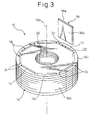
- Figs. 3, 4A and 4B are illustrations respectively showing a rotor 12 of an electric motor, which can be manufactured by using the mold 10.
- the rotor 12 includes a rotor core 16 having a plurality of (eight, in the drawing) magnet-retaining apertures 14 and a plurality of (eight, in the drawing) permanent magnets 18 individually received and retained in the plurality of magnet-retaining apertures 14 of the rotor core 16.
- the rotor core 16 is a substantially cylindrical member formed by stacking or laminating magnetic sheets, such as silicon steel plates, and is provided at a center thereof with a shaft hole 20 penetrating therethrough along an axis 16a (Fig. 3).
- the plurality of magnet-retaining apertures 14 are formed respectively as axially-extending through holes, and are disposed in proximity to an outer circumferential surface 16b of the rotor core 16 and in a predetermined, circumferentially regular-interval arrangement about the axis 16a.
- Each of the magnet-retaining apertures 14 has a slot-like profile substantially corresponding to a tabular profile of the permanent magnet 18 as to be retained.
- Relatively thin marginal portions 16c are formed in the respective magnetic sheets between the magnet-retaining apertures 14 and the outer circumferential surface 16b of the rotor core 16.
- the rotor core 16 is attached to a shaft (not shown) at a shaft hole 20 by, for example, a shrinkage fit, with the permanent magnets 18 being securely retained in the respective magnet-retaining apertures 14.
- the rotor 12 having the shaft is rotatably supported on a housing (not shown) in a state where the outer circumferential surface 16b of the rotor core 16 opposes a stator (not shown) with a predetermined air-gap defined therebetween, whereby an electric motor is constituted.
- Each of the permanent magnets 18 has a flat shape which is substantially rectangular as seen in a plan view, and is magnetized or polarized in a thickness direction so as to form N and S poles respectively in a pair of major surfaces 18a thereof (Fig. 3).
- the permanent magnets 18 are individually inserted into the corresponding magnet-retaining apertures 14 in an alternate arrangement where the mutually-different magnetic poles of the permanent magnets 18 disposed side-by-side in a circumferential direction are oriented toward the outer circumferential surface 16b of the rotor core 16.
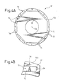
- magnetic poles corresponding to those of the nearest permanent magnets 18 are formed on the outer circumferential surface 16b of the rotor core 16 in a circumferentially alternate arrangement (Fig. 4A) .
- Each of the magnet-retaining apertures 14 is provided with a pair of grooves 22 continuously extending in the axial direction and formed at longitudinally opposite ends of each aperture 14 as seen in the plan view of Fig. 4A.
- the grooves 22 of each magnet-retaining aperture 14 are disposed to oppose to a pair of lateral edges of the permanent magnet 18 received in the aperture 14, so as to form gaps 24 having predetermined shapes between the magnet-retaining aperture 14 and the permanent magnet 18 (Fig. 4B).
- the mold 10 is used to fill the respective gaps 24 with a molten resinous material by, for example, an injection molding machine (not shown).
- the mold 10 includes a cavity 26 for accommodating the rotor core 16 at a predetermined position, with the rotor core 16 receiving the plurality of permanent magnets 18 individually in the plurality of magnet-retaining apertures 14 (Fig. 4A); and a deformation inhibiting surface 28 provided in the cavity 26 and coming into at least local contact with the outer circumferential surface 16b of the rotor core 16, during a period when the molten resinous material is poured into the plurality of gaps 24, to inhibit a bulging deformation of the outer circumferential surface 16b (Fig. 1).
- the mold 10 is constructed from a mutually-combined pair of mold members 30, 32 separable from each other at a parting line 10a, and is mounted on a mold clamping mechanism of the injection molding machine (not shown) with one mold member 30 being carried on a stationary platen (not shown) and the other mold member 32 being carried on a movable platen (not shown).
- the mold member 30 at a stationary side is provided with a material passage (including a sprue, a runner and a gate) 36, for distributing the flow of the molten resinous material in predetermined directions, which is supplied from an injection mechanism (a part of a nozzle 34 is shown) of the injection molding machine.
- the mold member 32 at a movable side is provided with the cavity 26 and the deformation inhibiting surface 28, described above.
- the material passage 36 of the mold member 30 is configured in such a manner that the molten resinous material can be appropriately distributed and poured into each of the plurality of gaps 24 defined between the magnet-retaining apertures 14 and the permanent magnets 18 (Figs. 4A and 4B) in the rotor core 16 disposed at a position in the cavity 26 proper for a pouring of the resinous material.
- the mold member 30 has a known two-piece structure (i.e., a first element 30a and a second element 30b) for removing the resinous material solidified in the material passage 36.
- the second element 30b of the mold member 30 has an end face 30c constituting the parting line 10a, and a plurality of gates 36a of the material passage 36 are opened in the end face 30c.
- the mold member 32 has a known two-piece structure (i.e., a first element 32a and a second element 32b) for incorporating thereto an ejector mechanism (not shown) and the like.
- the mold member 32 is provided with a centering support element 38 extending into the cavity 26 (and fixed to the first element 32a, in the drawing).
- the centering support element 38 is shaped and dimensioned to be fittable into the shaft hole 20 (Fig. 3) of the rotor core 16 with no wobbling, and locates the rotor core 16, accommodated in the cavity 26, at the proper position for the pouring of the resinous material with reference to the axis 16a.
- the deformation inhibiting surface 28 provided in the cavity 26 is disposed to oppose to, and to be capable of coming into contact with, the substantially entire outer circumferential surface 16b of the rotor core 16.
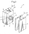
- the second element 32b of the mold member 32 is provided with a recess 40 having a substantially rectangular shape as seen in a plan view, with the centering support element 38 protruding into the center thereof, and an annular insert mold 42 is securely provided in the recess 40 (Fig. 2).
- the recess 40 in the second element 32b of the mold member 32 and the insert mold 42 cooperate with each other to define the cavity 26, and an annular inner circumferential surface of the insert mold 42 acts as the deformation inhibiting surface 28.
- the cavity 26 and the deformation inhibiting surface 28 may be formed directly in the second element 32b of the mold member 32.
- a bottom surface (i.e., an axial end face) 40a of the recess 40 of the mold member 32 cooperates with the end face 30c of the second element 30b of the mold member 30 to firmly and securely hold the rotor core 16 accommodated in the cavity 26.
- the bottom surface 40a of the recess 40 of the mold member 32 is tightly abutted against one axial end face of the rotor core 16 and thereby acts as a forming surface 40a hermetically closing openings at the axial ends of the gaps 24 (Figs. 4A, 4B) formed between the respective magnet-retaining apertures 14 and the respective permanent magnets 18.
- the deformation inhibiting surface 28 provided in the cavity 26 comes, at least locally, into contact with the outer circumferential surface 16b of the rotor core 16, during the period when the molten resinous material is poured into the gaps 24 between the respective magnet-retaining apertures 14 formed in the rotor core 16 and the respective permanent magnets 18, to prevent the outer circumferential surface 16b from being bulgingly deformed. Therefore, it is possible to accurately pour the molten resinous material into the plurality of gaps 24 of the rotor core 16 at a required high injection pressure, while surely inhibiting the deformation of the rotor core 16, in particular, the deformation of the outer circumferential surface 16b thereof.
- the molten resinous material poured into the gaps 24 under the required injection pressure entirely fills up the gaps 24, so as to firmly and mechanically couple the rotor core 16 with the permanent magnets 18.
- the resinous material molded in the gaps 24 is preferably selected from engineering plastics that have excellent fluidity and mechanical strength.
- a minute clearance of 0.2 mm or less (a radial dimension) is defined between the outer circumferential surface 16b of the rotor core 16 accommodated in the cavity 26 and the deformation inhibiting surface 28 provided in the cavity 26.
- the minute clearance facilitates the insertion of the rotor core 16 into the cavity 26, and allows the rotor core 16 to be smoothly detached from the cavity 26 after the resinous material is molded in the gaps 24.
- the injection pressure may cause a deformation in the marginal portions 16c of the rotor core 16 by an amount corresponding to the minute clearance.
- the clearance is 0.2 mm or less, the deformation in the marginal portions 16c does not substantially affect a magnetic flux passing through the rotor core 16, and a possible contact of the rotor core 16 with the stator core is eliminated, during the rotation of the rotor 12.
- the rotor core 16 is inserted into the cavity 26 by an automatic machine such as a robot (not shown), that a sufficient space for a holding element (e.g., a hand) for holding the rotor core 16 is obtained between the rotor core 16 and the cavity 26. Therefore, in the case where the automatic machine is used, it is advisable that the centering support element 38 of the mold member 32 is inserted halfway into the shaft hole 20 of the rotor core 16 by the automatic machine, and thereafter the rotor core 16 is pushed into the cavity 26 completely by the mold closing operation of the mold clamping mechanism of an injection molding machine, as shown in, e.g., Fig. 2.
- Fig. 5 shows a mold 50, according to another embodiment of the present invention, in a state where a rotor core 16 is accommodated in a cavity 26.
- the mold 50 has a configuration substantially identical to that of the mold 10 described above, except for the configuration of a deformation inhibiting surface provided in the cavity 26. Therefore, corresponding components are designated by common reference numerals, and the descriptions thereof are not repeated.
- the mold 50 includes the cavity 26 for accommodating the rotor core 16 (Fig. 4A) at a predetermined position; and a deformation inhibiting surface 52 provided in the cavity 26 and coming into local contact with the outer circumferential surface 16b of the rotor core 16, during a period when a molten resinous material is poured into a plurality of gaps 24 formed in the rotor core 16, to inhibit a bulging deformation of the outer circumferential surface 16b.
- the deformation inhibiting surface 52 is provided in proximity to gates 36a for the molten resinous material, the gates 36a opening to the cavity 26, and is disposed to oppose to, and to be capable of coming into contact with, a local area of the outer circumferential surface 16b of the rotor core 16, the local area corresponding to a gap region defined in a predetermined length from a resin pouring end of each gap 24 when the resin pouring end is connected to each gate 36a (i.e., an area adjacent to the axial end face of the rotor core 16, abutting against the end face 30c of the mold member 30).
- annular insert mold 54 is securely provided in a recess 40 formed in a second element 32b of a mold member 32.
- the recess 40 of the mold member 32 and the insert mold 54 cooperate with each other to define the cavity 26, and one axial end area (a right end area, in the drawing) of an annular inner circumferential surface of the insert mold 54 acts as the deformation inhibiting surface 52.
- the remaining area of the annular inner circumferential surface of the insert mold 54 is disposed to oppose to, and to be unable to come into contact with, the outer circumferential surface 16b of the rotor core 16 accommodated in the cavity 26, with a clearance larger than 0.2 mm defined therebetween.
- the cavity 26 and the deformation inhibiting surface 52 may be formed directly in the second element 32b of the mold member 32.
- the deformation inhibiting surface 52 provided in the cavity 26 comes into contact with the local area of the outer circumferential surface 16b of the rotor core 16, the local area being adjacent to the rotor core end face facing toward the gates 36a, during the period when the molten resinous material is poured into the gaps 24 in the rotor core 16, to also prevent the outer circumferential surface 16b from being bulgingly deformed. Therefore, in a manner similar to the mold 10 described above, it is possible, by using the mold 50, to accurately and sufficiently pour the molten resinous material into the plurality of gaps 24, while surely inhibiting the deformation of the rotor core 16, and in particular, the deformation of the outer circumferential surface 16b thereof.
- the mold 50 it is possible to inhibit the bulging deformation of an area, as to be probably deformed, in the outer circumferential surface 16b of the rotor core 16. Moreover, there is an advantage that the deformation inhibiting surface 52 provided in the cavity 26 is disposed adjacent to only the local area of the outer circumferential surface 16b of the rotor core 16 and, thereby, the insertion of the rotor core 16 into the cavity 26 is significantly facilitated.
Landscapes
- Engineering & Computer Science (AREA)
- Manufacturing & Machinery (AREA)
- Power Engineering (AREA)
- Permanent Field Magnets Of Synchronous Machinery (AREA)
- Manufacture Of Motors, Generators (AREA)
- Iron Core Of Rotating Electric Machines (AREA)
Abstract
Description
- The present invention relates to a mold used for manufacturing a rotor of an electric motor.
- In a rotor of an electric motor having a permanent-magnet field system (e.g., a synchronous motor), it is known that a plurality of permanent magnets are mounted in an embedded manner at predetermined positions in a cylindrical rotor core formed by stacking or laminating magnetic sheets such as silicon steel plates. The rotor of this type is typically manufactured by preliminarily forming a plurality of magnet-retaining apertures (typically, axially-extending through holes) in a predetermined circumferentially-distributed arrangement about a rotor shaft, each aperture having a profile substantially corresponding to a profile of each permanent magnet; inserting respectively the plurality of permanent magnets into the magnet-retaining apertures; and fixing each permanent magnet by an adhesive or an impregnant.
- In the above-described conventional method for manufacturing a rotor, in the case where the adhesive is used for fixing the magnets, relatively complicated manual operations, such as the application of the adhesive to the permanent magnets, the removal of the surplus adhesive leaking from the magnet-retaining apertures, and the like, may be required. Also, in the case where the impregnant is used for fixing the magnets, relatively large-scale equipment tends to be required for an immersion process for immersing the rotor core in the impregnant, a heating process for solidifying the impregnant, etc., and thus the number of manufacturing steps tends to increase. On the other hand, it is also known that, as a rotor manufacturing method capable of resolving the above inconveniences, the rotor core is previously fabricated so that predetermined gaps are formed between respective magnet-retaining apertures and respective permanent magnets, and a resinous material is locally pored into the gaps and solidified therein, so as to fix the permanent magnets to the rotor core (e.g., see Japanese Unexamined Patent Publication (Kokai)
No. 5-83892 JP-A-5-083892 - In the rotor manufacturing method disclosed in
JP-A-5-083892 - In the rotor manufacturing method adopting the injection molding technique set forth in the above-described
JP-A-5-083892 - It is an object of the present invention to provide a mold used in a manufacturing process of a rotor of an electric motor having a permanent-magnet field system, for poring a resinous material into gaps between respective magnet-retaining apertures formed in a rotor core and respective permanent magnets, wherein the deformation of the rotor core can be surely inhibited and the resinous material can be accurately and sufficiently poured into the gaps in the rotor core and, thereby, an electric motor rotor having excellent operational reliability can be manufactured.
- To accomplish the above object, the present invention provides a mold used in a manufacturing process of a rotor of an electric motor, the rotor including a rotor core with a plurality of magnet-retaining apertures and a plurality of permanent magnets individually received and retained in the plurality of magnet-retaining apertures of the rotor core, for pouring a resinous material into gaps defined between the respective magnet-retaining apertures and the respective permanent magnets, the mold comprising a cavity for accommodating the rotor core at a predetermined position, with the rotor core receiving the plurality of permanent magnets individually in the plurality of magnet-retaining apertures; and a deformation inhibiting surface provided in the cavity and coming into at least local contact with an outer circumferential surface of the rotor core, during a period when the resinous material is poured into the gaps, to inhibit a bulging deformation of the outer circumferential surface.
- In the mold having the above configuration, the deformation inhibiting surface may be provided in proximity to a gate for a molten resinous material, the gate opening to the cavity, and may be disposed to oppose to, and to be capable of coming into contact with, a local area of the outer circumferential surface of the rotor core, the local area corresponding to a gap region defined in a predetermined length from a resin pouring end of each gap when the resin pouring end is connected to the gate.
- Also, in a state where the outer circumferential surface of the rotor core is not deformed, a clearance of 0.2 mm or less may be defined between the outer circumferential surface of the rotor core accommodated in the cavity and the deformation inhibiting surface provided in the cavity.
- The above and other objects, features and advantages of the present invention will become more apparent from the following description of preferred embodiments in connection with the accompanying drawings, wherein:
- Fig. 1 is a sectional view showing a mold according to an embodiment of the present invention with a rotor core being accommodated in a cavity;
- Fig. 2 is a perspective view showing the mold of Fig. 1 in an opened state;
- Fig. 3 is a perspective view showing a rotor of an electric motor, which can be manufactured by using the mold of Fig. 1;
- Fig. 4A is a plan view of the rotor of Fig. 3;
- Fig. 4B is an enlarged view of a major part of the rotor of Fig. 3; and
- Fig. 5 is a sectional view showing a mold according to another embodiment of the present invention with a rotor core being accommodated in a cavity.
- The embodiments of the present invention are described below, in detail, with reference to the accompanying drawings. In the drawings, the same or similar components are denoted by common reference numerals.
- Referring to the drawings, Figs. 1 and 2 are illustrations respectively showing a
mold 10 according to an embodiment of the present invention, and Figs. 3, 4A and 4B are illustrations respectively showing arotor 12 of an electric motor, which can be manufactured by using themold 10. Therotor 12 includes arotor core 16 having a plurality of (eight, in the drawing) magnet-retaining apertures 14 and a plurality of (eight, in the drawing)permanent magnets 18 individually received and retained in the plurality of magnet-retaining apertures 14 of therotor core 16. - The
rotor core 16 is a substantially cylindrical member formed by stacking or laminating magnetic sheets, such as silicon steel plates, and is provided at a center thereof with ashaft hole 20 penetrating therethrough along anaxis 16a (Fig. 3). The plurality of magnet-retaining apertures 14 are formed respectively as axially-extending through holes, and are disposed in proximity to an outercircumferential surface 16b of therotor core 16 and in a predetermined, circumferentially regular-interval arrangement about theaxis 16a. Each of the magnet-retaining apertures 14 has a slot-like profile substantially corresponding to a tabular profile of thepermanent magnet 18 as to be retained. Relatively thinmarginal portions 16c are formed in the respective magnetic sheets between the magnet-retaining apertures 14 and the outercircumferential surface 16b of therotor core 16. - The
rotor core 16 is attached to a shaft (not shown) at ashaft hole 20 by, for example, a shrinkage fit, with thepermanent magnets 18 being securely retained in the respective magnet-retaining apertures 14. Therotor 12 having the shaft is rotatably supported on a housing (not shown) in a state where the outercircumferential surface 16b of therotor core 16 opposes a stator (not shown) with a predetermined air-gap defined therebetween, whereby an electric motor is constituted. - Each of the
permanent magnets 18 has a flat shape which is substantially rectangular as seen in a plan view, and is magnetized or polarized in a thickness direction so as to form N and S poles respectively in a pair ofmajor surfaces 18a thereof (Fig. 3). Thepermanent magnets 18 are individually inserted into the corresponding magnet-retaining apertures 14 in an alternate arrangement where the mutually-different magnetic poles of thepermanent magnets 18 disposed side-by-side in a circumferential direction are oriented toward the outercircumferential surface 16b of therotor core 16. In this state, magnetic poles corresponding to those of the nearestpermanent magnets 18 are formed on the outercircumferential surface 16b of therotor core 16 in a circumferentially alternate arrangement (Fig. 4A) . - Each of the magnet-
retaining apertures 14 is provided with a pair ofgrooves 22 continuously extending in the axial direction and formed at longitudinally opposite ends of eachaperture 14 as seen in the plan view of Fig. 4A. Thegrooves 22 of each magnet-retaining aperture 14 are disposed to oppose to a pair of lateral edges of thepermanent magnet 18 received in theaperture 14, so as to formgaps 24 having predetermined shapes between the magnet-retaining aperture 14 and the permanent magnet 18 (Fig. 4B). Themold 10 is used to fill therespective gaps 24 with a molten resinous material by, for example, an injection molding machine (not shown). - The
mold 10 includes acavity 26 for accommodating therotor core 16 at a predetermined position, with therotor core 16 receiving the plurality ofpermanent magnets 18 individually in the plurality of magnet-retaining apertures 14 (Fig. 4A); and adeformation inhibiting surface 28 provided in thecavity 26 and coming into at least local contact with the outercircumferential surface 16b of therotor core 16, during a period when the molten resinous material is poured into the plurality ofgaps 24, to inhibit a bulging deformation of the outercircumferential surface 16b (Fig. 1). In the illustrated embodiment, themold 10 is constructed from a mutually-combined pair ofmold members mold member 30 being carried on a stationary platen (not shown) and theother mold member 32 being carried on a movable platen (not shown). Themold member 30 at a stationary side is provided with a material passage (including a sprue, a runner and a gate) 36, for distributing the flow of the molten resinous material in predetermined directions, which is supplied from an injection mechanism (a part of anozzle 34 is shown) of the injection molding machine. On the other hand, themold member 32 at a movable side is provided with thecavity 26 and thedeformation inhibiting surface 28, described above. - The
material passage 36 of themold member 30 is configured in such a manner that the molten resinous material can be appropriately distributed and poured into each of the plurality ofgaps 24 defined between the magnet-retaining apertures 14 and the permanent magnets 18 (Figs. 4A and 4B) in therotor core 16 disposed at a position in thecavity 26 proper for a pouring of the resinous material. In this connection, themold member 30 has a known two-piece structure (i.e., afirst element 30a and asecond element 30b) for removing the resinous material solidified in thematerial passage 36. Thesecond element 30b of themold member 30 has anend face 30c constituting the parting line 10a, and a plurality ofgates 36a of thematerial passage 36 are opened in theend face 30c. On the other hand, themold member 32 has a known two-piece structure (i.e., afirst element 32a and asecond element 32b) for incorporating thereto an ejector mechanism (not shown) and the like. - The
mold member 32 is provided with acentering support element 38 extending into the cavity 26 (and fixed to thefirst element 32a, in the drawing). Thecentering support element 38 is shaped and dimensioned to be fittable into the shaft hole 20 (Fig. 3) of therotor core 16 with no wobbling, and locates therotor core 16, accommodated in thecavity 26, at the proper position for the pouring of the resinous material with reference to theaxis 16a. In a state where therotor core 16 is attached to thecentering support element 38, thedeformation inhibiting surface 28 provided in thecavity 26 is disposed to oppose to, and to be capable of coming into contact with, the substantially entire outercircumferential surface 16b of therotor core 16. - In the illustrated embodiment, the
second element 32b of themold member 32 is provided with arecess 40 having a substantially rectangular shape as seen in a plan view, with the centeringsupport element 38 protruding into the center thereof, and anannular insert mold 42 is securely provided in the recess 40 (Fig. 2). Therecess 40 in thesecond element 32b of themold member 32 and theinsert mold 42 cooperate with each other to define thecavity 26, and an annular inner circumferential surface of theinsert mold 42 acts as thedeformation inhibiting surface 28. In this connection, in place of the illustrated configuration, thecavity 26 and thedeformation inhibiting surface 28 may be formed directly in thesecond element 32b of themold member 32. - A bottom surface (i.e., an axial end face) 40a of the
recess 40 of themold member 32 cooperates with theend face 30c of thesecond element 30b of themold member 30 to firmly and securely hold therotor core 16 accommodated in thecavity 26. In this situation, thebottom surface 40a of therecess 40 of themold member 32 is tightly abutted against one axial end face of therotor core 16 and thereby acts as a formingsurface 40a hermetically closing openings at the axial ends of the gaps 24 (Figs. 4A, 4B) formed between the respective magnet-retainingapertures 14 and the respectivepermanent magnets 18. - In the
mold 10 configured as described above, thedeformation inhibiting surface 28 provided in thecavity 26 comes, at least locally, into contact with the outercircumferential surface 16b of therotor core 16, during the period when the molten resinous material is poured into thegaps 24 between the respective magnet-retainingapertures 14 formed in therotor core 16 and the respectivepermanent magnets 18, to prevent the outercircumferential surface 16b from being bulgingly deformed. Therefore, it is possible to accurately pour the molten resinous material into the plurality ofgaps 24 of therotor core 16 at a required high injection pressure, while surely inhibiting the deformation of therotor core 16, in particular, the deformation of the outercircumferential surface 16b thereof. The molten resinous material poured into thegaps 24 under the required injection pressure entirely fills up thegaps 24, so as to firmly and mechanically couple therotor core 16 with thepermanent magnets 18. As a result, it is possible, by using themold 10, to ensure a sufficient fixing strength of thepermanent magnets 18 with high reproducibility, and thus to manufacture therotor 12 of an electric motor with a high yield, therotor 12 including therotor core 16 with no deformation and having excellent operational reliability. In this connection, the resinous material molded in thegaps 24 is preferably selected from engineering plastics that have excellent fluidity and mechanical strength. - In the above configuration, it is desirable that, in a state where the outer
circumferential surface 16b of therotor core 16 is not deformed (e.g., in an initial state before the resin is poured), a minute clearance of 0.2 mm or less (a radial dimension) is defined between the outercircumferential surface 16b of therotor core 16 accommodated in thecavity 26 and thedeformation inhibiting surface 28 provided in thecavity 26. The minute clearance facilitates the insertion of therotor core 16 into thecavity 26, and allows therotor core 16 to be smoothly detached from thecavity 26 after the resinous material is molded in thegaps 24. - In this arrangement, during the period when the molten resinous material is poured into the
gaps 24, it is speculated that the injection pressure may cause a deformation in themarginal portions 16c of therotor core 16 by an amount corresponding to the minute clearance. However, if the clearance is 0.2 mm or less, the deformation in themarginal portions 16c does not substantially affect a magnetic flux passing through therotor core 16, and a possible contact of therotor core 16 with the stator core is eliminated, during the rotation of therotor 12. Further, even if the injection pressure deforms themarginal portions 16c of therotor core 16 by the amount of the minute clearance and thereby the outercircumferential surface 16b comes into contact with thedeformation inhibiting surface 28, such a deformation is typically caused only in a local area of the outercircumferential surface 16b corresponding to a gap region defined in a predetermined length from a resin pouring end of eachgap 24 when the resin pouring end is connected with eachgate 36a of the mold member 30 (i.e., in an area adjacent to the axial end face of therotor core 16, abutting against theend face 30c of the mold member 30) and, therefore, the deformation does not interfere with the smooth detachment of therotor core 16 after the resinous material is molded. - In the
mold 10 configured as described above, it may be difficult, for example, if therotor core 16 is inserted into thecavity 26 by an automatic machine such as a robot (not shown), that a sufficient space for a holding element (e.g., a hand) for holding therotor core 16 is obtained between therotor core 16 and thecavity 26. Therefore, in the case where the automatic machine is used, it is advisable that the centeringsupport element 38 of themold member 32 is inserted halfway into theshaft hole 20 of therotor core 16 by the automatic machine, and thereafter therotor core 16 is pushed into thecavity 26 completely by the mold closing operation of the mold clamping mechanism of an injection molding machine, as shown in, e.g., Fig. 2. - Fig. 5 shows a
mold 50, according to another embodiment of the present invention, in a state where arotor core 16 is accommodated in acavity 26. Themold 50 has a configuration substantially identical to that of themold 10 described above, except for the configuration of a deformation inhibiting surface provided in thecavity 26. Therefore, corresponding components are designated by common reference numerals, and the descriptions thereof are not repeated. - The
mold 50 includes thecavity 26 for accommodating the rotor core 16 (Fig. 4A) at a predetermined position; and adeformation inhibiting surface 52 provided in thecavity 26 and coming into local contact with the outercircumferential surface 16b of therotor core 16, during a period when a molten resinous material is poured into a plurality ofgaps 24 formed in therotor core 16, to inhibit a bulging deformation of the outercircumferential surface 16b. Thedeformation inhibiting surface 52 is provided in proximity togates 36a for the molten resinous material, thegates 36a opening to thecavity 26, and is disposed to oppose to, and to be capable of coming into contact with, a local area of the outercircumferential surface 16b of therotor core 16, the local area corresponding to a gap region defined in a predetermined length from a resin pouring end of eachgap 24 when the resin pouring end is connected to eachgate 36a (i.e., an area adjacent to the axial end face of therotor core 16, abutting against theend face 30c of the mold member 30). - In the illustrated embodiment, an
annular insert mold 54 is securely provided in arecess 40 formed in asecond element 32b of amold member 32. Therecess 40 of themold member 32 and theinsert mold 54 cooperate with each other to define thecavity 26, and one axial end area (a right end area, in the drawing) of an annular inner circumferential surface of theinsert mold 54 acts as thedeformation inhibiting surface 52. The remaining area of the annular inner circumferential surface of theinsert mold 54 is disposed to oppose to, and to be unable to come into contact with, the outercircumferential surface 16b of therotor core 16 accommodated in thecavity 26, with a clearance larger than 0.2 mm defined therebetween. In this connection, in place of the illustrated configuration, thecavity 26 and thedeformation inhibiting surface 52 may be formed directly in thesecond element 32b of themold member 32. - In the
mold 50 configured as described above, thedeformation inhibiting surface 52 provided in thecavity 26 comes into contact with the local area of the outercircumferential surface 16b of therotor core 16, the local area being adjacent to the rotor core end face facing toward thegates 36a, during the period when the molten resinous material is poured into thegaps 24 in therotor core 16, to also prevent the outercircumferential surface 16b from being bulgingly deformed. Therefore, in a manner similar to themold 10 described above, it is possible, by using themold 50, to accurately and sufficiently pour the molten resinous material into the plurality ofgaps 24, while surely inhibiting the deformation of therotor core 16, and in particular, the deformation of the outercircumferential surface 16b thereof. As a result, it is possible to ensure a sufficient fixing strength of thepermanent magnets 18 with high reproducibility, and thus to manufacture therotor 12 of an electric motor with high yield, therotor 12 including therotor core 16 with no deformation and having excellent operational reliability. - In particular, in the
mold 50, it is possible to inhibit the bulging deformation of an area, as to be probably deformed, in the outercircumferential surface 16b of therotor core 16. Moreover, there is an advantage that thedeformation inhibiting surface 52 provided in thecavity 26 is disposed adjacent to only the local area of the outercircumferential surface 16b of therotor core 16 and, thereby, the insertion of therotor core 16 into thecavity 26 is significantly facilitated. - While the invention has been described with reference to specific preferred embodiments, it will be understood, by those skilled in the art, that various changes and modifications may be made thereto without departing from the scope of the following claims.
Claims (3)
- A mold (10) used in a manufacturing process of a rotor (12) of an electric motor, the rotor including a rotor core (16) with a plurality of magnet-retaining apertures (14) and a plurality of permanent magnets (18) individually received and retained in the plurality of magnet-retaining apertures of the rotor core, for pouring a resinous material into gaps (24) defined between the respective magnet-retaining apertures and the respective permanent magnets, characterized in that the mold comprising:a cavity (26) for accommodating the rotor core at a predetermined position, with the rotor core receiving the plurality of permanent magnets individually in the plurality of magnet-retaining apertures; anda deformation inhibiting surface (28) provided in said cavity and coming into at least local contact with an outer circumferential surface (16b) of the rotor core, during a period when the resinous material is poured into the gaps, to inhibit a bulging deformation of the outer circumferential surface.
- A mold as set forth in claim 1, wherein said deformation inhibiting surface is provided in proximity to a gate (36a) for a molten resinous material, said gate opening to said cavity, and is disposed to oppose to, and to be capable of coming into contact with, a local area of the outer circumferential surface of the rotor core, the local area corresponding to a gap region defined in a predetermined length from a resin pouring end of each gap when the resin pouring end is connected to said gate.
- A mold as set forth in claim 1 or 2, wherein, in a state where the outer circumferential surface of the rotor core is not deformed, a clearance of 0.2 mm or less is defined between the outer circumferential surface of the rotor core accommodated in said cavity and said deformation inhibiting surface provided in said cavity.
Applications Claiming Priority (1)
| Application Number | Priority Date | Filing Date | Title |
|---|---|---|---|
| JP2005349945A JP2007159245A (en) | 2005-12-02 | 2005-12-02 | Mold for use in manufacturing rotor of motor |
Publications (2)
| Publication Number | Publication Date |
|---|---|
| EP1793479A1 true EP1793479A1 (en) | 2007-06-06 |
| EP1793479B1 EP1793479B1 (en) | 2010-01-20 |
Family
ID=37792217
Family Applications (1)
| Application Number | Title | Priority Date | Filing Date |
|---|---|---|---|
| EP06024621A Ceased EP1793479B1 (en) | 2005-12-02 | 2006-11-28 | Mold used for manufacturing electric motor rotor |
Country Status (5)
| Country | Link |
|---|---|
| US (1) | US7500848B2 (en) |
| EP (1) | EP1793479B1 (en) |
| JP (1) | JP2007159245A (en) |
| CN (1) | CN1983773B (en) |
| DE (1) | DE602006011839D1 (en) |
Cited By (4)
| Publication number | Priority date | Publication date | Assignee | Title |
|---|---|---|---|---|
| EP3128657A4 (en) * | 2014-04-02 | 2017-05-24 | Aichi Steel Corporation | Method for manufacturing interior permanent magnet inner rotor and manufacturing device for same |
| EP3915751A1 (en) * | 2020-05-28 | 2021-12-01 | Nidec Corporation | Rotor manufacturing apparatus |
| DE102021107768A1 (en) | 2021-03-26 | 2022-09-29 | Elringklinger Ag | Laminated core and manufacturing process |
| DE102021126750A1 (en) | 2021-10-15 | 2023-04-20 | Schaeffler Technologies AG & Co. KG | Process for manufacturing a rotor for an electrical machine |
Families Citing this family (16)
| Publication number | Priority date | Publication date | Assignee | Title |
|---|---|---|---|---|
| JP4850528B2 (en) * | 2006-02-08 | 2012-01-11 | トヨタ自動車株式会社 | Manufacturing method of rotor |
| JP4842670B2 (en) | 2006-02-27 | 2011-12-21 | トヨタ自動車株式会社 | Rotor and electric vehicle |
| US7919893B2 (en) * | 2008-05-14 | 2011-04-05 | Sunonwealth Electric Machine Industry Co., Ltd. | Permanent magnet rotor with annular rib coupling |
| JP5353388B2 (en) * | 2009-04-06 | 2013-11-27 | トヨタ紡織株式会社 | Resin press-fitting method |
| CN201947080U (en) * | 2011-01-28 | 2011-08-24 | 中山大洋电机制造有限公司 | A brushless motor rotor structure |
| KR20130019088A (en) * | 2011-08-16 | 2013-02-26 | 엘지이노텍 주식회사 | Rotor core of motor |
| JP5681232B2 (en) * | 2013-05-10 | 2015-03-04 | ファナック株式会社 | Electric motor stator injecting resin by injection molding |
| JP6225498B2 (en) * | 2013-06-13 | 2017-11-08 | 日産自動車株式会社 | Magnet fixing device and fixing method to rotor core |
| JP6322519B2 (en) * | 2014-08-19 | 2018-05-09 | 株式会社三井ハイテック | Motor core resin sealing method and apparatus used therefor |
| US10532501B2 (en) * | 2015-05-08 | 2020-01-14 | Kuroda Precision Industries Ltd. | Resin filling device and resin filling method for magnet embedded core |
| JP6298086B2 (en) | 2016-02-24 | 2018-03-20 | ファナック株式会社 | Electric motor rotor and method of manufacturing the same |
| JP6952490B2 (en) * | 2017-04-24 | 2021-10-20 | 株式会社三井ハイテック | Manufacturing method of laminated iron core |
| JP7113694B2 (en) * | 2018-07-31 | 2022-08-05 | 株式会社三井ハイテック | Iron core product manufacturing method and iron core product manufacturing apparatus |
| DE102018214823A1 (en) | 2018-08-31 | 2020-03-05 | Bayerische Motoren Werke Aktiengesellschaft | Injection mold |
| JP2024152331A (en) * | 2023-04-14 | 2024-10-25 | トヨタ紡織株式会社 | Rotor manufacturing equipment |
| US12451774B2 (en) * | 2023-04-26 | 2025-10-21 | Abb Schweiz Ag | Molding parameters for injection molded rotor production |
Citations (4)
| Publication number | Priority date | Publication date | Assignee | Title |
|---|---|---|---|---|
| JPH01231642A (en) * | 1988-03-11 | 1989-09-14 | Toshiba Corp | Manufacture of cast rotor core |
| JPH0340740A (en) * | 1990-05-21 | 1991-02-21 | Casio Comput Co Ltd | Manufacturing method of rotor for step motor |
| JP2000166190A (en) * | 1998-11-30 | 2000-06-16 | Toshiba Corp | Permanent magnet type motor rotor manufacturing apparatus and permanent magnet type motor manufacturing method |
| EP1176700A2 (en) * | 2000-07-27 | 2002-01-30 | Yamaha Hatsudoki Kabushiki Kaisha | Embedded magnet type rotor, manufacturing method and mold device |
Family Cites Families (3)
| Publication number | Priority date | Publication date | Assignee | Title |
|---|---|---|---|---|
| JPH0583892A (en) | 1991-09-19 | 1993-04-02 | Seiko Epson Corp | Permanent magnet rotor |
| JP2000354342A (en) | 1999-06-07 | 2000-12-19 | Mitsubishi Heavy Ind Ltd | Magnet motor manufacturing method, magnet motor and hermetic compressor provided with the magnet motor |
| JP3887541B2 (en) | 2001-02-16 | 2007-02-28 | 三菱電機株式会社 | Embedded magnet rotor |
-
2005
- 2005-12-02 JP JP2005349945A patent/JP2007159245A/en active Pending
-
2006
- 2006-11-28 EP EP06024621A patent/EP1793479B1/en not_active Ceased
- 2006-11-28 DE DE602006011839T patent/DE602006011839D1/en active Active
- 2006-11-29 US US11/564,652 patent/US7500848B2/en active Active
- 2006-12-01 CN CN2006101633651A patent/CN1983773B/en not_active Expired - Fee Related
Patent Citations (4)
| Publication number | Priority date | Publication date | Assignee | Title |
|---|---|---|---|---|
| JPH01231642A (en) * | 1988-03-11 | 1989-09-14 | Toshiba Corp | Manufacture of cast rotor core |
| JPH0340740A (en) * | 1990-05-21 | 1991-02-21 | Casio Comput Co Ltd | Manufacturing method of rotor for step motor |
| JP2000166190A (en) * | 1998-11-30 | 2000-06-16 | Toshiba Corp | Permanent magnet type motor rotor manufacturing apparatus and permanent magnet type motor manufacturing method |
| EP1176700A2 (en) * | 2000-07-27 | 2002-01-30 | Yamaha Hatsudoki Kabushiki Kaisha | Embedded magnet type rotor, manufacturing method and mold device |
Cited By (8)
| Publication number | Priority date | Publication date | Assignee | Title |
|---|---|---|---|---|
| EP3128657A4 (en) * | 2014-04-02 | 2017-05-24 | Aichi Steel Corporation | Method for manufacturing interior permanent magnet inner rotor and manufacturing device for same |
| US10454353B2 (en) | 2014-04-02 | 2019-10-22 | Aichi Steel Corporation | Apparatus for manufacturing interior permanent magnet-type inner rotor and manufacturing method using same |
| US11165315B2 (en) | 2014-04-02 | 2021-11-02 | Aichi Steel Corporation | Method and apparatus for manufacturing interior permanent magnet-type inner rotor |
| EP3915751A1 (en) * | 2020-05-28 | 2021-12-01 | Nidec Corporation | Rotor manufacturing apparatus |
| DE102021107768A1 (en) | 2021-03-26 | 2022-09-29 | Elringklinger Ag | Laminated core and manufacturing process |
| DE102021126750A1 (en) | 2021-10-15 | 2023-04-20 | Schaeffler Technologies AG & Co. KG | Process for manufacturing a rotor for an electrical machine |
| DE102021126750B4 (en) | 2021-10-15 | 2023-06-22 | Schaeffler Technologies AG & Co. KG | Process for manufacturing a rotor for an electrical machine |
| US12592593B2 (en) | 2021-10-15 | 2026-03-31 | Schaeffler Technologies AG & Co. KG | Rotor, method for manufacturing a rotor, and electric machine |
Also Published As
| Publication number | Publication date |
|---|---|
| CN1983773B (en) | 2010-05-19 |
| US7500848B2 (en) | 2009-03-10 |
| CN1983773A (en) | 2007-06-20 |
| JP2007159245A (en) | 2007-06-21 |
| DE602006011839D1 (en) | 2010-03-11 |
| US20070128307A1 (en) | 2007-06-07 |
| EP1793479B1 (en) | 2010-01-20 |
Similar Documents
| Publication | Publication Date | Title |
|---|---|---|
| EP1793479B1 (en) | Mold used for manufacturing electric motor rotor | |
| EP1801955B1 (en) | Electric motor rotor and method of manufacturing the same | |
| US6370761B2 (en) | Method of making a rotor for an electric motor | |
| JP5315967B2 (en) | Rotating electrical machine rotor manufacturing method and rotor | |
| US20070134368A1 (en) | Mold used for manufacturing electric motor rotor | |
| EP3395532B1 (en) | Bonded-magnet injection molding device and bonded-magnet injection molding method | |
| JP4708445B2 (en) | Electric motor rotor and method of manufacturing the same | |
| EP3672038A1 (en) | Permanent magnet rotor and its manufacturing method | |
| JP2008245405A (en) | Rotor and method for manufacturing the same | |
| US20200251969A1 (en) | Device for manufacturing rotor core and method for manufacturing rotor core | |
| US20220216750A1 (en) | Device for manufacturing rotor core, method for manufacturing rotor core, and rotor structure | |
| WO2016181421A1 (en) | Resin filling device and resin filling method for magnet embedded core | |
| JP6076288B2 (en) | Rotor manufacturing method, rotor and motor | |
| US11515770B2 (en) | Device for manufacturing rotor core and method for manufacturing rotor core | |
| JP2001246645A (en) | Mold for manufacturing magnet rotor | |
| JPH11226992A (en) | Injection molding method and mold therefor | |
| JP2001246638A (en) | Injection molding method of multicolor molded article and rotor of PM type stepping motor | |
| JP2024159330A (en) | Rotor manufacturing method | |
| US20240380292A1 (en) | Method for manufacturing rotor and rotor | |
| JP2007202242A (en) | Rotor core holding jig | |
| JP4442032B2 (en) | Stepping motor | |
| JP2001246641A (en) | Injection molding method of multicolor molded article and rotor of PM type stepping motor | |
| JPH03277146A (en) | Assembly of permanent magnet rotor |
Legal Events
| Date | Code | Title | Description |
|---|---|---|---|
| PUAI | Public reference made under article 153(3) epc to a published international application that has entered the european phase |
Free format text: ORIGINAL CODE: 0009012 |
|
| AK | Designated contracting states |
Kind code of ref document: A1 Designated state(s): AT BE BG CH CY CZ DE DK EE ES FI FR GB GR HU IE IS IT LI LT LU LV MC NL PL PT RO SE SI SK TR |
|
| AX | Request for extension of the european patent |
Extension state: AL BA HR MK YU |
|
| 17P | Request for examination filed |
Effective date: 20070613 |
|
| 17Q | First examination report despatched |
Effective date: 20070712 |
|
| AKX | Designation fees paid |
Designated state(s): DE |
|
| GRAP | Despatch of communication of intention to grant a patent |
Free format text: ORIGINAL CODE: EPIDOSNIGR1 |
|
| RIN1 | Information on inventor provided before grant (corrected) |
Inventor name: TAMAKI, TAKESHIFANUC DAI3VIRAKARAMATSU Inventor name: MAEDA, TAKUYAROOM 7-104, Inventor name: FUNAKUBO, MAKOTO Inventor name: OKAMOTO, TAKASHIROOM 11-605 |
|
| GRAS | Grant fee paid |
Free format text: ORIGINAL CODE: EPIDOSNIGR3 |
|
| GRAA | (expected) grant |
Free format text: ORIGINAL CODE: 0009210 |
|
| AK | Designated contracting states |
Kind code of ref document: B1 Designated state(s): DE |
|
| REF | Corresponds to: |
Ref document number: 602006011839 Country of ref document: DE Date of ref document: 20100311 Kind code of ref document: P |
|
| PLBE | No opposition filed within time limit |
Free format text: ORIGINAL CODE: 0009261 |
|
| STAA | Information on the status of an ep patent application or granted ep patent |
Free format text: STATUS: NO OPPOSITION FILED WITHIN TIME LIMIT |
|
| 26N | No opposition filed |
Effective date: 20101021 |
|
| REG | Reference to a national code |
Ref country code: DE Ref legal event code: R082 Ref document number: 602006011839 Country of ref document: DE Representative=s name: WUESTHOFF & WUESTHOFF PATENT- UND RECHTSANWAEL, DE |
|
| REG | Reference to a national code |
Ref country code: DE Ref legal event code: R082 Ref document number: 602006011839 Country of ref document: DE Representative=s name: WUESTHOFF & WUESTHOFF PATENT- UND RECHTSANWAEL, DE Effective date: 20111116 Ref country code: DE Ref legal event code: R081 Ref document number: 602006011839 Country of ref document: DE Owner name: FANUC CORPORATION, OSHINO-MURA, JP Free format text: FORMER OWNER: FANUC LTD., YAMANASHI, JP Effective date: 20111116 Ref country code: DE Ref legal event code: R082 Ref document number: 602006011839 Country of ref document: DE Representative=s name: WUESTHOFF & WUESTHOFF, PATENTANWAELTE PARTG MB, DE Effective date: 20111116 |
|
| REG | Reference to a national code |
Ref country code: DE Ref legal event code: R081 Ref document number: 602006011839 Country of ref document: DE Owner name: FANUC CORPORATION, OSHINO-MURA, JP Free format text: FORMER OWNER: FANUC CORP., YAMANASHI, JP Effective date: 20120202 Ref country code: DE Ref legal event code: R082 Ref document number: 602006011839 Country of ref document: DE Representative=s name: WUESTHOFF & WUESTHOFF PATENT- UND RECHTSANWAEL, DE Effective date: 20120202 Ref country code: DE Ref legal event code: R082 Ref document number: 602006011839 Country of ref document: DE Representative=s name: WUESTHOFF & WUESTHOFF, PATENTANWAELTE PARTG MB, DE Effective date: 20120202 |
|
| PGFP | Annual fee paid to national office [announced via postgrant information from national office to epo] |
Ref country code: DE Payment date: 20231003 Year of fee payment: 18 |
|
| REG | Reference to a national code |
Ref country code: DE Ref legal event code: R119 Ref document number: 602006011839 Country of ref document: DE |
|
| PG25 | Lapsed in a contracting state [announced via postgrant information from national office to epo] |
Ref country code: DE Free format text: LAPSE BECAUSE OF NON-PAYMENT OF DUE FEES Effective date: 20250603 |