EP1793290A1 - Robot control device and robot system - Google Patents
Robot control device and robot system Download PDFInfo
- Publication number
- EP1793290A1 EP1793290A1 EP06024612A EP06024612A EP1793290A1 EP 1793290 A1 EP1793290 A1 EP 1793290A1 EP 06024612 A EP06024612 A EP 06024612A EP 06024612 A EP06024612 A EP 06024612A EP 1793290 A1 EP1793290 A1 EP 1793290A1
- Authority
- EP
- European Patent Office
- Prior art keywords
- cable
- control device
- casing
- open
- robot control
- Prior art date
- Legal status (The legal status is an assumption and is not a legal conclusion. Google has not performed a legal analysis and makes no representation as to the accuracy of the status listed.)
- Withdrawn
Links
Images



Classifications
-
- H—ELECTRICITY
- H05—ELECTRIC TECHNIQUES NOT OTHERWISE PROVIDED FOR
- H05K—PRINTED CIRCUITS; CASINGS OR CONSTRUCTIONAL DETAILS OF ELECTRIC APPARATUS; MANUFACTURE OF ASSEMBLAGES OF ELECTRICAL COMPONENTS
- H05K7/00—Constructional details common to different types of electric apparatus
- H05K7/14—Mounting supporting structure in casing or on frame or rack
- H05K7/1462—Mounting supporting structure in casing or on frame or rack for programmable logic controllers [PLC] for automation or industrial process control
- H05K7/1468—Mechanical features of input/output (I/O) modules
- H05K7/1471—Modules for controlling actuators
-
- B—PERFORMING OPERATIONS; TRANSPORTING
- B25—HAND TOOLS; PORTABLE POWER-DRIVEN TOOLS; MANIPULATORS
- B25J—MANIPULATORS; CHAMBERS PROVIDED WITH MANIPULATION DEVICES
- B25J9/00—Program-controlled manipulators
- B25J9/003—Program-controlled manipulators having parallel kinematics
- B25J9/0078—Program-controlled manipulators having parallel kinematics actuated by cables
-
- B—PERFORMING OPERATIONS; TRANSPORTING
- B25—HAND TOOLS; PORTABLE POWER-DRIVEN TOOLS; MANIPULATORS
- B25J—MANIPULATORS; CHAMBERS PROVIDED WITH MANIPULATION DEVICES
- B25J9/00—Program-controlled manipulators
- B25J9/06—Program-controlled manipulators characterised by multi-articulated arms
-
- B—PERFORMING OPERATIONS; TRANSPORTING
- B25—HAND TOOLS; PORTABLE POWER-DRIVEN TOOLS; MANIPULATORS
- B25J—MANIPULATORS; CHAMBERS PROVIDED WITH MANIPULATION DEVICES
- B25J9/00—Program-controlled manipulators
- B25J9/08—Program-controlled manipulators characterised by modular constructions
-
- B—PERFORMING OPERATIONS; TRANSPORTING
- B25—HAND TOOLS; PORTABLE POWER-DRIVEN TOOLS; MANIPULATORS
- B25J—MANIPULATORS; CHAMBERS PROVIDED WITH MANIPULATION DEVICES
- B25J9/00—Program-controlled manipulators
- B25J9/16—Program controls
- B25J9/1679—Program controls characterised by the tasks executed
- B25J9/1682—Dual arm manipulator; Coordination of several manipulators
Definitions
- the present invention relates to a robot control device and a robot system.
- an industrial robot system typically includes a robot control device connected to an industrial robot through a power supply cable or a signal cable. As described in JP-A-2001-67110 and JP-A-2000-66706 , the industrial robot receives a signal from the robot control device and operates in accordance with the signal.
- the size of the space occupied by the robot system be reduced.
- the industrial robot which may be a horizontally or vertically articulated type, includes an increased number of joints, a correspondingly increased number of actuators must be provided for the joints. This increases the diameter of a cable that connects each of the actuators to the robot control device.
- the bending radius of the cable becomes greater when the cable is routed and drawn from the robot control device in a desired direction.
- the cable projects out of the robot control system and occupies an enlarged space, increasing the area occupied by the robot system.
- a robot control device that controls operation of an industrial robot.
- the robot control device is connected to the industrial robot through a connection cable.
- An actuator is provided in the industrial robot.
- the robot control device includes an actuator controller that controls operation of the actuator.
- a casing accommodates the actuator controller.
- the casing has a side surface.
- a connecting portion is connected to the connection cable.
- a stepped portion is provided on the side surface in such a manner that the side surface of the casing has at least one of a projection and a recess.
- the connecting portion is arranged in the stepped portion in such a manner that the connection cable is located on the side surface while extending along the side surface.
- a robot system that includes an industrial robot having an actuator is provided.
- the robot system further includes a robot control device that controls operation of the industrial robot; and a connection cable that connects the industrial robot to the robot control device.
- Fig. 1 is a perspective view showing a robot system according to an embodiment of the present invention
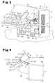
- Fig. 2 is a perspective view showing a casing of a robot control device of Fig. 1;
- Fig. 3 is a side view for explaining operation of an open-close panel of Fig. 2;
- Fig. 4 is a perspective view showing routing of a cable on a stepped surface according to a modification of the invention
- Fig. 5 is a front view showing arrangement of the cable with respect to the open-close panel according to another modification of the invention.
- Fig. 6 is a front view showing arrangement of the cable with respect to the open-close panel according to another modification of the invention.
- Fig. 7 is a front view for explaining arrangement of the cable with respect to the open-close panel according to another modification of the invention.
- a robot system includes an industrial robot RB and a controller 1, or a robot control device that drives the industrial robot RB.
- the industrial robot RB has a four-axis control type horizontally articulated robot arm 60 and a motor 61, which is an actuator that actuates the robot arm 60.
- the controller 1 includes a parallelepiped casing 2, which is placed on an installation surface F.
- the casing 2 has a base 3, a left plate 4, a right plate 5, and a top plate 6.
- the base 3 is arranged on the installation surface F.
- the left plate 4 extends from the left end of the base 3 and the right plate 5 extends from the right end of the base 3.
- the top plate 6 is mounted on the upper end of the left plate 4 and the upper end of the right plate 5.
- the casing 2 further has a back plate 7 and an open-close panel 8.
- the back plate 7 blocks the rear opening of the space defined by the base 3, the left plate 4, the right plate 5, and the top plate 6.
- the open-close panel 8 selectively opens and closes the front opening of this space.
- the upper end of the open-close panel 8 is pivotally supported by the top plate 6 through a pair of left and right hinges H, or support members.
- the open-close panel 8 thus opens or closes the front opening of the casing 2 by pivoting about the hinges H, which is the fulcrum, with respect to the top plate 6.
- the open-close panel 8 is pivotal between a close position illustrated in Fig. 1 and an open position illustrated in Fig. 2.
- the open-close panel 8 has a stepped portion.
- the open-close panel 8 includes a projection 8a projecting from an upper portion of the open-close panel 8 and a guide surface 8b formed in a lower portion of the open-close panel 8.
- the projection 8a projects forward with respect to the guide surface 8b.
- the projection 8a extends throughout the casing 2 in a lateral direction.
- the bottom surface of the projection 8a forms a stepped surface 8c that extends perpendicular to the guide surface 8b.
- the stepped surface 8c extends parallel with the installation surface F.
- the normal direction D of the stepped surface 8c extends perpendicular to the installation surface F.
- the guide surface 8b extends downward from the lower end of the projection 8a.
- the guide surface 8b extends throughout the casing 2 in the lateral direction.
- the guide surface 8b extends perpendicular to the installation surface F.
- a cable guide piece 8d which projects forward, is formed at the lower end of the guide surface 8b.
- the cable guide piece 8d extends throughout the guide surface 8b in the lateral direction.
- the cable guide piece 8d, the guide surface 8b, and the stepped surface 8c define a routing space S.
- the routing space S is a recess located below the open-close panel 8.
- a power cable 22 and a signal cable 32 are routed in the routing space S.
- a rack 10 is provided in the casing 2.
- a plurality of motor drivers 11, which drive a motor 61, are removably received in the rack 10.
- the motor drivers 11 are vertically spaced at predetermined intervals.
- a drive board DB is arranged between the rack 10 and the back plate 7. By inserting the motor drivers 11 into the rack 10, the motor drivers 11 are electrically connected to the drive board DB.
- the drive board DB functions as an actuator control device that controls operation of the motor drivers 11.
- a terminal fixing plate 12 is provided at the right side of the rack 10 in the casing 2.
- An input terminal 13 is secured to the terminal fixing plate 12.
- a power supply cable 14 is connected to the input terminal 13.
- the power supply cable 14 supplies an output current of an external power source to the input terminal 13.
- a stopper 15 is arranged below the input terminal 13 and maintains the open-close panel 8 in an open state. The stopper 15 is capable of maintaining the angle of the open-close panel 8 with respect to the terminal fixing plate 12 at a predetermined value.
- a first power connector 20 is secured to the stepped surface 8c of the open-close panel 8.
- a second power connector 24 is connected to the first power connector 20 from below.
- the power cable 22 extends from the second power connector 24 to the industrial robot RB and supplies power to the industrial robot RB.
- the first power connector 20 functions as a panel power connector and the second power connector 24 functions as a cable power connector.
- the first power connector 20 functions as a connecting portion that is arranged on the stepped surface 8c to connect the power cable 22 to the drive board DB.
- a first signal connector 30 is secured to the stepped surface 8c at the right side of the first power connector 20.
- a second signal connector 34 is connected to the first signal connector 30 from below.
- the signal cable 32 extends from the second signal connector 34 to the industrial robot RB and transmits a prescribed drive signal to the industrial robot RB.
- the first signal connector 30 functions as a panel signal connector and the second signal connector 34 functions as a cable signal connector.
- the first signal connector 30 functions as a connecting portion that is arranged on the stepped surface 8c to connect the signal cable 32 to the drive board DB.
- a cover case 40 that covers the input terminal 13 is arranged on the guide surface 8b at the right side of the first signal connector 30.
- the right wall of the cover case 40 has a recess 40a in which the power supply cable 14 is accommodated and a slit 42 extending from the recess 40a.
- the terminal fixing plate 12 has a power supply switch SW that is manipulated to turn on or off the controller 1.
- the guide surface 8b has a through hole 44 through which the power supply switch SW is passed.
- the through hole 44 is located below the slit 42.
- a front surface 3a of the base 3 includes a first external connector 55 and a second external connector 56.
- a first external cable 53 is capable of connecting a personal computer PC to the first external connector 55.
- a second external cable 54 is capable of connecting a teaching pendant TP to the second external connector 56.
- the first and second external connectors 55, 56 are electrically connected to a non-illustrated CPU board of the controller 1.
- the personal computer PC and the teaching pendant TP provide information necessary for operation of the industrial robot RB to the CPU board.
- the controller 1 is capable of controlling operation of the industrial robot RB. That is, the first external cable 53, the second external cable 54, the first external connector 55, and the second external connector 56 are arranged outside the casing 2, thus saving the space occupied by the controller 1.
- a first internal cable 26 and a second internal cable 36 are accommodated in the casing 2.
- the first internal cable 26 connects the first power connector 20 to the drive board DB.
- the length of the first internal cable 26 is selected in such a manner as to prevent interference with the open-close panel 8 when the open-close panel 8 opens or closes. This prevents a break of the first internal cable 26, a connection failure between the first internal cable 26 and the first power connector 20, and a connection failure between the first internal cable 26 and the drive board DB, regardless of repeated movement of the open-close panel 8.
- first connecting portion J1 between the first power connector 20 and the first internal cable 26 is received in the interior of the projection 8a.
- first arrow A1 of a solid line represents a movement path of the projection 8a when the open-close panel 8 opens and closes.
- Second arrow A2 of a double-dotted chain line represents a movement path of the guide surface 8b when the open-close panel 8 opens or closes.
- the distance between each hinge H and the projection 8a is smaller than the distance between the hinge H and the guide surface 8b. In other words, the path represented by first arrow A1 is shorter than the path represented by second arrow A2.
- the first internal cable 26 of the illustrated embodiment, the first connecting portion J1 of which is received in the projection 8a, is shorter than the first internal cable 26 of a case in which, for example, the first connecting portion J1 is arranged on the guide surface 8b.
- the size of the casing 2 is reduced.
- the second internal cable 36 connects the first signal connector 30 to the drive board DB.
- the length of the second internal cable 36 is selected in such a manner as to prevent interference with the open-close panel 8 when the open-close panel 8 opens or closes. This prevents a break of the second internal cable 36, a connection failure between the second internal cable 36 and the first signal connector 30, and a connection failure between the second internal cable 36 and the drive board DB regardless of repeated movement of the open-close panel 8.
- a second connecting portion J2 between the first signal connector 30 and the second internal cable 36 is arranged in the interior of the projection 8a. Accordingly, the length of the second internal cable 36 becomes shorter than the second internal cable 36 of a case in which, for example, the second connecting portion J2 is arranged on the guide surface 8b. As a result, the casing 2 has a smaller size.
- the power cable 22 extends from the second power connector 24 along the normal direction D of the stepped surface 8c.
- the power cable 22 is bent at a position spaced from the guide surface 8b in the routing space S, and is drawn in a desired direction. In the illustrated embodiment, the power cable 22 is drawn leftward as viewed in Fig. 2.
- the drawing direction of the power cable 22 from the controller 1 is determined simply by rotating or twisting the power cable 22 that extends along the normal direction D of the stepped surface 8c.
- the power cable 22 that extends in the normal direction of the installation surface F is simply rotated or twisted.
- the power cable 22 is thus routed on the guide surface 8b and drawn from the controller 1. This allows the power cable 22 to be drawn from the controller 1 without projecting from the casing 2. Accordingly, even if the diameter of the power cable 22 increases, the power cable 22 is prevented from occupying a larger space. This saves space in the robot system.
- the signal cable 32 is bent in an L shape with the second signal connector 34 connected to the first signal connector 30. That is, the signal cable 32 extends from the second signal connector 34 to the guide piece 8d along the normal direction D of the stepped surface 8c, until the signal cable 32 contacts the guide piece 8d. The signal cable 32 is then bent on the guide piece 8d at 90 degrees with respect to the normal direction D and thus extends leftward along the guide piece 8d. In other words, the signal cable 32 is bent in the routing space S and then drawn in a desired direction, for example, leftward, while supported by the guide piece 8d.
- the drawing direction of the signal cable 32 from the controller 1 is determined simply by rotating or twisting the signal cable 32 that extends along the normal direction D of the stepped surface 8c.
- the signal cable 32 that extends in the normal direction of the installation surface F is simply rotated or twisted so as to set the drawing direction of the signal cable 32 on the guide surface 8b of the controller 1.
- This allows the signal cable 32 to be drawn from the controller 1 without projecting from the casing 2.
- the signal cable 32 is prevented from occupying a larger space. This saves space in the robot system. As shown in Figs.
- the power cable 22 has a first vertical portion 22a, which extends vertically with respect to the stepped surface 8c.
- the signal cable 32 has a second vertical portion 32a, which extends vertically with respect to the stepped surface 8c.
- the first vertical portion 22a and the second vertical portion 32a thus extend vertically with respect to the installation surface F with the open-close panel 8 held in a closed state.
- the second vertical portion 32a extends to the guide piece 8d.
- the power source of the controller 1 is first turned off through manipulation of the power supply switch SW.
- the open-close panel 8 is opened to check if the power cable 22 is properly connected to the first power connector 20 and the signal cable 32 is properly connected to the first signal connector 30.
- the open-close panel 8 can be held in an open state by means of the stopper 15.
- the power cable 22 and the signal cable 32 are drawn from the controller 1 in the following manner. Specifically, in the routing space S, the power cable 22 and the signal cable 32 can be drawn in a desired direction by rotating or twisting the power cable 22 and the signal cable 32, which extend from the stepped surface 8c in the normal direction D of the stepped surface 8c, or the normal direction of the installation surface F.
- the illustrated embodiment has the following advantages.
- the open-close panel 8 includes the stepped surface 8c to which the first power connector 20 and the first signal connector 30 are secured.
- the power cable 22 and the signal cable 32 extend in the normal direction D of the stepped surface 8c.
- the power cable 22 and the signal cable 32 extend in the normal direction of the installation surface F.
- the drawing direction of the power cable 22 and that of the signal cable 32 can thus be determined simply by rotating or twisting the power cable 22 and the signal cable 32 that extend from the stepped surface 8c in the normal direction D of the stepped surface 8c. Therefore, even if the power cable 22 and the signal cable 32 have an excessively large diameter and are poorly flexible, the power cable 22, the signal cable 32, the second power connector 24, and the second signal connector 34 are prevented from projecting from the casing 2. This suppresses enlargement of the space occupied by the controller 1, saving space in the robot system.
- the depth, or the forward-rearward dimension, of the space occupied by the controller 1 is prevented from increasing. This adds to the flexibility of installing positions of the controller 1.
- the hinges H pivotally support the open-close panel 8.
- the open-close panel 8 can be opened or closed when the second power connector 24 are connected to the first power connector 20 and the second signal connector 34 are connected to the first signal connector 30. Maintenance of the interior of the controller 1 can thus be performed without removing the power cable 22 and the signal cable 32 from the controller 1. This shortens the time needed for such maintenance.
- the routing space S faces upward, or is visible to the maintenance worker. This makes it easy for the maintenance worker to visually check the connection state of the second power connector 24 with respect to the first power connector 20 and the connection state of the second signal connector 34 with respect to the first signal connector 30 at the front side of the controller 1. Further, the second power connector 24 and the second signal connector 34 are easily manually attached to and detached from the first power connector 20 and the first signal connector 30, respectively, in the routing space S. This facilitates repair of the power cable 22 and the signal cable 32 and prevents erroneous connection of the power cable 22 and that of the signal cable 32.
- the first connecting portion J1 and the second connecting portion J2 are arranged in the interior of the projection 8a. Therefore, the distance between each of the hinges H, which defines the pivotal axis of the open-close panel 8, and the first connecting portion J1 is shorter than that of a case in which, for example, the first connecting portion J1 is arranged on the guide surface 8b. That is, the distance corresponding to first arrow A1 is shorter than the distance corresponding to second arrow A2. Similarly, the distance between each hinge H and the second connecting portion J2 is also shorter. This shortens the movement path of the first connecting portion J1 and that of the second connecting portion J2, thus reducing the length of the first internal cable 26 and that of the second internal cable 36. As a result, the size of the casing 2 is reduced.
- the stopper 15 maintains the open-close panel 8 in an open state if the open angle of the open-close panel 8 is greater than or equal to a predetermined value. This allows the maintenance worker to use both hands when performing maintenance work and thus facilitates such work. For example, in the case of a failure of the motor driver 11, replacement of the motor driver 11 can be carried out easily with both hands.
- the guide piece 8d is formed in the lower portion of the open-close panel 8.
- the guide piece 8d supports the signal cable 32 and draws the signal cable 32 in a desired direction.
- the power cable 22 is drawn from the casing 2 in a state spaced from the guide piece 8d.
- the signal cable 32 is drawn from the casing 2 while guided by the guide piece 8d. This arrangement suppresses interference between the power cable 22 and the signal cable 32.
- the cover case 40 protects the input terminal 13.
- the cover case 40 covers the input terminal 13 when the open-close panel 8 is closed, or when the industrial robot RB is under control of the controller 1. This improves the safety of the controller 1.
- a plurality of cable fixing portions 80 may be provided on a left surface 8f of the open-close panel 8 and the left plate 4 of the casing 2.
- Each of the cable fixing portions 80 functions as a guide member that guides the power cable 22.
- the multiple cable fixing portions 80 guide the power cable 22, which extends from the second power connector 24, upwardly to the vicinity of the upper end of the left surface 8f of the open-close panel 8.
- the cable fixing portions 80 then guide the power cable 22 in a manner bent rearward. Further, the power cable 22 is guided by the cable fixing portions 80 to pass the vicinity of the corresponding hinge H and extends rearward from the casing 2.
- the power cable 22 and the signal cable 32 must have a loose portion in the routing space S so as to allow opening and closing of the open-close panel 8.
- the cable fixing portions 80 fix the power cable 22 and the signal cable 32 to the casing 2 and the open-close panel 8, the loose portion of the power cable 22 and that of the signal cable 32 become unnecessary. This further reliably prevents the power cable 22 and the signal cable 32 from projecting from the casing 2.
- the positions of the projection 8a and the stepped surface 8c are not restricted to those on the open-close panel 8 of the casing 2.
- the projection 8a and the stepped surface 8c may be formed on the top plate 6 or the left plate 4 of the casing 2.
- a stepped portion may be provided in the top plate 6 or the left plate 4.
- the first power connector 20 and the first signal connector 30 are arranged in the stepped portion.
- the power cable 22 and the signal cable 32 are routed along at least one side surface of the casing 2. This reduces the amount of projection of the cables, thus saving space in the robot system.
- the stepped surface 8c does not necessarily have to be parallel with the installation surface F.
- the stepped surface 8c may be inclined with respect to the installation surface F as long as the stepped surface 8c projects from the guide surface 8b and guides the power cable 22 and the signal cable 32.
- the projection 8a does not necessarily have to be formed in the upper portion of the open-close panel 8, and the stepped surface 8c does not necessarily have to correspond to the bottom surface of the projection 8a.
- the projection 8a may be provided in a lower portion of the open-close panel 8 and the upper surface of the projection 8a may be the stepped surface 8c.
- the guide surface 8b on which the power cable 22 and the signal cable 32 are arranged is located in an upper portion of the open-close panel 8.
- a projection 90a may be provided in an intermediate portion of the open-close panel 8.
- the front surface of the open-close panel 8 includes a first guide surface 90b and a second guide surface 90c.
- the first guide surface 90b is located above the projection 90a and the second guide surface 90c is arranged below the projection 90a.
- the top surface of the projection 90a functions as a first stepped surface 90d and the bottom surface of the projection 90a functions as a second stepped surface 90e.
- the power cable 22 is arranged on the first guide surface 90b while the signal cable 32 is provided on the second guide surface 90c.
- the total surface area of the fist stepped surface 90d and the second stepped surface 90e is double the surface area of the single stepped surface 8c, which is illustrated in Fig. 1. This increases the number of the cables connected to the first stepped surface 90d and those connected to the second stepped surface 90e.
- a first projection 91a and a second projection 91b may be arranged in a T-shaped manner.
- the second projection 91b is arranged on the front surface of the open-close panel 8 in such a manner that the second projection 91b extends vertically.
- the first projection 91a is arranged in such a manner that the first projection 91a extends leftward from an intermediate portion of the second projection 91b.
- the top surface of the first projection 91a functions as a first stepped surface 91c and the bottom surface of the first projection 91a functions as a second stepped surface 91d.
- the left surface of the second projection 91b functions as a third stepped surface 91e and the right surface of the second projection 91b functions as a fourth stepped surface 91f.
- the power cable 22 is arranged above the first projection 91a and the signal cable 32 is provided below the first projection 91a.
- the first external cable 53 and the second external cable 54 are arranged at the right side of the second projection 91b.
- the open-close panel 8 has a first stepped surface 91c facing upward, a second stepped surface 91d facing downward, a third stepped surface 91e facing leftward, and a fourth stepped surface 91f facing rightward. This structure widens the selection range of the drawing directions of the cables.
- a stepped surface 92a may be formed by defining a recess 92 in the front surface of the open-close panel 8.
- the recess 92 has an upper opening.
- the bottom surface of the recess 92 corresponds to the stepped surface 92a.
- the power cable 22 and the signal cable 32 extend upward from the stepped surface 92a.
- the open-close panel 8 may include the projection 8a, the projection 90a, the first projection 91a, the second projection 91b, and the recess 92 in combination.
- the connecting portions are not restricted to the first power connector 20 and the first signal connector 30 but may be a terminal table.
- a connecting portion is arranged on the stepped surface 8c so as to connect the power cable 22 and the signal cable 32 to the drive board DB with the power cable 22 and the signal cable 32 extending along the front surface of the open-close panel 8.
- the terminal table is provided behind the projection 8a.
- the power cable 22 and the signal cable 32 pass the stepped surface 8c and extend from the industrial robot RB in the normal direction D of the stepped surface 8c. The power cable 22 and the signal cable 32 are thus connected to the terminal table.
- first power connector 20 and the second power connector 24 may be omitted and the power cable 22 may be connected directly to the first internal cable 26.
- first signal connector 30 and the second signal connector 34 may be omitted.
- the signal cable 32 is connected directly to the second internal cable 36.
- the front plate of the casing 2 is not restricted to the open-close panel 8 but may be a fixed attachment plate prohibited from opening and closing.
- the orientation of the open-close panel 8 when the open-close panel 8 is attached to and detached from the casing 2 may be modified.
- the open-close panel 8 may be oriented in a manner vertically reversed from that of the illustrated embodiment when attached to and detached from the casing 2.
- the open-close panel 8 may be replaceable with the left plate 4, the right plate 5, or the back plate 7. This adds to the flexibility of the drawing directions of the power cable 22 and the signal cables 32.
- Each of the hinges H may support the open-close panel 8 pivotally with respect to the right plate 5 instead of the top plate 6.
- the cable guide piece 8d may be omitted from the open-close panel 8.
- the first external cable 53 and the second external cable 54 may be arranged in the open-close panel 8.
- the power cable 22 and the signal cable 32 may be bundled together to form a single composite cable.
- the composite cable may be connected to a single composite connector.
- the cover case 40 which protects the input terminal 13, may be omitted.
- the stopper 15, which maintains the open-close panel 8 in an open state, may be omitted.
- the open-close panel 8 may be opened not only for replacement of the motor drivers 11 but also for identifying a fault in the casing 2.
- An emergency stop switch or a programmable logic controller may be connected to the controller 1, instead of the personal computer PC and the teaching pendant TP.
- the industrial robot RB is not restricted to the horizontally articulated type four-axis control industrial robot but may be an industrial robot controlled in correspondence with a single axis or two or three or five or more axes.
- the industrial robot RB may be a vertically articulated type six-axis control industrial robot.
Landscapes
- Engineering & Computer Science (AREA)
- Robotics (AREA)
- Mechanical Engineering (AREA)
- Automation & Control Theory (AREA)
- Microelectronics & Electronic Packaging (AREA)
- Manipulator (AREA)
Abstract
Description
- The present invention relates to a robot control device and a robot system.
- Typically, an industrial robot system includes a robot control device connected to an industrial robot through a power supply cable or a signal cable. As described in
JP-A-2001-67110 JP-A-2000-66706 - To save space in a production facility, it is now desired that the size of the space occupied by the robot system be reduced. However, if the industrial robot, which may be a horizontally or vertically articulated type, includes an increased number of joints, a correspondingly increased number of actuators must be provided for the joints. This increases the diameter of a cable that connects each of the actuators to the robot control device.
- As the diameter of the cable becomes greater, the bending radius of the cable becomes greater when the cable is routed and drawn from the robot control device in a desired direction. As a result, the cable projects out of the robot control system and occupies an enlarged space, increasing the area occupied by the robot system.
- Accordingly, it is an objective of the present invention to provide a robot control device and a robot system that save space.
- According to one aspect of the invention, a robot control device that controls operation of an industrial robot is provided. The robot control device is connected to the industrial robot through a connection cable. An actuator is provided in the industrial robot. The robot control device includes an actuator controller that controls operation of the actuator. A casing accommodates the actuator controller. The casing has a side surface. A connecting portion is connected to the connection cable. A stepped portion is provided on the side surface in such a manner that the side surface of the casing has at least one of a projection and a recess. The connecting portion is arranged in the stepped portion in such a manner that the connection cable is located on the side surface while extending along the side surface.
- According to another aspect of the invention, a robot system that includes an industrial robot having an actuator is provided. The robot system further includes a robot control device that controls operation of the industrial robot; and a connection cable that connects the industrial robot to the robot control device.
- Other aspects and advantages of the invention will become apparent from the following description, taken in conjunction with the accompanying drawings, illustrating by way of example the principles of the invention.
- The features of the present invention that are believed to be novel are set forth with particularity in the appended claims. The invention, together with objects and advantages thereof, may best be understood by reference to the following description of the presently preferred embodiments together with the accompanying drawings in which:
- Fig. 1 is a perspective view showing a robot system according to an embodiment of the present invention;
- Fig. 2 is a perspective view showing a casing of a robot control device of Fig. 1;
- Fig. 3 is a side view for explaining operation of an open-close panel of Fig. 2;
- Fig. 4 is a perspective view showing routing of a cable on a stepped surface according to a modification of the invention;
- Fig. 5 is a front view showing arrangement of the cable with respect to the open-close panel according to another modification of the invention;
- Fig. 6 is a front view showing arrangement of the cable with respect to the open-close panel according to another modification of the invention; and
- Fig. 7 is a front view for explaining arrangement of the cable with respect to the open-close panel according to another modification of the invention.
- An embodiment of the present invention will now be described with reference to Figs. 1 to 3.
- As shown in Fig. 1, a robot system includes an industrial robot RB and a
controller 1, or a robot control device that drives the industrial robot RB. The industrial robot RB has a four-axis control type horizontally articulatedrobot arm 60 and amotor 61, which is an actuator that actuates therobot arm 60. - The
controller 1 includes aparallelepiped casing 2, which is placed on an installation surface F. Thecasing 2 has abase 3, aleft plate 4, aright plate 5, and atop plate 6. Thebase 3 is arranged on the installation surface F. Theleft plate 4 extends from the left end of thebase 3 and theright plate 5 extends from the right end of thebase 3. Thetop plate 6 is mounted on the upper end of theleft plate 4 and the upper end of theright plate 5. Thecasing 2 further has aback plate 7 and an open-close panel 8. Theback plate 7 blocks the rear opening of the space defined by thebase 3, theleft plate 4, theright plate 5, and thetop plate 6. The open-close panel 8 selectively opens and closes the front opening of this space. - The upper end of the open-
close panel 8 is pivotally supported by thetop plate 6 through a pair of left and right hinges H, or support members. The open-close panel 8 thus opens or closes the front opening of thecasing 2 by pivoting about the hinges H, which is the fulcrum, with respect to thetop plate 6. The open-close panel 8 is pivotal between a close position illustrated in Fig. 1 and an open position illustrated in Fig. 2. - The open-
close panel 8 has a stepped portion. In other words, the open-close panel 8 includes a projection 8a projecting from an upper portion of the open-close panel 8 and aguide surface 8b formed in a lower portion of the open-close panel 8. The projection 8a projects forward with respect to theguide surface 8b. The projection 8a extends throughout thecasing 2 in a lateral direction. - The bottom surface of the projection 8a forms a
stepped surface 8c that extends perpendicular to theguide surface 8b. When the open-close panel 8 is held in a closed state, thestepped surface 8c extends parallel with the installation surface F. In this state, the normal direction D of thestepped surface 8c extends perpendicular to the installation surface F. - The
guide surface 8b extends downward from the lower end of the projection 8a. Theguide surface 8b extends throughout thecasing 2 in the lateral direction. When the open-close panel 8 is closed, as illustrated in Fig. 1, theguide surface 8b extends perpendicular to the installation surface F. A cable guide piece 8d, which projects forward, is formed at the lower end of theguide surface 8b. The cable guide piece 8d extends throughout theguide surface 8b in the lateral direction. - The cable guide piece 8d, the
guide surface 8b, and thestepped surface 8c define a routing space S. The routing space S is a recess located below the open-close panel 8. Apower cable 22 and asignal cable 32 are routed in the routing space S. - As shown in Fig. 2, a
rack 10 is provided in thecasing 2. A plurality ofmotor drivers 11, which drive amotor 61, are removably received in therack 10. Themotor drivers 11 are vertically spaced at predetermined intervals. A drive board DB is arranged between therack 10 and theback plate 7. By inserting themotor drivers 11 into therack 10, themotor drivers 11 are electrically connected to the drive board DB. The drive board DB functions as an actuator control device that controls operation of themotor drivers 11. - With reference to Fig. 2, a
terminal fixing plate 12 is provided at the right side of therack 10 in thecasing 2. Aninput terminal 13 is secured to theterminal fixing plate 12. Apower supply cable 14 is connected to theinput terminal 13. Thepower supply cable 14 supplies an output current of an external power source to theinput terminal 13. A stopper 15 is arranged below theinput terminal 13 and maintains the open-close panel 8 in an open state. The stopper 15 is capable of maintaining the angle of the open-close panel 8 with respect to theterminal fixing plate 12 at a predetermined value. - A
first power connector 20 is secured to the steppedsurface 8c of the open-close panel 8. Asecond power connector 24 is connected to thefirst power connector 20 from below. Thepower cable 22 extends from thesecond power connector 24 to the industrial robot RB and supplies power to the industrial robot RB. Thefirst power connector 20 functions as a panel power connector and thesecond power connector 24 functions as a cable power connector. Thefirst power connector 20 functions as a connecting portion that is arranged on the steppedsurface 8c to connect thepower cable 22 to the drive board DB. - Referring to Fig. 2, a
first signal connector 30 is secured to the steppedsurface 8c at the right side of thefirst power connector 20. Asecond signal connector 34 is connected to thefirst signal connector 30 from below. Thesignal cable 32 extends from thesecond signal connector 34 to the industrial robot RB and transmits a prescribed drive signal to the industrial robot RB. Thefirst signal connector 30 functions as a panel signal connector and thesecond signal connector 34 functions as a cable signal connector. Thefirst signal connector 30 functions as a connecting portion that is arranged on the steppedsurface 8c to connect thesignal cable 32 to the drive board DB. - As illustrated in Fig. 2, a
cover case 40 that covers theinput terminal 13 is arranged on theguide surface 8b at the right side of thefirst signal connector 30. The right wall of thecover case 40 has arecess 40a in which thepower supply cable 14 is accommodated and aslit 42 extending from therecess 40a. When the open-close panel 8 is held in a closed state, therecess 40a is engaged with thepower supply cable 14. When the open-close panel 8 opens or closes, theslit 42 allows thepower supply cable 14 to pass through the open-close panel 8. Therefore, thepower supply cable 14 is received in the routing space S without hampering opening or closing of the open-close panel 8. - Referring to Fig. 2, the
terminal fixing plate 12 has a power supply switch SW that is manipulated to turn on or off thecontroller 1. Theguide surface 8b has a throughhole 44 through which the power supply switch SW is passed. The throughhole 44 is located below theslit 42. - As shown in Fig. 1, a
front surface 3a of thebase 3 includes a firstexternal connector 55 and a secondexternal connector 56. A firstexternal cable 53 is capable of connecting a personal computer PC to the firstexternal connector 55. A secondexternal cable 54 is capable of connecting a teaching pendant TP to the secondexternal connector 56. The first and secondexternal connectors controller 1. The personal computer PC and the teaching pendant TP provide information necessary for operation of the industrial robot RB to the CPU board. - With the first and second
external cables controller 1, thecontroller 1 is capable of controlling operation of the industrial robot RB. That is, the firstexternal cable 53, the secondexternal cable 54, the firstexternal connector 55, and the secondexternal connector 56 are arranged outside thecasing 2, thus saving the space occupied by thecontroller 1. - As illustrated in Fig. 3, a first
internal cable 26 and a secondinternal cable 36 are accommodated in thecasing 2. The firstinternal cable 26 connects thefirst power connector 20 to the drive board DB. The length of the firstinternal cable 26 is selected in such a manner as to prevent interference with the open-close panel 8 when the open-close panel 8 opens or closes. This prevents a break of the firstinternal cable 26, a connection failure between the firstinternal cable 26 and thefirst power connector 20, and a connection failure between the firstinternal cable 26 and the drive board DB, regardless of repeated movement of the open-close panel 8. - Referring to Fig. 3, a first connecting portion J1 between the
first power connector 20 and the firstinternal cable 26 is received in the interior of the projection 8a. In Fig. 3, first arrow A1 of a solid line represents a movement path of the projection 8a when the open-close panel 8 opens and closes. Second arrow A2 of a double-dotted chain line represents a movement path of theguide surface 8b when the open-close panel 8 opens or closes. The distance between each hinge H and the projection 8a is smaller than the distance between the hinge H and theguide surface 8b. In other words, the path represented by first arrow A1 is shorter than the path represented by second arrow A2. Accordingly, the firstinternal cable 26 of the illustrated embodiment, the first connecting portion J1 of which is received in the projection 8a, is shorter than the firstinternal cable 26 of a case in which, for example, the first connecting portion J1 is arranged on theguide surface 8b. As a result, the size of thecasing 2 is reduced. - As illustrated in Fig. 3, the second
internal cable 36 connects thefirst signal connector 30 to the drive board DB. The length of the secondinternal cable 36 is selected in such a manner as to prevent interference with the open-close panel 8 when the open-close panel 8 opens or closes. This prevents a break of the secondinternal cable 36, a connection failure between the secondinternal cable 36 and thefirst signal connector 30, and a connection failure between the secondinternal cable 36 and the drive board DB regardless of repeated movement of the open-close panel 8. - A second connecting portion J2 between the
first signal connector 30 and the secondinternal cable 36 is arranged in the interior of the projection 8a. Accordingly, the length of the secondinternal cable 36 becomes shorter than the secondinternal cable 36 of a case in which, for example, the second connecting portion J2 is arranged on theguide surface 8b. As a result, thecasing 2 has a smaller size. - As shown in Fig. 2, with the
second power connector 24 connected to thefirst power connector 20, thepower cable 22 extends from thesecond power connector 24 along the normal direction D of the steppedsurface 8c. Thepower cable 22 is bent at a position spaced from theguide surface 8b in the routing space S, and is drawn in a desired direction. In the illustrated embodiment, thepower cable 22 is drawn leftward as viewed in Fig. 2. - Therefore, the drawing direction of the
power cable 22 from thecontroller 1 is determined simply by rotating or twisting thepower cable 22 that extends along the normal direction D of the steppedsurface 8c. For example, when the open-close panel 8 is closed, thepower cable 22 that extends in the normal direction of the installation surface F is simply rotated or twisted. Thepower cable 22 is thus routed on theguide surface 8b and drawn from thecontroller 1. This allows thepower cable 22 to be drawn from thecontroller 1 without projecting from thecasing 2. Accordingly, even if the diameter of thepower cable 22 increases, thepower cable 22 is prevented from occupying a larger space. This saves space in the robot system. - Referring to Fig. 2, the
signal cable 32 is bent in an L shape with thesecond signal connector 34 connected to thefirst signal connector 30. That is, thesignal cable 32 extends from thesecond signal connector 34 to the guide piece 8d along the normal direction D of the steppedsurface 8c, until thesignal cable 32 contacts the guide piece 8d. Thesignal cable 32 is then bent on the guide piece 8d at 90 degrees with respect to the normal direction D and thus extends leftward along the guide piece 8d. In other words, thesignal cable 32 is bent in the routing space S and then drawn in a desired direction, for example, leftward, while supported by the guide piece 8d. - Therefore, the drawing direction of the
signal cable 32 from thecontroller 1 is determined simply by rotating or twisting thesignal cable 32 that extends along the normal direction D of the steppedsurface 8c. For example, when the open-close panel 8 is closed, thesignal cable 32 that extends in the normal direction of the installation surface F is simply rotated or twisted so as to set the drawing direction of thesignal cable 32 on theguide surface 8b of thecontroller 1. This allows thesignal cable 32 to be drawn from thecontroller 1 without projecting from thecasing 2. As a result, even if the diameter of thesignal cable 32 increases, thesignal cable 32 is prevented from occupying a larger space. This saves space in the robot system. As shown in Figs. 1 and 2, thepower cable 22 has a firstvertical portion 22a, which extends vertically with respect to the steppedsurface 8c. Thesignal cable 32 has a secondvertical portion 32a, which extends vertically with respect to the steppedsurface 8c. The firstvertical portion 22a and the secondvertical portion 32a thus extend vertically with respect to the installation surface F with the open-close panel 8 held in a closed state. The secondvertical portion 32a extends to the guide piece 8d. - For repairing the
controller 1 or performing a periodical maintenance work on thecontroller 1, the power source of thecontroller 1 is first turned off through manipulation of the power supply switch SW. - Subsequently, the open-
close panel 8 is opened to check if thepower cable 22 is properly connected to thefirst power connector 20 and thesignal cable 32 is properly connected to thefirst signal connector 30. - The open-
close panel 8 can be held in an open state by means of the stopper 15. - Next, after the open-
close panel 8 is closed, thepower cable 22 and thesignal cable 32 are drawn from thecontroller 1 in the following manner. Specifically, in the routing space S, thepower cable 22 and thesignal cable 32 can be drawn in a desired direction by rotating or twisting thepower cable 22 and thesignal cable 32, which extend from the steppedsurface 8c in the normal direction D of the steppedsurface 8c, or the normal direction of the installation surface F. - The illustrated embodiment has the following advantages.
- (1) The open-
close panel 8 includes the steppedsurface 8c to which thefirst power connector 20 and thefirst signal connector 30 are secured. Thepower cable 22 and thesignal cable 32 extend in the normal direction D of the steppedsurface 8c. Thus, for example, when the open-close panel 8 is closed, thepower cable 22 and thesignal cable 32 extend in the normal direction of the installation surface F. - The drawing direction of the
power cable 22 and that of thesignal cable 32 can thus be determined simply by rotating or twisting thepower cable 22 and thesignal cable 32 that extend from the steppedsurface 8c in the normal direction D of the steppedsurface 8c. Therefore, even if thepower cable 22 and thesignal cable 32 have an excessively large diameter and are poorly flexible, thepower cable 22, thesignal cable 32, thesecond power connector 24, and thesecond signal connector 34 are prevented from projecting from thecasing 2. This suppresses enlargement of the space occupied by thecontroller 1, saving space in the robot system. - (2) Particularly, the depth, or the forward-rearward dimension, of the space occupied by the
controller 1 is prevented from increasing. This adds to the flexibility of installing positions of thecontroller 1. - (3) The hinges H pivotally support the open-
close panel 8. The open-close panel 8 can be opened or closed when thesecond power connector 24 are connected to thefirst power connector 20 and thesecond signal connector 34 are connected to thefirst signal connector 30. Maintenance of the interior of thecontroller 1 can thus be performed without removing thepower cable 22 and thesignal cable 32 from thecontroller 1. This shortens the time needed for such maintenance. - When the open-
close panel 8 is open, the routing space S faces upward, or is visible to the maintenance worker. This makes it easy for the maintenance worker to visually check the connection state of thesecond power connector 24 with respect to thefirst power connector 20 and the connection state of thesecond signal connector 34 with respect to thefirst signal connector 30 at the front side of thecontroller 1. Further, thesecond power connector 24 and thesecond signal connector 34 are easily manually attached to and detached from thefirst power connector 20 and thefirst signal connector 30, respectively, in the routing space S. This facilitates repair of thepower cable 22 and thesignal cable 32 and prevents erroneous connection of thepower cable 22 and that of thesignal cable 32. - (4) As shown in Figs. 1 and 2, all of the cables, or the
power cable 22, thesignal cable 32, the firstexternal cable 53, the secondexternal cable 54, and thepower supply cable 14, are arranged on the front surface of thecontroller 1. This facilitates connection of the cables to the corresponding connectors and routing of the cables. The open-close panel 8 is the front surface of thecasing 2, which is easily accessible, thus facilitating maintenance of the interior of thecasing 2. - (5) As shown in Fig. 3, the first connecting portion J1 and the second connecting portion J2 are arranged in the interior of the projection 8a. Therefore, the distance between each of the hinges H, which defines the pivotal axis of the open-
close panel 8, and the first connecting portion J1 is shorter than that of a case in which, for example, the first connecting portion J1 is arranged on theguide surface 8b. That is, the distance corresponding to first arrow A1 is shorter than the distance corresponding to second arrow A2. Similarly, the distance between each hinge H and the second connecting portion J2 is also shorter. This shortens the movement path of the first connecting portion J1 and that of the second connecting portion J2, thus reducing the length of the firstinternal cable 26 and that of the secondinternal cable 36. As a result, the size of thecasing 2 is reduced. - (6) The stopper 15 maintains the open-
close panel 8 in an open state if the open angle of the open-close panel 8 is greater than or equal to a predetermined value. This allows the maintenance worker to use both hands when performing maintenance work and thus facilitates such work. For example, in the case of a failure of themotor driver 11, replacement of themotor driver 11 can be carried out easily with both hands. - (7) The guide piece 8d is formed in the lower portion of the open-
close panel 8. The guide piece 8d supports thesignal cable 32 and draws thesignal cable 32 in a desired direction. In the case illustrated in Fig. 1, thepower cable 22 is drawn from thecasing 2 in a state spaced from the guide piece 8d. Thesignal cable 32 is drawn from thecasing 2 while guided by the guide piece 8d. This arrangement suppresses interference between thepower cable 22 and thesignal cable 32. - (8) The
cover case 40 protects theinput terminal 13. Thecover case 40 covers theinput terminal 13 when the open-close panel 8 is closed, or when the industrial robot RB is under control of thecontroller 1. This improves the safety of thecontroller 1. - The illustrated embodiment may be modified in the following forms.
- Referring to Fig. 4, a plurality of
cable fixing portions 80 may be provided on aleft surface 8f of the open-close panel 8 and theleft plate 4 of thecasing 2. Each of thecable fixing portions 80 functions as a guide member that guides thepower cable 22. In the case illustrated in Fig. 4, the multiplecable fixing portions 80 guide thepower cable 22, which extends from thesecond power connector 24, upwardly to the vicinity of the upper end of theleft surface 8f of the open-close panel 8. Thecable fixing portions 80 then guide thepower cable 22 in a manner bent rearward. Further, thepower cable 22 is guided by thecable fixing portions 80 to pass the vicinity of the corresponding hinge H and extends rearward from thecasing 2. - Without the
cable fixing portions 80, thepower cable 22 and thesignal cable 32 must have a loose portion in the routing space S so as to allow opening and closing of the open-close panel 8. However, since thecable fixing portions 80 fix thepower cable 22 and thesignal cable 32 to thecasing 2 and the open-close panel 8, the loose portion of thepower cable 22 and that of thesignal cable 32 become unnecessary. This further reliably prevents thepower cable 22 and thesignal cable 32 from projecting from thecasing 2. - The positions of the projection 8a and the stepped
surface 8c are not restricted to those on the open-close panel 8 of thecasing 2. However, the projection 8a and the steppedsurface 8c may be formed on thetop plate 6 or theleft plate 4 of thecasing 2. Specifically, a stepped portion may be provided in thetop plate 6 or theleft plate 4. Thefirst power connector 20 and thefirst signal connector 30 are arranged in the stepped portion. Also in this case, thepower cable 22 and thesignal cable 32 are routed along at least one side surface of thecasing 2. This reduces the amount of projection of the cables, thus saving space in the robot system. - When the open-
close panel 8 is held in a closed state, the steppedsurface 8c does not necessarily have to be parallel with the installation surface F. The steppedsurface 8c may be inclined with respect to the installation surface F as long as the steppedsurface 8c projects from theguide surface 8b and guides thepower cable 22 and thesignal cable 32. - The projection 8a does not necessarily have to be formed in the upper portion of the open-
close panel 8, and the steppedsurface 8c does not necessarily have to correspond to the bottom surface of the projection 8a. Specifically, the projection 8a may be provided in a lower portion of the open-close panel 8 and the upper surface of the projection 8a may be the steppedsurface 8c. In this case, theguide surface 8b on which thepower cable 22 and thesignal cable 32 are arranged is located in an upper portion of the open-close panel 8. - Referring to Fig. 5, a
projection 90a may be provided in an intermediate portion of the open-close panel 8. The front surface of the open-close panel 8 includes afirst guide surface 90b and asecond guide surface 90c. Thefirst guide surface 90b is located above theprojection 90a and thesecond guide surface 90c is arranged below theprojection 90a. The top surface of theprojection 90a functions as a first steppedsurface 90d and the bottom surface of theprojection 90a functions as a second steppedsurface 90e. For example, thepower cable 22 is arranged on thefirst guide surface 90b while thesignal cable 32 is provided on thesecond guide surface 90c. - In the case illustrated in Fig. 5, the total surface area of the fist stepped
surface 90d and the second steppedsurface 90e is double the surface area of the single steppedsurface 8c, which is illustrated in Fig. 1. This increases the number of the cables connected to the first steppedsurface 90d and those connected to the second steppedsurface 90e. - As illustrated in Fig. 6, a first projection 91a and a
second projection 91b may be arranged in a T-shaped manner. Specifically, thesecond projection 91b is arranged on the front surface of the open-close panel 8 in such a manner that thesecond projection 91b extends vertically. The first projection 91a is arranged in such a manner that the first projection 91a extends leftward from an intermediate portion of thesecond projection 91b. The top surface of the first projection 91a functions as a first steppedsurface 91c and the bottom surface of the first projection 91a functions as a second stepped surface 91d. The left surface of thesecond projection 91b functions as a third steppedsurface 91e and the right surface of thesecond projection 91b functions as a fourth steppedsurface 91f. - Referring to Fig. 6, for example, the
power cable 22 is arranged above the first projection 91a and thesignal cable 32 is provided below the first projection 91a. The firstexternal cable 53 and the secondexternal cable 54 are arranged at the right side of thesecond projection 91b. In this case, the open-close panel 8 has a first steppedsurface 91c facing upward, a second stepped surface 91d facing downward, a third steppedsurface 91e facing leftward, and a fourth steppedsurface 91f facing rightward. This structure widens the selection range of the drawing directions of the cables. - As illustrated in Fig. 7, a stepped
surface 92a may be formed by defining arecess 92 in the front surface of the open-close panel 8. Therecess 92 has an upper opening. For example, the bottom surface of therecess 92 corresponds to the steppedsurface 92a. Thepower cable 22 and thesignal cable 32 extend upward from the steppedsurface 92a. - The open-
close panel 8 may include the projection 8a, theprojection 90a, the first projection 91a, thesecond projection 91b, and therecess 92 in combination. - The connecting portions are not restricted to the
first power connector 20 and thefirst signal connector 30 but may be a terminal table. A connecting portion is arranged on the steppedsurface 8c so as to connect thepower cable 22 and thesignal cable 32 to the drive board DB with thepower cable 22 and thesignal cable 32 extending along the front surface of the open-close panel 8. The terminal table is provided behind the projection 8a. Thepower cable 22 and thesignal cable 32 pass the steppedsurface 8c and extend from the industrial robot RB in the normal direction D of the steppedsurface 8c. Thepower cable 22 and thesignal cable 32 are thus connected to the terminal table. - In this case, the
first power connector 20 and thesecond power connector 24 may be omitted and thepower cable 22 may be connected directly to the firstinternal cable 26. Alternatively, thefirst signal connector 30 and thesecond signal connector 34 may be omitted. In this case, thesignal cable 32 is connected directly to the secondinternal cable 36. - The front plate of the
casing 2 is not restricted to the open-close panel 8 but may be a fixed attachment plate prohibited from opening and closing. - The orientation of the open-
close panel 8 when the open-close panel 8 is attached to and detached from thecasing 2 may be modified. For example, the open-close panel 8 may be oriented in a manner vertically reversed from that of the illustrated embodiment when attached to and detached from thecasing 2. Further, the open-close panel 8 may be replaceable with theleft plate 4, theright plate 5, or theback plate 7. This adds to the flexibility of the drawing directions of thepower cable 22 and thesignal cables 32. - Each of the hinges H may support the open-
close panel 8 pivotally with respect to theright plate 5 instead of thetop plate 6. - The cable guide piece 8d may be omitted from the open-
close panel 8. - The first
external cable 53 and the secondexternal cable 54 may be arranged in the open-close panel 8. - The
power cable 22 and thesignal cable 32 may be bundled together to form a single composite cable. The composite cable may be connected to a single composite connector. - The
cover case 40, which protects theinput terminal 13, may be omitted. - The stopper 15, which maintains the open-
close panel 8 in an open state, may be omitted. - The open-
close panel 8 may be opened not only for replacement of themotor drivers 11 but also for identifying a fault in thecasing 2. - An emergency stop switch or a programmable logic controller may be connected to the
controller 1, instead of the personal computer PC and the teaching pendant TP. - The industrial robot RB is not restricted to the horizontally articulated type four-axis control industrial robot but may be an industrial robot controlled in correspondence with a single axis or two or three or five or more axes. The industrial robot RB may be a vertically articulated type six-axis control industrial robot.
Claims (9)
- A robot control device (1) that controls operation of an industrial robot (RB), the robot control device (1) being connected to the industrial robot (RB) through a connection cable (22, 32), an actuator (61) being provided in the industrial robot (RB), wherein the robot control device (1) comprises:an actuator controller (DB) that controls operation of the actuator (61);a casing (2) that accommodates the actuator controller (DB), the casing (2) having a side surface (8b); anda connecting portion (20, 30) connected to the connection cable (22, 32),the robot control device being characterized bya stepped portion (8c, 90d, 90e, 91c to 91f, 92a) provided on the side surface (8b) in such a manner that the side surface (8b) of the casing (2) has at least one of a projection (8a, 90a, 91a, 91b) and a recess (92), wherein the connecting portion (20, 30) is arranged in the stepped portion (8c, 90d, 90e, 91c to 91f, 92a) in such a manner that the connection cable (22, 32) is located on the side surface (8b) while extending along the side surface (8b).
- The robot control device (1) according to claim 1, characterized in that
the stepped portion has a stepped surface (8c, 90d, 90e, 91c to 91f, 92a) that extends vertically with respect to the side surface (8b), and
wherein the connecting portion (20, 30) is formed on the stepped surface (8c, 90d, 90e, 91c to 91f, 92a). - The robot control device (1) according to claim 2, characterized in that
the side surface (8b) is allowed to be arranged vertically with respect to an installation surface (F) with the casing (2) arranged on the installation surface (F),
wherein the connection cable (22, 32) has a vertical portion (22a, 32a) that extends vertically with respect to the installation surface (F) when the side surface (8b) extends vertically with respect to the installation surface (F), and
wherein the vertical portion (22a, 32a) is connected to the connecting portion (20, 30). - The robot control device (1) according to claim 3, characterized in that
the stepped portion has a projection (8a) projecting from an upper portion of the side surface (8b), a lower surface of the projection (8a) having the stepped surface (8c),
wherein the connecting portion (20, 30) is connected to the connection cable (22, 32) at a position immediately below the stepped surface (8c) with the side surface (8b) extending vertically with respect to the installation surface (F), and
wherein the casing (2) has a support member (H) that supports the side surface (8b) pivotally about an upper side of the side surface (8b). - The robot control device (1) according to any one of claims 1 to 4, characterized by a guide member (8d) that is provided in the casing (2) and guides the connection cable (22, 32) extending on the side surface (8b) in a desired direction.
- The robot control device (1) according to claim 5, characterized in that
the casing (2) has a support member (H) that supports the side surface (8b) pivotally about an upper side of the side surface (8b), and
wherein the guide member (8d) guides the connection cable (22, 32) to the upper side of the side surface (8b). - The robot control device (1) according to any one of claims 1 to 6, characterized in that the stepped portion (8c, 90d, 90e, 91c to 91f, 92a) is one of a plurality of stepped portions provided on the side surface (8b).
- The robot control device (1) according to any one of claims 1 to 7, characterized in that the side surface (8b) is a front surface of the casing (2).
- A robot system comprising:an industrial robot (RB) having an actuator (61);a robot control device (1) that controls operation of the industrial robot (RB); anda connection cable (22, 32) that connects the industrial robot (RB) to the robot control device (1):wherein the robot control device (1) includes:an actuator controller (DB) that controls operation of the actuator (61);a casing (2) that accommodates the actuator controller (DB); anda connecting portion (20, 30) connected to the connection cable (22, 32),the robot system being characterized in that the robot control device includes a stepped portion (8c, 90d, 90e, 91c to 91f, 92a) provided on a side surface (8b) of the casing (2) in such a manner that the side surface (8b) of the casing (2) has at least one of a projection (8a, 90a, 91a, 91b) and a recess (92), wherein the connecting portion (20, 30) is arranged in the stepped portion (8c, 90d, 90e, 91c to 91f, 92a) in such a manner that the connection cable (22, 32) extends along the side surface (8b) while arranged on the side surface (8b).
Applications Claiming Priority (2)
| Application Number | Priority Date | Filing Date | Title |
|---|---|---|---|
| JP2005344656 | 2005-11-29 | ||
| JP2006173760A JP4232796B2 (en) | 2005-11-29 | 2006-06-23 | Robot control apparatus and robot system |
Publications (1)
| Publication Number | Publication Date |
|---|---|
| EP1793290A1 true EP1793290A1 (en) | 2007-06-06 |
Family
ID=37712488
Family Applications (1)
| Application Number | Title | Priority Date | Filing Date |
|---|---|---|---|
| EP06024612A Withdrawn EP1793290A1 (en) | 2005-11-29 | 2006-11-28 | Robot control device and robot system |
Country Status (5)
| Country | Link |
|---|---|
| US (1) | US7284998B2 (en) |
| EP (1) | EP1793290A1 (en) |
| JP (1) | JP4232796B2 (en) |
| KR (1) | KR100796856B1 (en) |
| TW (1) | TW200734139A (en) |
Families Citing this family (9)
| Publication number | Priority date | Publication date | Assignee | Title |
|---|---|---|---|---|
| JP5464158B2 (en) | 2011-03-08 | 2014-04-09 | 株式会社安川電機 | Control device |
| TWI502296B (en) * | 2014-08-27 | 2015-10-01 | Hiwin Tech Corp | Teaching device for robot |
| WO2016063352A1 (en) * | 2014-10-21 | 2016-04-28 | 株式会社安川電機 | Motor control device and robot system |
| US10602611B2 (en) | 2015-08-19 | 2020-03-24 | Seiko Epson Corporation | Robot control apparatus, robot, and robot system |
| JP2017039183A (en) * | 2015-08-19 | 2017-02-23 | セイコーエプソン株式会社 | Robot controller, robot, robot system |
| JP2017039182A (en) * | 2015-08-19 | 2017-02-23 | セイコーエプソン株式会社 | Robot controller, robot, robot system |
| CN113796171B (en) * | 2019-06-07 | 2023-10-03 | 川崎重工业株式会社 | Robot control device |
| JP7762024B2 (en) * | 2021-09-24 | 2025-10-29 | 川崎重工業株式会社 | Robot System |
| JP7231913B1 (en) | 2022-01-26 | 2023-03-02 | トーテックアメニティ株式会社 | Bed load detector |
Citations (4)
| Publication number | Priority date | Publication date | Assignee | Title |
|---|---|---|---|---|
| EP0482243A1 (en) * | 1990-10-26 | 1992-04-29 | Hewlett-Packard GmbH | Medical monitor |
| DE29606194U1 (en) * | 1996-04-04 | 1996-06-13 | Phoenix Contact Gmbh & Co., 32825 Blomberg | Junction box |
| DE29716575U1 (en) * | 1997-09-15 | 1997-11-13 | Siemens AG, 80333 München | Fieldbus controlled automation device |
| JP2001067110A (en) * | 1999-08-30 | 2001-03-16 | Denso Corp | Teaching device for robot device, teaching method for robot device, and control device for robot device |
Family Cites Families (10)
| Publication number | Priority date | Publication date | Assignee | Title |
|---|---|---|---|---|
| JPH044396A (en) * | 1990-04-23 | 1992-01-08 | Riken Corp | Gas bomb |
| ES2107700T3 (en) * | 1993-03-24 | 1997-12-01 | Hauni Maschinenbau Ag | ROBOT ARM OF A SURFACE PORTICO ROBOT. |
| JP2000066706A (en) | 1998-08-21 | 2000-03-03 | Matsushita Electric Ind Co Ltd | Robot control device and control method thereof |
| JP2001025144A (en) * | 1999-07-07 | 2001-01-26 | Sumitomo Wiring Syst Ltd | Cable reel |
| DE10005492C1 (en) * | 2000-02-08 | 2001-04-12 | Kostal Leopold Gmbh & Co Kg | Steering column module for automobile has stacked function modules contacted via electronic module using corresponding plug-in connections |
| JP4629854B2 (en) * | 2000-11-14 | 2011-02-09 | ナイルス株式会社 | Combination switch for vehicle |
| JP3944376B2 (en) * | 2001-10-17 | 2007-07-11 | ナイルス株式会社 | Lever switch for vehicle |
| US6979200B2 (en) * | 2004-03-04 | 2005-12-27 | Freightliner Llc | Apparatus for making electrical connection to a steering wheel carried portion of an electrical circuit |
| JP4709588B2 (en) * | 2005-06-21 | 2011-06-22 | オークマ株式会社 | Thread cutting control method and apparatus |
| JP4853859B2 (en) * | 2005-06-27 | 2012-01-11 | 独立行政法人情報通信研究機構 | Non-conductive nanowire and manufacturing method thereof |
-
2006
- 2006-06-23 JP JP2006173760A patent/JP4232796B2/en not_active Expired - Fee Related
- 2006-11-27 TW TW095143744A patent/TW200734139A/en unknown
- 2006-11-28 EP EP06024612A patent/EP1793290A1/en not_active Withdrawn
- 2006-11-28 KR KR1020060118188A patent/KR100796856B1/en not_active Expired - Fee Related
- 2006-11-28 US US11/605,494 patent/US7284998B2/en active Active
Patent Citations (4)
| Publication number | Priority date | Publication date | Assignee | Title |
|---|---|---|---|---|
| EP0482243A1 (en) * | 1990-10-26 | 1992-04-29 | Hewlett-Packard GmbH | Medical monitor |
| DE29606194U1 (en) * | 1996-04-04 | 1996-06-13 | Phoenix Contact Gmbh & Co., 32825 Blomberg | Junction box |
| DE29716575U1 (en) * | 1997-09-15 | 1997-11-13 | Siemens AG, 80333 München | Fieldbus controlled automation device |
| JP2001067110A (en) * | 1999-08-30 | 2001-03-16 | Denso Corp | Teaching device for robot device, teaching method for robot device, and control device for robot device |
Also Published As
| Publication number | Publication date |
|---|---|
| KR100796856B1 (en) | 2008-01-22 |
| JP2007175858A (en) | 2007-07-12 |
| TW200734139A (en) | 2007-09-16 |
| US20070123081A1 (en) | 2007-05-31 |
| US7284998B2 (en) | 2007-10-23 |
| KR20070056985A (en) | 2007-06-04 |
| JP4232796B2 (en) | 2009-03-04 |
Similar Documents
| Publication | Publication Date | Title |
|---|---|---|
| JP4600872B2 (en) | Industrial robot controller and its robot system | |
| EP1793290A1 (en) | Robot control device and robot system | |
| EP1793289A1 (en) | Robot control device and robot system | |
| JP4913690B2 (en) | Power supply device for sliding door | |
| EP1793292A1 (en) | Robot controller system | |
| US20160174400A1 (en) | Robot control apparatus | |
| CN117403734A (en) | Construction machinery | |
| CN100537155C (en) | Origin adjustment method for industrial robot | |
| CN100519101C (en) | Robot control device and robot system | |
| US7477977B2 (en) | Power window device | |
| JP4470869B2 (en) | Robot controller | |
| US8276963B2 (en) | Storage structure having a lid | |
| JP2002144876A (en) | Door harness laying structure for sliding door | |
| US20100142162A1 (en) | Switch device | |
| JP4877903B2 (en) | Work vehicle | |
| JP4601457B2 (en) | Controller unit | |
| KR20230120078A (en) | Robot teaching system | |
| JP3823734B2 (en) | Slide harness door harness wiring structure | |
| JP2002127847A (en) | Door harness laying structure of slide door | |
| JP6679173B2 (en) | In-vehicle device | |
| JP3860087B2 (en) | Wiring processing device for industrial robot upper arm | |
| JP2025071700A (en) | robot | |
| JP2001117632A (en) | Plant monitoring and control equipment | |
| Read | Development of a Tool Changing Robot for a Computer Numerically Controlled Milling Machine | |
| JP2024094935A (en) | Electronic device assembly device and electronic device assembly method |
Legal Events
| Date | Code | Title | Description |
|---|---|---|---|
| PUAI | Public reference made under article 153(3) epc to a published international application that has entered the european phase |
Free format text: ORIGINAL CODE: 0009012 |
|
| AK | Designated contracting states |
Kind code of ref document: A1 Designated state(s): AT BE BG CH CY CZ DE DK EE ES FI FR GB GR HU IE IS IT LI LT LU LV MC NL PL PT RO SE SI SK TR |
|
| AX | Request for extension of the european patent |
Extension state: AL BA HR MK YU |
|
| 17P | Request for examination filed |
Effective date: 20070821 |
|
| 17Q | First examination report despatched |
Effective date: 20071102 |
|
| AKX | Designation fees paid |
Designated state(s): DE FR GB |
|
| GRAP | Despatch of communication of intention to grant a patent |
Free format text: ORIGINAL CODE: EPIDOSNIGR1 |
|
| STAA | Information on the status of an ep patent application or granted ep patent |
Free format text: STATUS: THE APPLICATION IS DEEMED TO BE WITHDRAWN |
|
| 18D | Application deemed to be withdrawn |
Effective date: 20090603 |