EP1793286A1 - Image forming method and image forming apparatus with a cleaning blade - Google Patents
Image forming method and image forming apparatus with a cleaning blade Download PDFInfo
- Publication number
- EP1793286A1 EP1793286A1 EP20060124492 EP06124492A EP1793286A1 EP 1793286 A1 EP1793286 A1 EP 1793286A1 EP 20060124492 EP20060124492 EP 20060124492 EP 06124492 A EP06124492 A EP 06124492A EP 1793286 A1 EP1793286 A1 EP 1793286A1
- Authority
- EP
- European Patent Office
- Prior art keywords
- image
- image forming
- blade
- image carrier
- toner
- Prior art date
- Legal status (The legal status is an assumption and is not a legal conclusion. Google has not performed a legal analysis and makes no representation as to the accuracy of the status listed.)
- Granted
Links
- 238000000034 method Methods 0.000 title claims abstract description 54
- 238000004140 cleaning Methods 0.000 title claims abstract description 31
- 238000012546 transfer Methods 0.000 claims abstract description 57
- 239000011248 coating agent Substances 0.000 claims description 22
- 238000000576 coating method Methods 0.000 claims description 22
- 230000008569 process Effects 0.000 claims description 16
- 239000000969 carrier Substances 0.000 claims description 11
- 239000000314 lubricant Substances 0.000 claims description 9
- 238000012800 visualization Methods 0.000 abstract 1
- 238000010586 diagram Methods 0.000 description 13
- 238000011161 development Methods 0.000 description 7
- 239000000463 material Substances 0.000 description 6
- 230000000977 initiatory effect Effects 0.000 description 4
- 238000006073 displacement reaction Methods 0.000 description 3
- 230000001678 irradiating effect Effects 0.000 description 2
- 230000003287 optical effect Effects 0.000 description 2
- 230000033228 biological regulation Effects 0.000 description 1
- 230000015572 biosynthetic process Effects 0.000 description 1
- 230000008859 change Effects 0.000 description 1
- 230000007246 mechanism Effects 0.000 description 1
- 238000012986 modification Methods 0.000 description 1
- 230000004048 modification Effects 0.000 description 1
- 238000002360 preparation method Methods 0.000 description 1
- 238000012545 processing Methods 0.000 description 1
- 238000000926 separation method Methods 0.000 description 1
- 239000007787 solid Substances 0.000 description 1
- 238000011144 upstream manufacturing Methods 0.000 description 1
- XOOUIPVCVHRTMJ-UHFFFAOYSA-L zinc stearate Chemical compound [Zn+2].CCCCCCCCCCCCCCCCCC([O-])=O.CCCCCCCCCCCCCCCCCC([O-])=O XOOUIPVCVHRTMJ-UHFFFAOYSA-L 0.000 description 1
Images


Classifications
-
- G—PHYSICS
- G03—PHOTOGRAPHY; CINEMATOGRAPHY; ANALOGOUS TECHNIQUES USING WAVES OTHER THAN OPTICAL WAVES; ELECTROGRAPHY; HOLOGRAPHY
- G03G—ELECTROGRAPHY; ELECTROPHOTOGRAPHY; MAGNETOGRAPHY
- G03G15/00—Apparatus for electrographic processes using a charge pattern
- G03G15/22—Apparatus for electrographic processes using a charge pattern involving the combination of more than one step according to groups G03G13/02 - G03G13/20
- G03G15/28—Apparatus for electrographic processes using a charge pattern involving the combination of more than one step according to groups G03G13/02 - G03G13/20 in which projection is obtained by line scanning
- G03G15/30—Apparatus for electrographic processes using a charge pattern involving the combination of more than one step according to groups G03G13/02 - G03G13/20 in which projection is obtained by line scanning in which projection is formed on a drum
- G03G15/305—Apparatus for electrographic processes using a charge pattern involving the combination of more than one step according to groups G03G13/02 - G03G13/20 in which projection is obtained by line scanning in which projection is formed on a drum with special means to synchronize the scanning optic to the operation of other parts of the machine, e.g. photoreceptor, copy paper
-
- G—PHYSICS
- G03—PHOTOGRAPHY; CINEMATOGRAPHY; ANALOGOUS TECHNIQUES USING WAVES OTHER THAN OPTICAL WAVES; ELECTROGRAPHY; HOLOGRAPHY
- G03G—ELECTROGRAPHY; ELECTROPHOTOGRAPHY; MAGNETOGRAPHY
- G03G21/00—Arrangements not provided for by groups G03G13/00 - G03G19/00, e.g. cleaning, elimination of residual charge
- G03G21/0005—Arrangements not provided for by groups G03G13/00 - G03G19/00, e.g. cleaning, elimination of residual charge for removing solid developer or debris from the electrographic recording medium
- G03G21/0011—Arrangements not provided for by groups G03G13/00 - G03G19/00, e.g. cleaning, elimination of residual charge for removing solid developer or debris from the electrographic recording medium using a blade; Details of cleaning blades, e.g. blade shape, layer forming
-
- G—PHYSICS
- G03—PHOTOGRAPHY; CINEMATOGRAPHY; ANALOGOUS TECHNIQUES USING WAVES OTHER THAN OPTICAL WAVES; ELECTROGRAPHY; HOLOGRAPHY
- G03G—ELECTROGRAPHY; ELECTROPHOTOGRAPHY; MAGNETOGRAPHY
- G03G21/00—Arrangements not provided for by groups G03G13/00 - G03G19/00, e.g. cleaning, elimination of residual charge
- G03G21/14—Electronic sequencing control
-
- G—PHYSICS
- G03—PHOTOGRAPHY; CINEMATOGRAPHY; ANALOGOUS TECHNIQUES USING WAVES OTHER THAN OPTICAL WAVES; ELECTROGRAPHY; HOLOGRAPHY
- G03G—ELECTROGRAPHY; ELECTROPHOTOGRAPHY; MAGNETOGRAPHY
- G03G21/00—Arrangements not provided for by groups G03G13/00 - G03G19/00, e.g. cleaning, elimination of residual charge
- G03G21/16—Mechanical means for facilitating the maintenance of the apparatus, e.g. modular arrangements
- G03G21/18—Mechanical means for facilitating the maintenance of the apparatus, e.g. modular arrangements using a processing cartridge, whereby the process cartridge comprises at least two image processing means in a single unit
- G03G21/1803—Arrangements or disposition of the complete process cartridge or parts thereof
- G03G21/1814—Details of parts of process cartridge, e.g. for charging, transfer, cleaning, developing
-
- G—PHYSICS
- G03—PHOTOGRAPHY; CINEMATOGRAPHY; ANALOGOUS TECHNIQUES USING WAVES OTHER THAN OPTICAL WAVES; ELECTROGRAPHY; HOLOGRAPHY
- G03G—ELECTROGRAPHY; ELECTROPHOTOGRAPHY; MAGNETOGRAPHY
- G03G2215/00—Apparatus for electrophotographic processes
- G03G2215/01—Apparatus for electrophotographic processes for producing multicoloured copies
- G03G2215/0103—Plural electrographic recording members
- G03G2215/0119—Linear arrangement adjacent plural transfer points
-
- G—PHYSICS
- G03—PHOTOGRAPHY; CINEMATOGRAPHY; ANALOGOUS TECHNIQUES USING WAVES OTHER THAN OPTICAL WAVES; ELECTROGRAPHY; HOLOGRAPHY
- G03G—ELECTROGRAPHY; ELECTROPHOTOGRAPHY; MAGNETOGRAPHY
- G03G2221/00—Processes not provided for by group G03G2215/00, e.g. cleaning or residual charge elimination
- G03G2221/16—Mechanical means for facilitating the maintenance of the apparatus, e.g. modular arrangements and complete machine concepts
- G03G2221/18—Cartridge systems
- G03G2221/183—Process cartridge
Definitions
- the present invention relates to an image forming method and an image forming apparatus such as a copier, facsimile device, printer, plotter or combination printer using this image forming method.
- an electrostatic latent image is formed as a result of exposure of an exposure light of light scanning means on an image carrier uniformly charged by charging means, visualizing of the electrostatic latent image as a toner image, transfer of the toner image to a transfer member by application of a bias voltage, and removal of toner remaining on the image carrier following transfer with a cleaning blade.
- image forming methods of this kind the surface electric potential state of the image carrier changes before and after the turning ON of this bias and, when this position (of changed surface electric potential) passes the blade, a load fluctuation that produces a fluctuation in speed of the image carrier is sometimes produced.
- image forming belt apparatuses of a configuration in which image forming process means are arranged around a belt spanning between at least two rollers and in which at least one process means acts on a the rollers imparting a rotation load fluctuation are known.
- Japanese Unexamined Patent Application No. 2001-343843 discloses a. technique for avoiding the lowering of image quality on the belt that, in these belt apparatuses, has its origin in the rollers supporting the belt being subjected to load fluctuations caused by contact and separation of a cleaning blade.
- an image forming method comprises the steps of forming an electrostatic latent image by exposure with an exposure light of a light scanning device onto an image carrier charged by a charging device, visualizing the electrostatic latent image as a toner image, transferring the toner image to a transfer member by applying a bias voltage and removing toner remaining on said image carrier following transfer with a cleaning blade. Exposure by the light scanning device is initiated after the position on the image carrier where the application of the bias voltage has been initiated passes the cleaning blade.
- an image forming apparatus uses an image forming method in which an electrostatic latent image is formed by exposure with an exposure light of a light scanning device onto an image carrier charged by a charging device, the electrostatic latent image is visualized as a toner image, the toner image is transferred to a transfer member by applying a bias voltage, remaining toner is removed from the image carrier following transfer with a cleaning blade, and exposure by said light scanning device is initiated after the position on the image carrier where the application of the bias voltage has been initiated has passes the cleaning blade.
- the plurality of image carriers are configured as process cartridges in each of which the charging device is integrated.
- an image forming method comprises the steps of forming an electrostatic latent image by exposure with an exposure light of a light scanning device onto an image carrier charged by a charging device, visualizing the electrostatic latent image as a toner image, ransferring the toner image formed on the image carrier to a transfer member by applying a bias voltage and uniformly leveling a lubricant coated on the image carrier using a coating blade. Exposure by the light scanning device is initiated after the position on the image carrier where the application of the bias voltage has been initiated passes the cleaning blade.
- an image forming apparatus uses an image forming method in which an electrostatic latent image is formed by exposure with an exposure light of a light scanning device onto an image carrier charged by a charging device, the electrostatic latent image is visualized as a toner image, the toner image formed on the image carrier is transferred to a transfer member by applying a bias voltage, a lubricant coated on the image carrier is uniformly leveled using a coating blade, and exposure by the light scanning means is initiated after the position on the image carrier where the application of the bias voltage has been initiated passes the cleaning blade.
- the plurality of image carrier are configured as process cartridges in each of which the charging device is integrated.
- FIG. 1 schematically shows the configuration of an image carrier and process members around the image carrier of an image forming apparatus pertaining to embodiment 1 of the present invention.
- an image carrier 1 describes a drum shape that, while not shown in the diagram, is rotated in the clockwise direction by a drive motor.
- the image carrier 1 is charged by a charging roller 2 serving as charging means and, while not shown in the diagram, an exposure light, in this example a laser beam 3, from a writing device serving as light scanning means comprising a laser light source is irradiated onto the image carrier 1 producing an electrostatic latent image.
- the electrostatic latent image is visualized as a toner image as a result of toner being adhered by a developer apparatus 4.
- a transfer bias roller 6 for applying a bias voltage applies a bias and the toner image is transferred to a transfer member 5.
- a cleaning blade 7 cleans all the toner remaining on the image carrier 1.
- FIG. 1 shows the details of the load fluctuation and position fluctuation that occur at this time.
- a position fluctuation peak occurs at the point that the position of applied bias voltage "a” passes the cleaning blade 7 and, in addition, the torque fluctuation, suddenly drops after the position of applied bias voltage "a” has passed the cleaning blade 7.
- a change in the surface electric potential state of the image carrier occurs before and after the turning ON of the bias and, when this position (of changed surface electric potential state) passes the blade it causes a fluctuation in speed of the image carrier.
- electrostatic latent image disturbance caused by fluctuations in speed of the image carrier can be prevented by initiating irradiation of exposure light of light scanning means, in other words, irradiating a laser beam 3 onto the image carrier 1 after the position of applied bias voltage "a" has passed the cleaning blade 7 and the position fluctuation and torque fluctuation have stabilized.
- the image forming method of example 1 described above is able to have application in image forming methods (apparatuses) that use an indirect transfer system in which the transfer member 5 described in FIG. 1 is a so-called intermediate transfer belt and, after a toner image has been transferred from the image carrier 1 onto the intermediate transfer belt, the toner image is retransferred to a sheet-like member that serves as a final recording material.
- the image forming method of example 1 described above is able to have application in image forming methods (apparatuses) that use a direct transfer system in which the transfer member 5 described in FIG. 1 is a sheet-like medium that serves as a final recording material and the toner image of the image carrier 1 is transferred onto this sheet-like medium.
- image forming methods (apparatuses) described in example 1 to example 3 above are able to have application in image forming methods (apparatuses) that employ a plurality of image carriers and form color images by superposingly transferring the toner images of the image carriers onto a transfer material.
- the apparatus shown in FIG. 3 is a tandem-type color image forming apparatus in which the image forming method of example 1 described above has application.
- Four (a plurality) of image carriers around which processing members such as those shown in FIG. 1 are arranged are employed.
- FIG. 6 shows an expanded view of the schematic configuration of, of toner image forming units 1Y (for yellow), 1M (for magenta), 1C (for cyan) and 1K (for black) that contain these image carriers, the toner image forming unit 1Y for yellow.
- the configuration of the other toner image forming units 1M, 1C and 1K is identical to the configuration of this toner image forming unit and, accordingly, the description thereof has been omitted.
- a process cartridge 200 comprises a photosensitive unit 200A and a developer unit 200B.
- the photosensitive unit 200A and developer unit 200B may be formed as an integrated structure.
- the photosensitive unit 200A is configured to integrally Comprise at least a charging roller 70.
- the surface of a photosensitive drum 30 serving as the image carrier which is rotated in the clockwise direction is charged to a predetermined electric potential by the charging roller 70 serving as charging means.
- a cleaning roller 70B for preventing soiling of the surface of the charging roller 70 contacts the charging roller 70 and is rotated to clean the surface thereof.
- the photosensitive drum 30 uniformly charged by the charging roller 70 is exposed to a laser beam L serving as an exposure light from an optical unit 40 serving as light scanning means shown in FIG. 3 forming an electrostatic latent image.
- the developer unit 200B for visualizing the electrostatic latent image comprises a development roller 31 arranged so as to be partially exposed through an opening of a developer case 90A, carrying screws 90C, 90B, development doctor 90D and toner density sensor 90E, and facilitates the supply of toner from a toner housing container 20Y shown in FIG. 3.
- a two-component developer hereinafter referred to simply as the developer
- the developer containing a magnetic carrier and a minus-charge toner is contained in the developer case 90A.
- the developer After being frictionally charged while agitatedly-carried by the carrying screws 90C, 90B, the developer is carried onto the surface of the development roller 31. After regulation of the layer thickness thereof by the development doctor 90D, the developer is carried to a position for development opposing the photosensitive drum 30 where, as a result of the adhering of the toner to the electrostatic latent image on the photosensitive drum 30, the electrostatic latent image is visualized.
- a toner image of a predetermined color (yellow) is formed on the photosensitive drum 30.
- the developer, the toner thereof having been used in the development process, is returned to the developer case 90A accompanying the rotation of the development roller 31.
- the toner density of the developer in the developer case 90A is detected by the toner density sensor 90E and, in accordance with need, toner is supplied from the toner housing container 20Y to a space above the screw 90C.
- the process cartridge 200 comprises holes provided in a flange of the two end parts in the axial direction of the photosensitive drum 30 that serve as main positioning reference parts, as well as auxiliary positioning reference parts not shown in the diagram provided in a frame in each of the front side and rear side thereof and, when the photosensitive unit 200A is mounted in the apparatus main body 100, the photosensitive unit 200A is able to be reliably positioned in the predetermined position for mounting by means of linking parts provided between these reference parts and the apparatus main body 100.
- the photosensitive drum 30 contacts an intermediate transfer belt 400 of a transfer unit arranged there above to form a transfer nip that serves as the position for transfer.
- the toner developed on the photosensitive drum 30 is transferred onto the intermediate transfer belt 400, while the non-transferred toner remaining on the photosensitive drum 30 is removed by a cleaning blade 11B and carried to a housing unit not shown in the drawing by a toner carry auger 11C.
- the other toner image forming units form single color toner images that are superposingly transferred in sequence onto the turning intermediate transfer belt.
- 400 for carrying the superposed toner image the superposed toner image being then batch-transferred by a secondary transfer part 600 to a sheet-like medium supplied from a paper supply unit 500 before, by way of a fixing unit 700, being carried to a discharge paper tray 800.
- this embodiment can also have application in direct transfer systems used in tandem-type color laser printers in which, as an example of example 3, toner images are directly transferred onto a sheet-like medium, or in monochrome laser printers that comprise a single toner image forming unit that employs a black toner.
- this embodiment is also able to have application in other image forming apparatuses such as copiers, printers and facsimile devices.
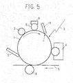
- FIG. 5 schematically shows the configuration of an image forming apparatus pertaining to embodiment 2 of the present invention comprising a mechanism for coating a lubricant onto an image carrier 1.
- a coating roller 8 is arranged on the image carrier 1 in a position between the area where a charging roller 2 is arranged and the area on which a laser beam 3 is irradiated.
- a solid lubricant 9 contacts the coating roller 8, the lubricant 9 is transferred to the coating roller 8 as a result of the rotation of the coating roller 8 and, thereafter, is coated from the coating roller 8 onto the image carrier 1.
- the lubricant coated on the image carrier 1 by the coating roller 8 is made uniform and level by a coating blade 10 arranged in contact with the image carrier 1 on the downstream side of the coating roller 8 in the direction of rotation of the image carrier 1.
- this lubricant zinc stearate is widely employed.
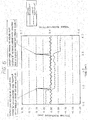
- a position fluctuation peak occurs at the point that the position of applied bias voltage "a” passes the cleaning blade 710 and, in addition, the torque fluctuation suddenly drops after the position of applied bias voltage "a” has passed the coating blade 10.
- irregularities in toner image density, or color displacement in the case of a color image forming apparatus are caused by position fluctuations.
- the position fluctuation and torque fluctuation are a temporary phenomenon and a stable state is immediately resumed.
- electrostatic latent image disturbance caused by fluctuations in speed of the image carrier can be prevented by initiating irradiation of exposure light of light scanning means, in other words, irradiating a laser beam 3 onto the image carrier 1 after the position of applied bias voltage "a" has passed the coating blade 10 and the position fluctuation and torque fluctuation have stabilized.
- a cleaning blade 7 is provided around the image carrier 1 and, accordingly, as shown in FIG. 6, because a position fluctuation peak also occurs at the point that the position of applied bias voltage "a” passes the cleaning blade 7 and, in addition, the torque fluctuation suddenly drops after the position of applied bias voltage "a” has passed the cleaning blade 7, irradiation of an exposure light of light scanning means is initiated after the position of applied bias voltage "a” has passed the cleaning blade 7 and the position fluctuation and torque fluctuation have stabilised, and because the position of the cleaning blade 7 is on the upstream side of the coating blade 10 in the direction of rotation of the image carrier 1, by satisfying the exposure initiation conditions described above for the coating blade 10, the exposure initiation conditions specific for the cleaning blade 7 can be simultaneously satisfied.
- the image forming method of example 1 described above is able to have application in image forming methods (apparatuses) that use an indirect transfer system in which the transfer member 5 described in FIG. 1 is a so-called intermediate transfer belt and, following the transfer of a toner image from the image carrier 1 onto the intermediate transfer belt, the toner image is retransferred to a sheet-like member serving as a final recording material.
- the image forming method of example 1 described above is able to have application in image forming methods (apparatuses) that use a direct transfer system in which the transfer member 5 described in FIG. 1 is a sheet-like medium that serves as a final recording material and the toner image of the image carrier 1 is transferred onto this sheet-like medium.
- image forming methods (apparatuses) described in example 1 to example 3 above are able to have application in image forming methods (apparatuses) that employ a plurality of image carriers and form color images by superposingly transferring the toner images of the image carriers onto a transfer material.
- the image forming method of the present invention described by example 3 is able to have application in an image forming apparatus of a configuration in which the coating roller 8 shown in the diagram is additionally provided around the image carriers of the tanderrt-type color image forming apparatus described by FIG. 3 that employs four (a plurality) of these image carriers.
- the image forming method of the present invention described by example 3 is able to have application in a configuration in which the coating roller 8 shown, in FIG. 5 is additionally provided around the photosensitive drum 30 of the process cartridge 200 described by FIG. 4.
- this embodiment can also have application in direct transfer systems, used in tandem-type color laser printers in which, as an example of example 1, toner images are directly transferred onto a sheet-like medium, or in monochrome laser printers that comprise a single toner image forming unit that employs a black toner.
- direct transfer systems used in tandem-type color laser printers in which, as an example of example 1, toner images are directly transferred onto a sheet-like medium, or in monochrome laser printers that comprise a single toner image forming unit that employs a black toner.
- copiers, printers and facsimile devices are examples of images that are directly transferred onto a sheet-like medium.
- electrostatic latent image disturbance caused by fluctuations in speed of the image carrier can be prevented by this invention by optical writing implemented after the position of applied bias voltage has passed the cleaning blade 7.
Landscapes
- Physics & Mathematics (AREA)
- General Physics & Mathematics (AREA)
- Engineering & Computer Science (AREA)
- Computer Vision & Pattern Recognition (AREA)
- Cleaning In Electrography (AREA)
- Electrostatic Charge, Transfer And Separation In Electrography (AREA)
- Exposure Or Original Feeding In Electrophotography (AREA)
- Control Or Security For Electrophotography (AREA)
- Color Electrophotography (AREA)
Abstract
Description
- The present invention relates to an image forming method and an image forming apparatus such as a copier, facsimile device, printer, plotter or combination printer using this image forming method.
- In conventionally known image forming methods an electrostatic latent image is formed as a result of exposure of an exposure light of light scanning means on an image carrier uniformly charged by charging means, visualizing of the electrostatic latent image as a toner image, transfer of the toner image to a transfer member by application of a bias voltage, and removal of toner remaining on the image carrier following transfer with a cleaning blade. In image forming methods of this kind, the surface electric potential state of the image carrier changes before and after the turning ON of this bias and, when this position (of changed surface electric potential) passes the blade, a load fluctuation that produces a fluctuation in speed of the image carrier is sometimes produced. When writing based on exposure scanning or the like is implemented in the course of a sudden position fluctuation and torque fluctuation of the image carrier, irregularities in toner image density, or color displacement in the case of a color image forming apparatus, are caused by position fluctuations.
- On the other hand, image forming belt apparatuses of a configuration, in which image forming process means are arranged around a belt spanning between at least two rollers and in which at least one process means acts on a the rollers imparting a rotation load fluctuation are known.
Japanese Unexamined Patent Application No. 2001-343843 - However, there is no reference made at all in.the technique disclosed in this application to the lowering of image quality of the transfer image that has its origin in the changes in the surface electric potential state of the image carrier that occur before and after the turning ON of the bias and the load fluctuations produced when this position (of changed surface electric potential state) passes the blade.
- It is an object of the present invention to provide an image forming method in which the lowering of image quality accompanying the application of a transfer bias voltage caused by the sudden load fluctuation that occurs when the position of applied bias on the image carrier passes a blade part in contact with the image carrier can be avoided, and an image forming apparatus in which this method is used.
- This object is solved by the subject-matter of the independent claims.
- In an aspect of the present invention, an image forming method comprises the steps of forming an electrostatic latent image by exposure with an exposure light of a light scanning device onto an image carrier charged by a charging device, visualizing the electrostatic latent image as a toner image, transferring the toner image to a transfer member by applying a bias voltage and removing toner remaining on said image carrier following transfer with a cleaning blade. Exposure by the light scanning device is initiated after the position on the image carrier where the application of the bias voltage has been initiated passes the cleaning blade.
- In another aspect of the present invention, an image forming apparatus uses an image forming method in which an electrostatic latent image is formed by exposure with an exposure light of a light scanning device onto an image carrier charged by a charging device, the electrostatic latent image is visualized as a toner image, the toner image is transferred to a transfer member by applying a bias voltage, remaining toner is removed from the image carrier following transfer with a cleaning blade, and exposure by said light scanning device is initiated after the position on the image carrier where the application of the bias voltage has been initiated has passes the cleaning blade. The plurality of image carriers are configured as process cartridges in each of which the charging device is integrated.
- In another aspect of the present invention, an image forming method comprises the steps of forming an electrostatic latent image by exposure with an exposure light of a light scanning device onto an image carrier charged by a charging device, visualizing the electrostatic latent image as a toner image, ransferring the toner image formed on the image carrier to a transfer member by applying a bias voltage and uniformly leveling a lubricant coated on the image carrier using a coating blade. Exposure by the light scanning device is initiated after the position on the image carrier where the application of the bias voltage has been initiated passes the cleaning blade.
- In another aspect of the present invention, an image forming apparatus uses an image forming method in which an electrostatic latent image is formed by exposure with an exposure light of a light scanning device onto an image carrier charged by a charging device, the electrostatic latent image is visualized as a toner image, the toner image formed on the image carrier is transferred to a transfer member by applying a bias voltage, a lubricant coated on the image carrier is uniformly leveled using a coating blade, and exposure by the light scanning means is initiated after the position on the image carrier where the application of the bias voltage has been initiated passes the cleaning blade. The plurality of image carrier are configured as process cartridges in each of which the charging device is integrated.
- The above and other objects, features and advantages of the present invention will become more apparent from the following detailed description based on the accompanying drawings in which:
- FIG. 1 is a schematic configuration diagram of an image forming apparatus pertaining to embodiment 1 of the present invention showing an image carrier and process members around the image carrier;
- FIG. 2 is a diagram for explaining torque fluctuations and position fluctuations of this image carrier;
- FIG. 3 is a schematic configuration diagram of a tandem-type color image forming apparatus pertaining to embodiment 1;
- FIG. 4 is a schematic configuration diagram of a process cartridge of this color image forming apparatus;
- FIG. 5 is a schematic configuration diagram of an image forming apparatus pertaining to a
embodiment 2 of the present invention showing an image carrier and process members around the image carrier; and - F1G. 6 is a diagram for explaining torque fluctuations and position fluctuations of this image carrier.
- Embodiments of the present invention will be hereinafter described in detail.
- FIG. 1 schematically shows the configuration of an image carrier and process members around the image carrier of an image forming apparatus pertaining to embodiment 1 of the present invention. As shown in the drawing, an image carrier 1 describes a drum shape that, while not shown in the diagram, is rotated in the clockwise direction by a drive motor. The image carrier 1 is charged by a
charging roller 2 serving as charging means and, while not shown in the diagram, an exposure light, in this example alaser beam 3, from a writing device serving as light scanning means comprising a laser light source is irradiated onto the image carrier 1 producing an electrostatic latent image. The electrostatic latent image is visualized as a toner image as a result of toner being adhered by adeveloper apparatus 4. Next, a transfer bias roller 6 for applying a bias voltage applies a bias and the toner image is transferred to atransfer member 5. Following this transfer, in preparation for subsequent image formation, acleaning blade 7 cleans all the toner remaining on the image carrier 1. - As shown in FIG. 1, taking the position of applied bias voltage on the image carrier 1 when application of the bias voltage on the transfer bias roller 6 is initiated (the instant the transfer bias is turned ON) as "a", after the position of applied bias voltage "a" moves accompanying the rotation of the image carrier 1 and passes position "b", in other words, the position at which the
cleaning blade 7 comes into contact therewith, an instantaneous decrease in load that causes a fluctuation in speed (position fluctuation) of the image carrier 1 is produced. FIG. 2 shows the details of the load fluctuation and position fluctuation that occur at this time. - As shown in FIG. 2, a position fluctuation peak occurs at the point that the position of applied bias voltage "a" passes the
cleaning blade 7 and, in addition, the torque fluctuation, suddenly drops after the position of applied bias voltage "a" has passed thecleaning blade 7. While in image forming apparatuses that implement the transfer of toner images in this way the transfer of the toner image to a transfer member normally involves application of bias to the toner image of an image carrier, a change in the surface electric potential state of the image carrier occurs before and after the turning ON of the bias and, when this position (of changed surface electric potential state) passes the blade it causes a fluctuation in speed of the image carrier. - When writing based on exposure scanning or the like is implemented in the course of a sudden position fluctuation and torque fluctuation of the image carrier 1, irregularities in toner image density, or color displacement in the case of a color image forming apparatus, are caused by position fluctuations. In addition, as shown in the diagram, the position fluctuation and torque fluctuation are a temporary phenomenon and a stable state is immediately resumed.
- Thereupon, using the image forming method (image forming control) of this embodiment of the present invention, electrostatic latent image disturbance caused by fluctuations in speed of the image carrier can be prevented by initiating irradiation of exposure light of light scanning means, in other words, irradiating a
laser beam 3 onto the image carrier 1 after the position of applied bias voltage "a" has passed thecleaning blade 7 and the position fluctuation and torque fluctuation have stabilized. - Naturally, the image forming method of example 1 described above is able to have application in image forming methods (apparatuses) that use an indirect transfer system in which the
transfer member 5 described in FIG. 1 is a so-called intermediate transfer belt and, after a toner image has been transferred from the image carrier 1 onto the intermediate transfer belt, the toner image is retransferred to a sheet-like member that serves as a final recording material. - Naturally, the image forming method of example 1 described above is able to have application in image forming methods (apparatuses) that use a direct transfer system in which the
transfer member 5 described in FIG. 1 is a sheet-like medium that serves as a final recording material and the toner image of the image carrier 1 is transferred onto this sheet-like medium. - Naturally, the image forming methods (apparatuses) described in example 1 to example 3 above are able to have application in image forming methods (apparatuses) that employ a plurality of image carriers and form color images by superposingly transferring the toner images of the image carriers onto a transfer material.
- The apparatus shown in FIG. 3 is a tandem-type color image forming apparatus in which the image forming method of example 1 described above has application. Four (a plurality) of image carriers around which processing members such as those shown in FIG. 1 are arranged are employed. FIG. 6 shows an expanded view of the schematic configuration of, of toner
image forming units 1Y (for yellow), 1M (for magenta), 1C (for cyan) and 1K (for black) that contain these image carriers, the tonerimage forming unit 1Y for yellow. The configuration of the other tonerimage forming units - As shown in FIG. 4, a
process cartridge 200 comprises aphotosensitive unit 200A and adeveloper unit 200B. Thephotosensitive unit 200A anddeveloper unit 200B may be formed as an integrated structure. Thephotosensitive unit 200A is configured to integrally Comprise at least acharging roller 70. - The surface of a
photosensitive drum 30 serving as the image carrier which is rotated in the clockwise direction is charged to a predetermined electric potential by thecharging roller 70 serving as charging means. Acleaning roller 70B for preventing soiling of the surface of thecharging roller 70 contacts thecharging roller 70 and is rotated to clean the surface thereof. - The
photosensitive drum 30 uniformly charged by thecharging roller 70 is exposed to a laser beam L serving as an exposure light from anoptical unit 40 serving as light scanning means shown in FIG. 3 forming an electrostatic latent image. Thedeveloper unit 200B for visualizing the electrostatic latent image comprises adevelopment roller 31 arranged so as to be partially exposed through an opening of adeveloper case 90A, carryingscrews toner density sensor 90E, and facilitates the supply of toner from atoner housing container 20Y shown in FIG. 3. A two-component developer (hereinafter referred to simply as the developer) containing a magnetic carrier and a minus-charge toner is contained in thedeveloper case 90A. - After being frictionally charged while agitatedly-carried by the carrying
screws development roller 31. After regulation of the layer thickness thereof by the development doctor 90D, the developer is carried to a position for development opposing thephotosensitive drum 30 where, as a result of the adhering of the toner to the electrostatic latent image on thephotosensitive drum 30, the electrostatic latent image is visualized. - In this way, a toner image of a predetermined color (yellow) is formed on the
photosensitive drum 30. The developer, the toner thereof having been used in the development process, is returned to thedeveloper case 90A accompanying the rotation of thedevelopment roller 31. The toner density of the developer in thedeveloper case 90A is detected by thetoner density sensor 90E and, in accordance with need, toner is supplied from thetoner housing container 20Y to a space above thescrew 90C. - Serving as a reference for attachment/detachment of the
process cartridge 200 to the image forming apparatusmain body 100 shown in FIG. 3, theprocess cartridge 200 comprises holes provided in a flange of the two end parts in the axial direction of thephotosensitive drum 30 that serve as main positioning reference parts, as well as auxiliary positioning reference parts not shown in the diagram provided in a frame in each of the front side and rear side thereof and, when thephotosensitive unit 200A is mounted in the apparatusmain body 100, thephotosensitive unit 200A is able to be reliably positioned in the predetermined position for mounting by means of linking parts provided between these reference parts and the apparatusmain body 100. - As shown in FIG. 3, the
photosensitive drum 30 contacts anintermediate transfer belt 400 of a transfer unit arranged there above to form a transfer nip that serves as the position for transfer. The toner developed on thephotosensitive drum 30 is transferred onto theintermediate transfer belt 400, while the non-transferred toner remaining on thephotosensitive drum 30 is removed by acleaning blade 11B and carried to a housing unit not shown in the drawing by atoner carry auger 11C. - Using a process identical to the process performed by the toner
image forming unit 1Y (for yellow), the other toner image forming units form single color toner images that are superposingly transferred in sequence onto the turning intermediate transfer belt. 400 for carrying the superposed toner image, the superposed toner image being then batch-transferred by asecondary transfer part 600 to a sheet-like medium supplied from apaper supply unit 500 before, by way of a fixing unit 700, being carried to adischarge paper tray 800. - While the description given above pertains to an indirect transfer system used in tandem-type color laser printer which serves as one example of example 2, this embodiment can also have application in direct transfer systems used in tandem-type color laser printers in which, as an example of example 3, toner images are directly transferred onto a sheet-like medium, or in monochrome laser printers that comprise a single toner image forming unit that employs a black toner. In addition, this embodiment is also able to have application in other image forming apparatuses such as copiers, printers and facsimile devices.
- FIG. 5 schematically shows the configuration of an image forming apparatus pertaining to
embodiment 2 of the present invention comprising a mechanism for coating a lubricant onto an image carrier 1. Acoating roller 8 is arranged on the image carrier 1 in a position between the area where a chargingroller 2 is arranged and the area on which alaser beam 3 is irradiated. A solid lubricant 9 contacts thecoating roller 8, the lubricant 9 is transferred to thecoating roller 8 as a result of the rotation of thecoating roller 8 and, thereafter, is coated from thecoating roller 8 onto the image carrier 1. The lubricant coated on the image carrier 1 by thecoating roller 8 is made uniform and level by acoating blade 10 arranged in contact with the image carrier 1 on the downstream side of thecoating roller 8 in the direction of rotation of the image carrier 1. In general, as this lubricant, zinc stearate is widely employed. - In the same way as for the
cleaning blade 7 described above, taking the position of applied bias voltage on the image carrier 1 when application of the bias voltage on the transfer bias roller 6 is initiated (the instant the transfer bias is turned ON) as "a", after the position of applied bias voltage all moves accompanying the rotation of the image carrier 1 and passes position "c" shown in the diagram, in other words, the position at which thecoating blade 10 comes into contact therewith, an instantaneous decrease in load that causes a fluctuation in speed (position fluctuation) of the image carrier 1 is produced. FIG. 6 shows the details of the load fluctuation and position fluctuation that occur at this time. - As shown in FIG. 6, a position fluctuation peak occurs at the point that the position of applied bias voltage "a" passes the cleaning blade 710 and, in addition, the torque fluctuation suddenly drops after the position of applied bias voltage "a" has passed the
coating blade 10. When writing based on exposure scanning or the like is implemented in the course of a sudden position fluctuation and torque fluctuation of the image carrier 1, irregularities in toner image density, or color displacement in the case of a color image forming apparatus, are caused by position fluctuations. In addition, as shown in the diagram, the position fluctuation and torque fluctuation are a temporary phenomenon and a stable state is immediately resumed. - Thereupon, using the image forming method (image forming control) of this embodiment of the present invention, electrostatic latent image disturbance caused by fluctuations in speed of the image carrier can be prevented by initiating irradiation of exposure light of light scanning means, in other words, irradiating a
laser beam 3 onto the image carrier 1 after the position of applied bias voltage "a" has passed thecoating blade 10 and the position fluctuation and torque fluctuation have stabilized. - In
embodiment 2, similarly to embodiment 1 shown in FIG. 5, acleaning blade 7 is provided around the image carrier 1 and, accordingly, as shown in FIG. 6, because a position fluctuation peak also occurs at the point that the position of applied bias voltage "a" passes thecleaning blade 7 and, in addition, the torque fluctuation suddenly drops after the position of applied bias voltage "a" has passed thecleaning blade 7, irradiation of an exposure light of light scanning means is initiated after the position of applied bias voltage "a" has passed thecleaning blade 7 and the position fluctuation and torque fluctuation have stabilised, and because the position of thecleaning blade 7 is on the upstream side of thecoating blade 10 in the direction of rotation of the image carrier 1, by satisfying the exposure initiation conditions described above for thecoating blade 10, the exposure initiation conditions specific for thecleaning blade 7 can be simultaneously satisfied. - Naturally, the image forming method of example 1 described above is able to have application in image forming methods (apparatuses) that use an indirect transfer system in which the
transfer member 5 described in FIG. 1 is a so-called intermediate transfer belt and, following the transfer of a toner image from the image carrier 1 onto the intermediate transfer belt, the toner image is retransferred to a sheet-like member serving as a final recording material. - Naturally, the image forming method of example 1 described above is able to have application in image forming methods (apparatuses) that use a direct transfer system in which the
transfer member 5 described in FIG. 1 is a sheet-like medium that serves as a final recording material and the toner image of the image carrier 1 is transferred onto this sheet-like medium. - Naturally, the image forming methods (apparatuses) described in example 1 to example 3 above are able to have application in image forming methods (apparatuses) that employ a plurality of image carriers and form color images by superposingly transferring the toner images of the image carriers onto a transfer material.
- The image forming method of the present invention described by example 3 is able to have application in an image forming apparatus of a configuration in which the
coating roller 8 shown in the diagram is additionally provided around the image carriers of the tanderrt-type color image forming apparatus described by FIG. 3 that employs four (a plurality) of these image carriers. - In addition, the image forming method of the present invention described by example 3 is able to have application in a configuration in which the
coating roller 8 shown, in FIG. 5 is additionally provided around thephotosensitive drum 30 of theprocess cartridge 200 described by FIG. 4. - Similarly, this embodiment can also have application in direct transfer systems, used in tandem-type color laser printers in which, as an example of example 1, toner images are directly transferred onto a sheet-like medium, or in monochrome laser printers that comprise a single toner image forming unit that employs a black toner. In addition, it is able to have application in other image forming apparatuses such as copiers, printers and facsimile devices.
- In
embodiments 1 and 2 of the present invention described above, electrostatic latent image disturbance caused by fluctuations in speed of the image carrier can be prevented by this invention by optical writing implemented after the position of applied bias voltage has passed thecleaning blade 7. - Various modifications will become possible for those skilled in the art after receiving the teachings of the present disclosure without departing from the scope thereof.
Claims (9)
- An image forming method comprising the steps of:forming an electrostatic latent image by exposure with an exposure light of light scanning means onto an image carrier charged by charging means;visualizing the electrostatic latent image as a toner image;transferring the toner image to a transfer member by applying a bias voltage; andpreparing said image carrier with a blade-like meanswherein exposure by said light scanning means is initiated after the position on said image carrier where the application of said bias voltage has been initiated passes said blade-like means.
- The image forming method as claimed in claim 1,
wherein the blade-like means is a cleaning means and the preparing step is for removing toner remaining on said image carrier following transfer with the cleaning blade. - The image forming method as claimed in claim 1,
wherein the blade-like means is a coating blade and the preparing step is for uniformly leveling a lubricant coated on said image carrier using the coating blade. - The image forming method as claimed in one of claims 1 to 3,
wherein an indirect transfer system in which a toner image is transferred onto said transfer member and the toner image is then retransferred onto a sheet-like medium is used. - The image forming method as claimed in one of claims 1 to 3,
wherein a direct transfer system in which a toner image is directly transferred onto said transfer member is used. - The image forming method as claimed in one of claims 1 to 3,
wherein a plurality of said image carriers are employed. - An image forming apparatus which uses an image forming method in which an electrostatic latent image is formed by exposure with an exposure light of light scanning means onto an image carrier charged by charging means, the electrostatic latent image is visualized as a toner image, the toner image in particular formed on the image carrier is transferred to a transfer member by applying a bias voltage,
wherein said image carrier is progressed following transfer with a blade-like device, and exposure by said light scanning means is initiated after the position on said image carrier where the application of said bias voltage has been initiated has passes said blade-like device,
wherein said plurality of image carriers are configured as process cartridges in each of which said charging means is integrated. - The image forming apparatus as claimed in claim 7,
wherein the blade-like device is a cleaning blade and by means of the cleaning blade remaining toner is removed from the image carrier. - The image forming apparatus as claimed in claim 7,
wherein the blade-like device is a coating blade and by means of the coating blade a lubricant coated on said image carrier is uniformly leveled.
Applications Claiming Priority (1)
| Application Number | Priority Date | Filing Date | Title |
|---|---|---|---|
| JP2005346441A JP4885526B2 (en) | 2005-11-30 | 2005-11-30 | Image forming apparatus |
Publications (2)
| Publication Number | Publication Date |
|---|---|
| EP1793286A1 true EP1793286A1 (en) | 2007-06-06 |
| EP1793286B1 EP1793286B1 (en) | 2015-08-12 |
Family
ID=37686150
Family Applications (1)
| Application Number | Title | Priority Date | Filing Date |
|---|---|---|---|
| EP06124492.7A Ceased EP1793286B1 (en) | 2005-11-30 | 2006-11-21 | Image forming method and image forming apparatus with a cleaning blade |
Country Status (4)
| Country | Link |
|---|---|
| US (1) | US20070122172A1 (en) |
| EP (1) | EP1793286B1 (en) |
| JP (1) | JP4885526B2 (en) |
| CN (1) | CN1996161A (en) |
Families Citing this family (6)
| Publication number | Priority date | Publication date | Assignee | Title |
|---|---|---|---|---|
| JP2010230906A (en) * | 2009-03-26 | 2010-10-14 | Seiko Epson Corp | Image forming apparatus and image forming method |
| JP2010281943A (en) * | 2009-06-03 | 2010-12-16 | Ricoh Co Ltd | Image forming apparatus |
| JP5472791B2 (en) * | 2009-08-24 | 2014-04-16 | 株式会社リコー | Image forming apparatus |
| JP5240579B2 (en) | 2009-09-07 | 2013-07-17 | 株式会社リコー | Image forming apparatus |
| JP6025445B2 (en) * | 2012-08-08 | 2016-11-16 | キヤノン株式会社 | Image forming apparatus |
| JP2024006421A (en) | 2022-07-01 | 2024-01-17 | 株式会社リコー | Image forming device, image forming method, and program |
Citations (5)
| Publication number | Priority date | Publication date | Assignee | Title |
|---|---|---|---|---|
| JPH02282776A (en) | 1989-04-25 | 1990-11-20 | Ricoh Co Ltd | Cleaning device and image forming device |
| EP0657784A1 (en) * | 1993-12-06 | 1995-06-14 | Xerox Corporation | Adaptive cleaner blade lubrication |
| JP2001343843A (en) | 2000-03-30 | 2001-12-14 | Ricoh Co Ltd | Belt device for image formation |
| JP2003186365A (en) | 2001-12-19 | 2003-07-04 | Hitachi Printing Solutions Ltd | Electrophotographic device and method for controlling the same |
| EP1431837A1 (en) | 2002-12-20 | 2004-06-23 | Ricoh Company, Ltd. | A colour image forming apparatus with installable process cartridges |
Family Cites Families (17)
| Publication number | Priority date | Publication date | Assignee | Title |
|---|---|---|---|---|
| JPH0750347B2 (en) * | 1985-12-24 | 1995-05-31 | コニカ株式会社 | Image forming device |
| US5051783A (en) * | 1989-07-29 | 1991-09-24 | Konica Corporation | Cam for shifting a transfer device and a cleaning device |
| US5220391A (en) * | 1990-07-16 | 1993-06-15 | Minolta Camera Kabushiki Kaisha | Image forming apporating having cleaning roller rotatable at different speeds during periods of image formation and non-image formation |
| JPH07128944A (en) * | 1993-11-05 | 1995-05-19 | Konica Corp | Color image forming device |
| JP3990760B2 (en) * | 1997-03-03 | 2007-10-17 | キヤノン株式会社 | Image forming apparatus |
| JP2001051549A (en) * | 1999-08-05 | 2001-02-23 | Ricoh Co Ltd | Image forming device |
| US6832058B2 (en) * | 2001-12-20 | 2004-12-14 | Konica Corporation | Image forming apparatus including a maximum charge quantity of toner particles forming useless toner |
| JP2003330320A (en) * | 2002-05-14 | 2003-11-19 | Konica Minolta Holdings Inc | Image forming device |
| US7092660B2 (en) * | 2003-05-26 | 2006-08-15 | Seiko Epson Corporation | Image forming apparatus |
| JP2005049717A (en) * | 2003-07-30 | 2005-02-24 | Kyocera Mita Corp | Image forming method |
| JP2005070276A (en) * | 2003-08-22 | 2005-03-17 | Ricoh Co Ltd | Image forming apparatus, process cartridge, and toner used therefor |
| JP2005084465A (en) * | 2003-09-10 | 2005-03-31 | Seiko Epson Corp | Image forming apparatus |
| JP2005202045A (en) * | 2004-01-14 | 2005-07-28 | Ricoh Co Ltd | Maintenance fee management system for image forming apparatus and maintenance fee management device used in the system |
| US7209699B2 (en) * | 2004-02-16 | 2007-04-24 | Ricoh Company, Limited | Lubricant applying unit, process cartridge, image forming apparatus, and image forming method |
| JP4621434B2 (en) * | 2004-03-25 | 2011-01-26 | 株式会社リコー | Image forming apparatus |
| JP2005326779A (en) * | 2004-05-17 | 2005-11-24 | Konica Minolta Business Technologies Inc | Image forming apparatus |
| US7206523B2 (en) * | 2004-09-13 | 2007-04-17 | Kabushiki Kaisha Toshiba | Color image forming apparatus and method using detachable process units |
-
2005
- 2005-11-30 JP JP2005346441A patent/JP4885526B2/en not_active Expired - Fee Related
-
2006
- 2006-11-17 US US11/561,085 patent/US20070122172A1/en not_active Abandoned
- 2006-11-21 EP EP06124492.7A patent/EP1793286B1/en not_active Ceased
- 2006-11-30 CN CNA2006100642348A patent/CN1996161A/en active Pending
Patent Citations (5)
| Publication number | Priority date | Publication date | Assignee | Title |
|---|---|---|---|---|
| JPH02282776A (en) | 1989-04-25 | 1990-11-20 | Ricoh Co Ltd | Cleaning device and image forming device |
| EP0657784A1 (en) * | 1993-12-06 | 1995-06-14 | Xerox Corporation | Adaptive cleaner blade lubrication |
| JP2001343843A (en) | 2000-03-30 | 2001-12-14 | Ricoh Co Ltd | Belt device for image formation |
| JP2003186365A (en) | 2001-12-19 | 2003-07-04 | Hitachi Printing Solutions Ltd | Electrophotographic device and method for controlling the same |
| EP1431837A1 (en) | 2002-12-20 | 2004-06-23 | Ricoh Company, Ltd. | A colour image forming apparatus with installable process cartridges |
Also Published As
| Publication number | Publication date |
|---|---|
| EP1793286B1 (en) | 2015-08-12 |
| CN1996161A (en) | 2007-07-11 |
| US20070122172A1 (en) | 2007-05-31 |
| JP4885526B2 (en) | 2012-02-29 |
| JP2007155779A (en) | 2007-06-21 |
Similar Documents
| Publication | Publication Date | Title |
|---|---|---|
| EP2639649A2 (en) | Developing apparatus | |
| JP2006267890A (en) | Image forming apparatus and belt unit | |
| US7877029B2 (en) | Image forming apparatus and fog control method | |
| US7177576B2 (en) | Apparatus for forming image using liquid development | |
| US7149459B2 (en) | Application roller and image forming apparatus | |
| EP1793286B1 (en) | Image forming method and image forming apparatus with a cleaning blade | |
| JP4385732B2 (en) | Image forming apparatus and method | |
| JP4277498B2 (en) | Image forming apparatus | |
| JP4349898B2 (en) | Developing device in image forming apparatus and method of operating developing device | |
| JP4669275B2 (en) | Image forming apparatus | |
| JP4470439B2 (en) | Image forming apparatus | |
| JPH09160375A (en) | Developing device | |
| JP2010032832A (en) | Rotation control method and image forming apparatus | |
| JP4269617B2 (en) | Image forming apparatus | |
| CN108508720B (en) | Image forming apparatus with a toner supply device | |
| CN121657402A (en) | Image forming apparatus having a plurality of image forming units | |
| US20070104514A1 (en) | Image forming method and printing method thereof | |
| JP2003241515A (en) | Image forming device | |
| JP2002169369A (en) | Image forming device | |
| JP2000172043A (en) | Color image forming device | |
| JP4610995B2 (en) | Developing device using one-component developer, image forming apparatus, and process cartridge | |
| JP6880622B2 (en) | Developing equipment and image forming equipment | |
| JP2023075866A (en) | image forming device | |
| JP5187175B2 (en) | Lubricant coating apparatus and image forming apparatus | |
| JP2022032390A (en) | Developing device and image forming apparatus including the same |
Legal Events
| Date | Code | Title | Description |
|---|---|---|---|
| PUAI | Public reference made under article 153(3) epc to a published international application that has entered the european phase |
Free format text: ORIGINAL CODE: 0009012 |
|
| 17P | Request for examination filed |
Effective date: 20061121 |
|
| AK | Designated contracting states |
Kind code of ref document: A1 Designated state(s): AT BE BG CH CY CZ DE DK EE ES FI FR GB GR HU IE IS IT LI LT LU LV MC NL PL PT RO SE SI SK TR |
|
| AX | Request for extension of the european patent |
Extension state: AL BA HR MK YU |
|
| AKX | Designation fees paid |
Designated state(s): DE FR GB |
|
| 17Q | First examination report despatched |
Effective date: 20111222 |
|
| GRAP | Despatch of communication of intention to grant a patent |
Free format text: ORIGINAL CODE: EPIDOSNIGR1 |
|
| INTG | Intention to grant announced |
Effective date: 20150428 |
|
| GRAS | Grant fee paid |
Free format text: ORIGINAL CODE: EPIDOSNIGR3 |
|
| GRAA | (expected) grant |
Free format text: ORIGINAL CODE: 0009210 |
|
| AK | Designated contracting states |
Kind code of ref document: B1 Designated state(s): DE FR GB |
|
| REG | Reference to a national code |
Ref country code: GB Ref legal event code: FG4D |
|
| REG | Reference to a national code |
Ref country code: DE Ref legal event code: R096 Ref document number: 602006046236 Country of ref document: DE |
|
| REG | Reference to a national code |
Ref country code: FR Ref legal event code: PLFP Year of fee payment: 10 |
|
| REG | Reference to a national code |
Ref country code: DE Ref legal event code: R097 Ref document number: 602006046236 Country of ref document: DE |
|
| PLBE | No opposition filed within time limit |
Free format text: ORIGINAL CODE: 0009261 |
|
| STAA | Information on the status of an ep patent application or granted ep patent |
Free format text: STATUS: NO OPPOSITION FILED WITHIN TIME LIMIT |
|
| 26N | No opposition filed |
Effective date: 20160513 |
|
| REG | Reference to a national code |
Ref country code: FR Ref legal event code: PLFP Year of fee payment: 11 |
|
| REG | Reference to a national code |
Ref country code: FR Ref legal event code: PLFP Year of fee payment: 12 |
|
| PGFP | Annual fee paid to national office [announced via postgrant information from national office to epo] |
Ref country code: FR Payment date: 20171121 Year of fee payment: 12 Ref country code: DE Payment date: 20171121 Year of fee payment: 12 |
|
| PGFP | Annual fee paid to national office [announced via postgrant information from national office to epo] |
Ref country code: GB Payment date: 20171123 Year of fee payment: 12 |
|
| REG | Reference to a national code |
Ref country code: DE Ref legal event code: R119 Ref document number: 602006046236 Country of ref document: DE |
|
| GBPC | Gb: european patent ceased through non-payment of renewal fee |
Effective date: 20181121 |
|
| PG25 | Lapsed in a contracting state [announced via postgrant information from national office to epo] |
Ref country code: FR Free format text: LAPSE BECAUSE OF NON-PAYMENT OF DUE FEES Effective date: 20181130 Ref country code: DE Free format text: LAPSE BECAUSE OF NON-PAYMENT OF DUE FEES Effective date: 20190601 |
|
| PG25 | Lapsed in a contracting state [announced via postgrant information from national office to epo] |
Ref country code: GB Free format text: LAPSE BECAUSE OF NON-PAYMENT OF DUE FEES Effective date: 20181121 |