EP1793152B1 - Fluidkupplungsanordnung mit elektrischer Steckverbinderanordnung - Google Patents
Fluidkupplungsanordnung mit elektrischer Steckverbinderanordnung Download PDFInfo
- Publication number
- EP1793152B1 EP1793152B1 EP06024817A EP06024817A EP1793152B1 EP 1793152 B1 EP1793152 B1 EP 1793152B1 EP 06024817 A EP06024817 A EP 06024817A EP 06024817 A EP06024817 A EP 06024817A EP 1793152 B1 EP1793152 B1 EP 1793152B1
- Authority
- EP
- European Patent Office
- Prior art keywords
- fluid
- coupling
- electrical
- coupling arrangement
- coupling part
- Prior art date
- Legal status (The legal status is an assumption and is not a legal conclusion. Google has not performed a legal analysis and makes no representation as to the accuracy of the status listed.)
- Revoked
Links
Images


Classifications
-
- H—ELECTRICITY
- H01—ELECTRIC ELEMENTS
- H01R—ELECTRICALLY-CONDUCTIVE CONNECTIONS; STRUCTURAL ASSOCIATIONS OF A PLURALITY OF MUTUALLY-INSULATED ELECTRICAL CONNECTING ELEMENTS; COUPLING DEVICES; CURRENT COLLECTORS
- H01R13/00—Details of coupling devices of the kinds covered by groups H01R12/70 or H01R24/00 - H01R33/00
- H01R13/005—Electrical coupling combined with fluidic coupling
-
- F—MECHANICAL ENGINEERING; LIGHTING; HEATING; WEAPONS; BLASTING
- F16—ENGINEERING ELEMENTS AND UNITS; GENERAL MEASURES FOR PRODUCING AND MAINTAINING EFFECTIVE FUNCTIONING OF MACHINES OR INSTALLATIONS; THERMAL INSULATION IN GENERAL
- F16L—PIPES; JOINTS OR FITTINGS FOR PIPES; SUPPORTS FOR PIPES, CABLES OR PROTECTIVE TUBING; MEANS FOR THERMAL INSULATION IN GENERAL
- F16L25/00—Constructive types of pipe joints not provided for in groups F16L13/00 - F16L23/00 ; Details of pipe joints not otherwise provided for, e.g. electrically conducting or insulating means
- F16L25/01—Constructive types of pipe joints not provided for in groups F16L13/00 - F16L23/00 ; Details of pipe joints not otherwise provided for, e.g. electrically conducting or insulating means specially adapted for realising electrical conduction between the two pipe ends of the joint or between parts thereof
-
- F—MECHANICAL ENGINEERING; LIGHTING; HEATING; WEAPONS; BLASTING
- F16—ENGINEERING ELEMENTS AND UNITS; GENERAL MEASURES FOR PRODUCING AND MAINTAINING EFFECTIVE FUNCTIONING OF MACHINES OR INSTALLATIONS; THERMAL INSULATION IN GENERAL
- F16L—PIPES; JOINTS OR FITTINGS FOR PIPES; SUPPORTS FOR PIPES, CABLES OR PROTECTIVE TUBING; MEANS FOR THERMAL INSULATION IN GENERAL
- F16L53/00—Heating of pipes or pipe systems; Cooling of pipes or pipe systems
- F16L53/30—Heating of pipes or pipe systems
- F16L53/35—Ohmic-resistance heating
- F16L53/38—Ohmic-resistance heating using elongate electric heating elements, e.g. wires or ribbons
-
- F—MECHANICAL ENGINEERING; LIGHTING; HEATING; WEAPONS; BLASTING
- F01—MACHINES OR ENGINES IN GENERAL; ENGINE PLANTS IN GENERAL; STEAM ENGINES
- F01N—GAS-FLOW SILENCERS OR EXHAUST APPARATUS FOR MACHINES OR ENGINES IN GENERAL; GAS-FLOW SILENCERS OR EXHAUST APPARATUS FOR INTERNAL COMBUSTION ENGINES
- F01N2610/00—Adding substances to exhaust gases
- F01N2610/02—Adding substances to exhaust gases the substance being ammonia or urea
-
- F—MECHANICAL ENGINEERING; LIGHTING; HEATING; WEAPONS; BLASTING
- F01—MACHINES OR ENGINES IN GENERAL; ENGINE PLANTS IN GENERAL; STEAM ENGINES
- F01N—GAS-FLOW SILENCERS OR EXHAUST APPARATUS FOR MACHINES OR ENGINES IN GENERAL; GAS-FLOW SILENCERS OR EXHAUST APPARATUS FOR INTERNAL COMBUSTION ENGINES
- F01N2610/00—Adding substances to exhaust gases
- F01N2610/10—Adding substances to exhaust gases the substance being heated, e.g. by heating tank or supply line of the added substance
-
- F—MECHANICAL ENGINEERING; LIGHTING; HEATING; WEAPONS; BLASTING
- F01—MACHINES OR ENGINES IN GENERAL; ENGINE PLANTS IN GENERAL; STEAM ENGINES
- F01N—GAS-FLOW SILENCERS OR EXHAUST APPARATUS FOR MACHINES OR ENGINES IN GENERAL; GAS-FLOW SILENCERS OR EXHAUST APPARATUS FOR INTERNAL COMBUSTION ENGINES
- F01N2610/00—Adding substances to exhaust gases
- F01N2610/14—Arrangements for the supply of substances, e.g. conduits
-
- H—ELECTRICITY
- H01—ELECTRIC ELEMENTS
- H01R—ELECTRICALLY-CONDUCTIVE CONNECTIONS; STRUCTURAL ASSOCIATIONS OF A PLURALITY OF MUTUALLY-INSULATED ELECTRICAL CONNECTING ELEMENTS; COUPLING DEVICES; CURRENT COLLECTORS
- H01R13/00—Details of coupling devices of the kinds covered by groups H01R12/70 or H01R24/00 - H01R33/00
- H01R13/62—Means for facilitating engagement or disengagement of coupling parts or for holding them in engagement
- H01R13/627—Snap or like fastening
- H01R13/6275—Latching arms not integral with the housing
Definitions
- the present invention relates to a fluid coupling assembly having at least a first coupling part for connecting a first fluid conducting element such as a fluid line and at least one second fluid carrying element in cooperation with at least one second coupling part, wherein a fluid between the first fluid carrying element and the at least one second fluid-carrying element flows through the fluid coupling assembly.
- the invention further relates to a fluid distribution system in a motor vehicle that uses a fluid coupling assembly according to the present invention.
- the US 4,550,958 refers to a rotatable connector for connecting a vacuum cleaner hose to the vacuum cleaner housing.
- the vacuum cleaner hose is wound with an electrical line, which serves for the electrical supply of an electrically operated brush. Therefore, the rotatable connector has a connector for contacting this line and is provided with corresponding mating contacts of the housing, which are connected to slip rings on the housing neck.
- the US 2002/058436 A1 refers to a connector for connecting hoses and pipes on the one hand and electrical lines on the other.
- the electrical line is but in no immediate connection with the hose, but is only performed parallel to this.
- the lines are not for heating the hoses are suitable, but serve to monitor whether the fluidic connections are properly closed.
- the US 6,030,244 discloses a connector system, on the one hand mechanically connects hose lines together and on the other hand has electrical connectors for contacting electrical lines.
- the electrical lines are routed parallel to the hose lines to be carried in parallel with the hose, for example in an electrically controlled pneumatic brake system, but do not serve the heating of the hose.
- the WO 97/34339 A refers to a connector system for connecting hose lines, in which electrical contacts are plugged together when closing the mechanical connection.
- the parallel to the hose lines extending electrical conductors serve a power or signal supply.
- the GB 2 056 611 A refers to a connector for connecting a vacuum cleaner hose, with the same time an electrical connection between a guided along the hose along the cable on the one hand and the motor housing on the other hand is made.
- a coupling piece is proposed, which is used to connect the hose to the motor housing.
- this document does not disclose the provision of a heating wire and in no way a rotatable electrical contact.
- the US 5,791,377 discloses an electrically heated hose line, for example for directing wiper water to a windshield wiper nozzle.
- the hose line disclosed in this document shows heating wires for heating the hose, these wires are not electrically contacted by means of a connector, but via slidable contact elements provided inside the end piece.
- an electrical connector and a fluidic coupling which establish a connection between a heatable hose and a hot glue gun.
- a plurality of electrical conductors are included in the sheath of the tube, the ends of which are provided with crimp terminals.
- An electrical connector 24 receives these crimp terminals and allows electrical connection to another electrical connector 25 which contacts the hot melt gun via a loose electrical lead.
- the object on which the present invention is based is to disclose a fluid coupling arrangement and a corresponding fluid distribution system which fluidly as well as electrically connects elements of a fluid conveyor chain in the simplest and safest way and allows safe fluid flow under all operating conditions.
- the present invention is based on the basic idea that the fluid coupling arrangement has at least one electrical connector arrangement for connecting at least one first electrical line to at least one second electrical line.
- the clutch assembly according to the invention is a stable and robust solution even under the thermally and mechanically demanding environmental conditions in the automotive field.
- Another advantage of the solution according to the invention is that each power consumer each correct supply voltage can be provided.
- the first coupling part and a connector of the at least one connector assembly are accommodated in a first electrically insulating housing.
- a first electrically insulating housing Such an integrated solution makes it possible, for example, for heated hoses to be provided with prefabricated combined electrical and fluidic connections.
- the second coupling part and an associated mating connector of the at least one connector assembly are received in a second electrically insulating housing and that the first and second housing are plugged together to make the fluidic and the electrical connection, then the contacting of both fluidic as well as electrical Components in one step feasible.
- a holding device for mechanically securing the two coupling parts together in the assembled state can be provided.
- this holding device may be formed by at least one latching arm, which is arranged on one of the two coupling parts and can be latched with a latching projection arranged on the other coupling part.
- this holding device may be formed by at least one latching arm, which is arranged on one of the two coupling parts and can be latched with a latching projection arranged on the other coupling part.
- other known holding and locking devices such as a screw and the like for securing the two coupling parts can be used together.
- the first coupling part may also be designed, for example, as a fitting in the form of a through-coupling piece (I-piece), an elbow (L-piece) or a branch piece, which is also referred to as a T-piece. be executed.
- branches are possible for more than three connections.
- the fluid distribution system is simplified significantly, if the required distribution and power transmission need not be carried out in the form of loose wiring outside the fluid system, but is realized as an integrated clutch arrangement.
- a hose connection element for the first fluid line is formed on the first coupling part, which electrically contacts an electrical line arranged on the first fluid line and connects to the connector of the at least one connector arrangement.
- a heating wire of an electrically heated hose is contacted via the electrical connector of the fluid coupling arrangement according to the invention.
- the first coupling part can be rotatably arranged on the first fluid line and the at least one first electrical line can have an axially revolving around the fluid line slip ring of contact elements of a Connector is contacted at least one connector assembly. In this way it can also be prevented that the electrical contact is interrupted by mechanical stress of the contacting of the electrical line during installation or operation of the motor vehicle.
- the first coupling part and / or the second coupling part can be made electrically heated. In this way it can be ensured that the entire fluid distribution system remains ice-free.
- Fig. 1 shows a fluid distribution system 100, as can be used in a motor vehicle, in a schematic representation.
- heatable components 102, 104 are supplied or flowed through fluid lines 106 with a fluid.
- the fluid can be either a liquid or a gas, for example water for windscreen cleaning or an aqueous urea solution, as used to reduce the nitrogen oxides in the SCR process.
- SCR Selective Catalytic Reduction
- SCR Selective Catalytic Reduction
- a reducing agent As a reducing agent, steam or gaseous ammonia is often used, which is generated by evaporation, subsequent thermolysis and hydrolysis of urea or a urea solution and introduced into the exhaust gas stream. Such a urea solution must then be transported along in appropriate tanks via the fluid conveyor chain and fed to the catalyst as a consumer. Furthermore, as a fluid, a gas, such as the blow-by gas in an internal combustion engine, are considered.
- the fluid lines 106 are electrically heated. , The connections of this electrical heating are symbolized by the electrical lines 108. As in Fig. 1 schematically illustrated, the connection between two heated fluid lines via a configured as a passage connector fluid coupling assembly 110 takes place.
- the fluid coupling arrangement 110 has a first coupling part 112 and a second coupling part 114. These two coupling parts cooperate to connect a first fluid line 116 to a second fluid line 118. Between the two fluid lines, the fluid flows in the connected state. Furthermore, the fluid coupling assembly 110 has an electrical connector assembly 120, by means of which the electrical leads 122, 124 and 126, 128 can be interconnected. An energy source 130 supplies the assembly with electrical energy needed, for example, to heat the tubes. In this case, the battery 130 shown can only be seen as an exemplary solution. The power supply can also be provided with suitable switching elements and fuses or be controlled by the engine electronics.
- Fig. 2 shows in a perspective view of the fluid coupling assembly 110 from Fig. 1 according to a possible embodiment.
- two fluid line pieces 116, 118 which are connected to each other via the fluid coupling assembly 110 according to a first embodiment, and a first coupling part 112 which is ready to be connected to either a further line piece or for example to the connection of a pump.
- an electrical connector arrangement 120 consisting of a plug connector 132 and a mating connector 134, is additionally provided on the fluid coupling arrangement 110 in order to be able to establish an electrical connection simultaneously with the fluidic coupling.
- Both the connector 132 and the mating connector 134 are connected to electrical lines inside the respective first and second coupling parts 112, 114, which are guided along the fluid lines 116, 118 (not shown in the figure).
- Two latching arms 136 which are integrally formed on the coupling part 112, cooperate with a latching projection 138, which is provided on the coupling part 114.
- the first coupling part 112 associated connector 132 is provided with connector pins 140, and the mating connector 134 is designed accordingly as a female connector.
- the mating connector 134 is designed accordingly as a female connector.
- any number and configuration of connector pins can be used in the connector 120.
- Common sealing devices 142 are disposed on the first coupling part 112 to prevent leakage of the fluid to the fluid coupling assembly 110. Furthermore, of course, the connector 120 may be sealed by professional measures against ingress of moisture.
- latching arms 136 have actuators 144, by means of which the latching connection can be easily solved when the fluid coupling is to be separated.
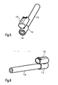
- FIGS. 3 and 4 Another embodiment of a first coupling part 112, as mounted on a fluid line 116, is shown in FIGS FIGS. 3 and 4 shown.
- the latching device is here on the connector 132.
- the associated latching arm and the connector 134 are not shown.
- This embodiment has the advantage that, in particular, the vibration-sensitive electrical connection is secured, while the firmly pressed fluid connection remains fixed in the axial direction without additional securing.
- a further advantageous embodiment of a first coupling part 112 is explained with a molded-on connector 132 thereon.
- the plug face of the connector 132 from the fluid entry port 146 turned away.
- This solution has the advantage that an electrical heating device integrated in the hose 116 can be connected to the plug connector 132 and can be electrically contacted by means of a loose mating plug connector 134, not shown here.
- the plug pins 140 are electrically connected to the slip rings 148, 150 via resilient contacts 154. Seals 156, 158 prevent the ingress of moisture into the electrical connector.
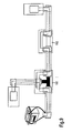
- FIG. 8 A further advantageous embodiment of the fluid coupling arrangement 110 according to the invention is shown in FIG. 8 shown.
- the power supply is located at one end of the fluid distribution system.
- the connector 120 may additionally have a supply plug 121 for connecting a supply voltage.
- a fluid distribution system for use in a motor vehicle may require the most diverse forms of a fluid coupling arrangement.
- a first coupling part can be provided, which realizes the shape of a T-piece and which in each case is contacted fluidically and electrically in accordance with the principles according to the invention.
- One such branch piece or tee is in Fig. 9 provided with the reference numeral 160.
- any other type of fittings can be realized using the principles of the invention: for example, a through-coupling piece (I-piece) 162 or an elbow (L-piece), which is not shown here.
- a T-shaped branching of the branching piece 160 instead of the T-shaped branching of the branching piece 160, a Y-shaped channel structure may also be provided.
- branches for more than three connections are possible.
- the individual elements of the fluid coupling assembly may be made heatable to prevent ice accumulation throughout the fluid distribution system.
Description
- Die vorliegende Erfindung bezieht sich auf eine Fluidkupplungsanordnung, die mindestens ein erstes Kupplungsteil zum Verbinden einem ersten fluidführenden Element wie einer Fluidleitung und mindestens einem zweiten fluidführenden Element im Zusammenwirken mit mindestens einem zweiten Kupplungsteil aufweist, wobei ein Fluid zwischen dem ersten fluidführenden Element und dem mindestens einen zweiten fluidführenden Element durch die Fluidkupplungsanordnung strömt.
- Die Erfindung bezieht sich weiterhin auf ein Fluidverteilungssystem in einem Kraftfahrzeug, das eine Fluidkupplungsanordnung gemäß der vorliegenden Erfindung verwendet.
- In modernen Kraftfahrzeugen werden die vielfältigsten Fluide gefördert und verteilt, wie beispielsweise Reinigungsflüssigkeiten für die Scheiben- oder Scheinwerferreinigung, wässerige Hamstofflösungen im Zusammenhang mit der sogenannten SCR-Technologie (selective catalytic reduction), Kraftstoffe, aber auch Blowbygase. In der Förderkette dieser Fluide kann bei niedrigen Temperaturen die in der Förderkette enthaltene Flüssigkeit bzw. die in dem Gas enthaltene Feuchtigkeit einfrieren und es können Eisansätze vorkommen. Deshalb werden bei bekannten Anordnungen, die diese Fluide fördern, fluidführende Elemente der Förderkette, wie z. B. Pumpen oder Schläuche, beheizt, um das Einfrieren derselben zu verhindern.
- In der Regel werden für eine solche Beheizung elektrische Heizvorrichtungen verwendet und es besteht das Problem, dass eine umfangreiche Verkabelung und aufwendige Verbindungstechnik insbesondere an den Schnittstellen zwischen einzelnen Fluidleitungen oder zwischen einer Fluidleitung und einer weiteren Komponente der Förderkette, wie einer Pumpe oder dergleichen, erforderlich sind.
- Die
US 4,550,958 bezieht sich auf ein drehbares Verbindungsstück zum Verbinden eines Staubsaugerschlauchs mit dem Staubsaugergehäuse. Der Staubsaugerschlauch ist mit einer elektrischen Leitung umwunden, welche zur elektrischen Versorgung einer elektrisch betriebenen Bürste dient. Daher weist das drehbare Verbindungsstück einen Steckverbinder zum Kontaktieren dieser Leitung auf und ist mit entsprechenden Gegenkontakten des Gehäuses versehen, die mit Schleifringen an dem Gehäusestutzen verbunden sind. - Die
US 2002/058436 A1 bezieht sich auf einen Verbinder zum Verbinden von Schläuchen und Rohrleitungen einerseits und elektrischen Leitungen andererseits. Die elektrische Leitung steht aber in keinem unmittelbaren Zusammenhang mit dem Schlauch, sondern wird lediglich parallel zu diesem geführt. Insbesondere sind die Leitungen nicht zum Beheizen der Schläuche geeignet, sondern dienen der Überwachung, ob die fluidischen Verbindungen ordnungsgemäß geschlossen sind. - Die
US 6,030,244 offenbart ein Verbindersystem, das einerseits Schlauchleitungen mechanisch miteinander verbindet und andererseits elektrische Steckverbindungen zum Kontaktieren von elektrischen Leitungen aufweist. Dabei sind die elektrischen Leitungen parallel zu den Schlauchleitungen geführt, um beispielsweise bei einem elektrisch gesteuerten pneumatischen Bremsensystem parallel mit dem Schlauch mitgeführt zu werden, dienen aber nicht der Beheizung des Schlauchs. - Die
WO 97/34339 A - Die
GB 2 056 611 A - Die
US 5,791 377 offenbart eine elektrisch beheizte Schlauchleitung, beispielsweise zum Leiten von Wischwasser an eine Scheibenwischerdüse. Zwar zeigt die in dieser Druckschrift offenbarte Schlauchleitung Heizdrähte zum Beheizen des Schlauchs, aber diese Drähte werden nicht mit Hilfe eines Steckverbinders elektrisch kontaktiert, sondern über aufgeschobene Kontaktelemente, die im Inneren des Endstücks vorgesehen sind. - Aus der
EP 0187943 A2 ist ein elektrischer Verbinder sowie eine fluidische Kupplung bekannt, die eine Verbindung zwischen einem beheizbaren Schlauch und einer Heißkleberpistole herstellen. Wie aus denFiguren 1 bis 3 und der zugehörigen Beschreibung ersichtlich, ist in der Hülle des Schlauchs eine Vielzahl von elektrischen Leitern enthalten, deren Enden mit Crimpanschlüssen versehen sind. Ein elektrischer Verbinder 24 nimmt diese Crimpanschlüsse auf und ermöglicht eine elektrische Verbindung zu einem weiteren elektrischen Steckverbinder 25, der über eine lose elektrische Leitung die Heißkleberpistole kontaktiert. Der fluidische Anschluss zwischen der Heißkleberpistole und dem beheizbaren Heißkleberschlauch erfolgt über eine konventionelle geschraubte Schlauchkupplung unabhängig von der elektrischen Steckverbindung. - Die Aufgabe, die der vorliegenden Erfindung zugrunde liegt, besteht darin, eine Fluidkupplungsanordnung und ein entsprechendes Fluidverteilungssystem anzugeben, das auf möglichst einfache und sichere Weise Elemente einer Fluidförderkette fluidisch wie auch elektrisch miteinander verbindet und einen sicheren Fluidfluss bei allen Betriebsbedingungen erlaubt.
- Diese Aufgabe wird durch den Gegenstand der unabhängigen Patentansprüche gelöst. Vorteilhafte Weiterbildungen der vorliegenden Erfindung sind Gegenstand mehrerer Unteransprüche.
- Dabei basiert die vorliegende Erfindung auf der Grundidee, dass die Fluidkupplungsanordnung mindestens eine elektrische Steckverbinderanordnung zum Verbinden mindestens einer ersten elektrischen Leitung mit mindestens einer zweiten elektrischen Leitung aufweist.
- Auf diese Weise kann, beispielsweise beim Zusammenschließen von beheizbaren Schläuchen, erreicht werden, dass diese kombinierte fluidische und elektrische Verbindung auf eine besonders einfache Art und Weise montiert werden und auf zusätzliche Kabelbäume verzichtet werden kann. Weiterhin stellt die erfindungsgemäße Kupplungsanordnung auch unter den thermisch und mechanisch stark beanspruchenden Umgebungsbedingungen im Kraftfahrzeugbereich eine stabile und robuste Lösung dar.
- Ein weiterer Vorteil der erfindungsgemäßen Lösung besteht darin, dass jedem Stromverbraucher die jeweils richtige Versorgungsspannung bereitgestellt werden kann.
- Gemäß einer vorteilhaften Ausführungsform sind das erste Kupplungsteil und ein Steckverbinder der mindestens einen Steckverbinderanordnung in einem ersten elektrisch isolierenden Gehäuse aufgenommen. Eine solche integrierte Lösung ermöglicht es, dass beispielsweise beheizbare Schläuche mit vorkonfektionierten kombinierten elektrischen und fluidischen Anschlüssen versehen werden können.
- Sieht man weiterhin vor, dass das zweite Kupplungsteil und ein zugehöriger Gegensteckverbinder der mindestens einen Steckverbinderanordnung in einem zweiten elektrisch isolierenden Gehäuse aufgenommen sind und dass das erste und zweite Gehäuse zusammensteckbar sind, um die fluidische und die elektrische Verbindung herzustellen, so ist die Kontaktierung sowohl der fluidischen wie auch der elektrischen Komponenten in einem Arbeitsschritt durchführbar. Damit sich die einmal geschlossene Verbindung nicht wieder unbeabsichtigt löst, kann gemäß einer vorteilhaften Ausführungsform eine Haltevorrichtung zum mechanischen Sichern der beiden Kupplungsteile aneinander in dem zusammengesteckten Zustand vorgesehen werden.
- Insbesondere kann diese Haltevorrichtung durch mindestens einen Rastarm gebildet sein, der an einem der beiden Kupplungsteile angeordnet ist und mit einem an dem anderen Kupplungsteil angeordneten Rastvorsprung verrastbar ist. Selbstverständlich können aber auch andere bekannte Halte- und Verriegelungsvorrichtungen, wie beispielsweise eine Verschraubung und dergleichen zum Sichern der beiden Kupplungsteile aneinander verwendet werden.
- Je nachdem, an welcher Stelle und für welchen Zweck die erfindungsgemäße Fluidkupplungsanordnung in einem Fluidverteilungssystem eingesetzt werden soll, ergeben sich verschiedene mögliche Formen für das erste Kupplungsteil. So kann das erste Kupplungsteil neben der Ausgestaltung als einfacher Verbinder mit einem zweiten Verbinder beispielsweise auch als ein Fitting in Form eines Durchgangskupplungsstücks (I-Stück), eines Winkelstücks (L-Stück) oder eines Abzweigstücks, das auch als T-Stück bezeichnet wird, ausgeführt sein. Weiterhin sind Verzweigungen für mehr als drei Anschlüsse möglich. Insbesondere im Fall des Abzweigstücks vereinfacht sich das Fluidverteilungssystem signifikant, wenn die benötigte Verteilung und Stromdurchleitung nicht in Form von loser Verkabelung außerhalb des Fluidsystems durchgeführt werden muss, sondern als integrierte Kupplungsanordnung realisiert ist.
- Gemäß einer vorteilhaften Weiterbildung der vorliegenden Erfindung ist an dem ersten Kupplungsteil ein Schlauchanschlusselement für die erste Fluidleitung ausgebildet, das eine an der ersten Fluidleitung angeordnete elektrische Leitung elektrisch kontaktiert und mit dem Steckverbinder der mindestens einen Steckverbinderanordnung verbindet. Auf diese Weise ist ein Heizdraht eines elektrisch beheizten Schlauchs über den elektrischen Steckverbinder der erfindungsgemäßen Fluidkupplungsanordnung kontaktiert.
- Um von Fertigungstoleranzen unabhängig zu werden und flexibel auf verschiedenste geometrische Einbaulagen im Kraftfahrzeug reagieren zu können, kann das erste Kupplungsteil drehbar an der ersten Fluidleitung angeordnet sein und die mindestens eine erste elektrische Leitung kann einen axial um die Fluidleitung umlaufenden Schleifring aufweisen, der von Kontaktelementen eines Steckverbinders der mindestens einen Steckverbinderanordnung kontaktiert ist. Auf diese Weise kann auch verhindert werden, dass durch mechanische Beanspruchung der Kontaktierung der elektrischen Leitung beim Einbau oder Betrieb des Kraftfahrzeugs der elektrische Kontakt unterbrochen wird.
- Um zu verhindern, dass zwar die Schlauchleitungen eisfrei sind, aber bei niedrigen Temperaturen Eisansätze in der Fluidkupplungsanordnung auftreten, kann gemäß einer vorteilhaften Weiterbildung das erste Kupplungsteil und/oder das zweite Kupplungsteil elektrisch beheizbar ausgeführt sein. Auf diese Weise kann sichergestellt werden, dass das gesamte Fluidverteilungssystem eisfrei bleibt.
- Anhand der in den beiliegenden Zeichnungen dargestellten Ausgestaltungen wird die Erfindung im Folgenden näher erläutert. Ähnliche oder korrespondierende Einzelheiten der erfindungsgemäßen Fluidkupplungsanordnung sind in den Figuren mit denselben Bezugszeichen versehen. Es zeigen:
- Fig. 1
- ein Blockschaltbild eines Fluidverteilungssystems gemäß der vorliegenden Erfindung;
- Fig. 2
- eine perspektivische Darstellung einer Fluidkupplungsanordnung gemäß einer ersten vorteilhaften Ausführungsform in ihrer Applikationsumgebung;
- Fig. 3
- eine perspektivische Darstellung einer ersten Fluidleitung gemäß einer weiteren vorteilhaften Ausführungsform;
- Fig. 4
- eine gedrehte perspektivische Darstellung der Anordnung aus
Fig. 3 ; - Fig. 5
- eine perspektivische Darstellung eines ersten Kupplungsteils und einer ersten Fluidleitung gemäß einer weiteren vorteilhaften Ausführungsform;
- Fig. 6
- eine gedrehte perspektivische Darstellung der Anordnung aus
Fig. 5 ; - Fig. 7
- eine schematische Schnittdarstellung durch ein erstes Kupplungsteil gemäß einer weiteren vorteilhaften Ausführungsform;
- Fig. 8
- eine perspektivische Darstellung einer Fluidkupplungsanordnung gemäß einer weiteren vorteilhaften Ausführungsform;
- Fig. 9
- ein Fluidverteilungssystem gemäß einer weiteren vorteilhaften Ausführungsform.
-
Fig. 1 zeigt ein Fluidverteilungssystem 100, wie es in einem Kraftfahrzeug einsetzbar ist, in einer schematischen Darstellungsweise. Dabei werden beheizbare Komponenten 102, 104 über Fluidleitungen 106 mit einem Fluid versorgt bzw. durchströmt. Bei dem Fluid kann es sich sowohl um eine Flüssigkeit wie auch um ein Gas, beispielsweise um Wasser für die Scheibenreinigung oder um eine wässrige Harnstofflösung, wie sie zur Reduzierung der Stickoxyde im SCR-Verfahren verwendet wird, handeln. Das sogenannte SCR-Verfahren (selectiv catalytic reduction: selektive katalytische Reduktion) bezeichnet ein Verfahren, bei dem die Stickoxide in einem Katalysator unter Beteiligung eines geeigneten Reduktionsmittels chemisch in Stickstoff und Wasser umgesetzt werden. Als Reduktionsmittel wird häufig dampf- oder gasförmiger Ammoniak verwendet, der durch Verdampfung, nachfolgende Thermolyse und Hydrolyse aus Harnstoff oder einer Harnstofflösung erzeugt und in den Abgasstrom eingebracht wird. Eine solche Harnstofflösung muss dann in entsprechenden Tanks mitgeführt über die Fluidförderkette weiterbefördert und dem Katalysator als Verbraucher zugeführt werden. Weiterhin kann als Fluid auch ein Gas, wie beispielsweise das Blowbygas in einem Verbrennungsmotor, betrachtet werden. - Um zu verhindern, dass innerhalb des Fluidverteilungssystems 100 bei erniedrigten Temperaturen ein Eisansatz auftritt, sind die Fluidleitungen 106 elektrisch beheizt. . Die Anschlüsse dieser elektrischen Beheizung sind durch die elektrischen Leitungen 108 symbolisiert. Wie in
Fig. 1 schematisch dargestellt, erfolgt die Verbindung zwischen zwei beheizten Fluidleitungen über eine als Durchgangsverbinder ausgestaltete Fluidkupplungsanordnung 110. - Erfindungsgemäß weist die Fluidkupplungsanordnung 110 ein erstes Kupplungsteil 112 und ein zweites Kupplungsteil 114 auf. Diese beiden Kupplungsteile wirken zusammen, um eine erste Fluidleitung 116 mit einer zweiten Fluidleitung 118 zu verbinden. Zwischen den beiden Fluidleitungen strömt im verbundenen Zustand das Fluid. Weiterhin weist die Fluidkupplungsanordnung 110 eine elektrische Steckverbinderanordnung 120 auf, mit Hilfe derer die elektrischen Leitungen 122, 124 und 126, 128 miteinander verbunden werden können. Eine Energiequelle 130 versorgt die Anordnung mit elektrischer Energie, die beispielsweise zum Heizen der Schläuche benötigt wird. Dabei ist die gezeigte Batterie 130 nur als beispielhafte Lösung zu sehen. Die Spannungsversorgung kann auch mit geeigneten Schaltelementen und Absicherungen versehen sein oder über die Motorelektronik gesteuert werden.
- In der gezeigten Ausführungsform ist eine Parallelschaltung realisiert; selbstverständlich kann aber auch eine Serienschaltung verwirklicht werden.
-
Fig. 2 zeigt in einer perspektivischen Darstellung die Fluidkupplungsanordnung 110 ausFig. 1 gemäß einer möglichen Ausführungsform. Zu erkennen sind zwei Fluidleitungsstücke 116, 118, die über die Fluidkupplungsanordnung 110 gemäß einer ersten Ausführungsform miteinander verbunden sind, sowie ein erstes Kupplungsteil 112, das steckbereit ist, um entweder mit einem weiteren Leitungsstück oder beispielsweise mit dem Anschluss einer Pumpe verbunden zu werden. - Erfindungsgemäß ist an der Fluidkupplungsanordnung 110 zusätzlich eine elektrische Steckverbinderanordnung 120, bestehend aus einem Steckverbinder 132 und einem Gegensteckverbinder 134, vorgesehen, um gleichzeitig mit der fluidischen Kupplung auch eine elektrische Verbindung herstellen zu können. Sowohl der Steckverbinder 132 wie auch der Gegensteckverbinder 134 sind im Inneren der jeweiligen ersten und zweiten Kupplungsteile 112, 114 mit elektrischen Leitungen verbunden, die an den Fluidleitungen 116, 118 entlanggeführt sind (in der Abbildung nicht dargestellt).
- Zwei Rastarme 136, die an dem Kupplungsteil 112 angeformt sind, wirken mit einem Rastvorsprung 138 zusammen, der an dem Kupplungsteil 114 vorgesehen ist. Wie aus
Fig. 2 erkennbar, ist der dem ersten Kupplungsteil 112 zugeordnete Steckverbinder 132 mit Steckerstiften 140 versehen, und der Gegensteckverbinder 134 ist entsprechend als Steckerbuchse ausgeführt. Selbstverständlich liegt es aber im Belieben des Fachmannes, Steckerstifte und Buchsen entsprechend zu vertauschen. Weiterhin kann eine beliebige Anzahl und Ausgestaltung von Steckerstiften bei der Steckverbindung 120 verwendet werden. - Fachübliche Dichtvorrichtungen 142 sind an dem ersten Kupplungsteil 112 angeordnet, um ein Austreten des Fluids an der Fluidkupplungsanordnung 110 zu verhindern. Weiterhin kann selbstverständlich auch die Steckverbindung 120 durch fachübliche Maßnahmen gegenüber einem Eindringen von Feuchtigkeit abgedichtet sein.
- Aus dieser Darstellung wird darüber hinaus deutlich, dass die Rastarme 136 Betätigungselemente 144 aufweisen, mit Hilfe derer die Rastverbindung leicht gelöst werden kann, wenn die Fluidkupplung getrennt werden soll.
- Eine weitere Ausführungsform eines ersten Kupplungsteils 112, wie es an einer Fluidleitung 116 montiert ist, ist in den
Figuren 3 und 4 gezeigt. Im Unterschied zu der Ausführungsform aus denFiguren 2 und3 befindet sich die Rastvorrichtung hier an dem Steckverbinder 132. In der hier gezeigten Darstellung sind der zugehörige Rastarm und der Steckverbinder 134 allerdings nicht gezeigt. Diese Ausführungsform hat den Vorteil, dass insbesondere die gegenüber Erschütterungen empfindliche elektrische Verbindung gesichert ist, während die festgepresste Fluidverbindung in axialer Richtung ohne zusätzliche Sicherung fixiert bleibt. - Mit Bezug auf die
Figuren 5 und 6 wird eine weitere vorteilhafte Ausführungsform eines ersten Kupplungsteils 112 mit einem daran angeformten Steckverbinder 132 erläutert. Hier ist das Steckergesicht des Steckverbinders 132 von der Fluideintrittsöffnung 146 abgewandt. Diese Lösung hat den Vorteil, dass eine in dem Schlauch 116 integrierte elektrische Heizvorrichtung mit dem Steckverbinder 132 verbunden werden kann und mittels eines losen, hier nicht dargestellten Gegensteckverbinders 134 elektrisch kontaktiert werden kann. - Grundsätzlich besteht bei der elektrischen Kontaktierung einer Fluidleitung stets das Problem, dass punktuelle Kontakte durch Verdrehen des Kupplungsteils 112, 114 abgebrochen werden können. Deshalb kann, wie in
Fig. 7 in einem schematischen Schnitt dargestellt, die Kontaktierung des Schlauchs über Schleifringe 148, 150 erfolgen und die gesamte Fluidkupplungsanordnung kann mit Bezug auf die jeweiligen Fluidleitungen drehbar ausgestaltet sein. Die Drehbarkeit um die Längsachse der Fluidkupplungsanordnung ist in Fig. 12 durch den Richtungspfeil 152 symbolisiert. - Die Steckerstifte 140 werden mit den Schleifringen 148, 150 über federnde Kontakte 154 elektrisch verbunden. Dichtungen 156, 158 verhindern das Eindringen von Feuchtigkeit in die elektrische Steckverbindung.
- Eine weitere vorteilhafte Ausführungsform der erfindungsgemäßen Fluidkupplungsanordnung 110 ist in
Figur 8 gezeigt. Bei den bisherigen Anordnungen wurde stets davon ausgegangen, dass die Energieversorgung an einem Ende des Fluidverteilungssystems angeordnet ist. Je nach Lage des Kabelbaums in einem Kraftfahrzeug kann es jedoch auch sinnvoll sein, an beliebiger Stelle innerhalb des Fluidverteilungssystems die benötigte Energie einzuspeisen. Hierfür kann der Steckverbinder 120 zusätzlich einen Versorgungsstecker 121 zum Anschließen einer Versorgungsspannung aufweisen. Damit kann in vorteilhafter Weise die Flexibilität des Fluidfördersystems wesentlich erhöht werden. - Wie mit Bezug auf
Fig. 9 näher erläutert werden soll, kann ein Fluidverteilungssystem zum Einsatz in einem Kraftfahrzeug die verschiedensten Ausformungen einer Fluidkupplungsanordnung benötigen. So kann beispielsweise ein erstes Kupplungsteil vorgesehen sein, das die Gestalt eines T-Stücks realisiert und das jeweils fluidisch und elektrisch gemäß der erfindungsgemäßen Prinzipien kontaktiert ist. Ein derartiges Verzweigungsstück oder T-Stück ist inFig. 9 mit dem Bezugszeichen 160 versehen. - Anstelle einer T-förmigen Verzweigung können aber auch beliebige andersartige Fittings unter Verwendung der erfindungsgemäßen Prinzipien realisiert werden: beispielsweise ein Durchgangskupplungsstück (I-Stück) 162 oder ein Winkelstück (L-Stück), das hier nicht gezeigt ist. Anstelle der T-förmigen Verzweigung des Verzweigungsstücks 160 kann selbstverständlich auch eine Y-förmige Kanalstruktur vorgesehen sein. Weiterhin sind auch Verzweigungen für mehr als drei Anschlüsse möglich.
- Mit Hilfe der erfindungsgemäßen Prinzipien lassen sich in vorteilhafter Weise insbesondere vollständig integrierte Fluidkupplungsanordnungen realisieren, bei denen gleichzeitig eine fluidische und eine elektrische Verbindung herstellbar ist. Wo dies erforderlich ist, kann selbstverständlich, beispielsweise unter Verwendung der Steckerform aus den
Figuren 5 und 6 , auch der Anschluss eines losen elektrischen Steckverbinders vorgesehen sein. - Die vorstehend und in den Ansprüchen beschriebenen Merkmale der vorliegenden Erfindung sind sowohl einzeln als auch in verschiedenen Kombinationen vorteilhaft realisierbar. Die Erfindung ist somit nicht auf die beschriebenen Ausführungsbeispiele beschränkt, sondern im Rahmen fachmännischen Könnens in mancherlei Weise abwandelbar.
- Insbesondere können die einzelnen Elemente der Fluidkupplungsanordnung beheizbar ausgeführt sein, um Eisansätze überall in dem Fluidverteilungssystem zu verhindern.
Claims (9)
- Fluidkupplungsanordnung für Gase oder Flüssigkeiten, die mindestens ein erstes Kupplungsteil (112) und ein erstes fluidführendes Element (116) aufweist, wobei das erste Kupplungsteil (112) das erste fluidführendes Element (116) und mindestens ein zweites fluidführendes Element (118) der Fluidkupplungsanordnung im Zusammenwirken mit mindestens einem zweiten Kupplungsteil (114) der Fluidkupplungsanordnung verbindet, wobei ein Fluid zwischen dem ersten fluidführenden Element und dem mindestens einen zweiten fluidführenden Element durch die Fluidkupplungsanordnung (110) strömen kann,
wobei die Fluidkupplungsanordnung weiterhin mindestens eine elektrische Steckverbinderanordnung (120) aufweist, die mindestens eine erste elektrische Leitung (122, 124) der Fluidkupplungsanordnung mit mindestens einer zweiten elektrischen Leitung (126, 128) der Fluidkupplungsanordnung verbindet,
mindestens eines der fluidführenden Elemente (116) ein elektrisch durch einen Heizdraht des Schlauchs beheizter Schlauch ist und die mindestens eine erste elektrische Leitung mit dem Heizdraht verbunden ist, wobei
das erste Kupplungsteil (112) sowie ein Steckverbinder (132) der mindestens einen elektrische Steckverbinderanordnung in einem ersten elektrisch isolierenden Gehäuse der Fluidkupplungsanordnung aufgenommen sind, dadurch gekennzeichnet, dass
das zweite Kupplungsteil (114) sowie ein Gegensteckverbinder (134) der mindestens einen elektrische Steckverbinderanordnung in einem zweiten elektrisch isolierenden Gehäuse der Fluidkupplungsanordnung aufgenommen sind, wobei das erste und zweite Gehäuse zusammensteckbar sind, um die fluidische und die elektrische Verbindung herzustellen. - Fluidkupplungsanordnung nach Anspruch 1, die weiterhin mindestens eine Haltevorrichtung (136, 138) zum mechanischen Sichern der beiden Kupplungsteile aneinander in einem zusammengesteckten Zustand aufweist.
- Fluidkupplungsanordnung nach Anspruch 2, wobei die Haltevorrichtung durch mindestens einen Rastarm (136) gebildet ist, der an einem der beiden Kupplungsteile angeordnet ist und mit einem an dem anderen Kupplungsteil angeordneten Rastvorsprung (138) verrastbar ist.
- Fluidkupplungsanordnung nach mindestens einem der vorangegangenen Ansprüche, wobei das erste Kupplungsteil (112) als ein Fitting in Form eines Kupplungsstücks, Winkelstücks, Abzweigstücks oder Vielfachverteilers ausgeführt ist.
- Fluidkupplungsanordnung nach mindestens einem der vorangegangenen Ansprüche, wobei mindestens an dem ersten Kupplungsteil (112) ein Schlauchanschlusselement ausgebildet ist, das eine an der ersten Fluidleitung angeordnete elektrische Leitung elektrisch kontaktiert und mit einem Steckverbinder (132) der mindestens einen Steckverbinderanordnung verbindet.
- Fluidkupplungsanordnung nach mindestens einem der vorangegangenen Ansprüche, wobei mindestens das erste Kupplungsteil drehbar an der ersten Fluidleitung angeordnet ist und die mindestens eine erste elektrische Leitung einen axial um die Fluidleitung umlaufenden Schleifring aufweist, der von Kontaktelementen eines Steckverbinders der mindestens einen Steckverbinderanordnung kontaktiert ist.
- Fluidkupplungsanordnung nach mindestens einem der vorangegangenen Ansprüche, wobei das erste Kupplungsteil und/oder das zweite Kupplungsteil elektrisch beheizbar ausgeführt sind.
- Fluidkupplungsanordnung nach mindestens einem der vorangegangenen Ansprüche, die angepasst ist, ein flüssiges oder gasförmiges Fluid zu verteilen.
- Fluidverteilungssystem, vorzugsweise zur Verwendung in einem Kraftfahrzeug mit einer Fluidkupplungsanordnung nach mindestens einem der vorangegangenen Ansprüche.
Applications Claiming Priority (1)
| Application Number | Priority Date | Filing Date | Title |
|---|---|---|---|
| DE102005057780A DE102005057780A1 (de) | 2005-12-02 | 2005-12-02 | Fluidkupplungsanordnung mit elektrischer Steckverbinderanordnung |
Publications (2)
| Publication Number | Publication Date |
|---|---|
| EP1793152A1 EP1793152A1 (de) | 2007-06-06 |
| EP1793152B1 true EP1793152B1 (de) | 2013-01-09 |
Family
ID=37876333
Family Applications (1)
| Application Number | Title | Priority Date | Filing Date |
|---|---|---|---|
| EP06024817A Revoked EP1793152B1 (de) | 2005-12-02 | 2006-11-30 | Fluidkupplungsanordnung mit elektrischer Steckverbinderanordnung |
Country Status (2)
| Country | Link |
|---|---|
| EP (1) | EP1793152B1 (de) |
| DE (1) | DE102005057780A1 (de) |
Families Citing this family (15)
| Publication number | Priority date | Publication date | Assignee | Title |
|---|---|---|---|---|
| GB0918042D0 (en) | 2009-10-15 | 2009-12-02 | Delphi Tech Inc | Connector assembly and method of manufacturing same |
| DE102010019777B4 (de) | 2010-05-07 | 2019-08-22 | Airbus Operations Gmbh | Luftfahrzeug mit einem Fluidleitungssystem |
| DE102010020844A1 (de) * | 2010-05-18 | 2011-11-24 | Dbk David + Baader Gmbh | Verfahren zum Steuern einer Blowby-Funktion und Blowby-Einrichtung |
| DE102010030060A1 (de) * | 2010-06-15 | 2011-12-15 | Robert Bosch Gmbh | Steckverbindungssystem, Abgasnachbehandlungsvorrichtung |
| DE102010051550A1 (de) * | 2010-11-18 | 2012-05-24 | Voss Automotive Gmbh | Konfektionierte elektrisch beheizbare Medienleitung sowie Verfahren zum Herstellen einer solchen Medienleitung |
| DE102010053736B4 (de) | 2010-12-08 | 2018-03-29 | Voss Automotive Gmbh | Verbindungsanordnung für beheizbare Fluidleitungen |
| DE102010053737A1 (de) * | 2010-12-08 | 2012-06-14 | Voss Automotive Gmbh | Beheizbare Fluidleitung, deren Verwendung sowie Verfahren zu ihrer Herstellung |
| US11255476B2 (en) | 2015-10-29 | 2022-02-22 | Wagner Spray Tech Corporation | Internally heated modular fluid delivery system |
| JP2017165265A (ja) * | 2016-03-16 | 2017-09-21 | 株式会社デンソー | 車両用衝突検知装置 |
| DE102016212118A1 (de) * | 2016-07-04 | 2018-01-04 | Mahle International Gmbh | Fluidkopplungseinrichtung, insbesondere für eine Kurbelgehäuseentlüftungseinrichtung |
| DE102016220594A1 (de) * | 2016-10-20 | 2018-04-26 | Contitech Schlauch Gmbh | Verteilerstück für beheizbare Fluidleitungen |
| DE102018103571A1 (de) * | 2018-02-16 | 2019-08-22 | Voss Automotive Gmbh | Verbindungsanordnung zum Verbinden von beheizbaren Fluidleitungen |
| WO2020079247A1 (de) * | 2018-10-19 | 2020-04-23 | Eugen Forschner Gmbh | Verbindungsanordnung |
| DE102018126886A1 (de) * | 2018-10-19 | 2020-04-23 | Eugen Forschner Gmbh | Verbindungsanordnung |
| WO2023242066A1 (de) * | 2022-06-17 | 2023-12-21 | Stäubli Electrical Connectors Ag | Leiteranordnung |
Citations (1)
| Publication number | Priority date | Publication date | Assignee | Title |
|---|---|---|---|---|
| EP0187943A2 (de) * | 1985-01-14 | 1986-07-23 | Nordson Corporation | Elektrischer Verbinder für eine Heissschmelzmassenschlaucheinheit und eine Pistole |
Family Cites Families (5)
| Publication number | Priority date | Publication date | Assignee | Title |
|---|---|---|---|---|
| GB2056611B (en) | 1979-08-16 | 1984-01-25 | Dayco Corp | Vacuum cleaner hose assembly and method of making same |
| US4550958A (en) * | 1984-09-17 | 1985-11-05 | Whirlpool Corporation | Electrical hose swivel connector for canister vacuum cleaner |
| AU2079397A (en) | 1996-03-15 | 1997-10-01 | Biw Connector Systems, Inc. | Improved connectors and methods |
| US5791377A (en) | 1996-07-08 | 1998-08-11 | Yazaki Corporation | Electrically heated conduit |
| US6464520B2 (en) * | 2000-11-16 | 2002-10-15 | Sumitomo Wiring Systems, Ltd. | Connector |
-
2005
- 2005-12-02 DE DE102005057780A patent/DE102005057780A1/de not_active Withdrawn
-
2006
- 2006-11-30 EP EP06024817A patent/EP1793152B1/de not_active Revoked
Patent Citations (1)
| Publication number | Priority date | Publication date | Assignee | Title |
|---|---|---|---|---|
| EP0187943A2 (de) * | 1985-01-14 | 1986-07-23 | Nordson Corporation | Elektrischer Verbinder für eine Heissschmelzmassenschlaucheinheit und eine Pistole |
Also Published As
| Publication number | Publication date |
|---|---|
| EP1793152A1 (de) | 2007-06-06 |
| DE102005057780A1 (de) | 2007-06-06 |
Similar Documents
| Publication | Publication Date | Title |
|---|---|---|
| EP1793152B1 (de) | Fluidkupplungsanordnung mit elektrischer Steckverbinderanordnung | |
| EP2220419B1 (de) | Beheizbare medienleitung | |
| EP2010768B1 (de) | Beheizbares schlauchleitungssystem für abgasnachbehandlungsanlagen von brennkraftmaschinen | |
| EP2167860B1 (de) | Anschlussvorrichtung für medienführende, elektrisch beheizbare schläuche | |
| EP3008371B1 (de) | Leitungsverbinder sowie leitungssatz für fluidische medien | |
| EP2655950B1 (de) | Konfektionierte medienleitung sowie verwendung in einem scr-katalysator-system | |
| EP1070642A2 (de) | Heizvorrichtung für Scheibenwaschanlage | |
| EP1770251B1 (de) | Beheizbarer Schlauchleitungsmodul für Abgasnachbehandlungsanlagen von Brennkraftmaschinen | |
| EP3869622A1 (de) | Ladebuchse für ein elektrofahrzeug | |
| DE102008006323B4 (de) | Reduktionsmittelversorgungssystem für einen Abgasreinigungskatalysator eines Verbrennungsmotors und Steckverbindung zum Anschließen von beheizbaren Flüssigkeitsleitungen | |
| EP2652382B1 (de) | Beheizbare anschlussvorrichtung für medienführende, elektrisch beheizbare schläuche | |
| DE102011053260B4 (de) | Schnellkupplung zur Verbindung medienführender Leitungen | |
| EP3538748B1 (de) | Leitungsstrang zur temperierten führung eines reduktionsmittels für die abgasnachbehandlung einer brennkraftmaschine | |
| DE102016113493A1 (de) | Leitungsverbinder und Verfahren zum Herstellen eines Leitungsverbinders | |
| EP2449302B1 (de) | Kupplungsanordnung | |
| EP1257448A1 (de) | Anordnung zum erwärmen von flüssigkeit in einem leitungssystem | |
| DE102009038092B3 (de) | Buchsenkontaktelement | |
| WO2011157517A1 (de) | Steckverbindungssystem, abgasnachbehandlungsvorrichtung | |
| EP3211723B1 (de) | Verbinder mit mehradrigem kabel | |
| DE102014004134A1 (de) | Beheizbare Leitung | |
| DE10212413B4 (de) | Waschwasserschlauch und Steckverbinder | |
| DE102007016789B4 (de) | Beheizbares Anschlussstück für eine Fluidleitung | |
| EP0896902B1 (de) | Bauteil für ein Kraftfahrzeug, vorzugsweise ein Zylinderkopf einer Brennkraftmaschine | |
| DE102016000192B3 (de) | Beheizbare Medienleitung | |
| EP1101534B1 (de) | Heizbare Düse für den Einsatz in Scheibenwaschanlagen |
Legal Events
| Date | Code | Title | Description |
|---|---|---|---|
| PUAI | Public reference made under article 153(3) epc to a published international application that has entered the european phase |
Free format text: ORIGINAL CODE: 0009012 |
|
| AK | Designated contracting states |
Kind code of ref document: A1 Designated state(s): AT BE BG CH CY CZ DE DK EE ES FI FR GB GR HU IE IS IT LI LT LU LV MC NL PL PT RO SE SI SK TR |
|
| AX | Request for extension of the european patent |
Extension state: AL BA HR MK YU |
|
| 17P | Request for examination filed |
Effective date: 20071205 |
|
| AKX | Designation fees paid |
Designated state(s): AT BE BG CH CY CZ DE DK EE ES FI FR GB GR HU IE IS IT LI LT LU LV MC NL PL PT RO SE SI SK TR |
|
| 17Q | First examination report despatched |
Effective date: 20081007 |
|
| GRAP | Despatch of communication of intention to grant a patent |
Free format text: ORIGINAL CODE: EPIDOSNIGR1 |
|
| GRAS | Grant fee paid |
Free format text: ORIGINAL CODE: EPIDOSNIGR3 |
|
| GRAA | (expected) grant |
Free format text: ORIGINAL CODE: 0009210 |
|
| AK | Designated contracting states |
Kind code of ref document: B1 Designated state(s): AT BE BG CH CY CZ DE DK EE ES FI FR GB GR HU IE IS IT LI LT LU LV MC NL PL PT RO SE SI SK TR |
|
| REG | Reference to a national code |
Ref country code: GB Ref legal event code: FG4D Free format text: NOT ENGLISH |
|
| REG | Reference to a national code |
Ref country code: CH Ref legal event code: EP Ref country code: AT Ref legal event code: REF Ref document number: 592964 Country of ref document: AT Kind code of ref document: T Effective date: 20130115 |
|
| REG | Reference to a national code |
Ref country code: IE Ref legal event code: FG4D Free format text: LANGUAGE OF EP DOCUMENT: GERMAN |
|
| REG | Reference to a national code |
Ref country code: DE Ref legal event code: R096 Ref document number: 502006012400 Country of ref document: DE Effective date: 20130307 |
|
| PG25 | Lapsed in a contracting state [announced via postgrant information from national office to epo] |
Ref country code: SI Free format text: LAPSE BECAUSE OF FAILURE TO SUBMIT A TRANSLATION OF THE DESCRIPTION OR TO PAY THE FEE WITHIN THE PRESCRIBED TIME-LIMIT Effective date: 20130109 |
|
| REG | Reference to a national code |
Ref country code: NL Ref legal event code: VDEP Effective date: 20130109 |
|
| REG | Reference to a national code |
Ref country code: LT Ref legal event code: MG4D |
|
| RAP2 | Party data changed (patent owner data changed or rights of a patent transferred) |
Owner name: DBK DAVID + BAADER GMBH |
|
| PG25 | Lapsed in a contracting state [announced via postgrant information from national office to epo] |
Ref country code: ES Free format text: LAPSE BECAUSE OF FAILURE TO SUBMIT A TRANSLATION OF THE DESCRIPTION OR TO PAY THE FEE WITHIN THE PRESCRIBED TIME-LIMIT Effective date: 20130420 Ref country code: IS Free format text: LAPSE BECAUSE OF FAILURE TO SUBMIT A TRANSLATION OF THE DESCRIPTION OR TO PAY THE FEE WITHIN THE PRESCRIBED TIME-LIMIT Effective date: 20130509 Ref country code: BG Free format text: LAPSE BECAUSE OF FAILURE TO SUBMIT A TRANSLATION OF THE DESCRIPTION OR TO PAY THE FEE WITHIN THE PRESCRIBED TIME-LIMIT Effective date: 20130409 Ref country code: SE Free format text: LAPSE BECAUSE OF FAILURE TO SUBMIT A TRANSLATION OF THE DESCRIPTION OR TO PAY THE FEE WITHIN THE PRESCRIBED TIME-LIMIT Effective date: 20130109 Ref country code: LT Free format text: LAPSE BECAUSE OF FAILURE TO SUBMIT A TRANSLATION OF THE DESCRIPTION OR TO PAY THE FEE WITHIN THE PRESCRIBED TIME-LIMIT Effective date: 20130109 |
|
| REG | Reference to a national code |
Ref country code: DE Ref legal event code: R082 Ref document number: 502006012400 Country of ref document: DE Representative=s name: WINTER, BRANDL, FUERNISS, HUEBNER, ROESS, KAIS, DE |
|
| PG25 | Lapsed in a contracting state [announced via postgrant information from national office to epo] |
Ref country code: NL Free format text: LAPSE BECAUSE OF FAILURE TO SUBMIT A TRANSLATION OF THE DESCRIPTION OR TO PAY THE FEE WITHIN THE PRESCRIBED TIME-LIMIT Effective date: 20130109 Ref country code: FI Free format text: LAPSE BECAUSE OF FAILURE TO SUBMIT A TRANSLATION OF THE DESCRIPTION OR TO PAY THE FEE WITHIN THE PRESCRIBED TIME-LIMIT Effective date: 20130109 Ref country code: LV Free format text: LAPSE BECAUSE OF FAILURE TO SUBMIT A TRANSLATION OF THE DESCRIPTION OR TO PAY THE FEE WITHIN THE PRESCRIBED TIME-LIMIT Effective date: 20130109 Ref country code: GR Free format text: LAPSE BECAUSE OF FAILURE TO SUBMIT A TRANSLATION OF THE DESCRIPTION OR TO PAY THE FEE WITHIN THE PRESCRIBED TIME-LIMIT Effective date: 20130410 Ref country code: PT Free format text: LAPSE BECAUSE OF FAILURE TO SUBMIT A TRANSLATION OF THE DESCRIPTION OR TO PAY THE FEE WITHIN THE PRESCRIBED TIME-LIMIT Effective date: 20130509 Ref country code: PL Free format text: LAPSE BECAUSE OF FAILURE TO SUBMIT A TRANSLATION OF THE DESCRIPTION OR TO PAY THE FEE WITHIN THE PRESCRIBED TIME-LIMIT Effective date: 20130109 |
|
| REG | Reference to a national code |
Ref country code: DE Ref legal event code: R082 Ref document number: 502006012400 Country of ref document: DE Representative=s name: WINTER, BRANDL, FUERNISS, HUEBNER, ROESS, KAIS, DE Effective date: 20130807 Ref country code: DE Ref legal event code: R081 Ref document number: 502006012400 Country of ref document: DE Owner name: DBK DAVID + BAADER GMBH, DE Free format text: FORMER OWNER: DBK DAVID + BAADER GMBH, 76870 KANDEL, DE Effective date: 20130109 Ref country code: DE Ref legal event code: R081 Ref document number: 502006012400 Country of ref document: DE Owner name: DBK DAVID + BAADER GMBH, DE Free format text: FORMER OWNER: DBK DAVID + BAADER GMBH, 76870 KANDEL, DE Effective date: 20130807 |
|
| PLBI | Opposition filed |
Free format text: ORIGINAL CODE: 0009260 |
|
| PG25 | Lapsed in a contracting state [announced via postgrant information from national office to epo] |
Ref country code: SK Free format text: LAPSE BECAUSE OF FAILURE TO SUBMIT A TRANSLATION OF THE DESCRIPTION OR TO PAY THE FEE WITHIN THE PRESCRIBED TIME-LIMIT Effective date: 20130109 Ref country code: CZ Free format text: LAPSE BECAUSE OF FAILURE TO SUBMIT A TRANSLATION OF THE DESCRIPTION OR TO PAY THE FEE WITHIN THE PRESCRIBED TIME-LIMIT Effective date: 20130109 Ref country code: DK Free format text: LAPSE BECAUSE OF FAILURE TO SUBMIT A TRANSLATION OF THE DESCRIPTION OR TO PAY THE FEE WITHIN THE PRESCRIBED TIME-LIMIT Effective date: 20130109 Ref country code: RO Free format text: LAPSE BECAUSE OF FAILURE TO SUBMIT A TRANSLATION OF THE DESCRIPTION OR TO PAY THE FEE WITHIN THE PRESCRIBED TIME-LIMIT Effective date: 20130109 Ref country code: EE Free format text: LAPSE BECAUSE OF FAILURE TO SUBMIT A TRANSLATION OF THE DESCRIPTION OR TO PAY THE FEE WITHIN THE PRESCRIBED TIME-LIMIT Effective date: 20130109 |
|
| 26 | Opposition filed |
Opponent name: VOSS AUTOMOTIVE GMBH Effective date: 20131008 |
|
| PLAX | Notice of opposition and request to file observation + time limit sent |
Free format text: ORIGINAL CODE: EPIDOSNOBS2 |
|
| PG25 | Lapsed in a contracting state [announced via postgrant information from national office to epo] |
Ref country code: IT Free format text: LAPSE BECAUSE OF FAILURE TO SUBMIT A TRANSLATION OF THE DESCRIPTION OR TO PAY THE FEE WITHIN THE PRESCRIBED TIME-LIMIT Effective date: 20130109 |
|
| REG | Reference to a national code |
Ref country code: DE Ref legal event code: R026 Ref document number: 502006012400 Country of ref document: DE Effective date: 20131008 |
|
| PLAF | Information modified related to communication of a notice of opposition and request to file observations + time limit |
Free format text: ORIGINAL CODE: EPIDOSCOBS2 |
|
| PLBB | Reply of patent proprietor to notice(s) of opposition received |
Free format text: ORIGINAL CODE: EPIDOSNOBS3 |
|
| BERE | Be: lapsed |
Owner name: DBK DAVID + BAADER G.M.B.H. Effective date: 20131130 |
|
| REG | Reference to a national code |
Ref country code: CH Ref legal event code: PL |
|
| PG25 | Lapsed in a contracting state [announced via postgrant information from national office to epo] |
Ref country code: CH Free format text: LAPSE BECAUSE OF NON-PAYMENT OF DUE FEES Effective date: 20131130 Ref country code: MC Free format text: LAPSE BECAUSE OF FAILURE TO SUBMIT A TRANSLATION OF THE DESCRIPTION OR TO PAY THE FEE WITHIN THE PRESCRIBED TIME-LIMIT Effective date: 20130109 Ref country code: LI Free format text: LAPSE BECAUSE OF NON-PAYMENT OF DUE FEES Effective date: 20131130 |
|
| REG | Reference to a national code |
Ref country code: IE Ref legal event code: MM4A |
|
| PG25 | Lapsed in a contracting state [announced via postgrant information from national office to epo] |
Ref country code: BE Free format text: LAPSE BECAUSE OF NON-PAYMENT OF DUE FEES Effective date: 20131130 |
|
| PG25 | Lapsed in a contracting state [announced via postgrant information from national office to epo] |
Ref country code: IE Free format text: LAPSE BECAUSE OF NON-PAYMENT OF DUE FEES Effective date: 20131130 |
|
| REG | Reference to a national code |
Ref country code: AT Ref legal event code: MM01 Ref document number: 592964 Country of ref document: AT Kind code of ref document: T Effective date: 20131130 |
|
| PGFP | Annual fee paid to national office [announced via postgrant information from national office to epo] |
Ref country code: GB Payment date: 20141120 Year of fee payment: 9 Ref country code: DE Payment date: 20141126 Year of fee payment: 9 |
|
| PG25 | Lapsed in a contracting state [announced via postgrant information from national office to epo] |
Ref country code: AT Free format text: LAPSE BECAUSE OF NON-PAYMENT OF DUE FEES Effective date: 20131130 |
|
| PGFP | Annual fee paid to national office [announced via postgrant information from national office to epo] |
Ref country code: FR Payment date: 20141118 Year of fee payment: 9 |
|
| PG25 | Lapsed in a contracting state [announced via postgrant information from national office to epo] |
Ref country code: CY Free format text: LAPSE BECAUSE OF FAILURE TO SUBMIT A TRANSLATION OF THE DESCRIPTION OR TO PAY THE FEE WITHIN THE PRESCRIBED TIME-LIMIT Effective date: 20130109 Ref country code: TR Free format text: LAPSE BECAUSE OF FAILURE TO SUBMIT A TRANSLATION OF THE DESCRIPTION OR TO PAY THE FEE WITHIN THE PRESCRIBED TIME-LIMIT Effective date: 20130109 |
|
| PG25 | Lapsed in a contracting state [announced via postgrant information from national office to epo] |
Ref country code: HU Free format text: LAPSE BECAUSE OF FAILURE TO SUBMIT A TRANSLATION OF THE DESCRIPTION OR TO PAY THE FEE WITHIN THE PRESCRIBED TIME-LIMIT; INVALID AB INITIO Effective date: 20061130 Ref country code: LU Free format text: LAPSE BECAUSE OF NON-PAYMENT OF DUE FEES Effective date: 20131130 |
|
| REG | Reference to a national code |
Ref country code: DE Ref legal event code: R119 Ref document number: 502006012400 Country of ref document: DE |
|
| GBPC | Gb: european patent ceased through non-payment of renewal fee |
Effective date: 20151130 |
|
| RDAF | Communication despatched that patent is revoked |
Free format text: ORIGINAL CODE: EPIDOSNREV1 |
|
| REG | Reference to a national code |
Ref country code: DE Ref legal event code: R064 Ref document number: 502006012400 Country of ref document: DE Ref country code: DE Ref legal event code: R103 Ref document number: 502006012400 Country of ref document: DE Ref country code: FR Ref legal event code: ST Effective date: 20160729 |
|
| PG25 | Lapsed in a contracting state [announced via postgrant information from national office to epo] |
Ref country code: GB Free format text: LAPSE BECAUSE OF NON-PAYMENT OF DUE FEES Effective date: 20151130 Ref country code: DE Free format text: LAPSE BECAUSE OF NON-PAYMENT OF DUE FEES Effective date: 20160601 |
|
| PG25 | Lapsed in a contracting state [announced via postgrant information from national office to epo] |
Ref country code: FR Free format text: LAPSE BECAUSE OF NON-PAYMENT OF DUE FEES Effective date: 20151130 |
|
| RDAG | Patent revoked |
Free format text: ORIGINAL CODE: 0009271 |
|
| STAA | Information on the status of an ep patent application or granted ep patent |
Free format text: STATUS: PATENT REVOKED |
|
| 27W | Patent revoked |
Effective date: 20160826 |
|
| REG | Reference to a national code |
Ref country code: AT Ref legal event code: MA03 Ref document number: 592964 Country of ref document: AT Kind code of ref document: T Effective date: 20160826 |