EP1793089A2 - Method and apparatus for reducing axial compressor blade tip flow - Google Patents
Method and apparatus for reducing axial compressor blade tip flow Download PDFInfo
- Publication number
- EP1793089A2 EP1793089A2 EP06125091A EP06125091A EP1793089A2 EP 1793089 A2 EP1793089 A2 EP 1793089A2 EP 06125091 A EP06125091 A EP 06125091A EP 06125091 A EP06125091 A EP 06125091A EP 1793089 A2 EP1793089 A2 EP 1793089A2
- Authority
- EP
- European Patent Office
- Prior art keywords
- airfoil
- tip
- channel
- blade
- air
- Prior art date
- Legal status (The legal status is an assumption and is not a legal conclusion. Google has not performed a legal analysis and makes no representation as to the accuracy of the status listed.)
- Ceased
Links
- 238000000034 method Methods 0.000 title claims description 14
- 230000000903 blocking effect Effects 0.000 claims abstract description 3
- 238000007599 discharging Methods 0.000 claims 1
- 238000005086 pumping Methods 0.000 description 1
Images




Classifications
-
- F—MECHANICAL ENGINEERING; LIGHTING; HEATING; WEAPONS; BLASTING
- F01—MACHINES OR ENGINES IN GENERAL; ENGINE PLANTS IN GENERAL; STEAM ENGINES
- F01D—NON-POSITIVE DISPLACEMENT MACHINES OR ENGINES, e.g. STEAM TURBINES
- F01D11/00—Preventing or minimising internal leakage of working-fluid, e.g. between stages
- F01D11/08—Preventing or minimising internal leakage of working-fluid, e.g. between stages for sealing space between rotor blade tips and stator
- F01D11/10—Preventing or minimising internal leakage of working-fluid, e.g. between stages for sealing space between rotor blade tips and stator using sealing fluid, e.g. steam
-
- F—MECHANICAL ENGINEERING; LIGHTING; HEATING; WEAPONS; BLASTING
- F04—POSITIVE - DISPLACEMENT MACHINES FOR LIQUIDS; PUMPS FOR LIQUIDS OR ELASTIC FLUIDS
- F04D—NON-POSITIVE-DISPLACEMENT PUMPS
- F04D29/00—Details, component parts, or accessories
- F04D29/08—Sealings
- F04D29/16—Sealings between pressure and suction sides
- F04D29/161—Sealings between pressure and suction sides especially adapted for elastic fluid pumps
- F04D29/164—Sealings between pressure and suction sides especially adapted for elastic fluid pumps of an axial flow wheel
-
- F—MECHANICAL ENGINEERING; LIGHTING; HEATING; WEAPONS; BLASTING
- F04—POSITIVE - DISPLACEMENT MACHINES FOR LIQUIDS; PUMPS FOR LIQUIDS OR ELASTIC FLUIDS
- F04D—NON-POSITIVE-DISPLACEMENT PUMPS
- F04D29/00—Details, component parts, or accessories
- F04D29/66—Combating cavitation, whirls, noise, vibration or the like; Balancing
- F04D29/68—Combating cavitation, whirls, noise, vibration or the like; Balancing by influencing boundary layers
- F04D29/681—Combating cavitation, whirls, noise, vibration or the like; Balancing by influencing boundary layers especially adapted for elastic fluid pumps
-
- F—MECHANICAL ENGINEERING; LIGHTING; HEATING; WEAPONS; BLASTING
- F04—POSITIVE - DISPLACEMENT MACHINES FOR LIQUIDS; PUMPS FOR LIQUIDS OR ELASTIC FLUIDS
- F04D—NON-POSITIVE-DISPLACEMENT PUMPS
- F04D29/00—Details, component parts, or accessories
- F04D29/66—Combating cavitation, whirls, noise, vibration or the like; Balancing
- F04D29/68—Combating cavitation, whirls, noise, vibration or the like; Balancing by influencing boundary layers
- F04D29/681—Combating cavitation, whirls, noise, vibration or the like; Balancing by influencing boundary layers especially adapted for elastic fluid pumps
- F04D29/684—Combating cavitation, whirls, noise, vibration or the like; Balancing by influencing boundary layers especially adapted for elastic fluid pumps by fluid injection
-
- F—MECHANICAL ENGINEERING; LIGHTING; HEATING; WEAPONS; BLASTING
- F05—INDEXING SCHEMES RELATING TO ENGINES OR PUMPS IN VARIOUS SUBCLASSES OF CLASSES F01-F04
- F05D—INDEXING SCHEME FOR ASPECTS RELATING TO NON-POSITIVE-DISPLACEMENT MACHINES OR ENGINES, GAS-TURBINES OR JET-PROPULSION PLANTS
- F05D2240/00—Components
- F05D2240/20—Rotors
- F05D2240/30—Characteristics of rotor blades, i.e. of any element transforming dynamic fluid energy to or from rotational energy and being attached to a rotor
- F05D2240/307—Characteristics of rotor blades, i.e. of any element transforming dynamic fluid energy to or from rotational energy and being attached to a rotor related to the tip of a rotor blade
Definitions
- This invention relates to a method and apparatus for reducing axial compressor tip flow in airfoils, such as blades and vanes.
- Blade tip flow in the compressor area of a turbine engine results in loss of compressor efficiency and stall margin.
- flow recirculation in seal cavities along the inner flow path between the vanes and blades also degrades compressor performance.
- One prior art solution for reducing tip flow is to reduce the blade tip clearance. This is done by a variety of means, including control of the casing and vane interface using mechanical and/or thermal methods. These methods can cause tip rubbing, excess wear and loss of engine efficiency.
- a method of reducing air flow between a tip of a turbine airfoil rotating in a closely-spaced apart casing comprises the step of providing in the airfoil a radially-extending channel having an inlet opening proximate a base of the airfoil and an exit opening on the airfoil tip. Air is extracted and pressurized from a region proximate the base of the airfoil, introduced into the channel and conveyed through the channel to the airfoil tip. The air exits the channel through the exit openings in the airfoil tip into an area between the airfoil tip and casing under sufficient pressure to resist axial air flow from a pressure side to a suction side of the airfoil.
- Another aspect of the invention provides a method of reducing air flow between a tip of a turbine airfoil rotating in a closely-spaced apart casing, comprising the steps of providing a first radially-extending channel having an inlet opening proximate a base of the airfoil on a leading edge side thereof, and an exit opening on the airfoil tip, and providing a second radially-extending channel having an inlet opening proximate the base of the airfoil on a trailing edge side thereof, and an exit opening on the airfoil tip.
- the air is extracted from a region proximate the base of the airfoil into the channel and pumped through the channel to the airfoil tip.
- the air exits the channel through the exit openings in the airfoil tip into an area between the airfoil tip and casing under sufficient pressure to resist axial air flow from a pressure side to a suction side of the airfoil.
- a turbine machine compressor airfoil comprising a airfoil base, a airfoil tip, and an air flow channel extending radially from an air inlet opening in the airfoil proximate the airfoil base to an exit opening in the airfoil tip for providing a air blockage against an axial flow of air from the pressure side of the airfoil to the suction side of the airfoil to thereby reduce compressor airfoil tip flow.
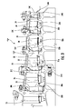
- FIG. 1 a partial section of the axial compressor section of a turbine engine T1 illustrating a method and apparatus for controlling axial compressor blade tip flow according to the present invention is illustrated in Figure 1.
- the turbine engine “T1” includes compressor blades 10-14 and intermediately-positioned stator vanes 15-19 in a casing C1.
- the compressor blades 10-14 include respective leading edges 10A-14A.
- blade 10 is shown in enlarged detail for clarity, and is also exemplary of blades 11-14.
- Air is extracted and pressurized from the area of the leading edge side 10A of the blade 10 through holes 10B in a disk 20.
- the holes 10B communicate with a channel 10C that extends radially outwardly through the blade 10 to the tip where it exits through holes 10D.
- the channel 10C may branch out before exiting the tip of the blade 10.
- the size of the channel 10C and the location and number of the branches is determined empirically based on blade size, shape and volume, and engine performance, rating, tip clearance and similar factors. Note in the drawings that the tip clearance is sufficiently small in relation to the scale of the drawings that actual representation of the tip clearance cannot be shown.
- a turbine engine “T2” includes compressor blades 30-34 and intermediately-positioned stator vanes 35-39 in a casing C2.
- the compressor blades 30-34 include respective trailing edges 30A-34A.
- blade 31 is shown in enlarged detail for clarity, and is exemplary of blades 30 and 32-34. Air is extracted from the area of the trailing edge side 31A of the blade 31 through holes 31B in the disk rim 40.
- the holes 31B communicate with a channel 31C that extends radially outwardly through the blade 31 to the tip where it preferably branches before exiting through holes 31D.
- a turbine engine “T3” includes compressor blades 50-54 and intermediately-positioned stator vanes 55-59 in a casing C3.
- the compressor blades 50-54 include respective leading edges 50A-54A and respective trailing edges 50B-54B.
- FIG. 6 illustrates a blade 52 that is shown in enlarged detail for clarity, and is exemplary of blades 51 and 52-54. Air is extracted from both the areas of the leading edge side 52A and trailing edge side 52B of blade 52 through holes 52C and 52D in the disk rim 60.
- the holes 52C and 52D communicate with channels 52E and 52F, respectively, that extend radially outwardly through the blade 52 to the tip, where they preferably branch before exiting through holes 52G.
- the air discharged at the blade tip reduces or prevents blade tip flow by aerodynamically blocking air flow in the region of the tip clearance between the blade tip and the casing. Air from the inner flow path is brought to the tip clearance, as described above, to form this air block. The pressure of the extracted air increases due to the compressor rotor pumping and, when exiting the blade at the tip, resists air flow across the blade tip from the pressure side to the suction side.
- the methods described above can be applied to both low pressure compressors (boosters) and high pressure compressors. There is no chargeable flow loss when these methods are utilized. Furthermore, by reducing air flow by aerodynamic air blockage rather than by a tight running clearance between the blade tips and the casing, a larger assembly clearance between the blade tips and the casing can be established and maintained. Blade tip rubs are thus reduced, as is recirculation in the inner flow path between the vane and the blade. The extracted air is continuously pumped from the inner flow path to the blade tip, thus providing a continuous air blockage to the blade tip at all times during engine operation.
- the methods described in this application also have application in blisk (blade integrated disk), skewed or circumferential dovetailed blades.
Landscapes
- Engineering & Computer Science (AREA)
- Mechanical Engineering (AREA)
- General Engineering & Computer Science (AREA)
- Structures Of Non-Positive Displacement Pumps (AREA)
Abstract
Description
- This invention relates to a method and apparatus for reducing axial compressor tip flow in airfoils, such as blades and vanes. Blade tip flow in the compressor area of a turbine engine results in loss of compressor efficiency and stall margin. In addition, flow recirculation in seal cavities along the inner flow path between the vanes and blades also degrades compressor performance. One prior art solution for reducing tip flow is to reduce the blade tip clearance. This is done by a variety of means, including control of the casing and vane interface using mechanical and/or thermal methods. These methods can cause tip rubbing, excess wear and loss of engine efficiency.
- According to one aspect of the invention, a method of reducing air flow between a tip of a turbine airfoil rotating in a closely-spaced apart casing is provided, and comprises the step of providing in the airfoil a radially-extending channel having an inlet opening proximate a base of the airfoil and an exit opening on the airfoil tip. Air is extracted and pressurized from a region proximate the base of the airfoil, introduced into the channel and conveyed through the channel to the airfoil tip. The air exits the channel through the exit openings in the airfoil tip into an area between the airfoil tip and casing under sufficient pressure to resist axial air flow from a pressure side to a suction side of the airfoil.
- Another aspect of the invention provides a method of reducing air flow between a tip of a turbine airfoil rotating in a closely-spaced apart casing, comprising the steps of providing a first radially-extending channel having an inlet opening proximate a base of the airfoil on a leading edge side thereof, and an exit opening on the airfoil tip, and providing a second radially-extending channel having an inlet opening proximate the base of the airfoil on a trailing edge side thereof, and an exit opening on the airfoil tip. The air is extracted from a region proximate the base of the airfoil into the channel and pumped through the channel to the airfoil tip. The air exits the channel through the exit openings in the airfoil tip into an area between the airfoil tip and casing under sufficient pressure to resist axial air flow from a pressure side to a suction side of the airfoil.
- In another aspect of the invention a turbine machine compressor airfoil is provided, comprising a airfoil base, a airfoil tip, and an air flow channel extending radially from an air inlet opening in the airfoil proximate the airfoil base to an exit opening in the airfoil tip for providing a air blockage against an axial flow of air from the pressure side of the airfoil to the suction side of the airfoil to thereby reduce compressor airfoil tip flow.
- Various aspects and embodiments of the invention are described below in conjunction with the following drawings, in which:
- Figure 1 is a fragmentary cross-section of an axial flow compressor section of a turbine engine illustrating one embodiment of the invention;
- Figure 2 is an enlarged fragmentary cross-section of a portion of the compressor shown in Figure 1;
- Figure 3 is a fragmentary cross-section of the compressor section of a turbine engine illustrating another embodiment of the invention;
- Figure 4 is an enlarged fragmentary cross-section of a portion of the compressor shown in Figure 3;
- Figure 5 is a fragmentary cross-section of the compressor section of a turbine engine illustrating yet another embodiment of the invention; and
- Figure 6 is an enlarged fragmentary cross-section of a portion of the compressor shown in Figure 5.
- Referring now specifically to the drawings, a partial section of the axial compressor section of a turbine engine T1 illustrating a method and apparatus for controlling axial compressor blade tip flow according to the present invention is illustrated in Figure 1. The turbine engine "T1" includes compressor blades 10-14 and intermediately-positioned stator vanes 15-19 in a casing C1. The compressor blades 10-14 include respective leading
edges 10A-14A. - As is shown in Figure 2,
blade 10 is shown in enlarged detail for clarity, and is also exemplary of blades 11-14. Air is extracted and pressurized from the area of the leadingedge side 10A of theblade 10 throughholes 10B in adisk 20. Theholes 10B communicate with achannel 10C that extends radially outwardly through theblade 10 to the tip where it exits throughholes 10D. Note that thechannel 10C may branch out before exiting the tip of theblade 10. The size of thechannel 10C and the location and number of the branches is determined empirically based on blade size, shape and volume, and engine performance, rating, tip clearance and similar factors. Note in the drawings that the tip clearance is sufficiently small in relation to the scale of the drawings that actual representation of the tip clearance cannot be shown. - Referring now to Figure 3, a turbine engine "T2" includes compressor blades 30-34 and intermediately-positioned stator vanes 35-39 in a casing C2. The compressor blades 30-34 include respective
trailing edges 30A-34A. - In Figure 4,
blade 31 is shown in enlarged detail for clarity, and is exemplary ofblades 30 and 32-34. Air is extracted from the area of thetrailing edge side 31A of theblade 31 throughholes 31B in thedisk rim 40. Theholes 31B communicate with achannel 31C that extends radially outwardly through theblade 31 to the tip where it preferably branches before exiting throughholes 31D. - Referring now to Figure 5, a turbine engine "T3" includes compressor blades 50-54 and intermediately-positioned stator vanes 55-59 in a casing C3. The compressor blades 50-54 include respective leading
edges 50A-54A and respectivetrailing edges 50B-54B. - Figure 6 illustrates a
blade 52 that is shown in enlarged detail for clarity, and is exemplary ofblades 51 and 52-54. Air is extracted from both the areas of the leadingedge side 52A andtrailing edge side 52B ofblade 52 throughholes disk rim 60. Theholes channels blade 52 to the tip, where they preferably branch before exiting throughholes 52G. - In each of the embodiments described above, the air discharged at the blade tip reduces or prevents blade tip flow by aerodynamically blocking air flow in the region of the tip clearance between the blade tip and the casing. Air from the inner flow path is brought to the tip clearance, as described above, to form this air block. The pressure of the extracted air increases due to the compressor rotor pumping and, when exiting the blade at the tip, resists air flow across the blade tip from the pressure side to the suction side.
- The methods described above can be applied to both low pressure compressors (boosters) and high pressure compressors. There is no chargeable flow loss when these methods are utilized. Furthermore, by reducing air flow by aerodynamic air blockage rather than by a tight running clearance between the blade tips and the casing, a larger assembly clearance between the blade tips and the casing can be established and maintained. Blade tip rubs are thus reduced, as is recirculation in the inner flow path between the vane and the blade. The extracted air is continuously pumped from the inner flow path to the blade tip, thus providing a continuous air blockage to the blade tip at all times during engine operation.
- The methods described in this application also have application in blisk (blade integrated disk), skewed or circumferential dovetailed blades.
- A method and apparatus for controlling axial compressor blade tip flow is described above. Various details of the invention may be changed without departing from its scope. Furthermore, the foregoing description of the preferred embodiment of the invention and the best mode for practicing the invention are provided for the purpose of illustration only and not for the purpose of limitation--the invention being defined by the claims.
-
T1 turbine machine T2 turbine machine T3 turbine machine C1 casing C3 casing 10 blades 10A leading edge 10B inlet openings 10C channel 10D exit openings 11 blades 11C channel 12 blades 12C channel 13 blades 13C channel 14 blades 14C channel 15 stationary vanes 16 stationary vanes 17 stationary vanes 18 stationary vanes 19 stationary vanes 20 disk 31 blade 31A trailing edge 31B inlet opening 31C channel 31D exit opening 50 blade 50A leading edge 50B trailing edge 50C inlet opening 50D inlet opening 50F channel 52 blade 52A leading edge 52B trailing edge 52C inlet opening 52D inlet opening 52E first channel 52F second channel 52G exit holes
Claims (10)
- A turbine machine (T1) of the type having a high pressure compressor positioned in a casing (C1), a plurality of rotating compressor blades (10-14) having respective blade tips, respective blade bases affixed to a central disk (20), and a plurality of stationary vanes (15-19) positioned between respective ones of the blades (10-14), comprising at least one air channel (10C, 11C, 12C, 13C, 14C) formed in respective ones of the blades (10-14) for air flow communication from the base to the tip for extracting and pressurizing air from an inner area proximate the disk (20) and conveying the extracted and pressurized air through the channel (10C, 11C, 12C, 13C, 14C) into an area between the blade tip and casing (C1) for blocking air flow from a tip of the blades (10-14).
- A turbine machine (T1) according to claim 1, wherein the channel (10C) exits the blade tip through a respective plurality of exit holes (10D).
- A turbine machine (T1) according to claim 1 or claim 2, wherein the channel (10C) includes an air inlet (10B) opening in on leading edge (10A) of the blade (10).
- A turbine machine (T2) according to any preceding claim, wherein the channel (31 C) includes an air inlet opening (31B) on a trailing edge (31A) side of the blade (31).
- A turbine machine (T3) according to any preceding claim, wherein the channel (50F) includes an air inlet opening (50C) in on a leading edge (50A) side and an air inlet opening (50D) on a trailing edge (50B) side of the blade (50).
- A turbine machine (T3) according to any preceding claim, and including a first channel (52E) having an air inlet opening (52C) on a leading edge (52A) side of the blade (52) and a second channel (52F) having an air inlet opening (52D) on a trailing edge (52B) side of the blade (52).
- A turbine machine (T1) according to any preceding claim, wherein the channel (50F) includes a plurality of exit holes (52G) in the blade tip.
- A method of reducing air flow between a tip of a turbine airfoil (10) rotating in a closely-spaced apart casing (C1), comprising the steps of:(a) providing in the airfoil (10) a radially-extending channel (10C) having an inlet opening (10B) proximate a base of the airfoil (10) and an exit opening (10D) on the airfoil tip;(b) extracting and pressurizing air from a region proximate the base of the airfoil (10) into the channel (10C);(c) conveying the air through the channel (10C) to the airfoil tip; and(d) discharging the air through the exit openings (10D) in the airfoil tip into an area between the airfoil tip and casing (C1) under sufficient pressure to resist axial air flow across the tip of the airfoil (10).
- A method according to claim 8, wherein the step of providing a radially-extending channel (10C) having an inlet opening (10B) proximate a base of the airfoil (10) and an exit opening (10D) on the airfoil tip includes the step of forming the inlet opening (10B) on a leading edge (10A) side of the airfoil (10).
- A method according to claim 8 or claim 9, wherein the step of providing a radially-extending channel (31C) having an inlet opening (31B) proximate a base of the airfoil (31) and an exit opening (31D) on the airfoil tip includes the step of forming the inlet opening (31B) on a trailing edge (31A) side of the blade (31).
Applications Claiming Priority (1)
| Application Number | Priority Date | Filing Date | Title |
|---|---|---|---|
| US11/164,636 US20070122280A1 (en) | 2005-11-30 | 2005-11-30 | Method and apparatus for reducing axial compressor blade tip flow |
Publications (2)
| Publication Number | Publication Date |
|---|---|
| EP1793089A2 true EP1793089A2 (en) | 2007-06-06 |
| EP1793089A3 EP1793089A3 (en) | 2007-10-24 |
Family
ID=37685846
Family Applications (1)
| Application Number | Title | Priority Date | Filing Date |
|---|---|---|---|
| EP06125091A Ceased EP1793089A3 (en) | 2005-11-30 | 2006-11-30 | Method and apparatus for reducing axial compressor blade tip flow |
Country Status (5)
| Country | Link |
|---|---|
| US (1) | US20070122280A1 (en) |
| EP (1) | EP1793089A3 (en) |
| JP (1) | JP2007154887A (en) |
| CN (1) | CN101008402A (en) |
| CA (1) | CA2569177A1 (en) |
Cited By (3)
| Publication number | Priority date | Publication date | Assignee | Title |
|---|---|---|---|---|
| GB2452297B (en) * | 2007-08-30 | 2010-01-06 | Rolls Royce Plc | A compressor |
| CN102628452A (en) * | 2012-03-21 | 2012-08-08 | 朱晓义 | Air compressor and automobile engine |
| EP2250347B1 (en) * | 2008-02-28 | 2017-11-29 | MTU Aero Engines GmbH | Axial compressor with a device for redirecting a leakage flow |
Families Citing this family (4)
| Publication number | Priority date | Publication date | Assignee | Title |
|---|---|---|---|---|
| US20100275574A1 (en) * | 2009-04-30 | 2010-11-04 | General Electric Company | Borescope plug with bristles |
| DE102012215895A1 (en) * | 2012-09-07 | 2014-03-13 | Robert Bosch Gmbh | Paddle wheel for a turbomachine and method for producing a turbine wheel for a turbomachine |
| CN103925244B (en) * | 2014-04-02 | 2017-03-15 | 清华大学 | A kind of big flow high load axial compressor and fan for 300MW F level heavy duty gas turbines |
| JP6468532B2 (en) * | 2015-04-27 | 2019-02-13 | 三菱日立パワーシステムズ株式会社 | Compressor rotor, compressor, and gas turbine |
Citations (4)
| Publication number | Priority date | Publication date | Assignee | Title |
|---|---|---|---|---|
| GB2165315A (en) | 1984-10-04 | 1986-04-09 | Rolls Royce | Improvements in or relating to hollow fluid cooled turbine blades |
| EP0278434A2 (en) | 1987-02-06 | 1988-08-17 | Wolfgang P. Weinhold | A blade, especially a rotor blade |
| US5688107A (en) | 1992-12-28 | 1997-11-18 | United Technologies Corp. | Turbine blade passive clearance control |
| GB2409247A (en) | 2003-12-20 | 2005-06-22 | Rolls Royce Plc | A seal arrangement |
Family Cites Families (20)
| Publication number | Priority date | Publication date | Assignee | Title |
|---|---|---|---|---|
| JPS4825103U (en) * | 1971-08-06 | 1973-03-24 | ||
| CH582305A5 (en) * | 1974-09-05 | 1976-11-30 | Bbc Sulzer Turbomaschinen | |
| GB1514613A (en) * | 1976-04-08 | 1978-06-14 | Rolls Royce | Blade or vane for a gas turbine engine |
| JPS5713201A (en) * | 1980-06-30 | 1982-01-23 | Hitachi Ltd | Air cooled gas turbine blade |
| JPS6081204U (en) * | 1983-11-10 | 1985-06-05 | 三菱重工業株式会社 | Cooling structure of turbine rotor blades and stationary blades |
| US4761116A (en) * | 1987-05-11 | 1988-08-02 | General Electric Company | Turbine blade with tip vent |
| US5667359A (en) * | 1988-08-24 | 1997-09-16 | United Technologies Corp. | Clearance control for the turbine of a gas turbine engine |
| US5358378A (en) * | 1992-11-17 | 1994-10-25 | Holscher Donald J | Multistage centrifugal compressor without seals and with axial thrust balance |
| US5403158A (en) * | 1993-12-23 | 1995-04-04 | United Technologies Corporation | Aerodynamic tip sealing for rotor blades |
| US5387085A (en) * | 1994-01-07 | 1995-02-07 | General Electric Company | Turbine blade composite cooling circuit |
| CA2262701C (en) * | 1997-06-06 | 2003-02-18 | Mitsubishi Heavy Industries, Ltd. | Gas turbine blade |
| JP2955252B2 (en) * | 1997-06-26 | 1999-10-04 | 三菱重工業株式会社 | Gas turbine blade tip shroud |
| US6574965B1 (en) * | 1998-12-23 | 2003-06-10 | United Technologies Corporation | Rotor tip bleed in gas turbine engines |
| US6206638B1 (en) * | 1999-02-12 | 2001-03-27 | General Electric Company | Low cost airfoil cooling circuit with sidewall impingement cooling chambers |
| DE19921644B4 (en) * | 1999-05-10 | 2012-01-05 | Alstom | Coolable blade for a gas turbine |
| US6382914B1 (en) * | 2001-02-23 | 2002-05-07 | General Electric Company | Cooling medium transfer passageways in radial cooled turbine blades |
| EP1247939A1 (en) * | 2001-04-06 | 2002-10-09 | Siemens Aktiengesellschaft | Turbine blade and process of manufacturing such a blade |
| US6494678B1 (en) * | 2001-05-31 | 2002-12-17 | General Electric Company | Film cooled blade tip |
| DE10205363A1 (en) * | 2002-02-08 | 2003-08-21 | Rolls Royce Deutschland | gas turbine |
| US7137782B2 (en) * | 2004-04-27 | 2006-11-21 | General Electric Company | Turbulator on the underside of a turbine blade tip turn and related method |
-
2005
- 2005-11-30 US US11/164,636 patent/US20070122280A1/en not_active Abandoned
-
2006
- 2006-11-29 CA CA002569177A patent/CA2569177A1/en not_active Abandoned
- 2006-11-30 CN CNA2006101729989A patent/CN101008402A/en active Pending
- 2006-11-30 JP JP2006323501A patent/JP2007154887A/en active Pending
- 2006-11-30 EP EP06125091A patent/EP1793089A3/en not_active Ceased
Patent Citations (4)
| Publication number | Priority date | Publication date | Assignee | Title |
|---|---|---|---|---|
| GB2165315A (en) | 1984-10-04 | 1986-04-09 | Rolls Royce | Improvements in or relating to hollow fluid cooled turbine blades |
| EP0278434A2 (en) | 1987-02-06 | 1988-08-17 | Wolfgang P. Weinhold | A blade, especially a rotor blade |
| US5688107A (en) | 1992-12-28 | 1997-11-18 | United Technologies Corp. | Turbine blade passive clearance control |
| GB2409247A (en) | 2003-12-20 | 2005-06-22 | Rolls Royce Plc | A seal arrangement |
Cited By (4)
| Publication number | Priority date | Publication date | Assignee | Title |
|---|---|---|---|---|
| GB2452297B (en) * | 2007-08-30 | 2010-01-06 | Rolls Royce Plc | A compressor |
| EP2250347B1 (en) * | 2008-02-28 | 2017-11-29 | MTU Aero Engines GmbH | Axial compressor with a device for redirecting a leakage flow |
| CN102628452A (en) * | 2012-03-21 | 2012-08-08 | 朱晓义 | Air compressor and automobile engine |
| CN102628452B (en) * | 2012-03-21 | 2014-07-16 | 朱晓义 | Air compressor and automobile engine |
Also Published As
| Publication number | Publication date |
|---|---|
| CN101008402A (en) | 2007-08-01 |
| JP2007154887A (en) | 2007-06-21 |
| EP1793089A3 (en) | 2007-10-24 |
| CA2569177A1 (en) | 2007-05-30 |
| US20070122280A1 (en) | 2007-05-31 |
Similar Documents
| Publication | Publication Date | Title |
|---|---|---|
| US6174135B1 (en) | Turbine blade trailing edge cooling openings and slots | |
| JP4644465B2 (en) | Split flow turbine nozzle | |
| CN101178014B (en) | Dual interstage cooled engine | |
| JP4492951B2 (en) | Triple circuit turbine cooling | |
| US8262340B2 (en) | Turbomachine exerting dynamic influence on the flow | |
| EP3124794B1 (en) | Axial flow compressor with end-wall contouring | |
| US6361277B1 (en) | Methods and apparatus for directing airflow to a compressor bore | |
| CN106574509B (en) | Compressor airfoil | |
| CN101178013B (en) | Combined nozzle cooled engine | |
| CN1568397A (en) | Methods and apparatus for cooling gas turbine engine blade tips | |
| CN104508247B (en) | Turbine airfoil and manufacturing method thereof | |
| US7270519B2 (en) | Methods and apparatus for reducing flow across compressor airfoil tips | |
| US6579065B2 (en) | Methods and apparatus for limiting fluid flow between adjacent rotor blades | |
| US20180230806A1 (en) | Undulating tip shroud for use on a turbine blade | |
| WO2020039690A1 (en) | Blade and gas turbine | |
| US7011495B2 (en) | Fluid flow machine (turbomachine) with increased rotor-stator ratio | |
| JP2004324646A (en) | Method and apparatus for structurally supporting an airfoil tip | |
| US7874794B2 (en) | Blade row for a rotary machine and method of fabricating same | |
| EP1793089A2 (en) | Method and apparatus for reducing axial compressor blade tip flow | |
| US7363762B2 (en) | Gas turbine engines seal assembly and methods of assembling the same | |
| US7661924B2 (en) | Method and apparatus for assembling turbine engines | |
| CN111434894A (en) | Plug-in system for fins and method of installing the same | |
| CN107084006B (en) | Accelerator insert for a gas turbine engine airfoil | |
| US12055070B2 (en) | Stationary blade segment, gas turbine, and method for producing stationary blade segment | |
| US11946387B2 (en) | Turbine engine blade with improved cooling |
Legal Events
| Date | Code | Title | Description |
|---|---|---|---|
| PUAI | Public reference made under article 153(3) epc to a published international application that has entered the european phase |
Free format text: ORIGINAL CODE: 0009012 |
|
| AK | Designated contracting states |
Kind code of ref document: A2 Designated state(s): AT BE BG CH CY CZ DE DK EE ES FI FR GB GR HU IE IS IT LI LT LU LV MC NL PL PT RO SE SI SK TR |
|
| AX | Request for extension of the european patent |
Extension state: AL BA HR MK YU |
|
| PUAL | Search report despatched |
Free format text: ORIGINAL CODE: 0009013 |
|
| AK | Designated contracting states |
Kind code of ref document: A3 Designated state(s): AT BE BG CH CY CZ DE DK EE ES FI FR GB GR HU IE IS IT LI LT LU LV MC NL PL PT RO SE SI SK TR |
|
| AX | Request for extension of the european patent |
Extension state: AL BA HR MK YU |
|
| 17P | Request for examination filed |
Effective date: 20080424 |
|
| RAP1 | Party data changed (applicant data changed or rights of an application transferred) |
Owner name: GENERAL ELECTRIC COMPANY |
|
| AKX | Designation fees paid |
Designated state(s): DE FR GB IT SE |
|
| 17Q | First examination report despatched |
Effective date: 20080613 |
|
| STAA | Information on the status of an ep patent application or granted ep patent |
Free format text: STATUS: THE APPLICATION HAS BEEN REFUSED |
|
| 18R | Application refused |
Effective date: 20100607 |