JP6468532B2 - Compressor rotor, compressor, and gas turbine - Google Patents
Compressor rotor, compressor, and gas turbine Download PDFInfo
- Publication number
- JP6468532B2 JP6468532B2 JP2015090289A JP2015090289A JP6468532B2 JP 6468532 B2 JP6468532 B2 JP 6468532B2 JP 2015090289 A JP2015090289 A JP 2015090289A JP 2015090289 A JP2015090289 A JP 2015090289A JP 6468532 B2 JP6468532 B2 JP 6468532B2
- Authority
- JP
- Japan
- Prior art keywords
- cavity
- flow path
- axial
- air
- radial
- Prior art date
- Legal status (The legal status is an assumption and is not a legal conclusion. Google has not performed a legal analysis and makes no representation as to the accuracy of the status listed.)
- Active
Links
Images


Classifications
-
- F—MECHANICAL ENGINEERING; LIGHTING; HEATING; WEAPONS; BLASTING
- F04—POSITIVE - DISPLACEMENT MACHINES FOR LIQUIDS; PUMPS FOR LIQUIDS OR ELASTIC FLUIDS
- F04D—NON-POSITIVE-DISPLACEMENT PUMPS
- F04D29/00—Details, component parts, or accessories
- F04D29/26—Rotors specially for elastic fluids
- F04D29/32—Rotors specially for elastic fluids for axial flow pumps
- F04D29/321—Rotors specially for elastic fluids for axial flow pumps for axial flow compressors
- F04D29/324—Blades
-
- F—MECHANICAL ENGINEERING; LIGHTING; HEATING; WEAPONS; BLASTING
- F02—COMBUSTION ENGINES; HOT-GAS OR COMBUSTION-PRODUCT ENGINE PLANTS
- F02C—GAS-TURBINE PLANTS; AIR INTAKES FOR JET-PROPULSION PLANTS; CONTROLLING FUEL SUPPLY IN AIR-BREATHING JET-PROPULSION PLANTS
- F02C7/00—Features, components parts, details or accessories, not provided for in, or of interest apart form groups F02C1/00 - F02C6/00; Air intakes for jet-propulsion plants
- F02C7/12—Cooling of plants
- F02C7/16—Cooling of plants characterised by cooling medium
- F02C7/18—Cooling of plants characterised by cooling medium the medium being gaseous, e.g. air
-
- F—MECHANICAL ENGINEERING; LIGHTING; HEATING; WEAPONS; BLASTING
- F04—POSITIVE - DISPLACEMENT MACHINES FOR LIQUIDS; PUMPS FOR LIQUIDS OR ELASTIC FLUIDS
- F04D—NON-POSITIVE-DISPLACEMENT PUMPS
- F04D29/00—Details, component parts, or accessories
- F04D29/26—Rotors specially for elastic fluids
- F04D29/32—Rotors specially for elastic fluids for axial flow pumps
- F04D29/321—Rotors specially for elastic fluids for axial flow pumps for axial flow compressors
-
- F—MECHANICAL ENGINEERING; LIGHTING; HEATING; WEAPONS; BLASTING
- F04—POSITIVE - DISPLACEMENT MACHINES FOR LIQUIDS; PUMPS FOR LIQUIDS OR ELASTIC FLUIDS
- F04D—NON-POSITIVE-DISPLACEMENT PUMPS
- F04D29/00—Details, component parts, or accessories
- F04D29/58—Cooling; Heating; Diminishing heat transfer
- F04D29/582—Cooling; Heating; Diminishing heat transfer specially adapted for elastic fluid pumps
- F04D29/584—Cooling; Heating; Diminishing heat transfer specially adapted for elastic fluid pumps cooling or heating the machine
-
- F—MECHANICAL ENGINEERING; LIGHTING; HEATING; WEAPONS; BLASTING
- F02—COMBUSTION ENGINES; HOT-GAS OR COMBUSTION-PRODUCT ENGINE PLANTS
- F02C—GAS-TURBINE PLANTS; AIR INTAKES FOR JET-PROPULSION PLANTS; CONTROLLING FUEL SUPPLY IN AIR-BREATHING JET-PROPULSION PLANTS
- F02C3/00—Gas-turbine plants characterised by the use of combustion products as the working fluid
- F02C3/04—Gas-turbine plants characterised by the use of combustion products as the working fluid having a turbine driving a compressor
-
- F—MECHANICAL ENGINEERING; LIGHTING; HEATING; WEAPONS; BLASTING
- F04—POSITIVE - DISPLACEMENT MACHINES FOR LIQUIDS; PUMPS FOR LIQUIDS OR ELASTIC FLUIDS
- F04D—NON-POSITIVE-DISPLACEMENT PUMPS
- F04D19/00—Axial-flow pumps
- F04D19/02—Multi-stage pumps
-
- F—MECHANICAL ENGINEERING; LIGHTING; HEATING; WEAPONS; BLASTING
- F05—INDEXING SCHEMES RELATING TO ENGINES OR PUMPS IN VARIOUS SUBCLASSES OF CLASSES F01-F04
- F05D—INDEXING SCHEME FOR ASPECTS RELATING TO NON-POSITIVE-DISPLACEMENT MACHINES OR ENGINES, GAS-TURBINES OR JET-PROPULSION PLANTS
- F05D2220/00—Application
- F05D2220/30—Application in turbines
- F05D2220/32—Application in turbines in gas turbines
-
- F—MECHANICAL ENGINEERING; LIGHTING; HEATING; WEAPONS; BLASTING
- F05—INDEXING SCHEMES RELATING TO ENGINES OR PUMPS IN VARIOUS SUBCLASSES OF CLASSES F01-F04
- F05D—INDEXING SCHEME FOR ASPECTS RELATING TO NON-POSITIVE-DISPLACEMENT MACHINES OR ENGINES, GAS-TURBINES OR JET-PROPULSION PLANTS
- F05D2240/00—Components
- F05D2240/35—Combustors or associated equipment
Description
本発明は、圧縮機ケーシング内で軸線を中心として回転する圧縮機ロータ、圧縮機、及びガスタービンに関する。 The present invention relates to a compressor rotor, a compressor, and a gas turbine that rotate about an axis in a compressor casing.
圧縮機は、ケーシングと、このケーシング内で軸線を中心として回転するロータと、を備えている。軸流圧縮機のロータは、軸線を中心として軸方向に延びているロータ軸と、ロータ軸の外周に固定され軸方向に並んでいる複数の動翼列と、を有する。 The compressor includes a casing and a rotor that rotates around the axis in the casing. The rotor of the axial compressor has a rotor shaft that extends in the axial direction around the axis, and a plurality of blade rows that are fixed to the outer periphery of the rotor shaft and aligned in the axial direction.
このような軸流圧縮機のロータとしては、以下の特許文献1に開示されているものがある。このロータには、ロータの軽量化等のために複数のチャンバ(又はキャビティ)が形成されている。複数のチャンバのうち、第一チャンバと第二チャンバとは、径方向の位置が互いに同じで軸方向に並んでいる。第二チャンバは、第一チャンバに対して軸方向の上流側に位置している。また、複数のチャンバのうち、第三チャンバは、軸方向における第一チャンバと第二チャンバとの間の位置であって第一チャンバ及び第二チャンバよりも径方向内側の位置に形成されている。第一チャンバ及び第二チャンバは、いずれも、ロータ軸の外周側とケーシングの内周側との間の環状の空間で形成される空気圧縮流路と連通している。第三チャンバは、第一チャンバに連通していると共に、第二チャンバにも連通している。 As a rotor of such an axial compressor, there is one disclosed in Patent Document 1 below. In this rotor, a plurality of chambers (or cavities) are formed in order to reduce the weight of the rotor. Among the plurality of chambers, the first chamber and the second chamber have the same radial position and are aligned in the axial direction. The second chamber is located upstream in the axial direction with respect to the first chamber. In addition, among the plurality of chambers, the third chamber is formed at a position between the first chamber and the second chamber in the axial direction and radially inward of the first chamber and the second chamber. . Both of the first chamber and the second chamber communicate with an air compression flow path formed by an annular space between the outer peripheral side of the rotor shaft and the inner peripheral side of the casing. The third chamber communicates with the first chamber and also communicates with the second chamber.
空気圧縮流路中の空気の一部は、第二チャンバよりも下流側に位置している第一チャンバ内に流入する。この空気は、第一チャンバから第三チャンバ内に流入してから、第二チャンバを経て、空気圧縮流路中に戻る。 Part of the air in the air compression flow path flows into the first chamber located downstream from the second chamber. This air flows from the first chamber into the third chamber and then returns to the air compression flow path through the second chamber.
特許文献1に開示されている技術では、空気圧縮流路中の空気の一部を各チャンバを経て空気圧縮流路に戻すことで、空気圧縮流路を流れる空気の温度変化に対するロータ軸の熱応答性を高めている。 In the technique disclosed in Patent Document 1, a part of the air in the air compression passage is returned to the air compression passage through each chamber, so that the heat of the rotor shaft with respect to the temperature change of the air flowing through the air compression passage. Increases responsiveness.
本発明は、気体圧縮流路を流れる気体の温度変化に対するロータ軸の熱応答性をより高めることができる圧縮機ロータ、この圧縮機ロータを備える圧縮機、及びこの圧縮機を備えるガスタービンを提供することを目的とする。 The present invention provides a compressor rotor capable of further improving the thermal responsiveness of a rotor shaft to a temperature change of a gas flowing in a gas compression flow path, a compressor including the compressor rotor, and a gas turbine including the compressor. The purpose is to do.
上記目的を達成するための発明に係る一態様としての圧縮機ロータは、
圧縮機ケーシング内で軸線を中心として回転する圧縮機ロータにおいて、前記軸線を中心として、軸方向に延びているロータ軸と、前記ロータ軸の外周に固定され、前記軸方向に並んでいる複数の動翼列と、を備え、前記ロータ軸には、複数の前記動翼列の相互間の軸方向における各位置に、前記軸線を中心として環状を成し、前記軸線に対する径方向で互いに離間している複数のキャビティで構成されるキャビティ群が形成され、前記ロータ軸の外周側であって前記軸方向で複数の前記動翼列が存在する気体圧縮流路中を気体が流れてくる圧力の低い側が前記軸方向における上流側を成し、前記上流側の反対側で気体の圧力が高くなる側が前記軸方向における下流側を成し、前記キャビティ群を構成する複数の前記キャビティのうちで、最も径方向外側のキャビティが外側キャビティを成し、前記外側キャビティよりも径方向内側のいずれかのキャビティが軸方向連通キャビティを成し、少なくとも二つの前記キャビティ群のうち、上流側の一以上のキャビティ群が上流側キャビティ群を成し、前記上流側キャビティ群に対して下流側に位置する残りのキャビティ群が下流側キャビティ群を成し、前記ロータ軸には、さらに、前記気体圧縮流路中の気体を、前記下流側キャビティ群の前記外側キャビティに流入させる入口流路と、前記下流側キャビティ群の前記外側キャビティ内に流入した気体が前記下流側キャビティ群の前記軸方向連通キャビティに至るよう、前記径方向を含む方向に延びて、該外側キャビティから該軸方向連通キャビティまでの複数のキャビティで、前記径方向で隣り合う二つのキャビティ相互を連通させる径方向流路と、前記軸方向を含む方向に延びて、前記下流側キャビティ群の前記軸方向連通キャビティと前記上流側キャビティ群の前記軸方向連通キャビティとを連通させる軸方向流路と、前記上流側キャビティ群の前記軸方向連通キャビティ内の気体が前記上流側キャビティ群の前記外側キャビティに至るよう、前記径方向を含む方向に延びて、該軸方向連通キャビティから該外側キャビティまでの複数のキャビティで、前記径方向で隣り合う二つのキャビティ相互を連通させる径方向流路と、前記上流側キャビティ群の前記外側キャビティ内の気体を前記気体圧縮流路中に流出させる出口流路と、が形成され、前記軸方向流路における前記下流側キャビティ群の前記軸方向連通キャビティに対する開口である入口開口の径方向外側縁は、環状の該軸方向連通キャビティを画定する内周面のうちの径方向外側内周面よりも径方向内側に位置し、前記軸方向流路における前記上流側キャビティ群の前記軸方向連通キャビティに対する開口である出口開口の径方向外側縁は、環状の該軸方向連通キャビティを画定する内周面のうちの径方向外側内周面よりも径方向内側に位置する。前記ロータ軸は、前記軸方向で互いに積層されている複数のロータディスクと、前記径方向に延びて、前記軸方向で隣接する前記ロータディスクのそれぞれに係合して、隣接するロータディスク相互の相対回転を規制するトルクピンと、を有し、前記トルクピンは、前記下流側キャビティ群を構成する複数のキャビティのうちで前記径方向で隣り合うキャビティの相互間の位置と、前記上流側キャビティ群を構成する複数のキャビティのうちで前記径方向で隣り合うキャビティの相互間の位置と、に配置され、前記トルクピンには、前記径方向に貫通する貫通孔が形成され、前記貫通孔が前記径方向流路を形成する。
The compressor rotor as one aspect according to the invention for achieving the above object is as follows:
In a compressor rotor that rotates about an axis in a compressor casing, a rotor shaft that extends in the axial direction around the axis, and a plurality of rotor shafts that are fixed to an outer periphery of the rotor shaft and aligned in the axial direction A row of rotor blades, and the rotor shaft has an annular shape around the axis at each position in the axial direction between the plurality of blade rows, and is spaced apart from each other in the radial direction with respect to the axis. A cavity group composed of a plurality of cavities is formed, and the pressure at which the gas flows through the gas compression flow path on the outer peripheral side of the rotor shaft and in the axial direction where the plurality of moving blade rows are present. The lower side forms the upstream side in the axial direction, the side where the gas pressure increases on the opposite side of the upstream side forms the downstream side in the axial direction, and among the plurality of cavities constituting the cavity group, Most A radially outer cavity forms an outer cavity, and any cavity radially inward of the outer cavity forms an axial communication cavity, and one or more cavities upstream of at least two of the cavity groups The group forms an upstream cavity group, the remaining cavity group located downstream from the upstream cavity group forms a downstream cavity group, and the rotor shaft further includes a gas compression channel. An inlet flow channel for allowing the gas in the downstream cavity group to flow into the outer cavity, and the gas flowing into the outer cavity in the downstream cavity group to reach the axial communication cavity in the downstream cavity group A plurality of cavities extending in a direction including the radial direction and extending from the outer cavity to the axial communication cavity. A radial flow path that connects two cavities adjacent to each other in a direction, and the axial communication cavity of the downstream cavity group and the axial communication cavity of the upstream cavity group extending in a direction including the axial direction. An axial flow path that communicates with each other, and the gas in the axial communication cavity of the upstream cavity group extends in a direction including the radial direction so as to reach the outer cavity of the upstream cavity group, and the shaft A plurality of cavities from a directional communication cavity to the outer cavity, a radial flow path communicating two cavities adjacent in the radial direction, and a gas in the outer cavity of the upstream cavity group. And an outlet flow channel that flows into the channel, and the axial communication cavity of the downstream cavity group in the axial flow channel. A radially outer edge of the inlet opening that is an opening with respect to the inner circumferential surface that defines the annular axial communication cavity is located radially inward of the radially outer inner circumferential surface, The radially outer edge of the outlet opening, which is an opening to the axial communication cavity of the upstream cavity group, is more radial than the radially outer inner surface of the inner peripheral surface defining the annular axial communication cavity. Located inside. The rotor shaft is engaged with each of a plurality of rotor disks stacked in the axial direction and the rotor disks that extend in the radial direction and are adjacent to each other in the axial direction. A torque pin that regulates relative rotation, and the torque pin includes a position between the cavities adjacent in the radial direction among the plurality of cavities constituting the downstream cavity group, and the upstream cavity group. Among the plurality of cavities that are configured, they are arranged at positions between cavities adjacent in the radial direction, and the torque pin is formed with a through-hole penetrating in the radial direction, and the through-hole is in the radial direction A flow path is formed.
当該圧縮機ロータでは、気体圧縮流路内の軸方向における圧力差をドライビングフォースとして、気体圧縮流路中の気体の一部が、入口流路を経て下流側キャビティ群の外側キャビティに流入する。外側キャビティに流入した気体は、径方向流路を経て、場合によってはさらに一以上のキャビティを経て、下流側キャビティ群の軸方向連通キャビティに流入する。下流側キャビティ群の軸方向連通キャビティに流入した気体は、軸方向流路を経て、上流側キャビティ群の軸方向連通キャビティに流入する。上流側キャビティ群の軸方向連通キャビティに流入した気体は、径方向流路を経て、場合によってはさらに一以上のキャビティを経て、上流側キャビティ群の外側キャビティに流入する。上流側キャビティ群の外側キャビティに流入した気体は、出口流路を経て気体圧縮流路に戻る。 In the compressor rotor, a pressure difference in the axial direction in the gas compression channel is used as a driving force, and a part of the gas in the gas compression channel flows into the outer cavity of the downstream cavity group through the inlet channel. The gas that has flowed into the outer cavity flows through the radial flow path, and possibly through one or more cavities, and then flows into the axial communication cavity of the downstream cavity group. The gas that has flowed into the axial communication cavity of the downstream cavity group flows through the axial flow path into the axial communication cavity of the upstream cavity group. The gas that has flowed into the axial communication cavity of the upstream side cavity group flows into the outer cavity of the upstream side cavity group through the radial flow path, and possibly further through one or more cavities. The gas that has flowed into the outer cavity of the upstream cavity group returns to the gas compression channel through the outlet channel.
よって、当該圧縮機ロータでは、空気圧縮流路内の軸方向における圧力差をドライビングフォースとして、下流側キャビティ群の外側キャビティ、下流側キャビティ群の外側キャビティと軸方向連通キャビティとの間のキャビティ、さらに、上流側キャビティ群の外側キャビティ、上流側キャビティ群の外側キャビティと軸方向連通キャビティとの間のキャビティ内を、気体圧縮流路中の気体の一部で効率的に換気することができる。さらに、当該圧縮機ロータでは、下流側キャビティ群の軸方向連通キャビティ内における径方向外側縁から径方向で軸方向流路が開口している位置までの間、さらに、上流側キャビティ群の軸方向連通キャビティ内における径方向外側縁から径方向で軸方向流路が開口している位置までの間も、気体圧縮流路中の気体で効率的に換気することができる。さらに、当該圧縮機ロータでは、キャビティ内を流れる空気とこのキャビティとの周速差により、キャビティを画定する壁面の熱伝達率を高めることができる。 Therefore, in the compressor rotor, the pressure difference in the axial direction in the air compression flow path is used as a driving force, the outer cavity of the downstream cavity group, the cavity between the outer cavity of the downstream cavity group and the axial communication cavity, Furthermore, the inside of the cavity between the outer cavity of the upstream cavity group and the outer cavity of the upstream cavity group and the axial communication cavity can be efficiently ventilated with a part of the gas in the gas compression flow path. Further, in the compressor rotor, from the radially outer edge in the axial communication cavity of the downstream cavity group to the position where the axial flow path is opened in the radial direction, further in the axial direction of the upstream cavity group Even from the radially outer edge in the communication cavity to the position where the axial flow path is opened in the radial direction, the gas in the gas compression flow path can be efficiently ventilated. Further, in the compressor rotor, the heat transfer coefficient of the wall surface defining the cavity can be increased by the difference in the peripheral velocity between the air flowing in the cavity and the cavity.
従って、当該圧縮機ロータでは、気体圧縮流路を流れる気体の温度変化に対する圧縮機ロータの熱応答性を高めることができる。
さらに、当該圧縮機ロータでは、トルクピンに貫通孔を形成すれば、ロータディスクに径方向流路を形成する必要がない。このため、当該圧縮機ロータでは、ロータディスクの加工工数の増加を抑えることができる。
Therefore, in the compressor rotor, the thermal responsiveness of the compressor rotor with respect to the temperature change of the gas flowing through the gas compression channel can be improved.
Further, in the compressor rotor, if a through hole is formed in the torque pin, it is not necessary to form a radial flow path in the rotor disk. For this reason, in the compressor rotor, an increase in the processing man-hour of the rotor disk can be suppressed.
ここで、前記圧縮機ロータにおいて、前記軸方向流路における前記入口開口の径方向外側縁は、前記下流側キャビティ群の前記軸方向連通キャビティの径方向における中央位置よりも径方向内側に位置し、前記軸方向流路における前記出口開口の径方向外側縁は、前記上流側キャビティ群の前記軸方向連通キャビティの径方向における中央位置よりも径方向内側に位置してもよい。 Here, in the compressor rotor, a radially outer edge of the inlet opening in the axial flow path is located radially inward from a radial center position of the axial communication cavity of the downstream cavity group. The radially outer edge of the outlet opening in the axial flow path may be located radially inward from the central position in the radial direction of the axial communication cavity of the upstream cavity group.
当該圧縮機ロータでは、下流側キャビティ群の軸方向連通キャビティ内及び上流側キャビティ群の軸方向連通キャビティ内を広い範囲にわたって、気体圧縮流路中の気体で効率的に換気することができる。さらに、当該圧縮機ロータでは、これらキャビティ内を流れる空気とこのキャビティとの周速差により、キャビティを画定する壁面の熱伝達率を高めることができる。従って、当該圧縮機ロータでは、気体圧縮流路を流れる気体の温度変化に対する圧縮機ロータの熱応答性をより高めることができる。 In the compressor rotor, the inside of the axial communication cavity of the downstream cavity group and the inside of the axial communication cavity of the upstream cavity group can be efficiently ventilated with the gas in the gas compression flow path over a wide range. Further, in the compressor rotor, the heat transfer coefficient of the wall surface defining the cavity can be increased by the difference in the peripheral speed between the air flowing in the cavity and the cavity. Therefore, in the compressor rotor, the thermal responsiveness of the compressor rotor with respect to the temperature change of the gas flowing through the gas compression flow path can be further increased.
また、以上のいずれかの前記圧縮機ロータにおいて、前記ロータ軸には、前記軸線に対する周方向で互いに離間している複数の前記軸方向流路が形成されてもよい。 In any of the compressor rotors described above, the rotor shaft may be formed with a plurality of axial flow paths that are separated from each other in the circumferential direction with respect to the axis.
当該圧縮機ロータでは、軸方向流路内を流れる気体の周速は、ロータ軸の周速に拘束され、ロータ軸の周速と実質的に同じになる。一方、軸方向流路と連通している各軸方向連通キャビティは、軸線を中心として環状に形成されているため、この軸方向連通キャビティ内を流れる気体は、ロータ軸の周速に基本的に拘束されない。このため、各軸方向連通キャビティを流れる気体は、ロータ軸の周速に対して周速差が生じる。特に、上流側キャビティ群の軸方向連通キャビティ内における径方向外側では、ロータ軸の周速に対して周速差が径方向内側より大きくなる。このため、キャビティを画定するロータ軸構成部材の表面と空気との間の熱伝達率を高めることができる。 In the compressor rotor, the peripheral speed of the gas flowing in the axial flow path is constrained by the peripheral speed of the rotor shaft and becomes substantially the same as the peripheral speed of the rotor shaft. On the other hand, each axial communication cavity communicating with the axial flow path is formed in an annular shape centering on the axis, so that the gas flowing in this axial communication cavity is basically at the peripheral speed of the rotor shaft. Not restrained. For this reason, the circumferential speed difference arises with respect to the circumferential speed of a rotor axis | shaft for the gas which flows through each axial direction communication cavity. In particular, on the radially outer side in the axial communication cavity of the upstream side cavity group, the circumferential speed difference with respect to the circumferential speed of the rotor shaft becomes larger than the radially inner side. For this reason, the heat transfer rate between the surface of the rotor shaft constituent member defining the cavity and the air can be increased.
従って、当該圧縮機ロータでは、気体圧縮流路を流れる気体の温度変化に対する圧縮機ロータの熱応答性をより高めることができる。 Therefore, in the compressor rotor, the thermal responsiveness of the compressor rotor with respect to the temperature change of the gas flowing through the gas compression flow path can be further increased.
また、以上のいずれかの前記圧縮機ロータにおいて、前記上流側キャビティ群の前記径方向流路における径方向内側の開口である入口開口が、前記ロータ軸の回転方向側に傾く前記入口開口を含む前記径方向流路の入口側部分と、前記軸方向流路における前記入口開口が、前記ロータ軸の回転方向側とは反対側に傾く前記入口開口を含む前記軸方向流路の入口側部分と、のうち、少なくともいずれか一つの入口側部分を備えてもよい。 In any one of the compressor rotors described above, an inlet opening that is a radially inner opening in the radial flow path of the upstream side cavity group includes the inlet opening that is inclined toward the rotational direction side of the rotor shaft. An inlet-side portion of the radial flow path, and an inlet-side portion of the axial flow path including the inlet opening in which the inlet opening in the axial flow path is inclined to the side opposite to the rotational direction side of the rotor shaft; , At least one of the inlet side portions may be provided.
また、以上のいずれかの前記圧縮機ロータにおいて、前記下流側キャビティ群の前記外側キャビティと該外側キャビティに径方向で隣接する前記キャビティとを連通させる前記径方向流路における径方向外側の開口である入口開口を含む該径方向流路の入口側部分と、前記上流側キャビティ群の前記径方向流路における径方向内側の開口である入口開口を含む該径方向流路の入口側部分とのうち、少なくとも一の入口側部分は、前記ロータ軸の回転方向側に向かうよう傾いていてもよい。 Further, in any one of the compressor rotors described above, an opening on a radially outer side in the radial flow path that communicates the outer cavity of the downstream cavity group and the cavity adjacent to the outer cavity in the radial direction. an inlet side portion of the該径direction flow path including a certain inlet opening, the inlet side portion of the該径direction flow path including an inlet opening which is radially inside of the opening in the radial flow path of the upstream cavitation I group Of these, at least one inlet side portion may be inclined toward the rotational direction side of the rotor shaft.
また、以上のいずれかの前記圧縮機ロータにおいて、前記軸方向流路における前記入口開口を含む前記軸方向流路の入口側部分は、前記ロータ軸の回転方向側とは反対側に向かうよう傾いていてもよい。 Further, in any one of the compressor rotors described above, an inlet side portion of the axial flow path including the inlet opening in the axial flow path is inclined so as to be directed to a side opposite to the rotation direction side of the rotor shaft. It may be.
また、以上のいずれかの前記圧縮機ロータにおいて、前記下流側キャビティ群は、3以上の前記キャビティを有し、前記3以上のキャビティのうち、前記外側キャビティを除く2以上の前記キャビティ相互を連通させる前記径方向流路における径方向外側の開口である入口開口を含む該径方向流路の入口側部分は、前記ロータ軸の回転方向側とは反対側に向かうよう傾いていてもよい。 In any of the compressor rotors described above, the downstream cavity group includes three or more cavities, and two or more of the three or more cavities excluding the outer cavity communicate with each other. The inlet-side portion of the radial flow path including the inlet opening that is the radially outer opening of the radial flow path to be inclined may be inclined toward the side opposite to the rotational direction side of the rotor shaft.
当該圧縮機ロータでは、気体と流路とに周速差があっても、この気体が流路の入口開口で向かい受けられるため、この気体をスムーズに流路に流入させることができる。 In the compressor rotor, even if there is a difference in peripheral speed between the gas and the flow path, this gas can be received by the inlet opening of the flow path, so that this gas can smoothly flow into the flow path.
また、以上のいずれかの前記圧縮機ロータにおいて、前記下流側キャビティ群の前記径方向流路における径方向内側の開口である出口開口を含む前記径方向流路の出口側部分と、前記上流側キャビティ群の前記径方向流路における径方向外側の開口である出口開口を含む前記径方向流路の出口側部分と、前記軸方向流路における前記出口開口を含む前記軸方向流路の出口側部分と、のうちいずれか一つの出口側部分は、前記ロータ軸の回転方向側又は前記ロータ軸の回転方向側とは反対側に傾いていてもよい。 Further, in any one of the compressor rotors described above, an outlet side portion of the radial flow path including an outlet opening which is an opening on the radial direction flow path in the radial flow path of the downstream cavity group, and the upstream side An outlet side portion of the radial flow path including an outlet opening that is a radially outer opening in the radial flow path of the group of cavities, and an outlet side of the axial flow path including the outlet opening in the axial flow path Any one of the portions and the outlet side portion may be inclined to the rotation direction side of the rotor shaft or the rotation direction side of the rotor shaft.
また、以上のいずれかの前記圧縮機ロータにおいて、前記入口開口を含む流路の入口側部分は、前記入口開口から前記流路の前記入口開口とは反対側の出口開口側に向かうに連れて次第に、流路内径が小さくなってもよい。 In any one of the compressor rotors described above, the inlet side portion of the flow path including the inlet opening is directed from the inlet opening toward the outlet opening side opposite to the inlet opening of the flow path. Gradually, the inner diameter of the flow path may be reduced.
以上のいずれかの前記圧縮機ロータにおいて、前記ロータ軸は、前記軸方向で互いに積層されている複数のロータディスクと、前記軸方向に延びて、複数の前記ロータディスク、前記下流側キャビティ群の前記軸方向連通キャビティ及び前記上流側キャビティ群の前記軸方向連通キャビティを貫通するスピンドルボルトと、を有し、前記下流側キャビティ群の前記軸方向連通キャビティと前記上流側キャビティ群の前記軸方向連通キャビティとの間に存在するロータディスクに形成され、前記スピンドルボルトが貫通するボルト貫通孔は、前記スピンドルボルトとの間に前記軸方向に延びる隙間を有し、前記ボルト貫通孔の前記隙間は、前記軸方向流路を形成してもよい。 In any one of the compressor rotors described above, the rotor shaft includes a plurality of rotor disks stacked in the axial direction, a plurality of the rotor disks, and a plurality of the downstream cavity groups extending in the axial direction. A spindle bolt penetrating the axial communication cavity and the axial communication cavity of the upstream cavity group, and the axial communication cavity of the downstream cavity group and the axial communication of the upstream cavity group. A bolt through hole formed in a rotor disk existing between the spindle and the spindle bolt penetrates, and has a gap extending in the axial direction between the spindle bolt and the gap of the bolt through hole is The axial flow path may be formed.
前記ボルト貫通孔が形成されている圧縮機ロータにおいて、前記ボルト貫通孔のうちで前記軸方向流路を形成する前記隙間は、前記スピンドルボルトに対する径方向内側に位置してもよい。 In the compressor rotor in which the bolt through hole is formed, the gap that forms the axial flow path in the bolt through hole may be located on a radially inner side with respect to the spindle bolt.
また、以上のいずれかの前記圧縮機ロータにおいて、前記キャビティ群を構成する複数の前記キャビティのうち、最も径方向内側のキャビティが前記軸方向連通キャビティを成してもよい。 In any of the compressor rotors described above, the radially inner cavity of the plurality of cavities constituting the cavity group may form the axial communication cavity.
当該圧縮機ロータでは、キャビティ群を構成する複数のキャビティ内の全てを、気体圧縮流路中の気体で効率的に換気することができる。従って、当該圧縮機ロータでは、気体圧縮流路を流れる気体の温度変化に対する圧縮機ロータの熱応答性をより高めることができる。 In the compressor rotor, all of the plurality of cavities constituting the cavity group can be efficiently ventilated with the gas in the gas compression flow path. Therefore, in the compressor rotor, the thermal responsiveness of the compressor rotor with respect to the temperature change of the gas flowing through the gas compression flow path can be further increased.
また、以上のいずれかの前記圧縮機ロータにおいて、前記軸方向で隣り合う二つの前記キャビティ群のうち、前記上流側のキャビティ群が上流側キャビティ群を成し、前記下流側のキャビティ群が下流側キャビティ群を成してもよい。 In any one of the compressor rotors described above, of the two cavity groups adjacent in the axial direction, the upstream cavity group forms an upstream cavity group, and the downstream cavity group downstream. A side cavity group may be formed.
上記目的を達成するための発明に係る一態様としての圧縮機は、
以上のいずれかの前記圧縮機ロータと、前記圧縮機ケーシングと、を備える。
A compressor as one aspect according to the invention for achieving the above object is as follows:
The compressor rotor according to any one of the above and the compressor casing.
上記目的を達成するための発明に係る一態様としてのガスタービンは、
前記圧縮機と、前記圧縮機で圧縮された空気中で燃料を燃焼させて燃焼ガスを生成する燃焼器と、前記燃焼ガスで駆動するタービンと、を備える。
A gas turbine as one aspect according to the invention for achieving the above object is as follows:
The compressor, a combustor that generates a combustion gas by burning fuel in the air compressed by the compressor, and a turbine that is driven by the combustion gas.
本発明に係る一態様によれば、気体圧縮流路を流れる気体の温度変化に対するロータ軸の熱応答性をより高めることができる。 According to the aspect of the present invention, the thermal responsiveness of the rotor shaft with respect to the temperature change of the gas flowing through the gas compression channel can be further increased.
以下、本発明に係る各種実施形態について、図面を参照して詳細に説明する。 Hereinafter, various embodiments according to the present invention will be described in detail with reference to the drawings.
「ガスタービンの実施形態」
ガスタービンの一実施形態について、図1を参照して説明する。
"Embodiment of gas turbine"
An embodiment of a gas turbine will be described with reference to FIG.
本実施形態のガスタービンは、図1に示すように、外気を圧縮して圧縮空気を生成する圧縮機1と、燃料供給源からの燃料を圧縮空気に混合して燃焼させて燃焼ガスを生成する燃焼器2と、燃焼ガスにより駆動するタービン3と、を備えている。 As shown in FIG. 1, the gas turbine of the present embodiment generates a combustion gas by compressing outside air to generate compressed air and mixing the fuel from the fuel supply source with the compressed air and burning it. And a turbine 3 driven by combustion gas.
圧縮機1は、軸線Arを中心として回転する圧縮機ロータ20と、この圧縮機ロータ20を覆う筒状の圧縮機ケーシング10とを有する。なお、以下では、軸線Arが延びている方向を軸方向Daとする。また、軸方向Daの一方側を上流側、この軸方向の他方側を下流側とする。軸線Arを基準にした径方向を単に径方向Drとする。また、この径方向Drで軸線Arから遠ざかる側を径方向外側とし、この径方向Drで軸線Arに近づく側を径方向内側とする。圧縮機ケーシング10の上流側は、開口が形成されている。この開口は、圧縮機1が外部から空気を取り込む取込口11iを成す。
The compressor 1 includes a
タービン3は、圧縮機1の下流側に配置されている。このタービン3は、軸線Arを中心として回転するタービンロータ4と、このタービンロータ4を覆う筒状のタービンケーシング5とを有する。圧縮機ロータ20及びタービンロータ4は、同一の軸線Arを中心として回転するもので、相互に連結され、ガスタービンロータ8を成している。圧縮機ケーシング10及びタービンケーシング5は、相互に連結されてガスタービンケーシング9を成している。燃焼器2は、このガスタービンケーシング9に固定されている。
The turbine 3 is disposed on the downstream side of the compressor 1. The turbine 3 includes a
「圧縮機の第一実施形態」
圧縮機の第一実施形態について、図2〜図9を参照して説明する。
"First embodiment of compressor"
1st Embodiment of a compressor is described with reference to FIGS.
本実施形態の圧縮機は、先に説明したガスタービンの圧縮機1である。よって、本実施形態の圧縮機1は、軸線Arを中心として回転する圧縮機ロータ20と、この圧縮機ロータ20を覆う筒状の圧縮機ケーシング10とを有している。
The compressor of this embodiment is the compressor 1 of the gas turbine demonstrated previously. Therefore, the compressor 1 of the present embodiment includes the
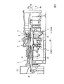
この圧縮機1は、図2に示すように、軸流圧縮機である。このため、圧縮機ロータ20は、軸線Arを中心として軸方向Daに延びているロータ軸21と、このロータ軸21の外周に固定され軸方向Daに並んでいる複数の動翼列81と、を有している。圧縮機ケーシング10の内周側には、各動翼列81の下流側の位置に静翼列11が固定されている。
As shown in FIG. 2, the compressor 1 is an axial compressor. For this reason, the
1つの静翼列11は、複数の静翼12を有している。これら複数の静翼12は、軸線Arを中心として周方向Dcに並んで、1つの静翼列11を構成する。また、1つの動翼列81は、複数の動翼82を有している。これら複数の動翼82は、軸線Arを中心として周方向Dcに並んで、1つの動翼列81を構成する。
One
静翼12は、図4に示すように、径方向Drに延びる翼体13と、翼体13の径方向Dr外側に設けられている外側シュラウド14と、翼体13の径方向Dr内側に設けられている内側シュラウド15と、を有する。外側シュラウド14は、圧縮機ケーシング10の内周側に取り付けられている。内側シュラウド15には、その径方向Dr内側にシールリング16が設けられている。動翼82は、径方向Drに延びる翼体83と、翼体83の径方向Dr内側に設けられているプラットフォーム84と、プラットフォーム84の径方向Dr内側に設けられている翼根85と、を有する。翼根85はロータ軸21に埋め込まれている。
As shown in FIG. 4, the
この圧縮機1で圧縮過程の空気が通る空気圧縮流路19は、軸線Arを中心として環状を成している。この空気圧縮流路19の外周側は、圧縮機ケーシング10及び静翼12の外側シュラウド14により画定されている。また、この空気圧縮流路19の内周側は、動翼82のプラットフォーム84及び静翼12の内側シュラウド15により画定されている。空気は、圧縮機ロータ20の回転により、この空気圧縮流路19内を圧縮されつつ上流側から下流側に流れていく。
The air
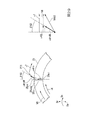
ロータ軸21には、図2に示すように、複数の動翼列81の相互間の軸方向Daにおける各位置に、言い換えると、複数の静翼列11の軸方向Daにおける各位置に、軸線Arを中心として環状を成し、径方向Drで互いに離間している複数のキャビティ23が形成されている。軸方向Daで隣接する二つの動翼列81の相互間の軸方向Daにおける位置に形成されている複数のキャビティ23は、一つのキャビティ群22を構成する。よって、ロータ軸21には、複数のキャビティ群22が軸方向Daに並んで形成されている。
As shown in FIG. 2, the
一つのキャビティ群22は、ロータ軸21内で最も径方向Dr外側に形成されている外側キャビティ24と、この外側キャビティ24よりも径方向Dr内側に形成されている中間キャビティ25と、ロータ軸21内で最も径方向Dr内側に形成されている内側キャビティ26の三つのキャビティで構成されている。
One
ロータ軸21には、さらに、外側キャビティ24と空気圧縮流路19とを連通させる径方向外側流路34と、外側キャビティ24と中間キャビティ25とを連通させる複数の径方向中間流路35と、が形成されている。径方向外側流路34は、軸線Arを中心として環状に広がる流路である。一方、複数の径方向中間流路35は、周方向Dcで互い離間している。
The
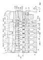
ロータ軸21は、軸方向Daで互いに積層される複数のロータディスク41と、複数のロータディスク41及び複数の中間キャビティ25を軸方向Daに貫通するスピンドルボルト51と、隣り合うロータディスク41相互の相対回転を規制する円柱状のトルクピン55と、を有する。
The
一つのロータディスク41には、一つの動翼列81が取り付けられている。よって、ロータディスク41は、複数の動翼列81毎に存在する。
One
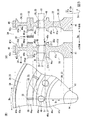
図3に示すように、一つのキャビティ群22を構成する複数のキャビティ23、このキャビティ群22の外側キャビティ24と空気圧縮流路19とを連通させる径方向外側流路34、このキャビティ群22の外側キャビティ24と中間キャビティ25とを連通させる径方向中間流路35は、いずれも、軸方向Daで隣接する二つのロータディスク41間に形成されている。なお、同図(A)は、ロータディスク41の断面図であり、同図(B)は、同図(A)におけるB矢視図である。
As shown in FIG. 3, a plurality of cavities 23 constituting one
一つのロータディスク41の上流側には、このロータディスク41の上流側の外側キャビティ24を形成するために下流側に向かって凹む上流側第一凹部43uと、このロータディスク41の上流側の中間キャビティ25を形成するために下流側に向かって凹む上流側第二凹部45uと、このロータディスク41の上流側に内側キャビティ26を形成するために下流側に向かって凹む上流側第三凹部47uと、が形成されている。よって、上流側第一凹部43uの径方向Dr外側には、上流側第一凹部43uの底面に対して、相対的に軸方向Da上流側に向かって突出する環状の上流側第一アーム部42uが形成されている。また、上流側第一凹部43uと上流側第二凹部45uとの間には、上流側第一凹部43uの底面及び上流側第二凹部45uの底面に対して、相対的に軸方向Da上流側に向かって突出する環状の上流側第二アーム部44uが形成されている。また、上流側第二凹部45uと上流側第三凹部47uとの間には、上流側第二凹部45uの底面及び上流側第三凹部47uの底面に対して、相対的に軸方向Da上流側に向かって突出する環状の上流側第三アーム部46uが形成されている。
On the upstream side of one
環状の上流側第二アーム部44uには、下流側に向かって凹んで、上流側第一凹部43uと上流側第二凹部45uとを連通させる複数の上流側ピン溝44upが形成されている。
The annular upstream
また、一つのロータディスク41の下流側には、このロータディスク41の下流側の外側キャビティ24を形成するために上流側に向かって凹む下流側第一凹部43dと、このロータディスク41の下流側の中間キャビティ25を形成するために上流側に向かって凹む下流側第二凹部45dと、このロータディスク41の下流側に内側キャビティ26を形成するために上流側に向かって凹む下流側第三凹部47dと、が形成されている。よって、下流側第一凹部43dの径方向Dr外側には、下流側第一凹部43dの底面に対して、相対的に軸方向Da下流側に向かって突出する環状の下流側第一アーム部42dが形成されている。また、下流側第一凹部43dと下流側第二凹部45dとの間には、下流側第一凹部43dの底面及び下流側第二凹部45dの底面に対して、相対的に軸方向Da下流側に向かって突出する環状の下流側第二アーム部44dが形成されている。また、下流側第二凹部45dと下流側第三凹部47dとの間には、下流側第二凹部45dの底面及び下流側第三凹部47dの底面に対して、相対的に軸方向Da下流側に向かって突出する環状の下流側第三アーム部46dが形成されている。
Further, on the downstream side of one
環状の下流側第二アーム部44dには、上流側に向かって凹んで、下流側第一凹部43dと下流側第二凹部45dとを連通させる複数の下流側ピン溝44dpが形成されている。
The annular downstream
外側キャビティ24は、軸方向Daで隣接する二つのロータディスク41のうちの上流側のロータディスク41における下流側第一凹部43dと、下流側のロータディスク41における上流側第一凹部43uとにより画定される。中間キャビティ25は、軸方向Daで隣接する二つのロータディスク41のうちの上流側のロータディスク41における下流側第二凹部45dと、下流側のロータディスク41における上流側第二凹部とにより画定される。内側キャビティ26は、軸方向Daで隣接する二つのロータディスク41のうちの上流側のロータディスク41における下流側第三凹部47dと、下流側のロータディスク41における上流側第三凹部47uとにより画定される。
The
軸方向Daで隣接する二つのロータディスク41のうちの上流側のロータディスク41における下流側第一アーム部42dと、下流側のロータディスク41における上流側第一アーム部42uとは、互いに軸方向Daで対向し且つ離間している。径方向外側流路34は、軸方向Daで隣接する二つのロータディスク41のうちの上流側のロータディスク41における下流側第一アーム部42dと、下流側のロータディスク41における上流側第一アーム部42uとにより画定される。
Of the two
軸方向Daで隣接する二つのロータディスク41のうちの上流側のロータディスク41における複数の下流側ピン溝44dpと、下流側のロータディスク41における複数の上流側ピン溝44upとは、軸方向Daで互いに対向している。トルクピン55が装着されるピン孔は、下流側ピン溝44dpと上流側ピン溝44upとにより画定される。トルクピン55が装着されるピン孔は、円柱状のトルクピン55の形状に対応して円柱状を成す。
Among the two
ロータディスク41には、上流側第二凹部45uの底面から下流側第二凹部45dの底面に貫通して、スピンドルボルト51が挿通されるボルト貫通孔48が形成されている。また、ロータディスク41の径方向Dr外側であって、上流側第一アーム部42uと下流側第二アーム部44dとの間には、動翼82の翼根85(図4参照)が装着される動翼装着部49が形成されている。
The
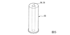
円柱状のトルクピン55には、図5に示すように、円柱の一方の端面から他方の端面に貫通する貫通孔56が形成されている。この貫通孔56は、径方向中間流路35を形成する。
As shown in FIG. 5, the
ロータ軸21で最も下流側の第一キャビティ群22と、図2に示すように、この第一キャビティ群22と軸方向Daで隣り合う上流側の第二キャビティ群22とは、一組を成す。この組では、第一キャビティ群22が下流側キャビティ群22dを成し、第二キャビティ群22が上流側キャビティ群22uを成す。第二キャビティ群22と軸方向Daで隣り合う上流側の第三キャビティ群22と、第三キャビティ群22と軸方向Daで隣り合う上流側の第四キャビティ群22とは、一組を成す。この組では、第三キャビティ群22が下流側キャビティ群22dを成し、第四キャビティ群22が上流側キャビティ群22uを成す。第四キャビティ群22と軸方向Daで隣り合う上流側の第五キャビティ群22と、第五キャビティ群22と軸方向Daで隣り合う上流側の第六キャビティ群22とは、一組を成す。この組では、第五キャビティ群22が下流側キャビティ群22dを成し、第六キャビティ群22が上流側キャビティ群22uを成す。
The
下流側キャビティ群22dの外側キャビティ24と空気圧縮流路19とを連通させる径方向外側流路34は、空気圧縮流路19中の空気を外側キャビティ24に流入させる入口流路34dを成す。また、上流側キャビティ群22uの外側キャビティ24と空気圧縮流路19とを連通させる径方向外側流路34は、外側キャビティ24内の空気を空気圧縮流路19中に流出させる出口流路34uを成す。
The radially
下流側キャビティ群22dと上流側キャビティ群22uとの間のロータディスク41には、下流側キャビティ群22dの中間キャビティ25と上流側キャビティ群22uの中間キャビティ25とを連通させる軸方向流路37が形成されている。このロータディスク41のボルト貫通孔48は、図3に示すように、ここに挿通されるスピンドルボルト51の径方向Dr内側の面との間に軸方向Daに延びる隙間48sを形成する。この隙間48sが軸方向流路37を形成する。この軸方向流路37における下流側キャビティ群22dの中間キャビティ25に対する開口は、入口開口37iを成す。また、この軸方向流路37における上流側キャビティ群22uの中間キャビティ25に対する開口は、出口開口37oを成す。この軸方向流路37における入口開口37iの径方向Dr外側縁は、下流側キャビティ群22dの中間キャビティ25の径方向Drにおける中央位置よりも径方向Dr内側に位置する。同様に、この軸方向流路37における出口開口37oの径方向Dr外側縁も、上流側キャビティ群22uの中間キャビティ25の径方向Drにおける中央位置よりも径方向Dr内側に位置する。なお、中間キャビティ25の径方向Drにおける中央位置とは、環状の中間キャビティ25を画定する内周面のうち、径方向内側内周面から径方向外側内周面までの径方向Drの高さの1/2の位置を示す。
The
このように、本実施形態では、下流側キャビティ群22dの中間キャビティ25と上流側キャビティ群22uの中間キャビティ25とを連通させる軸方向流路37が形成されている。このため、本実施形態において、下流側キャビティ群22dの中間キャビティ25と上流側キャビティ群22uの中間キャビティ25は、いずれも、軸方向連通キャビティを成す。ロータディスク41には、スピンドルボルト51が挿通される複数のボルト貫通孔48が軸線Arを中心として周方向Dcに並んで形成されている。よって、ロータディスク41には、軸方向流路37も軸線Arを中心として周方向Dcに並んで複数形成されている。
Thus, in this embodiment, the axial direction flow
次に、圧縮機ケーシング10内での空気の流れについて、図6を用いて説明する。
Next, the flow of air in the
圧縮機ケーシング10の取込口11iから供給された空気が空気圧縮流路19内に流入すると、空気は、この空気圧縮流路19内を下流側に流れつつ、次第に圧縮される。従って、空気圧縮流路19内の圧力は、下流側の方が高い。このため、一の動翼列81を基準にして下流側の空気圧縮流路19に連通する下流側キャビティ群22dの径方向外側流路34内の圧力は、この一の動翼列81を基準にして上流側の空気圧縮流路19に連通する上流側キャビティ群22uの径方向外側流路34内の圧力より高い。よって、下流側キャビティ群22dの径方向外側流路34には、空気圧縮流路19内の空気が流入する。このため、この径方向外側流路34は、前述したように、入口流路34dとして機能する。
When the air supplied from the intake port 11i of the
入口流路34d内に流入した空気は、下流側キャビティ群22dの外側キャビティ24に流入する。この空気は、トルクピン55に形成されている径方向中間流路35を経て、中間キャビティ25に流入する。中間キャビティ25に流入した空気は、ロータディスク41のボルト貫通孔48とスピンドルボルト51との間の隙間48sで形成される軸方向流路37を経て、上流側キャビティ群22uの中間キャビティ25に流入する。この空気は、トルクピン55に形成されている径方向中間流路35を経て、上流側キャビティ群22uの外側キャビティ24に流入する。外側キャビティ24に流入した空気は、上流側キャビティ群22uの外側キャビティ24と空気圧縮流路19とを連通させる径方向外側流路34から空気圧縮流路19に流出する。このため、この径方向外側流路34は、前述したように、出口流路34uとして機能する。
The air that has flowed into the
すなわち、本実施形態では、空気圧縮流路19内の軸方向Daにおける圧力差をドライビングフォースとして、空気圧縮流路19中の空気の一部がここから下流側キャビティ群22d及び上流側キャビティ群22uを経て空気圧縮流路19に戻る循環流を生じさせている。この循環流は、ロータ軸21中の各キャビティ内の換気を促進する。
In other words, in the present embodiment, the pressure difference in the axial direction Da in the
ところで、図4に示すように、動翼82の径方向外側端と、この径方向外側端と径方向Drで対向する圧縮機ケーシング10の内周面との間には、クリアランスがある。このクリアランスは、一般的にチップクリアランスCCと呼ばれ、圧縮機性能の観点から、できる限り小さいことが好ましい。
As shown in FIG. 4, there is a clearance between the radially outer end of the moving
圧縮機ロータ20、特にロータ軸21は、径方向Drの寸法が、圧縮機ケーシング10の径方向Drの厚さ寸法に比べて大きい。このため、圧縮機ロータ20は、圧縮機ケーシング10に対して熱容量が大きく、空気圧縮流路19を流れる空気の温度変化に対する熱応答性が圧縮機ケーシング10よりも低い。よって、空気圧縮流路19を流れる空気が温度変化した場合に、圧縮機ロータ20と圧縮機ケーシング10との熱応答性の差により、チップクリアランスCCに変化が生じる。
The
チップクリアランスCCの変化が大きい場合、定常クリアランスを大きくする必要がある。なお、定常クリアランスとは、ガスタービンの安定運転が継続し、且つ圧縮機ロータ20及び圧縮機ケーシング10が共に継続して同じ温度になっているときのチップクリアランスCCである。この定常クリアランスが大きいと、ガスタービンの定常運転時、動翼82の径方向外側端と圧縮機ケーシング10の内周面との間を通過する空気が多くなる。このため、定常クリアランスが大きいと、ガスタービンの定常運転時における圧縮機性能が低くなるばかりか、ガスタービン性能も低くなる。
When the change in the tip clearance CC is large, it is necessary to increase the steady clearance. The steady clearance is the tip clearance CC when the stable operation of the gas turbine is continued and both the
そこで、本実施形態では、前述したように、ロータ軸21中に空気圧縮流路19内の空気を流すことで、空気圧縮流路19を流れる空気の温度変化に対する圧縮機ロータ20の熱応答性を高め、チップクリアランスCCの変化を小さくしている。本実施形態では、このように、チップクリアランスCCの変化が小さくなるので、定常クリアランスを小さくすることができる。よって、本実施形態では、ガスタービンの定常運転時時における圧縮機性能を高めることができ、結果としてガスタービン性能を高めることができる。
Therefore, in the present embodiment, as described above, the air in the air
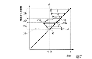
次に、図7及び図8を用いて、本実施形態において、圧縮機ロータ20の熱応答性が向上する理由について説明する。なお、図7及び図8において、横軸は空気の周速を示し、縦軸は径方向Drにおける軸線Arからの距離を示す。また、図7及び図8において、太破線はロータ軸21の周速を示し、細実線はロータ軸21内の空気の周速を示す。
Next, the reason why the thermal responsiveness of the
図7は、本実施形態におけるロータ軸21内での空気の周速変化を示す。同図に示すように、ロータ軸21は、軸線Ar上の位置での周速が0である。また、ロータ軸21は、軸線Arから遠ざかるに連れて、軸線Arからの距離に比例して周速が増加する。このため、ロータ軸21は、その外周面で最大周速Vになる。
FIG. 7 shows changes in the circumferential speed of air in the
空気圧縮流路19の空気は、図6を用いて前述したように、入口流路34dを経て下流側キャビティ群22dの外側キャビティ24に流入する。この外側キャビティ24に流入した直後の空気の周速v1は、ロータ軸21の外周面における周速Vのほぼ半分である0.5Vとすることができる。なお、ここでは、外側キャビティ24に流入した直後の空気の周速v1を0.5Vとしているが、これは一例であり、クリアランス調整等によって、この周速v1を変えることができる。外側キャビティ24に流入した空気は、外側キャビティ24内をこの外側キャビティ24に対して相対的に周方向Dcに流れつつ径方向Dr内側に流れる。この空気の周速は、角運動量保存の法則により、軸線Arからの距離に反比例して大きくなる。このため、空気が外側キャビティ24内を径方向Dr内側に流れるに連れて、この空気の周速は増加する。空気が外側キャビティ24の径方向Dr内側端に至ると、この空気の周速はv2になる。この周速v2は、外側キャビティ24に流入した直後の空気の周速v1よりも大きい。この空気は、ここで開口している複数の径方向中間流路35のうちのいずれかに流入する。径方向中間流路35に流入した空気は、径方向中間流路35内を径方向Dr内側に向かって流れて、中間キャビティ25に流入する。径方向中間流路35内の空気は、軸線Arを中心としてロータ軸21と一体に回転するため、径方向中間流路35内の空気の周速は、径方向中間流路35の周速とほぼ同じになる。
As described above with reference to FIG. 6, the air in the
なお、外側キャビティ24の径方向Dr内側端に至ったときの空気の周速v2と、径方向中間流路35における径方向外側の開口である入口開口35di(図6参照)の周速V2との間には、周速差(v2−V2)がある。このため、空気が外側キャビティ24から径方向中間流路35に流入した直後に、空気の周速が入口開口35diの周速と一致して、この周速差(v2−V2)が0になる。
Note that the peripheral speed v2 of the air when reaching the inner end in the radial direction Dr of the
空気が中間キャビティ25内に流入すると、この空気は、中間キャビティ25内をこの中間キャビティ25に対して相対的に周方向Dcに流れつつ径方向Dr内側に流れる。この中間キャビティ25内でも、空気が中間キャビティ25内を径方向Dr内側に流れるに連れて、角運動量保存の法則により、この空気の周速は増加する。このため、空気が中間キャビティ25内を径方向Dr内側に流れるに連れて、中間キャビティ25に対する周速差が大きくなる。空気が複数の軸方向流路37の入口開口37iのうち、いずれかの入口開口37iに至る直前では、この空気の周速はv3になる。この空気は、入口開口37iから軸方向流路37内に流入する。空気は、軸方向流路37内を上流側に向かって流れ、上流側キャビティ群22uの中間キャビティ25内に流入する。軸方向流路37内の空気は、軸線Arを中心としてロータ軸21と一体に回転するため、軸方向流路37内の空気の周速は、軸方向流路37の周速V3とほぼ同じになる。
When air flows into the
なお、軸方向流路37の入口開口37i(図6参照)に至る直前の空気の周速v3と、軸方向流路37の入口開口37iの周速V3との間には、周速差(v3−V3)がある。このため、空気が中間キャビティ25から軸方向流路37に流入した直後に、空気の周速が入口開口37iの周速と一致して、この周速差(v3−V3)が0になる。
Note that there is a difference in peripheral speed between the peripheral speed v3 of air immediately before reaching the
空気が上流側キャビティ群22uの中間キャビティ25内に流入すると、中間キャビティ25内をこの中間キャビティ25に対して相対的に周方向Dcに流れつつ径方向Dr外側に流れる。この中間キャビティ25内では、空気が中間キャビティ25内を径方向Dr外側に流れるに連れて、角運動量保存の法則により、この空気の周速は減少する。このため、空気が中間キャビティ25内を径方向Dr外側に流れるに連れて、中間キャビティ25に対する周速差が大きくなる。空気が中間キャビティ25の径方向Dr外側端に至ると、この空気の周速はv4aになる。空気は、ここで開口している複数の径方向中間流路35のうちのいずれかに流入する。空気は、径方向中間流路35内を径方向Dr外側に向かって流れて、上流側キャビティ群22uの外側キャビティ24に流入する。径方向中間流路35内の空気は、軸線Arを中心としてロータ軸21と一体に回転するため、径方向中間流路35内の空気の周速は、径方向中間流路35の周速V4aとほぼ同じになる。
When air flows into the
なお、中間キャビティ25の径方向Dr外側端に至ったときの空気の周速v4aと、径方向中間流路35における径方向外側の開口である入口開口35ui(図6参照)の周速V4aとの間には、周速差(v4a−V4a)がある。このため、空気が中間キャビティ25から径方向中間流路35に流入した直後に、空気の周速が入口開口35uiの周速と一致して、この周速差(v4a−V4a)が0になる。
Note that the circumferential speed v4a of the air when reaching the outer end in the radial direction Dr of the
空気が外側キャビティ24内に流入すると、この空気は、外側キャビティ24内をこの外側キャビティ24に対して相対的に周方向Dcに流れつつ径方向Dr外側に流れる。この外側キャビティ24内でも、空気が外側キャビティ24内を径方向Dr外側に流れるに連れて、角運動量保存の法則により、この空気の周速は減少する。このため、空気が外側キャビティ24内を径方向Dr外側に流れるに連れて、外側キャビティ24に対する周速差が大きくなる。
When the air flows into the
この空気は、出口流路34uを経て、空気圧縮流路19内に戻る。
This air returns to the air
このように、本実施形態では、前述したように、空気圧縮流路19内の軸方向Daにおける圧力差をドライビングフォースとして、空気圧縮流路19中の空気の一部がここから下流側キャビティ群22d及び上流側キャビティ群22uを経て空気圧縮流路19に戻る循環流を生じさせている。すなわち、本実施形態では、空気圧縮流路19内の空気の一部が、下流側キャビティ群22dの外側キャビティ24、下流側キャビティ群22dの中間キャビティ25、上流側キャビティ群22uの中間キャビティ25、上流側キャビティ群22uの外側キャビティ24内を、以上の順で流れて、空気圧縮流路19に戻る。このため、本実施形態では、ロータ軸21が回転している限り、下流側キャビティ群22dの外側キャビティ24、下流側キャビティ群22dの中間キャビティ25、上流側キャビティ群22uの中間キャビティ25、上流側キャビティ群22uの外側キャビティ24内を流れる空気の循環流により、これらのキャビティ内を換気することができる。
Thus, in the present embodiment, as described above, the pressure difference in the axial direction Da in the
また、本実施形態では、空気圧縮流路19からの空気が流れる各キャビティ23内では、空気とキャビティ23との間に周速差がある。このため、キャビティ23を画定するロータディスク41の表面の熱伝達率を高めることができる。
In the present embodiment, there is a peripheral speed difference between the air and the cavity 23 in each cavity 23 through which the air from the air
すなわち、本実施形態では、各キャビティ23内を空気圧縮流路19内を流れる空気で換気することができる。しかも、本実施形態では、ロータディスク41の壁面における熱伝達率を高めることができる。従って、本実施形態では、空気圧縮流路19を流れる空気の温度変化に対する圧縮機ロータ20の熱応答性を高めることができる。
That is, in the present embodiment, each cavity 23 can be ventilated with air flowing through the air
なお、ロータディスク41には、軸線Arを中心として周方向Dcに並んで形成されている複数の軸方向流路37の軸方向Daの中間位置で、複数の軸方向流路37を互いに連通させる周方向流路を形成してもよい。この周方向流路は、軸線Arを中心として環状に形成されている。この周方向流路を形成した場合、軸方向流路37の入口開口37iに流入した空気は、軸方向Daの上流側に向かって軸方向流路37内を流れて周方向流路に到達し、周方向流路を周方向に流れて、いずれかの軸方向流路37から上流側の中間キャビティ25に流入する。このような形態を採用しても、本実施形態と同様に圧縮機ロータ20の熱応答性を高める効果を得ることができる。
The
次に、図8及び図9を用いて、上記実施形態に対する比較例におけるロータ軸内での空気の周速変化について説明する。 Next, the change in the peripheral speed of air in the rotor shaft in the comparative example with respect to the above embodiment will be described with reference to FIGS.
本比較例は、図9に示すように、上記実施形態における下流側キャビティ群22dの中間キャビティ25と上流側キャビティ群22uの中間キャビティ25とが一体化し、一つのキャビティ23を成しているものである。ここでは、以下の説明の都合上、下流側キャビティ群22dの中間キャビティ25と上流側キャビティ群22uの中間キャビティ25とを一体化したキャビティを共有キャビティ25xとする。
In this comparative example, as shown in FIG. 9, the
本比較例では、空気圧縮流路19内の空気が、ロータ軸21内の入口流路34d、下流側キャビティ群22dの外側キャビティ24、下流側キャビティ群22dの径方向中間流路35、共有キャビティ25x、上流側キャビティ群22uの径方向中間流路35、上流側キャビティ群22uの外側キャビティ24、出口流路34uを、以上の順で流れて、空気圧縮流路19に戻る。
In this comparative example, the air in the air
空気圧縮流路19内の空気が共有キャビティ25xに至る直前までの空気の周速変化は、上記実施形態と同様である。よって、共有キャビティ25xに至る直前の空気、つまり下流側キャビティ群22dの径方向中間流路35の径方向Dr内側端における空気の周速は、この位置でのロータ軸21の周速とほぼ同じである。
The change in the peripheral speed of the air until immediately before the air in the air
下流側キャビティ群22dの径方向中間流路35から共有キャビティ25x内に流入した空気は、上流側キャビティ群22uの径方向中間流路35に流入する。共有キャビティ25xには、その下流側部分の径方向Dr外側縁に下流側キャビティ群22dの径方向中間流路35の出口開口が形成され、その上流側部分の径方向Dr外側縁に上流側キャビティ群22uの径方向中間流路35の入口開口が形成されている。一方で、この共有キャビティ25xの径方向Dr内側の領域には、流路の開口が一切形成されていない。このため、下流側キャビティ群22dの径方向中間流路35から共有キャビティ25x内に流入した空気は、共有キャビティ25x内の径方向Dr外側領域を上流側に向かって流れて、上流側キャビティ群22uの径方向中間流路35に流入する。よって、共有キャビティ25x内の径方向Dr内側領域では、空気が滞留し、空気圧縮流路19からの空気の流れがほとんどない。
The air that has flowed into the shared
上流側キャビティ群22uの径方向中間流路35に流入した空気の周速変化は、以降、上記実施形態と同様である。
The change in the peripheral speed of the air flowing into the radial
本比較例では、空気圧縮流路19内の空気が共有キャビティ25x内に流入するものの、前述したように、この空気は、共有キャビティ25x内の径方向Dr外側領域を上流側に向かって流れ、共有キャビティ25x内の径方向Dr内側領域では、空気が滞留している。このため、本比較例では、共有キャビティ25x内に径方向Dr内側領域を効果的に換気することができない。さらに、本比較例では、共有キャビティ25x内に流入した空気が、その後、共有キャビティ25x内であまり径方向Drに流れないため、径方向Drへの流れに伴う空気とキャビティ23との間の周速差がほとんど生じない。
In this comparative example, although the air in the air
そこで、上記実施形態では、本比較例の共有キャビティ25xに対応する下流側キャビティ群22dの中間キャビティ25と上流側キャビティ群22uの中間キャビティ25とを連通させる軸方向流路37における入口開口37i及び出口開口37oの位置を前述した位置に形成している。すなわち、上記実施形態では、図6に示すように、軸方向流路37における入口開口37iの径方向Dr外側縁を、下流側キャビティ群22dの中間キャビティ25の径方向Drにおける中央位置よりも径方向Dr内側に位置させると共に、この軸方向流路37における出口開口37oの径方向Dr外側縁も、上流側キャビティ群22uの中間キャビティ25の径方向Drにおける中央位置よりも径方向Dr内側に位置させている。
Therefore, in the above embodiment, the
「圧縮機の第二実施形態」
圧縮機の第二実施形態について、図10〜図13を参照して説明する。
"Second embodiment of the compressor"
A second embodiment of the compressor will be described with reference to FIGS.
上記第一実施形態における圧縮機では、下流側キャビティ群22dの中間キャビティ25と上流側キャビティ群22uの中間キャビティ25とを軸方向流路37で連通させている。本実施形態では、図10に示すように、下流側キャビティ群22dの内側キャビティ26と上流側キャビティ群22uの内側キャビティ26とを軸方向流路39で連通させている。よって、本実施形態において、下流側キャビティ群22dの内側キャビティ26と上流側キャビティ群22uの内側キャビティ26が、軸方向連通キャビティを成す。
In the compressor in the first embodiment, the
また、本実施形態のロータ軸21には、外側キャビティ24と空気圧縮流路19とを連通させる径方向外側流路34と、外側キャビティ24と中間キャビティ25とを連通させる複数の径方向中間流路35の他に、中間キャビティ25と内側キャビティ26とを連通させる複数の径方向内側流路38が形成されている。本実施形態における複数の径方向中間流路35は、上記第一実施形態における複数の径方向中間流路35と同様に、周方向Dcで互いに離間している。また、本実施形態における複数の径方向内側流路38も、上記第一実施形態における複数の径方向中間流路35と同様に、周方向Dcで互いに離間している。
Further, the
一つのキャビティ群22を構成する複数のキャビティ23、このキャビティ群22の外側キャビティ24と空気圧縮流路19とを連通させる径方向外側流路34、このキャビティ群22の外側キャビティ24と中間キャビティ25とを連通させる径方向中間流路35、さらに、このキャビティ群22の中間キャビティ25と内側キャビティ26とを連通させる径方向内側流路38は、図11に示すように、いずれも、軸方向Daで隣接する二つのロータディスク41間に形成されている。なお、同図(A)は、ロータディスク41の断面図であり、同図(B)は、同図(A)におけるB矢視図である。
A plurality of cavities 23 constituting one
一つのロータディスク41の上流側には、上記第一実施形態と同様、上流側第一アーム部42u、上流側第一凹部43u、上流側第二アーム部44u、上流側第二凹部45u、上流側第三アーム部46u、上流側第三凹部47uが形成されている。環状の上流側第二アーム部44uには、上記第一実施形態と同様、下流側に向かって凹んで、上流側第一凹部43uと上流側第二凹部45uとを連通させる複数の上流側ピン溝44upが形成されている。さらに、環状の上流側第三アーム部46uには、下流側に向かって凹んで、上流側第二凹部45uと上流側第三凹部47uとを連通させる複数の上流側流路溝46upが形成されている。
On the upstream side of one
また、一つのロータディスク41の下流側には、下流側第一アーム部42d、下流側第一凹部43d、下流側第二アーム部44d、下流側第二凹部45d、下流側第三アーム部46d、下流側第三凹部47dが形成されている。環状の下流側第二アーム部44dには、上記第一実施形態と同様、上流側に向かって凹んで、下流側第一凹部43dと下流側第二凹部45dとを連通させる複数の下流側ピン溝44dpが形成されている。さらに、環状の下流側第三アーム部46dには、上流側に向かって凹んで、下流側第二凹部45dと下流側第三凹部47dとを連通させる複数の下流側流路溝46dpが形成されている。
Further, on the downstream side of one
上記第一実施形態と同様、本実施形態でも、外側キャビティ24は、軸方向Daで隣接する二つのロータディスク41のうちの上流側のロータディスク41における下流側第一凹部43dと、下流側のロータディスク41における上流側第一凹部43uとにより画定される。中間キャビティ25は、軸方向Daで隣接する二つのロータディスク41のうちの上流側のロータディスク41における下流側第二凹部45dと、下流側のロータディスク41における上流側第二凹部45uとにより画定される。内側キャビティ26は、軸方向Daで隣接する二つのロータディスク41のうちの上流側のロータディスク41における下流側第三凹部47dと、下流側のロータディスク41における上流側第三凹部47uとにより画定される。
As in the first embodiment, also in this embodiment, the
また、径方向外側流路34は、軸方向Daで隣接する二つのロータディスク41のうちの上流側のロータディスク41における下流側第一アーム部42dと、下流側のロータディスク41における上流側第一アーム部42uとにより画定される。
Further, the radially
トルクピン55が装着されるピン孔は、下流側ピン溝44dpと上流側ピン溝44upとにより画定される。このトルクピン55には、上記第一実施形態と同様、径方向中間流路35を成す貫通孔56が形成されている。
The pin hole in which the
ロータ軸21で組を成すキャビティ群22のうち、下流側キャビティ群22dの外側キャビティ24と空気圧縮流路19とを連通させる径方向外側流路34は、空気圧縮流路19中の空気を外側キャビティ24に流入させる入口流路34dを成す。また、上流側キャビティ群22uの外側キャビティ24と空気圧縮流路19とを連通させる径方向外側流路34は、外側キャビティ24内の空気を空気圧縮流路19中に流出させる出口流路34uを成す。
Of the
下流側キャビティ群22dと上流側キャビティ群22uとの間のロータディスク41には、下流側キャビティ群22dの内側キャビティ26と上流側キャビティ群22uの内側キャビティ26とを連通させる前述の軸方向流路39が形成されている。このため、下流側キャビティ群22dと上流側キャビティ群22uとの間のロータディスク41には、第一実施形態のように、下流側キャビティ群22dの中間キャビティ25と上流側キャビティ群22uの中間キャビティ25とを連通させる軸方向流路37は形成されていない。
The above-described axial flow path that connects the
軸方向流路39における下流側キャビティ群22dの内側キャビティ26に対する開口は、入口開口39iを成す。この軸方向流路39における入口開口39iの径方向Dr外側縁は、下流側キャビティ群22dの内側キャビティ26の径方向Drにおける中央位置よりも径方向Dr内側に位置する。軸方向流路39における上流側キャビティ群22uの内側キャビティ26に対する開口は、出口開口39oを成す。この軸方向流路39における出口開口39oの径方向Dr外側縁も、同様に、上流側キャビティ群22uの内側キャビティ26の径方向Drにおける中央位置よりも径方向Dr内側に位置する。なお、内側キャビティ26の径方向Drにおける中央位置とは、環状の内側キャビティ26を画定する内周面のうち、径方向内側内周面から径方向外側内周面までの径方向Drの高さの1/2の位置を示す。
The opening of the
次に、圧縮機ケーシング10内での空気の流れについて、図12を用いて説明する。
Next, the flow of air in the
本実施形態でも、上記第一実施形態と同様、下流側キャビティ群22dの外側キャビティ24と空気圧縮流路19とを連通させる径方向外側流路34は、入口流路34dとして機能し、ここに空気圧縮流路19内の空気が流入する。
Also in the present embodiment, as in the first embodiment, the radially
本実施形態でも、上記実施形態と同様、空気圧縮流路19内の空気が、ロータ軸21内の入口流路34d、下流側キャビティ群22dの外側キャビティ24、下流側キャビティ群22dの径方向中間流路35、下流側キャビティ群22dの中間キャビティ25を、以上の順で流れる。その後、下流側キャビティ群22dの中間キャビティ25に流入した空気は、下流側キャビティ群22dの径方向内側流路38、下流側キャビティ群22dの内側キャビティ26を、以上の順で流れる。下流側キャビティ群22dの内側キャビティ26に流入した空気は、軸方向流路39を経て、上流側キャビティ群22uの内側キャビティ26に流入する。上流側キャビティ群22uの内側キャビティ26に流入した空気は、上流側キャビティ群22uの径方向内側流路38を経て、上流側キャビティ群22uの中間キャビティ25に流入する。上流側キャビティ群22uの中間キャビティ25に流入した空気は、上記実施形態と同様、上流側キャビティ群22uの径方向中間流路35、上流側キャビティ群22uの外側キャビティ24、出口流路34uを、以上の順で流れて、空気圧縮流路19に戻る。
Also in the present embodiment, as in the above embodiment, the air in the air
次に、図13を用いて、本実施形態におけるロータ軸21内での空気の周速変化について説明する。
Next, the change in the peripheral speed of air in the
空気圧縮流路19内の空気が下流側キャビティ群22dの中間キャビティ25に至るまでの、この空気の周速変化は、上記実施形態と同様である。空気が下流側キャビティ群22dの中間キャビティ25内に流入すると、中間キャビティ25内をこの中間キャビティ25に対して相対的に周方向Dcに流れつつ径方向Dr内側に流れる。この中間キャビティ25内では、空気が中間キャビティ25内を径方向Dr内側に流れるに連れて、角運動量保存の法則により、この空気の周速は増加する。このため、空気が中間キャビティ25内を径方向Dr内側に流れるに連れて、中間キャビティ25に対する周速差が大きくなる。空気が中間キャビティ25の径方向Dr内側端に至ると、空気は、ここで開口している複数の径方向内側流路38のうちのいずれかに流入する。空気は、径方向内側流路38内を径方向Dr内側に向かって流れて、下流側キャビティ群22dの内側キャビティ26に流入する。径方向内側流路38内の空気は、軸線Arを中心としてロータ軸21と一体に回転するため、径方向内側流路38内の空気の周速は、径方向内側流路38の周速とほぼ同じになる。
The change in the peripheral speed of the air until the air in the air
空気が内側キャビティ26内に流入すると、この空気は、内側キャビティ26内をこの内側キャビティ26に対して相対的に周方向Dcに流れつつ径方向Dr内側に流れる。この内側キャビティ26内でも、空気が内側キャビティ26内を径方向Dr内側に流れるに連れて、角運動量保存の法則により、この空気の周速は増加する。このため、空気が内側キャビティ26内を径方向Dr内側に流れるに連れて、内側キャビティ26に対する周速差が大きくなる。空気が複数の軸方向流路39の開口のうち、いずれかの開口に至ると、この開口から軸方向流路39内に流入する。空気は、軸方向流路39内を上流側に向かって流れ、上流側キャビティ群22uの内側キャビティ26内に流入する。軸方向流路39内の空気は、軸線Arを中心としてロータ軸21と一体に回転するため、軸方向流路39内の空気の周速は、軸方向流路39の周速とほぼ同じになる。
When air flows into the
空気が上流側キャビティ群22uの内側キャビティ26内に流入すると、内側キャビティ26内をこの内側キャビティ26に対して相対的に周方向Dcに流れつつ径方向Dr外側に流れる。この内側キャビティ26内では、空気が内側キャビティ26内を径方向Dr外側に流れるに連れて、角運動量保存の法則により、この空気の周速は減少する。このため、空気が内側キャビティ26内を径方向Dr外側に流れるに連れて、内側キャビティ26に対する周速差が大きくなる。空気が内側キャビティ26の径方向Dr外側端に至ると、空気は、ここで開口している複数の径方向内側流路38のうちのいずれかに流入する。空気は、径方向内側流路38内を径方向Dr外側に向かって流れて、上流側キャビティ群22uの中間キャビティ25に流入する。径方向内側流路38内の空気は、軸線Arを中心としてロータ軸21と一体に回転するため、径方向内側流路38内の空気の周速は、径方向内側流路38の周速とほぼ同じになる。
When air flows into the
以降、空気が、上流側キャビティ群22uの中間キャビティ25、径方向中間流路35、外側キャビティ24、出口流路34uを経て、空気圧縮流路19に戻るまでの空気の周速変化は、上記実施形態と同様である。
Thereafter, the change in the peripheral speed of the air until the air returns to the air
以上、本実施形態では、上記第一実施形態と同様、空気圧縮流路19内の軸方向Daにおける圧力差をドライビングフォースとして、空気圧縮流路19中の空気の一部が、ここから下流側キャビティ群22d及び上流側キャビティ群22uを経て空気圧縮流路19に戻る循環流を生じさせている。すなわち、本実施形態では、空気圧縮流路19内の空気の一部が、下流側キャビティ群22dの外側キャビティ24、下流側キャビティ群22dの中間キャビティ25、下流側キャビティ群22dの内側キャビティ26、上流側キャビティ群22uの内側キャビティ26、上流側キャビティ群22uの中間キャビティ25、上流側キャビティ群22uの外側キャビティ24内を、以上の順で流れて、空気圧縮流路19内に戻る。このため、本実施形態では、ロータ軸21が回転している限り、下流側キャビティ群22dの各キャビテイ内及び上流側キャビティ群22uの各キャビティ内を流れる空気の循環流により、これらのキャビティ内を換気することができる。特に、本実施形態では、下流側キャビティ群22dの内側キャビティ26、上流側キャビティ群22uの内側キャビティ26内も循環流が流れる関係で、これらキャビティ内も換気することができる。
As described above, in the present embodiment, as in the first embodiment, the pressure difference in the axial direction Da in the
また、本実施形態でも、空気圧縮流路19からの空気が流れる各キャビティ23内では、空気とキャビティ23との間に周速差がある。このため、キャビティ23を画定するロータディスク41の表面の熱伝達率を高めることができる。
Also in this embodiment, there is a peripheral speed difference between the air and the cavity 23 in each cavity 23 through which the air from the air
従って、本実施形態では、上記第一実施形態以上に、空気圧縮流路19を流れる空気の温度変化に対する圧縮機ロータ20の熱応答性を高めることができる。
Therefore, in this embodiment, the thermal responsiveness of the
「第二実施形態の第一変形例」
上記第二実施形態の第一変形例について、図14〜図22を参照して説明する。
“First Modification of Second Embodiment”
A first modification of the second embodiment will be described with reference to FIGS.
上記第一及び第二実施形態において、いずれかのキャビティ23から径方向流路又は軸方向流路に空気が流入する際、この空気と流路とに大きな周速差があると、この空気が流路内にスムーズに流入しなくなり、空気流に圧力損失が生じる。 In the first and second embodiments, when air flows into the radial flow path or the axial flow path from any of the cavities 23, if there is a large peripheral speed difference between the air and the flow path, the air is The flow does not flow smoothly into the flow path, and pressure loss occurs in the air flow.
そこで、本変形例では、空気と流路とに周速差があっても、この空気が流路内にスムーズに流入するようにして、空気流の圧力損失を低減している。このため、本変形例では、流路における入口開口を含む入口側部分は、入口開口に近づくに連れて、この入口開口に流入する空気の周方向Dcの流れの入口開口に対する相対的な向きと反対側に向かうよう、形成されている。 Therefore, in this modification, even if there is a difference in peripheral speed between the air and the flow path, this air flows smoothly into the flow path to reduce the pressure loss of the air flow. For this reason, in this modification, the inlet side portion including the inlet opening in the flow path has a relative orientation with respect to the inlet opening of the flow in the circumferential direction Dc of the air flowing into the inlet opening as it approaches the inlet opening. It is formed to go to the opposite side.
具体的に、図14及び図16に示すように、下流側キャビティ群22dの外側キャビティ24と中間キャビティ25とを連通させる径方向中間流路35dにおける径方向Dr外側の開口である入口開口35diを含む入口側部分は、入口開口35diに近づくに連れて、周方向Dcのうちロータ軸21の回転側に向くよう形成されている。なお、図14は、図11におけるXIV矢視を変形した本変形例のロータディスク41の要部矢視図である。すなわち、図14は、本変形例のロータディスク41を軸方Daの下流側から上流側に向かって見た図である。また、図16は、図14における、径方向中間流路35dの入口開口35diの位置P2周りの詳細模式図である。
Specifically, as shown in FIGS. 14 and 16, an inlet opening 35di that is an opening outside the radial direction Dr in the radial
図7を用いて前述したように、空気圧縮流路19から入口流路34dを経て下流側キャビティ群22dの外側キャビティ24に流入した直後の空気の周速v1は、ロータ軸21の外周面における周速Vのほぼ半分である0.5Vとすることができる。この空気は、外側キャビティ24内をこの外側キャビティ24に対して相対的に周方向Dcに流れつつ径方向Dr内側に流れる。この空気の周速は、角運動量保存の法則により、空気が外側キャビティ24内を径方向Dr内側に流れるに連れて増加する。よって、空気が外側キャビティ24内を径方向Dr内側に流れるに連れて、この空気の周速が径方向中間流路35dの入口開口35diの周速に近づく。しかしながら、空気が外側キャビティ24の径方向Dr内側端に至った時点でも、図7及び図14に示すように、この空気の周速v2は、径方向中間流路35dの入口開口35diの周速V2よりも遅い。
As described above with reference to FIG. 7, the peripheral speed v1 of the air immediately after flowing into the
従って、図14及び図16に示すように、この入口開口35diに流入する空気の入口開口35diに対する相対周速vr2(=v2−V2<0)の向きは、周方向Dcのうちロータ軸21の回転側とは反対側の反回転側となる。空気は、前述したように、外側キャビティ24から径方向中間流路35dに流入する過程で、相対周速vr2(=v2−V2<0)が0になるよう、その周速が増加する。そこで、ここでは、入口開口35diに対して相対的に周方向Dcの反回転側に流れる空気が、この入口開口35diで向かい受けられるようにするために、入口開口35diを含む入口側部分を、入口側開口に近づくに連れて、周方向Dcの回転側に向くよう形成している。すなわち、径方向中間流路35dの入口部分を残りの部分に対して、回転側(回転方向側)に傾き角α2で傾ける。具体的に、外側キャビティ24内の入口開口35di付近での空気の相対速度をVA2とし、この径方向成分である空気の径方向Drの相対流速をvdriとした場合、tan-1α2=vr2/vdriとすることが好ましい。この傾き角α2は、相対流速VA2のベクトルの方向と一致する。このような傾き角α2を選定すれば、単に入口側部分を傾けるよりも、空気が外側キャビティ24から径方向中間流路35dに流入する過程での圧力損失をより小さくすることができる。
Therefore, as shown in FIGS. 14 and 16, the direction of the relative circumferential speed vr2 (= v2-V2 <0) of the air flowing into the inlet opening 35di with respect to the inlet opening 35di is the direction of the
なお、前述したように、入口流路34dを経て外側キャビティ24に流入した直後の空気の流速V1は、入口流路34dの構造や圧縮機の運転条件等により、変化する。このため、入口開口35diに対する空気の相対周速vr2(=v2−V2)の向きは、ロータ軸21の回転側になる場合がある。この場合、径方向中間流路35dの入口開口35diを含む入口側部分を、所定の角度だけ回転側(回転方向側)とは逆の反回転側(反回転方向側)に傾けるのが望ましい。
As described above, the flow velocity V1 of the air immediately after flowing into the
本実施形態では、トルクピン55dにこの径方向中間流路35dを形成している。このため、この径方向中間流路35dを成すトルクピン55dの貫通孔56dは、図21に示すように、径方向Dr外側の開口である入口開口35diを含む入口側部分が、入口開口35diに近づくに連れて、周方向Dcの回転側に向くよう形成されている。
In this embodiment, the radial
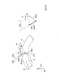
また、本変形例において、図14及び図17に示すように、下流側キャビティ群22dの中間キャビティ25と内側キャビティ26とを連通させる径方向内側流路38dにおける径方向Dr外側の開口である入口開口38diを含む入口側部分は、入口開口38diに近づくに連れて、周方向Dcのうち反回転側に向くよう形成されている。さらに、図14及び図18に示すように、軸方向流路39における下流側キャビティ群22dの内側キャビティ26に対する開口である入口開口39iを含む入口側部分は、入口開口39iに近づくに連れて、周方向Dcのうち反回転側に向くよう形成されている。なお、図17は、図14における、径方向内側流路38dの入口開口38diの位置P3周りの詳細模式図である。また、図18は、図14における、軸方向流路39の入口開口39iの位置P4周りの詳細模式図である。
In this modification, as shown in FIGS. 14 and 17, an inlet that is an opening outside the radial direction Dr in the radial
図13を用いて前述したように、空気が下流側キャビティ群22dの中間キャビティ25内を径方向Dr内側に流れるに連れて、この空気の周速は増加する。このため、この空気が中間キャビティ25の径方向Dr内側端に至った時点で、この空気の周速v3は、径方向内側流路38dの入口開口38diの周速V3よりも速い。
As described above with reference to FIG. 13, as the air flows in the radial direction Dr inside the
従って、図14及び図17に示すように、径方向内側流路38dの入口開口38diに流入する空気の入口開口38diに対する相対周速vr3(=v3−V3>0)の向きは、周方向Dcの回転側になる。空気は、前述したように、空気が中間キャビティ25から径方向内側流路38dに流入する過程で、相対周速vr3(=v3−V3>0)が0になるよう、その周速が減少する。そこで、ここでは、径方向内側流路38dの入口開口38diに対して相対的に周方向Dcの回転側に流れる空気が、この入口開口38diで向かい受けられるようにするために、この入口開口38diを含む入口側部分を、入口開口38diに近づくに連れて、周方向Dcの反回転側に向くよう形成している。すなわち、径方向内側流路38dの入口部分を残りの部分に対して、反回転側(反回転方向側)に傾き角α3で傾ける。具体的に、中間キャビティ25内の入口開口38di付近での空気の相対速度をVA3とし、この径方向成分である空気の径方向Dcの相対流速をvdriとした場合、tan−1α3=vr3/vdriとすることが好ましい。この傾き角α3は、相対流速VA3のベクトルの方向と一致する。このような傾き角α3を選定すれば、単に入口側部分を傾けるよりも、空気が中間キャビティ25から径方向内側流路38dに流入する過程での圧力損失をより小さくすることができる。
Accordingly, as shown in FIGS. 14 and 17, the direction of the relative circumferential speed vr3 (= v3-V3> 0) relative to the inlet opening 38di of the air flowing into the inlet opening 38di of the radially
また、図13を用いて前述したように、空気が下流側キャビティ群22dの内側キャビティ26内を径方向Dr内側に流れるに連れて、この空気の周速は増加する。このため、この空気が内側キャビティ26内で軸方向流路39の入口開口39iに至る直前での空気の周速v4は、軸方向流路39の入口開口39iの周速V4よりも速い。
Further, as described above with reference to FIG. 13, as the air flows in the radial direction Dr inside the
従って、図14及び図18に示すように、軸方向流路39の入口開口39iに流入する直前の空気の入口開口39iに対する相対周速vr4(=v4−V4>0)の向きは、周方向Dcの回転側になる。空気は、前述したように、空気が内側キャビティ26から軸方向流路39に流入する過程で、相対周速vr4(=v4−V4>0)が0になるよう、その周速が減少する。そこで、ここでは、軸方向流路39の入口開口39iに対して相対的に周方向Dcの回転側に流れる空気が、この入口開口39iで向かい受けられるようにするために、これらの入口開口39iを含む入口側部分を、入口開口39iに近づくに連れて、周方向Dcの反回転側に向くよう形成している。すなわち、軸方向流路39の入口部分を残りの部分に対して、反回転側(反回転方向側)に傾き角α4で傾ける。具体的に、内側キャビティ26内の入口開口39i付近での空気の相対速度をVA4とし、この軸方向成分である空気の軸方向Daの相対流速をvdaとした場合、tan-1α4=vr4/vdaとすることが好ましい。この傾き角α4は、相対流速VA4のベクトルの方向と一致する。このような傾き角α4を選定すれば、単に入口側部分を傾けるよりも、空気が内側キャビティ26から軸方向流路39に流入する過程での圧力損失をより小さくすることができる。
Therefore, as shown in FIGS. 14 and 18 , the direction of the relative peripheral speed vr4 (= v4-V4> 0) relative to the
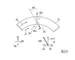
また、本変形例において、図15及び図19に示すように、上流側キャビティ群22uの内側キャビティ26と中間キャビティ25とを連通させる径方向内側流路38uにおける径方向Dr内側の開口である入口開口38uiを含む入口側部分は、入口開口38uiに近づくに連れて、周方向Dcのうち回転側に向くよう形成されている。さらに、図15及び図20に示すように、上流側キャビティ群22uの中間キャビティ25と外側キャビティ24とを連通させる径方向中間流路35uにおける径方向Dr内側の開口である入口開口35uiを含む入口側部分も、入口開口35uiに近づくに連れて、周方向Dcのうち回転側に向くよう形成されている。なお、図15は、図11におけるXV矢視を変形した本変形例のロータディスク41の要部矢視図である。すなわち、図15は、本変形例のロータディスク41を軸方Daの上流側から下流側に向かって見た図である。従って、図14に描かれている周方向Dcの回転側に対して、図15に描かれている周方向Dcの回転側が逆側になる。また、図19は、図15における、径方向内側流路38uの入口開口38uiの位置P5周りの詳細模式図である。図20は、図15における、径方向中間流路35uの入口開口35uiの位置P6周りの詳細模式図である。
In this modification, as shown in FIGS. 15 and 19, an inlet that is an opening inside the radial direction Dr in the radial
図13を用いて前述したように、空気が上流側キャビティ群22uの内側キャビティ26内を径方向Dr外側に流れるに連れて、この空気の周速は減少する。このため、この空気が内側キャビティ26の径方向Dr外側端に至った時点で、この空気の周速v5は、径方向内側流路38uの入口開口38uiの周速V5よりも遅い。
As described above with reference to FIG. 13, as the air flows inside the
従って、図15及び図19に示すように、上流側キャビティ群22uにおける径方向内側流路38uの入口開口38uiに流入する空気の入口開口38uiに対する相対周速vr5(=v5−V5<0)の向きは、周方向Dcの反回転側である。空気は、前述したように、内側キャビティ26から径方向内側流路38uに流入する過程で、相対周速vr5(=v5−V5<0)が0になるよう、その周速が増加する。そこで、ここでは、径方向内側流路38uの入口開口38uiに対して相対的に周方向Dcの反回転側に流れる空気が、これらの入口開口38uiで向かい受けられるようにするため、これらの入口開口38uiを含む入口側部分を、入口開口38uiに近づくに連れて、周方向Dcの回転側に向くよう形成している。すなわち、径方向内側流路38uの入口部分を残りの部分に対して、回転側(回転方向側)に傾き角α5だけ傾ける。具体的に、内側キャビティ26内の入口開口38ui付近での空気の相対速度をVA5とし、この径方向成分である空気の径方向Dcの相対流速をvdroとした場合、tan-1α5=vr5/vdroとすることが好ましい。この傾き角α5は、相対流速VA5のベクトルの方向と一致する。このような傾き角α5を選定すれば、単に入口側部分を傾けるよりも、空気が内側キャビティ26から径方向内側流路38uに流入する過程での圧力損失をより小さくすることができる。
Therefore, as shown in FIGS. 15 and 19, the relative peripheral speed vr5 (= v5-V5 <0) of the air flowing into the inlet opening 38ui of the radially
また、図13を用いて前述したように、空気が上流側キャビティ群22uの中間キャビティ25を径方向Dr外側に流れるに連れて、この空気の周速も減少する。このため、この空気が中間キャビティ25の径方向Dr外側端に至った時点で、この空気の周速v6は、径方向中間流路35uの入口開口35uiの周速V6よりも遅い。
As described above with reference to FIG. 13, as the air flows through the
従って、図15及び図20に示すように、上流側キャビティ群22uにおける径方向中間流路35uの入口開口35uiに流入する空気の入口開口35uiに対する相対周速vr6(=v6−V6<0)の向きは、周方向Dcの反回転側である。空気は、前述したように、中間キャビティ25から径方向中間流路35uに流入する過程で、相対周速vr6(=v6−V6)が0になるよう、その周速が増加する。そこで、ここでは、径方向中間流路35uの入口開口35uiに対して相対的に周方向Dcの反回転側に流れる空気が、この入口開口35uiで向かい受けられるようにするため、これらの入口開口35uiを含む入口側部分を、入口開口35uiに近づくに連れて、周方向Dcの回転側に向くよう形成している。すなわち、径方向中間流路35uの入口部分を残りの部分に対して、回転側(回転方向側)に傾き角α6だけ傾ける。具体的に、中間キャビティ25内の入口開口35ui付近での空気の相対速度をVA6とし、この径方向成分である空気の径方向Dcの相対流速をvdroとした場合、tan-1α6=vr6/vdroとすることが好ましい。この傾き角α6は、相対流速VA6のベクトルの方向と一致する。このような傾き角α6を選定すれば、単に入口側部分を傾けるよりも、空気が中間キャビティ25から径方向中間流路35uに流入する過程での圧力損失をより小さくすることができる。
Accordingly, as shown in FIGS. 15 and 20, the relative peripheral speed vr6 (= v6-V6 <0) of the air flowing into the inlet opening 35ui of the radial
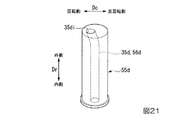
本実施形態では、トルクピン55uにこの径方向中間流路35uを形成している。このため、この径方向中間流路35uを成すトルクピン55uの貫通孔56uは、図22に示すように、径方向Dr内側の開口である入口開口35uiを含む入口側部分が、入口開口35uiに近づくに連れて、周方向Dcの回転側に向くよう形成されている。
In the present embodiment, the radial
なお、本変形例は、第二実施形態の第一変形例であるが、第一実施形態においても同様に変形してもよい。 In addition, although this modification is a 1st modification of 2nd embodiment, you may deform | transform similarly also in 1st embodiment.
「第二実施形態の第二変形例」
次に、上記第二実施形態の第二変形例について、図23〜図29を参照して説明する。
“Second Modification of Second Embodiment”
Next, a second modification of the second embodiment will be described with reference to FIGS.
本変形例は、径方向流路又は軸方向流路の出口部分に、ロータ軸21の回転方向側、又回転方向側に対して反対側の反回転側に向けて傾きを与えた例である。前述した第一変形例に示す下流側キャビティ群22dの径方向流路と上流側キャビティ群22uの径方向流路及び軸方向流路の各流路の出口部分は、回転方向に対して傾くことなく、径方向Dr又は軸方向Daに一致する方向に開口する例である。しかしながら、これらの出口部分を回転方向側に又は回転方向側に対して反対側(反回転側)に傾けてもよい。
This modification is an example in which the outlet portion of the radial flow path or the axial flow path is inclined toward the rotation direction side of the
図23は、下流側キャビティ群22dの径方向中間流路35dの径方向内側の出口開口35doを含む出口側部分35dopを、回転方向側に傾けた例を示す。また、図24は、径方向中間流路35dの出口開口35doを含む出口側部分35dopを、回転方向側に対して反対側の反回転側に傾けた例を示す。なお、図23及び図24は、図14における径方向中間流路35dの出口開口35doの位置P7周りの詳細模式図である。
FIG. 23 shows an example in which the outlet side portion 35dop including the outlet opening 35do on the radially inner side of the radial direction
図23に示すように、径方向中間流路35dの出口側部分35dopを径方向中間流路35dの残りの部分に対して回転方向側に傾き角β21で傾けた場合、径方向中間流路35d内の中間部を流れる空気は、周速V2、径方向速度vdriで流れる。径方向中間流路35dの出口側部分35dopを、回転方向側に傾き角β21で傾けることにより、傾けた後の出口側部分35dopにおける軸方向速度(出口側部分35dopにおける流路の軸方向速度)は、vdriLになる。この出口側部分35dopの軸方向速度vdriLの周方向Dcの速度成分(相対周速)vr21が、空気の周速V2に付加される。すなわち、径方向中間流路35dの出口側部分35dopにおいて、空気の周速V3は、(V2+vr21)となる。つまり、出口側部分35dopから中間キャビティ25(軸方向連通キャビティ)に流入した直後の空気は、中間キャビティ25との相対周速差vr21だけ速い周速V3で径方向Dr内側に向かって流れる。空気の周速は、角運動量保存の法則により、空気が中間キャビティ25内を径方向Dr内側に流れるに連れて増加する。つまり、空気が径方向Dr内側方向に流れるに連れて、中間キャビティ25との間の周速差が拡大して、空気が径方向内側流路38dに流入する際の圧力損失は増加するものの、空気と中間キャビティ25との間の熱伝達率が高まり、熱伝達が促進される。
As shown in FIG. 23, when the outlet side portion 35dop of the radial
一方、図24に示すように、径方向中間流路35dの出口側部分35dopを径方向中間流路35dの残りの部分に対して反回転側に傾き角β22で傾けた場合、径方向中間流路35d内の中間部を流れる空気は、周速V2、径方向速度vdriで流れる。径方向中間流路35dの径方向Dr内側の出口側部分35dopを回転方向側に対して逆方向の反回転側に傾き角β22で傾けることにより、傾けた後の出口側部分35dopにおける軸方向速度(出口側部分35dopにおける流路の軸方向速度)は、vdriMになる。出口側部分35dopにおいて、この出口側部分35dopの軸方向速度vdriMの周方向Dcの速度成分(相対周速)vr22だけ、空気の周速は減少する。すなわち、径方向中間流路35dの出口側部分35dopにおいて、空気の周速V3は、(V2-vr22)となる。つまり、出口側部分35dopから中間キャビティ25(軸方向連通キャビティ)に流入した直後の空気は、径方向中間流路35d内の空気の周速V2に対して中間キャビティ25との相対周速差vr22だけ小さい周速で、径方向Dr内側に向かって流れる。空気の周速は、角運動量保存の法則により、空気が中間キャビティ25を径方向Dr内側に流れるに連れて増加する。一方、中間キャビティ25の周速は、径方向Dr内側に向かうに連れて小さくなる。従って、空気が、中間キャビティ25を径方向Dr内側に向かって流れる過程で、空気と中間キャビティ25との周速差が次第に小さくなる。空気と中間キャビティ25との間の周速差が小さくなり、中間キャビティ25との間の熱伝達率は低下する。一方で、中間キャビティ25から空気が流入する径方向内側流路38dの入口開口38diにおいて、上述の中間キャビティ25と空気との周速差が小さくなる位置を選定すれば、中間キャビティ25から径方向内側流路38dの入口開口38diに流入する際の圧力損失を大幅に低減できる。
On the other hand, as shown in FIG. 24, when the outlet side portion 35dop of the radial
図23では、径方向内側流路38dの出口開口38doを含む出口側部分38dopを径方向内側流路38dの残りの部分に対して回転方向側に傾き角β31で傾けた例も示す。なお、図23では、径方向内側流路38dに関する各符号に関しては、()内に記している。また、図23の()内の部分は、図14における径方向内側流路38dの出口開口38doの位置P8周りの詳細模式図である。径方向内側流路38dから内側キャビティ26に流入する空気の周速の考え方は、径方向中間流路35dを流れる空気流と同じである。また、径方向内側流路38dから内側キャビティ26に流入した空気が、径方向Dr内側方向に流れる過程で、空気と内側キャビティ26との間の周速差が拡大し、熱伝達率が高まる効果も、径方向中間流路35dから中間キャビティ25に流入する空気流と同様である。
FIG. 23 also shows an example in which the outlet side portion 38dop including the outlet opening 38do of the radially
図24では、径方向内側流路38dの出口側部分38dopを径方向内側流路38dの残りの部分に対して反回転方向側に傾き角β32で傾けた例も示す。なお、図24では、径方向内側流路38dに関する各符号に関しては、()内に記している。また、図24の()内の部分は、図14における径方向内側流路38dの出口開口38doの位置P8周りの詳細模式図である。この場合における径方向内側流路38dから内側キャビティ26に流入する空気の周速の考え方は、径方向中間流路35dを流れる空気流と同じである。また、空気が軸方向流路39へ流入する際の周速の変化による圧力損失の低減効果も、径方向中間流路35dから中間キャビティ25に流入する空気流と同様である。
FIG. 24 also shows an example in which the outlet side portion 38dop of the radially
図25は、下流側キャビティ群22dの軸方向流路39の上流側(軸方向Daの上流側)の出口開口39oを含む出口側部分39opを、軸方向流路39の残りの部分に対して回転方向側に傾けた例を示す。また、図26は、軸方向流路39の出口側部分39opを回転方向側に対して反対側の反回転側に傾けた例を示す。なお、図25及び図26は、図15における軸方向流路39の出口開口39oの位置P9周りの詳細模式図である。
FIG. 25 shows an outlet side portion 39op including an outlet opening 39o on the upstream side (upstream side in the axial direction Da) of the
図25に示すように、軸方向流路39の出口側部分39opを軸方向流路39の残りの部分に対して回転方向側に傾き角β41で傾けた場合、軸方向流路39内の中間部を流れる空気は、周速V4、軸方向速度(軸方向Daの流路内速度)vdaで流れる。軸方向流路39の出口側部分39opを回転方向側に傾き角β41で傾けることにより、傾けた後の出口側部分39opにおける空気の軸方向速度(出口側部分35dopにおける流路内の流路方向速度)は、vdaLになる。この出口側部分39opの軸方向速度vdaLの周方向Dcの速度成分(相対周速)vr41が、空気の周速V4に付加される。すなわち、軸方向流路39の出口側部分39opにおいて、空気の周速V5は、(V4+vr41)となる。つまり、出口側部分39opから内側キャビティ26に流入した直後の空気は、内側キャビティ26との相対周速差vr41だけ速い周速V5で内側キャビティ26内を径方向Dr外側に向かって流れる。空気の周速は、角運動量保存の法則により、空気が内側キャビティ26を径方向Dr外側に流れるに連れて次第に小さくなる。一方、内側キャビティ26の周速は、径方向Dr外側に向かうに連れて大きくなる。従って、空気が、内側キャビティ26を径方向Dr外側に向かって流れる過程で、空気と内側キャビティ26の周速差が次第に小さくなる。空気と内側キャビティ26との間の周速差が小さくなることにより、内側キャビティ26との間の熱伝達率は低下する。一方で、内側キャビティ26から空気が流入する径方向内側流路38uの入口開口38uiにおいて、上述の内側キャビティ26と空気との周速差が小さくなる径方向内側流路38dの位置を選定すれば、内側キャビティ26から径方向内側流路38uの入口開口38uiに流入する際の圧力損失を大幅に低減できる。
As shown in FIG. 25, when the outlet side portion 39op of the
一方、図26に示すように、軸方向流路39の出口側部分39opを軸方向流路39の残りの部分に対して反回転側に傾き角β42で傾けた場合、軸方向流路39内の中間部を流れる空気は、周速V4、軸方向速度(軸方向Daの流路内速度)vdaで流れる。軸方向流路39の出口側部分39opを反回転側に傾き角β42で傾けることにより、傾けた後の出口側部分39opにおける空気の軸方向速度(出口側部分39opにおける流路内の流路方向速度)は、vdaMになる。この出口側部分35opの軸方向速度vdaMの周方向Dcの速度成分(相対周速)vr42だけ、空気の周速は減少する。すなわち、軸方向流路39の出口側部分39opにおいて、空気の周速V5は、(V4−vr42)となる。つまり、軸方向流路39の出口側部分39opから内側キャビティ26に流入した直後の空気は、軸方向流路39内の空気の周速V4に対して内側キャビティ26との相対周速差vr42だけ小さい周速で、内側キャビティ26内を径方向Dr外側に向かって流れる。空気の周速は、角運動量保存の法則により、空気が内側キャビティ26内を径方向Dr外側に流れるに連れて小さくなる。一方、内側キャビティ26の周速は、径方向Dr外側に向かうに連れて大きくなる。つまり、空気が、内側キャビティ26を径方向Dr外側に流れるに連れて、空気と内側キャビティ26との周速差が拡大する。すなわち、空気が径方向Dr外側に流れるに連れて、空気と内側キャビティ26との間の周速差が拡大して、空気が径方向内側流路38uに流入する際の圧力損失は増加するものの、内側キャビティ26との間の熱伝達率が高まり、熱伝達が促進される。
On the other hand, as shown in FIG. 26, when the outlet side portion 39op of the
図27は、上流側キャビティ群22uにおける径方向内側流路38uの出口開口38uoを含む出口側部分38uopを、径方向内側流路38uの残りの部分に対して回転方向側に傾けた例を示す。また、図28は、径方向内側流路38uの出口側部分38uopを、径方向内側流路38uの残りの部分に対して回転方向側と反対側の反回転側に傾けた例を示す。なお、図27及び図28は、図15における径方向内側流路38uの出口開口38uoの位置P10周りの詳細模式図である。
FIG. 27 shows an example in which the outlet side portion 38uop including the outlet opening 38uo of the radially
図27に示すように、径方向内側流路38uの出口側部分38uopを径方向内側流路38uの残りの部分に対して回転方向側に傾き角β51で傾けた場合、径方向内側流路38u内の中間部を流れる空気は、周速V5、径方向速度vdroで流れる。径方向内側流路38uの出口側部分38uopを回転方向側に傾き角β51で傾けることにより、傾けた後の出口側部分38uopにおける空気の軸方向速度(出口側部分38uopにおける流路内の流路方向速度)は、vdroMになる。この出口側部分38uopの軸方向速度vdroMの周方向Dcの速度成分(相対周速)vr51が、空気の周速V5に付加される。すなわち、径方向内側流路38uの出口側部分38uopにおいて、空気の周速V6は、(V5+vr51)となる。つまり、出口側部分38uopから中間キャビティ25(軸方向連通キャビティ)に流入した直後の空気は、中間キャビティ25との相対周速差vr51だけ速い周速V6で径方向Dr外側に向かって流れる。空気の周速は、角運動量保存の法則により、空気が中間キャビティ25内を径方向Dr外側に流れるに連れて小さくなる。一方、中間キャビティ25の周速は、径方向Dr外側に向かうに連れて大きくなる。従って、空気が、中間キャビティ25を径方向Dr外側に向かって流れる過程で、空気と中間キャビティ25との周速差が次第に小さくなる。空気と中間キャビティ25との間の周速差が小さくなることにより、中間キャビティ25との間の熱伝達率は低下する。一方で、中間キャビティ25から空気が流入する径方向中間流路35uの入口開口35uiにおいて、上述の中間キャビティ25と空気との周速差が小さくなる径方向中間流路35uの位置を選定すれば、中間キャビティ25から径方向中間流路35uの入口開口35uiに流入する際の圧力損失を大幅に低減できる。
As shown in FIG. 27, when the
一方、図28に示すように、径方向内側流路38uの出口側部分38uopを径方向内側流路38uの残りの部分に対して反回転側に傾き角β52で傾けた場合、径方向内側流路38u内の中間部を流れる空気は、周速V5、径方向速度vdroで流れる。径方向内側流路38uの出口側部分38uopを傾き角β52で傾けることにより、傾けた後の出口側部分38uopにおける空気の軸方向速度(出口側部分38uopにおける流路内の流路方向速度)は、vdroMになる。この出口側部分38uopの軸方向速度vdroMの周方向Dcの速度成分(相対周速)vr52だけ、空気の周速は減少する。すなわち、径方向内側流路38uの出口側部分38uopにおいて、空気の周速V6は、(V5-vr52)となる。つまり、径方向内側流路38uの出口側部分38uopから中間キャビティ25に流入した直後の空気は、径方向内側流路38u内の空気の周速V5に対して中間キャビティ25との相対周速差vr52だけ小さい周速V6で、内側キャビティ26内を径方向Dr外側に向かって流れる。空気の周速は、角運動量保存の法則により、空気が中間キャビティ25内を径方向Dr外側に流れるに連れて小さくなる。一方、中間キャビティ25の周速は、径方向Dr外側に向かうに連れて大きくなる。つまり、空気が、中間キャビティ25を径方向Dr外側に流れるに連れて、空気と中間キャビティ25との周速差が拡大する。すなわち、空気が中間キャビティ25内を径方向Dr外側に流れるに連れて、空気と中間キャビティ25との間の周速差が拡大して、空気が径方向中間流路35uに流入する際の圧力損失は増加するものの、中間キャビティ25との間の熱伝達率が高まり、熱伝達が促進される。
On the other hand, as shown in FIG. 28, when the
図29は、上流側キャビティ群22uにおける径方向中間流路35uの出口開口35uoを含む出口側部分35uopを、径方向中間流路35uの残りの部分に対して回転方向側に傾けた例を示す。なお、図29は、図15における径方向中間流路35uの出口開口35uoの位置P11周りの詳細模式図である。
FIG. 29 shows an example in which the outlet side portion 35uop including the outlet opening 35uo of the radial
図29に示すように、径方向中間流路35uの出口側部分35uopを径方向中間流路35uの残りの部分に対して反回転側に傾き角β62で傾けた場合、径方向内側流路38u内の中間部を流れる空気は、周速V6、径方向速度vdroで流れる。径方向中間流路35uの出口側部分35uopで、回転方向側に対して逆方向の反回転側に傾き角β62で傾けることにより、傾けた後の出口側部分35uopにおける空気の軸方向速度(出口側部分35uopにおける流路内の流路方向速度)は、vdroMになる。この出口側部分35uopの軸方向速度vdroMの周方向Dcの速度成分(相対周速)vr62だけ、空気の周速は減少する。すなわち、径方向中間流路35uの出口側部分35uopにおいて、空気の周速V7は、(V6−vr62)となる。つまり、径方向中間流路35uの出口側部分35uopから外側キャビティ24に流入した直後の空気は、径方向中間流路35u内の空気の周速V6に対して外側キャビティ24との相対周速差vr62だけ小さい周速V7で、外側キャビティ24内を径方向Dr外側に向かって流れる。空気の周速は、角運動量保存の法則により、空気が外側キャビティ24内を径方向Dr外側に流れるに連れて小さくなる。一方、外側キャビティ24の周速は、径方向Dr外側に向かうに連れて大きくなる。つまり、空気が、外側キャビティ24内を径方向Dr外側に流れるに連れて、空気と外側キャビティ24との周速差が拡大する。すなわち、空気が外側キャビティ24内を径方向Dr外側に流れるに連れて、空気と外側キャビティ24との間の周速差が拡大して、外側キャビティ24との間の熱伝達率が高まり、熱伝達が促進される。
As shown in FIG. 29, when the
上述のように、径方向流路の出口部分を回転方向に対して傾ける方向(回転方向側又は反回転方向側)により生ずる効果が、上流側キャビティ群22uと下流側キャビティ群22dでは異なっている。
すなわち、下流側キャビティ群22dの径方向中間流路35dの出口側部分35dop又は径方向内側流路38dの出口側部分38dopを回転方向側に傾けた場合は、空気と中間キャビティ25又は内側キャビティ26との周速差が拡大する。このため、この場合、空気と中間キャビティ25又は内側キャビティ26との間で、熱伝達の促進が図られ、中間キャビティ25又は内側キャビティ26の熱応答性を改善することができる。
As described above, the upstream
That is, when the outlet side portion 35dop of the radial
また、下流側キャビティ群22dの径方向中間流路35dの出口側部分35dop又は径方向内側流路38dの出口側部分38dopを反回転側に傾けた場合は、空気と中間キャビティ25又は内側キャビティ26との周速差が小さくなる。このため、この場合、中間キャビティ25から径方向内側流路38dの入口開口38do又は内側キャビティ26から軸方向流路39の入口開口39iに流入する際の圧力損失を大幅に低減できる。
Further, when the outlet side portion 35dop of the radial
一方、上流側キャビティ群22uの径方向内側流路38uの出口側部分38uop又は軸方向流路39の出口側部分39opを、回転方向側に傾けた場合は、空気と中間キャビティ25又は空気と内側キャビティ26との周速差が小さくなる。このため、この場合、中間キャビティ25から径方向中間流路35uの入口開口35ui又は内側キャビティ26から径方向内側流路38uの入口開口38uiに流入する際の圧力損失を大幅に低減できる。
On the other hand, when the outlet side portion 38op of the radially
また、上流側キャビティ群22uの径方向中間流路35uの出口側部分35uop又は径方向内側流路38uの出口側部分38uop又は軸方向流路39の出口側部分39opを、反回転側に傾けた場合は、空気と外側キャビティ24又は空気と中間キャビティ25又は空気と内側キャビティ26との周速差が拡大する。このため、この場合、空気と外側キャビティ24又は中間キャビティ25又は内側キャビティ26との間で、熱伝達の促進が図られ、外側キャビティ24又は中間キャビティ25又は内側キャビティ26の熱応答性を改善することができる。
Further, the outlet side portion 35uop of the radial
すなわち、上流側キャビティ群22u及び下流側キャビティ群22dの径方向流路(径方向中間流路35d、35u、径方向内側流路38d、38u)及び軸方向流路37、39の入口側部分又は出口側部分に関して、回転方向に対して傾ける方向及び傾き角の選定は、圧縮機の性能及び構造を考慮して、熱応答性が最も高くなる組合せを適宜選定可能である。
That is, the inlet side portions of the radial flow paths (the radial
なお、本変形例は、第二実施形態の第二変形例であるが、第一実施形態においても同様に変形してもよい。また、第一変形例と第二変形例を適宜組み合わせてもよい。 In addition, although this modification is a 2nd modification of 2nd embodiment, you may deform | transform similarly also in 1st embodiment. Moreover, you may combine a 1st modification and a 2nd modification suitably.
「第二実施形態の第三変形例」
図30及び図31に示すように、径方向流路(径方向中間流路35d,35u、径方向内側流路38d,38u)又は軸方向流路37,39の入口側部分を、入口開口から出口開口に進むに連れて流路内径が小さくように形成してもよい。具体的に、図30は、入口形状がベルマウス状を成し、これらの流路の長手方向に平行な断面で見た場合、入口流路を画定する面が曲面状に形成された斜面40iである。また、図31は、入口形状が漏斗状を成し、これらの流路の長手方向に平行な断面で見た場合、入口形状を画定する面が直線状の傾きで形成された斜面40iである。このような入口形状であれば、空気が流路に流入する際、空気流の乱れが発生せず、圧力損失の低減ができる。
“Third Modification of Second Embodiment”
As shown in FIGS. 30 and 31 , the inlet-side portion of the radial flow path (the radial
なお、本変形例は、第二実施形態の第三変形例であるが、第一実施形態においても同様に変形してもよい。また、第一変形例と第二変形例と第三変形例を適宜組み合わせてもよい。 In addition, although this modification is a 3rd modification of 2nd embodiment, you may deform | transform similarly also in 1st embodiment. Moreover, you may combine a 1st modification, a 2nd modification, and a 3rd modification suitably.
「第一実施形態の他の変形例」
上記第一実施形態の他の変形例について、図32を参照して説明する。
"Other variations of the first embodiment"
Another modification of the first embodiment will be described with reference to FIG.
上記第一及び第二実施形態では、軸方向Daで隣り合う二つのキャビティ群22を一組としている。しかしながら、軸方向Daで隣り合う3以上のキャビティ群22を一組としてもよい。
In the first and second embodiments, two
例えば、軸方向Daで隣り合う3つのキャビティ群22を一組とする場合、図32に示すように、この組を構成する3つのキャビティ群22のうち、最も上流側のキャビティ群22を上流側キャビティ群22uとし、残りの2つのキャビティ群22を下流側キャビティ群22dとしてもよい。
For example, when three
この場合、二つの下流側キャビティ群22dのうち、下流側の第一下流側キャビティ群22d1と上流側の第二下流側キャビティ群22d2とにおける中間キャビティ(軸方向連通キャビティ)25相互を軸方向流路37で連通させると共に、第二下流側キャビティ群22d2と上流側キャビティ群22uとにおける中間キャビティ(軸方向連通キャビティ)25相互を軸方向流路37で連通させる。
In this case, out of the two
また、軸方向Daで隣り合う4つのキャビティ群22を一組とする場合には、この組を構成する4つのキャビティ群22のうち、最も上流側のキャビティ群22を上流側キャビティ群とし、残りの3つのキャビティ群22を下流側キャビティ群としてもよい。また、この組を構成する4つのキャビティ群22のうち、上流側の2つのキャビティ群22を上流側キャビティ群とし、残りの2つのキャビティ群22を下流側キャビティ群としてもよい。
In addition, when four
以上のように、軸方向Daで隣り合う3以上のキャビティ群22を一組とする場合、例えば、最も下流側のキャビティ群22と、これに軸方向Daで隣接するキャビティ群22とにおける軸方向連通キャビティ相互を連通させる軸方向流路37では、この中を空気が上流側に流れなければ、空気圧縮流路19からの空気がこの空気圧縮流路19に戻らない。そこで、この軸方向流路37を含む各流路における流路抵抗を適宜定めて、この軸方向流路37内を空気が上流側に流れるようにする必要がある。
As described above, when a set of three or
なお、本変形例は、上記第一実施形態の変形例であるが、上記第二実施形態やその変形例に適用してもよい。 The present modification is a modification of the first embodiment, but may be applied to the second embodiment or a modification thereof.
「その他の変形例」
以上の各実施形態及び各変形例では、いずれも、ロータ軸21で最も下流側の第一キャビティ群22から上流側の第六キャビティ群22までのキャビティ群22を本発明の適用対象にしている。しかしながら、ロータ軸21で最も下流側の第一キャビティ群22から、例えば、上流側の第八キャビティ群22までのキャビティ群22を本発明の適用対象にしてもよいし、最も下流側の第一キャビティ群22から上流側の全キャビティ群22を本発明の適用対象にしてもよい。また、例えば、ロータ軸21で最も下流側の第一キャビティ群22から上流側の第四キャビティ群22までのキャビティ群22を本発明の適用対象にしてもよいし、ロータ軸21で最も下流側の第一キャビティ群22から上流側の第二キャビティ群22までのキャビティ群22を本発明の適用対象にしてもよい。
"Other variations"
In each of the above embodiments and modifications, the
すなわち、軸方向Daで隣接する複数のキャビティ群22であって、ロータ軸21中で最も下流側の第一キャビティ群22を含む複数のキャビティ群22であれば、本発明の適用対象にすることができる。このように、本発明の適用対象として、ロータ軸21中で最も下流側に第一キャビティ群22を含めている。これは、空気圧縮流路19中で、この第一キャビティ群22が存在する軸方向Daの位置での圧力が他の位置に比べて圧力が高くなり、ロータ軸21中でこの位置での温度変化が他の位置に比べて大きいからである。
That is, a plurality of
また、以上の各実施形態及び各変形例は、いずれもガスタービンの圧縮機であるが、本発明はこれに限定されない。このため、本発明において、圧縮機に流入する気体は、空気に限らない。 Further, each of the above embodiments and modifications is a compressor of a gas turbine, but the present invention is not limited to this. For this reason, in this invention, the gas which flows in into a compressor is not restricted to air.
なお、以上の各実施形態及び各変形例では、いずれも圧縮機1の空気圧縮流路19を流れる圧縮過程の空気の一部をロータ軸21内に導き、ロータ軸21の各キャビティ内をこの空気で換気している。この方法に対して、圧縮機1の空気圧縮流路19から流出し、ガスタービンケーシング9内に存在する出口空気をロータ軸21内に導き、ロータ軸21の各キャビティ内をこの空気で換気する方法も考えられる。しかしながら、この方法では、目的の圧力にまで高まって空気圧縮流路19から流出して空気をロータ軸21の各キャビティ内の換気に利用するため、換気に利用する空気の圧力を高めるために利用させるエネルギーが以上の各実施形態及び各変形例よりも大きくなる。しかも、換気に利用する空気の温度が、ロータ軸21中で静翼列11が設けられている部分の温度より高いため、以上の各実施形態及び各変形例よりも換気効果が小さい。よって、繰り返すことになるが、以上の各実施形態及び各変形例のように、圧縮機1の空気圧縮流路19を流れる圧縮過程の空気の一部をロータ軸21内に導き、ロータ軸21の各キャビティ内をこの空気で換気することが好ましい。
In each of the above embodiments and modifications, a part of the air in the compression process that flows through the air
1:圧縮機、2:燃焼器、3:タービン、10:圧縮機ケーシング、11:静翼列、12:静翼、19:空気圧縮流路(気体圧縮流路)、20:圧縮機ロータ、21:ロータ軸、22:キャビティ群、22d:下流側キャビティ群、22u:上流側キャビティ群、23:キャビティ、24:外側キャビティ、25:中間キャビティ(軸方向連通キャビティ)、26:内側キャビティ(軸方向連通キャビティ)、34:径方向外側流路、34d:入口流路、34u:出口流路、35,35d,35u:径方向中間流路、35di,35ui,37i,39i:入口開口、37,37a:軸方向流路、35do,37o,38do,38uo,39o:出口開口、35dop,38dop,38uop,39op:出口側部分、38:径方向内側流路、39:軸方向流路、41:ロータディスク、48:ボルト貫通孔、48s:隙間、51:スピンドルボルト、55,55d,55u:トルクピン、56,56d,56u:貫通孔、81:動翼列、82:動翼 1: compressor, 2: combustor, 3: turbine, 10: compressor casing, 11: stationary blade row, 12: stationary blade, 19: air compression flow path (gas compression flow path), 20: compressor rotor, 21: Rotor shaft, 22: Cavity group, 22d: Downstream cavity group, 22u: Upstream cavity group, 23: Cavity, 24: Outer cavity, 25: Intermediate cavity (axial communication cavity), 26: Inner cavity (shaft) 34: radial outer flow path, 34d: inlet flow path, 34u: outlet flow path, 35, 35d, 35u: radial intermediate flow path, 35di, 35ui, 37i, 39i: inlet opening, 37, 37a: axial flow path, 35do, 37o, 38do, 38uo, 39o: outlet opening, 35dop, 38dop, 38uop, 39op: outlet side part, 38: radially inner side Path: 39: axial flow path, 41: rotor disk, 48: bolt through hole, 48s: gap, 51: spindle bolt, 55, 55d, 55u: torque pin, 56, 56d, 56u: through hole, 81: moving blade Row 82: Rotor blade
Claims (13)
前記軸線を中心として、軸方向に延びているロータ軸と、
前記ロータ軸の外周に固定され、前記軸方向に並んでいる複数の動翼列と、
を備え、
前記ロータ軸には、複数の前記動翼列の相互間の軸方向における各位置に、前記軸線を中心として環状を成し、前記軸線に対する径方向で互いに離間している複数のキャビティで構成されるキャビティ群が形成され、
前記ロータ軸の外周側であって前記軸方向で複数の前記動翼列が存在する気体圧縮流路中を気体が流れてくる圧力の低い側が前記軸方向における上流側を成し、前記上流側の反対側で気体の圧力が高くなる側が前記軸方向における下流側を成し、
前記キャビティ群を構成する複数の前記キャビティのうちで、最も径方向外側のキャビティが外側キャビティを成し、前記外側キャビティよりも径方向内側のいずれかのキャビティが軸方向連通キャビティを成し、
少なくとも二つの前記キャビティ群のうち、上流側の一以上のキャビティ群が上流側キャビティ群を成し、前記上流側キャビティ群に対して下流側に位置する残りのキャビティ群が下流側キャビティ群を成し、
前記ロータ軸には、さらに、
前記気体圧縮流路中の気体を、前記下流側キャビティ群の前記外側キャビティに流入させる入口流路と、
前記下流側キャビティ群の前記外側キャビティ内に流入した気体が前記下流側キャビティ群の前記軸方向連通キャビティに至るよう、前記径方向を含む方向に延びて、該外側キャビティから該軸方向連通キャビティまでの複数のキャビティで、前記径方向で隣り合う二つのキャビティ相互を連通させる径方向流路と、
前記軸方向を含む方向に延びて、前記下流側キャビティ群の前記軸方向連通キャビティと前記上流側キャビティ群の前記軸方向連通キャビティとを連通させる軸方向流路と、
前記上流側キャビティ群の前記軸方向連通キャビティ内の気体が前記上流側キャビティ群の前記外側キャビティに至るよう、前記径方向を含む方向に延びて、該軸方向連通キャビティから該外側キャビティまでの複数のキャビティで、前記径方向で隣り合う二つのキャビティ相互を連通させる径方向流路と、
前記上流側キャビティ群の前記外側キャビティ内の気体を前記気体圧縮流路中に流出させる出口流路と、
が形成され、
前記軸方向流路における前記下流側キャビティ群の前記軸方向連通キャビティに対する開口である入口開口の径方向外側縁は、環状の該軸方向連通キャビティを画定する内周面のうちの径方向外側内周面よりも径方向内側に位置し、
前記軸方向流路における前記上流側キャビティ群の前記軸方向連通キャビティに対する開口である出口開口の径方向外側縁は、環状の該軸方向連通キャビティを画定する内周面のうちの径方向外側内周面よりも径方向内側に位置し、
前記ロータ軸は、前記軸方向で互いに積層されている複数のロータディスクと、前記径方向に延びて、前記軸方向で隣接する前記ロータディスクのそれぞれに係合して、隣接するロータディスク相互の相対回転を規制するトルクピンと、を有し、
前記トルクピンは、前記下流側キャビティ群を構成する複数のキャビティのうちで前記径方向で隣り合うキャビティの相互間の位置と、前記上流側キャビティ群を構成する複数のキャビティのうちで前記径方向で隣り合うキャビティの相互間の位置と、に配置され、
前記トルクピンには、前記径方向に貫通する貫通孔が形成され、前記貫通孔が前記径方向流路を形成する、
圧縮機ロータ。 In the compressor rotor that rotates about the axis in the compressor casing,
A rotor shaft extending in the axial direction around the axis; and
A plurality of blade rows fixed to the outer periphery of the rotor shaft and aligned in the axial direction;
With
The rotor shaft includes a plurality of cavities that form an annular shape around the axis and are spaced apart from each other in the radial direction with respect to the axis at each position in the axial direction between the plurality of rotor blade rows. Cavities are formed,
A low pressure side at which gas flows in a gas compression passage in which there are a plurality of moving blade rows in the axial direction on the outer circumferential side of the rotor shaft forms an upstream side in the axial direction, and the upstream side The side where the gas pressure is increased on the opposite side forms the downstream side in the axial direction,
Among the plurality of cavities constituting the cavity group, the outermost radial cavity forms an outer cavity, and any one of the radially inner cavities forms an axial communication cavity from the outer cavity,
Of the at least two cavities, one or more upstream cavities constitute an upstream cavities, and the remaining cavities located downstream from the upstream cavities constitute downstream cavities. And
The rotor shaft further includes
An inlet channel for allowing the gas in the gas compression channel to flow into the outer cavity of the downstream cavity group;
From the outer cavity to the axial communication cavity, the gas flowing into the outer cavity of the downstream cavity group extends in a direction including the radial direction so as to reach the axial communication cavity of the downstream cavity group. A plurality of cavities, a radial flow path communicating two cavities adjacent in the radial direction,
An axial flow path extending in a direction including the axial direction and communicating the axial communication cavity of the downstream cavity group and the axial communication cavity of the upstream cavity group;
A plurality of gas from the axial communication cavity to the outer cavity extends in a direction including the radial direction so that gas in the axial communication cavity of the upstream cavity group reaches the outer cavity of the upstream cavity group. A radial flow path for communicating two adjacent cavities in the radial direction with each other,
An outlet channel for allowing the gas in the outer cavity of the upstream cavity group to flow into the gas compression channel;
Formed,
A radially outer edge of an inlet opening that is an opening with respect to the axial communication cavity of the downstream side cavity group in the axial flow path is a radially outer side of an inner peripheral surface defining the annular axial communication cavity. Located radially inward from the peripheral surface,
A radially outer edge of an outlet opening that is an opening with respect to the axial communication cavity of the upstream side cavity group in the axial flow path is a radially inner side of an inner peripheral surface defining the annular axial communication cavity. Located radially inward from the peripheral surface ,
The rotor shaft is engaged with each of a plurality of rotor disks stacked in the axial direction and the rotor disks that extend in the radial direction and are adjacent to each other in the axial direction. A torque pin that regulates relative rotation;
The torque pin is positioned between the cavities adjacent in the radial direction among the plurality of cavities constituting the downstream cavity group and in the radial direction among the plurality of cavities constituting the upstream cavity group. Arranged between adjacent cavities, and
The torque pin is formed with a through hole penetrating in the radial direction, and the through hole forms the radial flow path.
Compressor rotor.
前記軸方向流路における前記入口開口の径方向外側縁は、前記下流側キャビティ群の前記軸方向連通キャビティの径方向における中央位置よりも径方向内側に位置し、
前記軸方向流路における前記出口開口の径方向外側縁は、前記上流側キャビティ群の前記軸方向連通キャビティの径方向における中央位置よりも径方向内側に位置する、
圧縮機ロータ。 The compressor rotor according to claim 1,
The radially outer edge of the inlet opening in the axial flow path is located radially inward from the central position in the radial direction of the axial communication cavity of the downstream cavity group,
The radially outer edge of the outlet opening in the axial channel is located radially inward from the central position in the radial direction of the axial communication cavity of the upstream cavity group.
Compressor rotor.
前記ロータ軸には、前記軸線に対する周方向で互いに離間している複数の前記軸方向流路が形成されている、
圧縮機ロータ。 The compressor rotor according to claim 1 or 2,
The rotor shaft is formed with a plurality of the axial flow paths that are separated from each other in the circumferential direction with respect to the axis.
Compressor rotor.
前記上流側キャビティ群の前記径方向流路における径方向内側の開口である入口開口が、前記ロータ軸の回転方向側に傾く前記入口開口を含む前記径方向流路の入口側部分と、
前記軸方向流路における前記入口開口が、前記ロータ軸の回転方向側とは反対側に傾く前記入口開口を含む前記軸方向流路の入口側部分と、
のうち、少なくともいずれか一つの入口側部分を備える、
圧縮機ロータ。 The compressor rotor according to any one of claims 1 to 3,
An inlet side portion of the radial flow path including the inlet opening, the inlet opening being a radially inner opening in the radial flow path of the upstream side cavity group, and the rotation direction side of the rotor shaft;
An inlet side portion of the axial flow path including the inlet opening in which the inlet opening in the axial flow path is inclined to a side opposite to a rotation direction side of the rotor shaft;
At least one of the inlet side portions,
Compressor rotor.
前記下流側キャビティ群は、3以上の前記キャビティを有し、
前記3以上のキャビティのうち、前記外側キャビティを除く2以上の前記キャビティ相互を連通させる前記径方向流路における径方向外側の開口である入口開口を含む該径方向流路の入口側部分は、前記ロータ軸の回転方向側とは反対側に向かうよう傾いている、
圧縮機ロータ。 In the compressor rotor according to any one of claims 1 to 4,
The downstream cavity group has three or more cavities,
Among the three or more cavities, an inlet side portion of the radial flow path including an inlet opening that is an opening on the radial direction in the radial flow path that connects the two or more cavities excluding the outer cavity, Tilted toward the opposite side of the rotor shaft in the direction of rotation,
Compressor rotor.
前記下流側キャビティ群の前記径方向流路における径方向内側の開口である出口開口を含む前記径方向流路の出口側部分と、
前記上流側キャビティ群の前記径方向流路における径方向外側の開口である出口開口を含む前記径方向流路の出口側部分と、
前記軸方向流路における前記出口開口を含む前記軸方向流路の出口側部分と、
のうちいずれか一つの出口側部分は、前記ロータ軸の回転方向側又は前記ロータ軸の回転方向側とは反対側に傾いている、
圧縮機ロータ。 The compressor rotor according to any one of claims 1 to 5,
An outlet side portion of the radial flow path including an outlet opening which is an opening on a radial inner side in the radial flow path of the downstream side cavity group;
An outlet-side portion of the radial flow path including an outlet opening that is an opening on the radial outer side of the upstream-side cavity group in the radial flow path;
An outlet side portion of the axial flow path including the outlet opening in the axial flow path;
Any one of the outlet side portions is inclined to the rotation direction side of the rotor shaft or the rotation direction side of the rotor shaft.
Compressor rotor.
前記入口開口を含む流路の入口側部分は、前記入口開口から前記流路の前記入口開口とは反対側の出口開口側に向かうに連れて次第に、流路内径が小さくなる、
圧縮機ロータ。 In the compressor rotor according to any one of claims 1 to 6,
The inlet side portion of the flow path including the inlet opening gradually decreases in the inner diameter of the flow path from the inlet opening toward the outlet opening side opposite to the inlet opening of the flow path.
Compressor rotor.
前記ロータ軸は、前記軸方向に延びて、複数の前記ロータディスク、前記下流側キャビティ群の前記軸方向連通キャビティ及び前記上流側キャビティ群の前記軸方向連通キャビティを貫通するスピンドルボルトと、を有し、
前記下流側キャビティ群の前記軸方向連通キャビティと前記上流側キャビティ群の前記軸方向連通キャビティとの間に存在するロータディスクに形成され、前記スピンドルボルトが貫通するボルト貫通孔は、前記スピンドルボルトとの間に前記軸方向に延びる隙間を有し、
前記ボルト貫通孔の前記隙間は、前記軸方向流路を形成する、
圧縮機ロータ。 In the compressor rotor according to any one of claims 1 or et 7,
The rotor axis extends in the front Symbol axis direction, a plurality of the rotor disks, and a spindle bolt extending through the axial communicating cavities of the axial communicating cavity and the upstream cavity group of the downstream cavity group Have
A bolt through-hole formed in a rotor disk existing between the axial communication cavity of the downstream cavity group and the axial communication cavity of the upstream cavity group, through which the spindle bolt passes, A gap extending in the axial direction between
The gaps in the bolt through holes form the axial flow path;
Compressor rotor.
前記ボルト貫通孔のうちで前記軸方向流路を形成する前記隙間は、前記スピンドルボルトに対する径方向内側に位置している、
圧縮機ロータ。 The compressor rotor according to claim 8 , wherein
Among the bolt through holes, the gap that forms the axial flow path is located on the radially inner side with respect to the spindle bolt.
Compressor rotor.
前記キャビティ群を構成する複数の前記キャビティのうち、最も径方向内側のキャビティが前記軸方向連通キャビティを成す、
圧縮機ロータ。 In the compressor rotor according to any one of claims 1 through 9,
Of the plurality of cavities constituting the cavity group, the radially inner cavity forms the axial communication cavity.
Compressor rotor.
前記軸方向で隣り合う二つの前記キャビティ群のうち、前記上流側のキャビティ群が上流側キャビティ群を成し、前記下流側のキャビティ群が下流側キャビティ群を成す、
圧縮機ロータ。 In the compressor rotor according to any one of claims 1 or et 10,
Of the two adjacent cavity groups in the axial direction, the upstream cavity group forms an upstream cavity group, and the downstream cavity group forms a downstream cavity group,
Compressor rotor.
前記圧縮機ケーシングと、
を備える圧縮機。 A compressor rotor according to any one of claims 1 or et 11,
The compressor casing;
A compressor comprising:
前記圧縮機で圧縮された空気中で燃料を燃焼させて燃焼ガスを生成する燃焼器と、
前記燃焼ガスで駆動するタービンと、
を備えるガスタービン。 A compressor according to claim 12 ;
A combustor that generates a combustion gas by burning fuel in air compressed by the compressor;
A turbine driven by the combustion gas;
A gas turbine comprising:
Priority Applications (6)
| Application Number | Priority Date | Filing Date | Title |
|---|---|---|---|
| JP2015090289A JP6468532B2 (en) | 2015-04-27 | 2015-04-27 | Compressor rotor, compressor, and gas turbine |
| DE112016001926.2T DE112016001926B4 (en) | 2015-04-27 | 2016-04-18 | compressor rotor, compressor and gas turbine |
| KR1020177030583A KR102015718B1 (en) | 2015-04-27 | 2016-04-18 | Compressor rotor, compressor, and gas turbine |
| PCT/JP2016/062236 WO2016175072A1 (en) | 2015-04-27 | 2016-04-18 | Compressor rotor, compressor, and gas turbine |
| CN201680023467.5A CN107532611B (en) | 2015-04-27 | 2016-04-18 | Compressor drum, compressor and gas turbine |
| US15/567,788 US10670039B2 (en) | 2015-04-27 | 2016-04-18 | Compressor rotor, compressor, and gas turbine |
Applications Claiming Priority (1)
| Application Number | Priority Date | Filing Date | Title |
|---|---|---|---|
| JP2015090289A JP6468532B2 (en) | 2015-04-27 | 2015-04-27 | Compressor rotor, compressor, and gas turbine |
Publications (3)
| Publication Number | Publication Date |
|---|---|
| JP2016205308A JP2016205308A (en) | 2016-12-08 |
| JP2016205308A5 JP2016205308A5 (en) | 2018-03-22 |
| JP6468532B2 true JP6468532B2 (en) | 2019-02-13 |
Family
ID=57199179
Family Applications (1)
| Application Number | Title | Priority Date | Filing Date |
|---|---|---|---|
| JP2015090289A Active JP6468532B2 (en) | 2015-04-27 | 2015-04-27 | Compressor rotor, compressor, and gas turbine |
Country Status (6)
| Country | Link |
|---|---|
| US (1) | US10670039B2 (en) |
| JP (1) | JP6468532B2 (en) |
| KR (1) | KR102015718B1 (en) |
| CN (1) | CN107532611B (en) |
| DE (1) | DE112016001926B4 (en) |
| WO (1) | WO2016175072A1 (en) |
Families Citing this family (20)
| Publication number | Priority date | Publication date | Assignee | Title |
|---|---|---|---|---|
| KR101675269B1 (en) * | 2015-10-02 | 2016-11-11 | 두산중공업 주식회사 | Gas Turbine disk |
| JP6554736B2 (en) * | 2015-10-23 | 2019-08-07 | 三菱日立パワーシステムズ株式会社 | Gas turbine rotor, gas turbine, and gas turbine equipment |
| US10208764B2 (en) * | 2016-02-25 | 2019-02-19 | General Electric Company | Rotor wheel and impeller inserts |
| US11066998B2 (en) | 2016-03-30 | 2021-07-20 | Mitsubishi Heavy Industries, Ltd. | Compressor rotor, compressor and gas turbine |
| JP6895291B2 (en) * | 2017-03-30 | 2021-06-30 | 三菱重工業株式会社 | Compressor rotor, compressor and gas turbine |
| US10954796B2 (en) * | 2018-08-13 | 2021-03-23 | Raytheon Technologies Corporation | Rotor bore conditioning for a gas turbine engine |
| KR102375303B1 (en) * | 2020-09-10 | 2022-03-15 | 두산중공업 주식회사 | Compressor rotor disc assembly and gas turbine comprising it |
| US11473505B2 (en) | 2020-11-04 | 2022-10-18 | Delavan Inc. | Torch igniter cooling system |
| US11608783B2 (en) | 2020-11-04 | 2023-03-21 | Delavan, Inc. | Surface igniter cooling system |
| US11692488B2 (en) | 2020-11-04 | 2023-07-04 | Delavan Inc. | Torch igniter cooling system |
| US11635027B2 (en) | 2020-11-18 | 2023-04-25 | Collins Engine Nozzles, Inc. | Fuel systems for torch ignition devices |
| US11421602B2 (en) | 2020-12-16 | 2022-08-23 | Delavan Inc. | Continuous ignition device exhaust manifold |
| US11754289B2 (en) | 2020-12-17 | 2023-09-12 | Delavan, Inc. | Axially oriented internally mounted continuous ignition device: removable nozzle |
| US11635210B2 (en) | 2020-12-17 | 2023-04-25 | Collins Engine Nozzles, Inc. | Conformal and flexible woven heat shields for gas turbine engine components |
| US11486309B2 (en) | 2020-12-17 | 2022-11-01 | Delavan Inc. | Axially oriented internally mounted continuous ignition device: removable hot surface igniter |
| US20220195933A1 (en) * | 2020-12-17 | 2022-06-23 | Delavan Inc. | Radially oriented internally mounted continuous ignition device |
| US20230213196A1 (en) * | 2020-12-17 | 2023-07-06 | Collins Engine Nozzles, Inc. | Radially oriented internally mounted continuous ignition device |
| US11680528B2 (en) | 2020-12-18 | 2023-06-20 | Delavan Inc. | Internally-mounted torch igniters with removable igniter heads |
| US11209164B1 (en) | 2020-12-18 | 2021-12-28 | Delavan Inc. | Fuel injector systems for torch igniters |
| KR102566891B1 (en) * | 2021-08-23 | 2023-08-14 | 두산에너빌리티 주식회사 | Compressor rotor assembly and compressor and gas turbine including same |
Family Cites Families (15)
| Publication number | Priority date | Publication date | Assignee | Title |
|---|---|---|---|---|
| JPS5847199A (en) * | 1981-09-14 | 1983-03-18 | Hitachi Ltd | Axial-flow compressor |
| JPS58222415A (en) * | 1982-06-17 | 1983-12-24 | Matsushita Electric Ind Co Ltd | Head for vertical magnetic recording and reproducing |
| JPH0635807B2 (en) * | 1985-07-30 | 1994-05-11 | 株式会社東芝 | Gas turbine |
| US6053701A (en) | 1997-01-23 | 2000-04-25 | Mitsubishi Heavy Industries, Ltd. | Gas turbine rotor for steam cooling |
| JPH11117767A (en) * | 1997-10-21 | 1999-04-27 | Mitsubishi Heavy Ind Ltd | Clearance control method for gas turbine compressor |
| JP3858445B2 (en) * | 1998-04-28 | 2006-12-13 | 株式会社日立製作所 | Compressor rotor internal bleed structure |
| JP2001003702A (en) | 1999-06-16 | 2001-01-09 | Mitsubishi Heavy Ind Ltd | Gas turbine rotor |
| US6361277B1 (en) | 2000-01-24 | 2002-03-26 | General Electric Company | Methods and apparatus for directing airflow to a compressor bore |
| JP2004060544A (en) * | 2002-07-29 | 2004-02-26 | Mitsubishi Heavy Ind Ltd | Clearance reduction method for gas turbine compressor, and gas turbine plant |
| US20070122280A1 (en) | 2005-11-30 | 2007-05-31 | General Electric Company | Method and apparatus for reducing axial compressor blade tip flow |
| JP4929217B2 (en) * | 2008-03-28 | 2012-05-09 | 三菱重工業株式会社 | Gas turbine, gas turbine intermediate shaft, and gas turbine compressor cooling method |
| FR2933458B1 (en) | 2008-07-01 | 2010-09-03 | Snecma | AXIALO-CENTRIFUGAL COMPRESSOR WITH STEERING SYSTEM |
| JP5147886B2 (en) * | 2010-03-29 | 2013-02-20 | 株式会社日立製作所 | Compressor |
| US20120183398A1 (en) | 2011-01-13 | 2012-07-19 | General Electric Company | System and method for controlling flow through a rotor |
| US9085983B2 (en) | 2012-03-29 | 2015-07-21 | General Electric Company | Apparatus and method for purging a gas turbine rotor |
-
2015
- 2015-04-27 JP JP2015090289A patent/JP6468532B2/en active Active
-
2016
- 2016-04-18 KR KR1020177030583A patent/KR102015718B1/en active IP Right Grant
- 2016-04-18 WO PCT/JP2016/062236 patent/WO2016175072A1/en active Application Filing
- 2016-04-18 CN CN201680023467.5A patent/CN107532611B/en active Active
- 2016-04-18 DE DE112016001926.2T patent/DE112016001926B4/en active Active
- 2016-04-18 US US15/567,788 patent/US10670039B2/en active Active
Also Published As
| Publication number | Publication date |
|---|---|
| US10670039B2 (en) | 2020-06-02 |
| CN107532611B (en) | 2019-06-07 |
| KR20170131564A (en) | 2017-11-29 |
| US20180051710A1 (en) | 2018-02-22 |
| DE112016001926T5 (en) | 2018-01-18 |
| CN107532611A (en) | 2018-01-02 |
| KR102015718B1 (en) | 2019-08-28 |
| JP2016205308A (en) | 2016-12-08 |
| WO2016175072A1 (en) | 2016-11-03 |
| DE112016001926B4 (en) | 2022-12-22 |
Similar Documents
| Publication | Publication Date | Title |
|---|---|---|
| JP6468532B2 (en) | Compressor rotor, compressor, and gas turbine | |
| JP2016205308A5 (en) | ||
| CN112154261B (en) | Bearing structure and supercharger | |
| JP2019035374A (en) | Centrifugal rotary machine | |
| JP2016056804A5 (en) | ||
| JP6554736B2 (en) | Gas turbine rotor, gas turbine, and gas turbine equipment | |
| JP2008190498A (en) | Bearing structure for tarbocharger | |
| JP6874121B2 (en) | Variable vane and compressor | |
| WO2017069201A1 (en) | Compressor rotor, gas turbine rotor provided therewith, and gas turbine | |
| JP6598174B2 (en) | Compressor rotor, compressor, and gas turbine | |
| JP6959992B2 (en) | Turbine and turbocharger | |
| KR20200076740A (en) | Variable stator and compressor | |
| JP6800609B2 (en) | Centrifugal compressor, turbocharger | |
| JP6895291B2 (en) | Compressor rotor, compressor and gas turbine | |
| JP6485658B2 (en) | Rotating body cooling structure and rotor and turbomachine including the same | |
| JP7348831B2 (en) | Impeller and rotating machinery | |
| US11613997B2 (en) | Steam turbine | |
| US1129038A (en) | Centrifugal pump. | |
| JP7350521B2 (en) | rotating machinery | |
| JP7259397B2 (en) | turbine | |
| CN104929692A (en) | Rotor shaft with cooling bore inlets | |
| WO2017023330A1 (en) | A ducting arrangement for directing combustion gas | |
| JP6125277B2 (en) | gas turbine | |
| WO2017023331A1 (en) | Ducting arrangement for directing combustion gas | |
| JP2020197134A (en) | Rotary machine |
Legal Events
| Date | Code | Title | Description |
|---|---|---|---|
| A521 | Request for written amendment filed |
Free format text: JAPANESE INTERMEDIATE CODE: A523 Effective date: 20180207 |
|
| A621 | Written request for application examination |
Free format text: JAPANESE INTERMEDIATE CODE: A621 Effective date: 20180207 |
|
| A521 | Request for written amendment filed |
Free format text: JAPANESE INTERMEDIATE CODE: A821 Effective date: 20180208 |
|
| RD03 | Notification of appointment of power of attorney |
Free format text: JAPANESE INTERMEDIATE CODE: A7423 Effective date: 20181109 |
|
| TRDD | Decision of grant or rejection written | ||
| A01 | Written decision to grant a patent or to grant a registration (utility model) |
Free format text: JAPANESE INTERMEDIATE CODE: A01 Effective date: 20181221 |
|
| A61 | First payment of annual fees (during grant procedure) |
Free format text: JAPANESE INTERMEDIATE CODE: A61 Effective date: 20190108 |
|
| R150 | Certificate of patent or registration of utility model |
Ref document number: 6468532 Country of ref document: JP Free format text: JAPANESE INTERMEDIATE CODE: R150 |
|
| S533 | Written request for registration of change of name |
Free format text: JAPANESE INTERMEDIATE CODE: R313533 |
|
| R350 | Written notification of registration of transfer |
Free format text: JAPANESE INTERMEDIATE CODE: R350 |