EP1792864A1 - Elevator apparatus - Google Patents
Elevator apparatus Download PDFInfo
- Publication number
- EP1792864A1 EP1792864A1 EP04788085A EP04788085A EP1792864A1 EP 1792864 A1 EP1792864 A1 EP 1792864A1 EP 04788085 A EP04788085 A EP 04788085A EP 04788085 A EP04788085 A EP 04788085A EP 1792864 A1 EP1792864 A1 EP 1792864A1
- Authority
- EP
- European Patent Office
- Prior art keywords
- abnormality
- circuit
- car
- elevator
- signal
- Prior art date
- Legal status (The legal status is an assumption and is not a legal conclusion. Google has not performed a legal analysis and makes no representation as to the accuracy of the status listed.)
- Granted
Links
- 230000005856 abnormality Effects 0.000 claims abstract description 236
- 238000001514 detection method Methods 0.000 claims abstract description 120
- 238000012545 processing Methods 0.000 claims description 121
- 238000012544 monitoring process Methods 0.000 description 125
- 239000000872 buffer Substances 0.000 description 45
- 230000006870 function Effects 0.000 description 42
- 238000010586 diagram Methods 0.000 description 34
- 238000012360 testing method Methods 0.000 description 34
- 230000002159 abnormal effect Effects 0.000 description 28
- 238000003745 diagnosis Methods 0.000 description 20
- 238000007689 inspection Methods 0.000 description 19
- 230000008859 change Effects 0.000 description 18
- 238000000034 method Methods 0.000 description 15
- 230000009977 dual effect Effects 0.000 description 11
- 230000005284 excitation Effects 0.000 description 10
- 125000004122 cyclic group Chemical group 0.000 description 7
- 230000000737 periodic effect Effects 0.000 description 7
- 238000004891 communication Methods 0.000 description 6
- 230000004044 response Effects 0.000 description 6
- 238000004092 self-diagnosis Methods 0.000 description 5
- 230000006399 behavior Effects 0.000 description 4
- 230000007246 mechanism Effects 0.000 description 4
- 230000008569 process Effects 0.000 description 4
- 101100041125 Arabidopsis thaliana RST1 gene Proteins 0.000 description 3
- 101100443250 Saccharomyces cerevisiae (strain ATCC 204508 / S288c) DIG1 gene Proteins 0.000 description 3
- 238000012937 correction Methods 0.000 description 3
- 230000005540 biological transmission Effects 0.000 description 2
- 238000013461 design Methods 0.000 description 2
- 238000011835 investigation Methods 0.000 description 2
- 238000012986 modification Methods 0.000 description 2
- 230000004048 modification Effects 0.000 description 2
- 230000000717 retained effect Effects 0.000 description 2
- 238000010998 test method Methods 0.000 description 2
- 238000012546 transfer Methods 0.000 description 2
- 230000007704 transition Effects 0.000 description 2
- 101100443251 Saccharomyces cerevisiae (strain ATCC 204508 / S288c) DIG2 gene Proteins 0.000 description 1
- 101100041128 Schizosaccharomyces pombe (strain 972 / ATCC 24843) rst2 gene Proteins 0.000 description 1
- 238000009825 accumulation Methods 0.000 description 1
- 230000001174 ascending effect Effects 0.000 description 1
- 238000004364 calculation method Methods 0.000 description 1
- 230000000295 complement effect Effects 0.000 description 1
- 230000007423 decrease Effects 0.000 description 1
- 230000003111 delayed effect Effects 0.000 description 1
- 238000012905 input function Methods 0.000 description 1
- 230000002452 interceptive effect Effects 0.000 description 1
- 238000011084 recovery Methods 0.000 description 1
- 230000001960 triggered effect Effects 0.000 description 1
Images


Classifications
-
- B—PERFORMING OPERATIONS; TRANSPORTING
- B66—HOISTING; LIFTING; HAULING
- B66B—ELEVATORS; ESCALATORS OR MOVING WALKWAYS
- B66B5/00—Applications of checking, fault-correcting, or safety devices in elevators
- B66B5/02—Applications of checking, fault-correcting, or safety devices in elevators responsive to abnormal operating conditions
- B66B5/04—Applications of checking, fault-correcting, or safety devices in elevators responsive to abnormal operating conditions for detecting excessive speed
- B66B5/06—Applications of checking, fault-correcting, or safety devices in elevators responsive to abnormal operating conditions for detecting excessive speed electrical
-
- B—PERFORMING OPERATIONS; TRANSPORTING
- B66—HOISTING; LIFTING; HAULING
- B66B—ELEVATORS; ESCALATORS OR MOVING WALKWAYS
- B66B1/00—Control systems of elevators in general
- B66B1/34—Details, e.g. call counting devices, data transmission from car to control system, devices giving information to the control system
- B66B1/3492—Position or motion detectors or driving means for the detector
-
- B—PERFORMING OPERATIONS; TRANSPORTING
- B66—HOISTING; LIFTING; HAULING
- B66B—ELEVATORS; ESCALATORS OR MOVING WALKWAYS
- B66B5/00—Applications of checking, fault-correcting, or safety devices in elevators
- B66B5/02—Applications of checking, fault-correcting, or safety devices in elevators responsive to abnormal operating conditions
Definitions
- the present invention relates to an elevator apparatus which employs an electronic safety controller for detecting abnormality of an elevator based on a detection signal from a sensor.
- sensors or the like are connected to bus nodes provided to a hoistway, a machine room, and a car, which allows information from the sensors or the like to be sent through the bus nodes and a communication network bus to a safety controller (see, for example, Patent Document 1).
- Patent Document 1 JP 2002-538061 A
- the present invention has been devised to solve the problem as described above. It is an object of the invention to provide an elevator apparatus capable of improving the reliability of a safety system with a relatively simple structure.
- An elevator apparatus includes: a sensor that generates detection signal for detecting a state of an elevator; and an electronic safety controller that detects abnormality of the elevator based on the detection signal from the sensor to output an instruction signal for shifting the elevator to a safe state, in which the electronic safety controller can detect abnormality of the electronic safety controller itself and, when abnormality of the electronic safety controller itself is detected, the electronic safety controller also outputs the instruction signal for shifting the elevator to the safe state.
- Fig. 1 is a diagram of an elevator apparatus according to a first embodiment of the invention.
- a hoistway 1 includes a pair of car guide rails 2 and a counterweight guide rail (not shown).
- a car 3 is raised and lowered in the hoistway 1 while being guided by the car guide rails 2.
- a counterweight 4 is raised and lowered in the hoistway 1 while being guided by the counterweight guide rail.
- a safety device 5 that engages with the car guide rails 2 to stop the car 3 in an emergency is provided.
- the safety device 5 has a pair of braking pieces (wedge members) 6 that are operated by mechanical operation and pushed toward the car guide rails 2.
- a driving apparatus (traction machine) 7 that raises and lowers the car 3 and the counterweight 4 via a main rope is provided.
- the driving apparatus 7 has: a drive sheave 8; a motor unit (not shown) that rotates the drive sheave 8; a brake unit 9 that brakes the rotation of the drive sheave 8; and a motor encoder 10 that generates a detection signal according to the rotation of the drive sheave 8.
- the brake unit 9 is, for example, an electromagnetic brake apparatus.
- a spring force of a braking spring is used to push a brake shoe toward a braking surface to brake the rotation of the drive sheave 8 and an electromagnetic magnet is excited to separate the brake shoe from the braking surface to cancel the braking.
- An elevator control panel 11 is provided, for example, in a lower part of the hoistway 1.
- the elevator control panel 11 includes: an operation control unit 12 that controls the operation of the driving apparatus 7; and a safety circuit unit (relay circuit unit) 13 that suddenly stops the car 3 when the elevator has abnormality.
- the operation control unit 12 is inputted with a detection signal from the motor encoder 10. Based on the detection signal from the motor encoder 10, the operation control unit 12 calculates the position and speed of the car 3 to control the driving apparatus 7.
- a speed governor (mechanical speed governor) 14 is provided in the upper part of the hoistway 1.
- the speed governor 14 includes: a speed governor sheave 15, an overspeed detection switch 16, a rope catch 17, and a speed governor encoder 18 serving as a sensor.
- the speed governor sheave 15 is wound at a speed governor rope 19. Both ends of the speed governor rope 19 are connected to the operation mechanism of the safety device 5.
- the lower end of the speed governor rope 19 is wound around a tightening pulley 20 provided in the lower part of the hoistway 1.
- Overspeeds to be detected are set as a first overspeed (OS speed) that is higher than a rated speed and a second overspeed (Trip speed) that is higher than the first overspeed.
- OS speed first overspeed
- Trip speed second overspeed
- the overspeed detection switch 16 When the traveling speed of the car 3 reaches the first overspeed, the overspeed detection switch 16 is operated. When the overspeed detection switch 16 is operated, the relay circuit of the safety circuit unit 13 is opened. When the traveling speed of the car 3 reaches the second overspeed, the rope catch 17 grips the speed governor rope 19 to stop the rotation of the speed governor rope 19. When the rotation of the speed governor rope 19 is stopped, the safety device 5 provides a braking operation.
- the speed governor encoder 18 generates a detection signal according to the rotation of the speed governor sheave 15.
- the speed governor encoder 18 is a dual sense type encoder that simultaneously outputs two types of detection signals, i.e., first and second detection signals.
- the first and second detection signals from the speed governor encoder 18 are inputted to an ETS circuit unit 22 of an Emergency Terminal Slowdown apparatus (ETS apparatus) provided at an electronic safety controller 21.
- the ETS circuit unit 22 detects, based on a detection signal from the speed governor encoder 18, abnormality of an elevator to output an instruction signal for shifting the elevator to a safe state. Inotherwords, the ETS circuit unit 22 calculates, based on the signal from the speed governor encoder 18, the traveling speed and a position of the car 3 independent of the operation control unit 12 and monitors whether the traveling speed of the car 3 in the vicinity of a terminal landing reaches an ETS monitoring overspeed.
- the ETS circuit unit 22 also converts the signal from the speed governor encoder 18 to a digital signal to perform a digital arithmetic processing and determine whether the traveling speed of the car 3 reaches an ETS monitoring overspeed. When the ETS circuit unit 22 determines that the traveling speed of the car 3 reaches the ETS monitoring overspeed, the relay circuit of safety circuit unit 13 is opened.
- the ETS circuit unit 22 can also detect abnormality of the ETS circuit unit 22 itself and abnormality of the speed governor encoder 18. When the ETS circuit unit 22 detects abnormality of the ETS circuit unit 22 itself or abnormality of the speed governor encoder 18, the ETS circuit unit 22 outputs a nearest floor stop instruction signal as an instruction signal for shifting the elevator to a safe state to the operation control unit 12.
- the ETS circuit unit 22 can also have an interactive communication with the operation control unit 12.
- first to fourth reference sensors 23 to 26 for detecting that the car 3 is located at a reference position in the hoistway.
- the reference sensors 23 to 26 can be top and bottom terminal landing switches. Detection signals from the reference sensors 23 to 26 are inputted to the ETS circuit unit 22. Based on the detection signals from the reference sensors 23 to 26, the ETS circuit unit 22 corrects the information for the position of the car 3 calculated in the ETS circuit unit 22.
- a car buffer 27 and a counterweight buffer 28 are respectively provided.
- the car buffer 27 and the counterweight buffer 28 are provided in the lower part in the hoistway 1.
- the car buffer 27 is provided just below the car 3 and reduces an impact caused when the car 3 collides with a bottom part of the hoistway 1.
- the counterweight buffer 28 is provided just below the counterweight 4 and reduces an impact caused when the counterweight 4 collides with a bottom part of the hoistway 1 .
- These buffers 27 and 28 may be, for example, an oil-filled-type or spring-type buffer.
- Fig. 2 is a graph of overspeed patterns set in the speed governor 14 and the ETS circuit unit 22 of Fig. 1.
- the speed governor 14 is associated with first and second overspeed patterns V1 and V2 by a mechanical position adjustment.
- the ETS circuit unit 22 is associated with an ETS monitoring overspeed pattern VE.
- the ETS monitoring overspeed pattern VE is set to be higher than the normal speed pattern V0.
- the ETS monitoring overspeed pattern VE is also set to have an equal interval from the normal speed pattern V0 in the entire ascending/descending process.
- the ETS monitoring overspeed pattern VE changes according to a car position. More specifically, the ETS monitoring overspeed pattern VE is set to be fixed in the vicinity of an intermediate floor and is set to continuously and smoothly decline, in the vicinity of a terminal landing, while being closer to an end of the hoistway 1 (upper end and lower end).
- the ETS circuit unit 22 monitors the traveling speed of the car 3 not only in a position in the vicinity of a terminal landing but also in a position in the vicinity of an intermediate floor (a fixed speed traveling zone in the normal speed pattern V0). However, the ETS circuit unit 22 does not always have to monitor the traveling speed of the car 3 in a position in the vicinity of the intermediate floor.
- the first overspeed pattern V1 is set to be higher than the ETS monitoring overspeed pattern VE.
- the second overspeed pattern V2 is set to be higher than the first overspeed pattern V1.
- the first and second overspeed patterns V1 and V2 are fixed at all heights in the hoistway 1.
- the counterweight buffer 28 has a buffer stroke that is set, according to a collision speed of the counterweight 4 to the counterweight buffer 28 limited by the ETS circuit unit 22, to be shorter than a stroke specified according to a collision speed limited by the speed governor 14.
- the car buffer 27 has a buffer stroke specified according to the collision speed limited by the speed governor 14.
- the buffers 27 and 28 have a buffer stroke that is determined according to an initial speed at the time when the car 3 or the counterweight 4 first come into contact with the buffer 27 or 28 and an allowable deceleration until the car 3 or the counterweight 4 stops.
- the buffer stroke of the car buffer 27 is set to be shorter than the buffer stroke of the counterweight buffer 28.
- the buffer stroke of the counterweight buffer 28 is set to be shorter than the buffer stroke of the car buffer 27.
- the counterweight buffer 28 has a sufficient capacity so as to not to be broken even when the counterweight buffer 28 collides with the counterweight 4 at speed higher than speed specified in the ETS monitoring overspeed pattern VE (e.g., when the main rope is broken).
- the sufficient capacity of the counterweight buffer 28 may be secured, for example, by using a buffer having a capacity higher than a general capacity or by using plural buffers having a general capacity.
- a size of a clearance between the upper end part of the car 3 and the ceiling part of the hoistway 1 at the time when the car 3 reaches a top floor is set according to a collision speed of the counterweight 4 with the counterweight buffer 28 that is limited by the ETS circuit unit 22.
- the size of a clearance at the top part of the hoistway 1 is set so as to prevent, even when the counterweight 4 collides with the counterweight buffer 28, the car 3 from colliding with the ceiling part of the hoistway 1.
- Fig. 3 is a block diagram of a relation of connection among the electronic safety controller 21, the elevator control panel 11, and various sensors of Fig. 1.
- the electronic safety controller 21 is inputted with two types of detection signals from the speed governor encoder 18, that is, detection signals from the first to fourth reference sensors 23 to 26 and signals from other sensors (first to Nth sensor).
- the electronic safety controller 21 also has plural signal input ports corresponding to the respective sensors. In other words, the electronic safety controller 21 receives separate signals from the respective sensors as inputs. Thus, the electronic safety controller 21 can detect abnormality of the respective sensors.
- a failure/abnormality content signal including content of the failure or abnormality is inputted to a control unit (not shown) of the elevator control panel 11 and a stop signal according to the content of the failure or abnormality is inputted to a driving/braking unit (not shown) of the elevator control panel 11.
- Fig. 4 is a block diagram of the apparatus configuration of the main part of the electronic safety controller 21 of Fig. 1.
- the electronic safety controller 21 includes: a first microprocessor 31 that performs arithmetic processing for detecting abnormality of the elevator based on a first safety program; and a second microprocessor 32 that performs arithmetic processing for detecting abnormality of the elevator based on a second safety program.
- the first safety program is a program that has the same content as that of the second safety program.
- the first and second microprocessors 31 and 32 can have mutual communication via an interprocessor bus and a dual port RAM 33.
- the first and second microprocessors 31 and 32 can also check the soundness of the first and second microprocessors 31 and 32 themselves by mutually comparing the results of the arithmetic processing. In other words, the soundness of the first and second microprocessors 31 and 32 is checked by causing the first and second microprocessors 31 and 32 to perform an identical processing and the processing results are communicated and compared via the dual port RAM 33 or the like.
- the microprocessors 31 and 32 can also detect abnormality of the electronic safety controller 21 by arithmetic processing.
- Fig. 5 is an explanatory diagram of a method of performing arithmetic processing by the microprocessors 31 and 32 of Fig. 4.
- the microprocessors 31 and 32 repeatedly perform arithmetic processing with a predetermined computation cycle (e.g., 50 msec) based on a signal from a fixed-cycle timer and according to a program stored in a ROM.
- a program executed in one cycle includes a safety program for detecting abnormality of an elevator and a failure/abnormality check program for detecting the failure/abnormality of the electronic safety controller 21 itself and various sensors.
- the failure/abnormality check program may be executed only when predetermined states are satisfied.
- the electronic safety controller 21 can detect abnormality of the electronic safety controller 21 itself and outputs, even when abnormality of the electronic safety controller 21 itself is detected, an instruction signal for shifting the elevator to a safe state.
- a relatively-simple structure can be used to improve the reliability of a safety system while improving speed to detect abnormality of an elevator and speed of the processing for the abnormality.
- the electronic safety controller 21 can also detect abnormality of various sensors and can output, even when abnormality of the sensor is detected, an instruction signal for shifting the elevator to a safe state.
- the safety system can have a further improved reliability.
- the electronic safety controller 21 includes first and second microprocessors 31 and 32.
- the first and second microprocessors 31 and 32 can check the soundness of the first and second microprocessors 31 and 32 themselves by mutually comparing results of the arithmetic processing.
- the safety system can have a further improved reliability.
- Fig. 6 is a block diagram of the main part of the electronic safety controller 21 of Fig. 1. To secure a sufficient reliability, the electronic safety controller 21 adopts a double circuit configuration.
- the electronic safety controller 21 uses first and second CPUs (processing units) 41 and 42 as the first and second microprocessors.
- the first CPU 41 outputs control signals to the operation control unit 12 and a first output interface (output unit) 43.
- the second CPU 42 outputs control signals to the operation control unit 12 and a second output interface (output unit) 44.
- the operation control unit 12 When receiving the control signals from the first and second CPUs 41 and 42, the operation control unit 12 is controlled by the control signals. Based on the control signals from the first and second CPUs 41 and 42, the first and second output interfaces 43 and 44 output signals for opening the safety circuit unit 13.
- the first and second CPUs 41 and 42 are connected to a dual port RAM 45 to perform data transfer between the CPUs.
- the first CPU 41 is connected to a first watchdog timer 46.
- the second CPU 42 is connected to a second watchdog timer 47.
- the first CPU 41 has two types of signals from the speed governor encoder 18 (Fig. 1) as inputs.
- the second CPU 42 has also two types of signals from the speed governor encoder 18 as inputs.
- the signals from the speed governor encoder 18 are subjected to the arithmetic processing by the CPUs 41 and 42, whereby speed and a position of the car 3 are calculated (Fig. 1) .
- the speed governor encoder 18 functions both as speed sensor and a position sensor.
- the CPUs 41 and 42 have also signals from various sensors as inputs as shown in Fig. 3.
- the first CPU 41 has a first clock signal from the first clock 48 as an input.
- the second CPU 42 has a second clock signal from the second clock 49 as an input.
- the first and second clock signals are set to have an identical frequency.
- the first and second clock signals are also inputted to a clock abnormality detection circuit 50.
- the clock abnormality detection circuit 50 counts the number of pulses of the first and second clock signals to detect, based on the difference of the number of pulses, abnormalities of the first and second clock signals.
- the first and second CPUs 41 and 42 transmit, to the clock abnormality detection circuit 50, test mode signals 51 and 52 to check the soundness of the clock abnormality detection circuit 50.
- the first and second CPUs 41 and 42 also transmits, to the clock abnormality detection circuit 50, detection start instruction signals 53 and 54 to start the detection of clock abnormality.
- the clock abnormality detection circuit 50 inputs error signals 55 and 56 to the first and second CPUs 41 and 42.
- Fig. 7 is a diagram of a specific structure of the clock abnormality detection circuit 50 of Fig. 6.
- the clock abnormality detection circuit 50 includes: a first monitoring counter 57 and a first monitored counter 58 for counting pulse edges of the first clock signal; and a secondmonitoring counter 59 and a second monitored counter 60 for counting pulse edges of the second clock signal.
- the first clock signal is inputted to the first monitored counter 58 via a first selector 61.
- the first selector 61 can provide switching between a normal circuit and a test circuit. In the normal circuit, the first clock signal is directly inputted to the first monitored counter 58. In the test circuit, the first clock signal is multiplied in the first multiplication circuit 62 to be inputted to the first monitored counter 58. The switching to the test circuit is performed when the test mode signal 51 from the first CPU 41 is inputted to the first selector 61.
- the second clock signal is inputted to the second monitored counter 60 via the second selector 63.
- the second selector 63 can provide switching between the normal circuit and the test circuit. In the normal circuit, the second clock signal is directly inputted to the second monitored counter 60. In the test circuit, the second clock signal is multiplied by the second multiplication circuit 64 and then inputted to the second monitored counter 60. The switching to the test circuit is performed when the test mode signal 52 from the second CPU 42 is inputted to the second selector 63.
- Ripple carry output signals (i.e., error signals 55 and 56) from the first and second monitored counters 58 and 60 are latched by first and second latch units 65 and 66.
- the first and second latch units 65 and 66 cancel the latch status when the latch units receive latch cancellation signals 67 and 68 from the first and second CPUs 41 and 42.
- the CPUs 41 and 42 When error signals from the clock abnormality detection circuit 50 are inputted to the CPUs 41 and 42, the CPUs 41 and 42 output abnormality detection signals to the output interfaces 43 and 44. Then, the output interfaces 43 and 44 output operation signals to the safety circuit unit 13. The safety circuit unit 13 shifts the elevator to a safe state.
- the electronic safety controller 21 includes a computer (microcomputer) including the CPUs 41 and 42 and a ROM shown in Fig. 6.
- a signal is outputted, according to the contents of the abnormality, to the operation control unit 12 or the safety circuit unit 13 to shift the elevator to a safe state.
- the expression "shift the elevator to a safe state” means, for example, suddenly stopping the car 3 or stopping the car 3 at the nearest floor. After shifting the elevator to a safe state, the operation control unit 12 is further controlled as required.
- Shift of the elevator to a safe state is also performed when the CPUs 41 and 42 have different computation results and it is judged that any system of the CPUs 41 and 42 has abnormality.
- a control signal for permitting the traveling of the car 3 is generated and is outputted to the operation control unit 12.
- the CPUs 41 and 42 perform the computation to calculate a car speed by counting pulse signals inputted within a fixed time.
- a timer that measures the "fixed time” is generated by clock signals from the clocks 48 and 49.
- the frequency of a clock signal is very important.
- the clock signals from the first and second clocks 48 and 49 are inputted to the clock abnormality detection circuit 50 and it is monitored whether the clock signals have abnormality.
- the detection start instruction signals 53 and 54 are given with High signals. Then, the latch cancellation signals 67 and 68 are sent from the CPUs 41 and 42 to the clock abnormality detection circuit 50.
- preset data values of the respective counters 57 to 60 are loaded to the respective counters 57 to 60 to start a countup.
- the preset data values are count values at which the count by the counters 57 to 60 is started.
- Preset data values of the monitored counters 58 and 60 are set to be, for example, 0 in advance.
- threshold values for judging a clock abnormality are set in advance.
- the preset data values of the monitoring counters 57 and 59 are set to be higher than the preset data values of the monitored counters 58 and 60 (set to 4 in this example).
- the monitoring counters 57 and 59 repeatedly count the number of pulses in a range smaller than those covered by the monitored counters 58 and 60 and reset the monitored counters 57 and 59 whenever the carryover thereof is caused.
- the monitored counters 58 and 60 also try to repeatedly count the number of pulses. However, when no abnormality is caused, the carryover of the monitoring counters 57 and 59 is caused prior to the carryover of the monitored counters 58 and 60 to reset the monitored counters 58 and 60.
- the preset data values can be arbitrarily set by configuring the clock abnormality detection circuit 50 by, for example, an FPGA (field programmable gate array).
- FPGA field programmable gate array
- the monitored counters 58 and 60 are reset by the ripple carry output signals of the monitoring counters 57 and 59 at a counter value that is smaller by four than a counter value at which the carryover of the monitored counters 58 and 60 is caused and a ripple carry output signal (i.e., error signals 55 and 56) is outputted.
- a ripple carry output signal i.e., error signals 55 and 56
- the error signal 56 is similarly outputted from the second monitored counter 60 and the error signal 56 is latched by the latch unit 66.
- the stop can also be detected by the clock abnormality detection circuit 50.
- the watchdog timers 46 and 47 work to provide a forced reset to prevent a dangerous state.
- This mechanism eliminates the need to use an exclusive clock for detecting a clock abnormality and can directly use the clocks 48 and 49 used for the double CPUs 41 and 42 for detecting a clock abnormality. This makes it possible to efficiently use of hardware resource. Therefore, a simple circuit configuration can be used to improve the reliability.
- the selector 61 provides switching to the test circuit and the first clock signal is multiplied by the first multiplication circuit 62.
- the first clock signal inputted to the first monitored counter 58 is put in an abnormal state purposely.
- the first monitored counter 58 will output the error signal 55.
- the error signal 55 is received in response to the transmission of the test mode signal 51.
- the soundness of the clock abnormality detection circuit 50 can be checked.
- the soundness of the second clock 49 can also be checked.
- the electronic safety controller 21 of this example includes: the first and second processing units to doubly perform a computation for the control of the elevator; the first clock that sends the first clock signal to the first processing unit; the second clock that sends the second clock signal to the second processing unit; and the clock abnormality detection circuit that is inputted with the first and second clock signals to detect abnormality of the first and second clock signals.
- the clock abnormality detection circuit counts the number of pulses of the first and second clock signals to detect, based on the difference in the number of pulses, the abnormality of the first and second clock signals.
- the clock abnormality detection circuit has amonitored counter that counts the number of pulses of any one of the first and second clock signals and a monitoring counter that counts the number of pulses of the other of the first and second clock signals.
- a preset data value as a count value at which the counting by the monitored counter is started is set to be higher than a preset data value as a count value at which the counting by the monitoring counter is started.
- the monitoring counter includes the first monitoring counter that counts the number of pulses of the first clock signal and the second monitoring counter that counts the number of pulses of the second clock signal.
- the monitored counter includes a first monitored counter that counts the number of pulses of the first clock signal and a second monitored counter that counts the number of pulses of the second clock signal.
- the preset data value of the monitoring counter can be arbitrarily set.
- the clock abnormality detection circuit includes the multiplication circuit that multiplies the clock signal inputted to the monitored counter in the test mode.
- Fig. 8 is an explanatory diagram of separated areas of the electronic safety controller 21 of Fig. 1.
- the RAM includes a stack area that stores information required for computation by the CPU.
- the stack area stores therein, for example, a return address of a subroutine call, a return address of a timer interrupt, and an argument of a subroutine call.
- the ROM stores therein a program for monitoring a predetermined monitored area in the stack area of the RAM.
- the stack area monitoring unit has a CPU and a ROM.
- areas of C000H to FFFFH are set as stack areas. Areas of D000H to D010H are set as monitored areas.
- a method of using a stack area is determined according to a microcomputer and is generally provided such that data is accumulated from an end address to preceding addresses in this order by a stack pointer owned by the microcomputer.
- a stack pointer owned by the microcomputer.
- an initial value of the stack pointer is FFFFH and data is accumulated to addresses in an order of FFFFH, FFFEH, FFFDH, ..., C001H, and C000H.
- monitored areas D000H to D010H are areas that are used when 75% of the stack areas is used.
- a monitored area in a position where 50% or more stack areas are used is preferable.
- a monitored area in a position where 60% or more stack areas are used is particularly preferable.
- a monitored area in a position where 90% or less stack areas are used is also preferable.
- a monitored area in a position where 80% or less stack areas are used is particularly preferable.
- Stack areas are set to be 0 in advance.
- the stack area monitoring unit monitors whether the entirety of a monitored area is 0. When the monitored area includes data other than 0, the stack area monitoring unit judges that a stack over is caused.
- Fig. 9 is a flowchart of an initial operation of the electronic safety controller 21 of Fig. 1.
- the electronic safety controller 21 is initialized.
- all interrupt computations are prohibited (step S1) .
- the microcomputer is initialized (step S2) and the RAM area is set to be 0 (step S3) .
- an interrupt computation becomes possible (step S4) and an interrupt is waited (step S5) .
- An interrupt computation is repeatedly performed at every computation cycle time.
- Fig. 10 is a flowchart of a first example of an interrupt computation by the electronic safety controller 21 of Fig. 1 .
- the interrupt computation is started, first, the state of monitored areas is checked (step S31). In other words, it is checked whether a state of the monitored areas D000H to D010H is 0000H.
- an input computation for inputting a signal required for a computation is performed (step S33).
- a car position computation for calculating a current position of the car 3 and a distance from the current position to a terminal landing (step S34), a car speed computation for calculating the speed of the car 3 based on a travel distance of the car 3 (step S35), and a judgment criterion computation for calculating a judgment criterion value for an abnormal speed according to the distance to the terminal landing (e.g., Fig. 2) (step S36) are performed.
- a safety monitoring computation is performed to detect, based on the car speed and the judgment criterion value, an abnormal car speed (step S37).
- a monitor computation for displaying a state of the elevator on a monitor is performed (step S38).
- an output computation for outputting an instruction signal required for permitting the traveling of the car 3 or suddenly stopping the car 3 is performed (step S39).
- the stack area monitoring unit monitors the state of monitored areas. When it is judged that the monitored areas have abnormality, the car 3 is suddenly stopped. Thus, an abnormal program execution due to the stack over of the RAM is prevented. This prevents damage to machines. In other words, a computation by a computer regarding an operation control can be performed more securely and the reliability can be improved.
- the stack over may be caused by abnormality of a microcomputer or a program.
- the microcomputer or the program has no abnormality, the most probable cause of the abnormality is considered to be that an interrupt computation is not completed within a computation cycle time (computation time out).
- the computation time out is generally not caused but is caused when a computation time is increased temporarily (e.g., when a great number of call buttons are operated to require a long period of time to perform a call scan computation) .
- the computation time out may be caused when repeated modifications or improvements of software gradually increases the computation time.
- the stack over is caused and a stack area is used improperly and a return address from a timer interrupt may be broken.
- a return address is broken, an abnormal program execution may be caused or RAM data may be broken to make it impossible to control the elevator.
- the electronic safety controller 21 of this example can detect the stack over at an earlier stage to prevent the generation of a second failure to improve the reliability.
- the stack area monitoring unit also checks the pattern of processing information for each predetermined computation cycle. Thus, presence or absence of stack over can be always monitored to further improve the reliability.
- the car when it is judged that there is abnormality in the monitoring area, the car can be suddenly stopped to prevent the abnormality from causing more severe failure.
- the car 3 is suddenly stopped when the abnormality in the monitoring area is detected.
- a nearest floor stop instruction may be outputted to the operation control unit 12 to stop the car 3 at the nearest floor.
- passengers in the car 3 can get out of the car 3 to a landing smoothly.
- a signal for shifting the elevator to a safe state may be outputted and the state of the electronic safety controller 21 at the time may be recorded as a history (history computation).
- the history is recorded in, for example, an area other than a RAM stack area. This can prevent the generation of stack over and can use the history to investigate the reason of stack over. This can also reduce the time required to recover a failure.
- the electronic safety controller 21 in this example includes the RAM having stack areas for storing therein information required for the computation for monitoring the safety of the elevator and the stack area monitoring unit for monitoring a predetermined monitored area in the stack areas. According to the state of the monitored area detected by the stack area monitoring unit, the electronic safety controller 21 controls the operation of the elevator.
- the stack area monitoring unit also checks the state of the monitored area for each predetermined computation cycle. Furthermore, the check of the state of the monitored area is performed as a part of an interrupt arithmetic processing for monitoring the safety of the elevator.
- FIG. 11 is a flowchart of a second example of the flow of an interrupt computation by the electronic safety controller 21 of Fig. 1.
- a pattern of processing information written in the RAM is checked (step S41).
- the processing information is a value predetermined for each arithmetic processing task (functional unit) (identification value).
- the processing information is written in a table set in a predetermined area in the RAM. In this example, identification values of 1 to 7 are allocated to seven arithmetic processing and are written in corresponding TBL[0] to [6]. Values of TBL[7] to [9] are still set to be 0 because there is no corresponding arithmetic processing.
- TBL [0] to [6] and a storage pointer of the table are initialized to be 0 (step S42). Thereafter, an input computation to input a signal required for the computation (step S43), the car position computation to obtain a current position of the car and a distance from the current position to a terminal landing (step S44), the car speed computation to calculate the car speed based on the travel distance of the car (step S45), and the judgment criterion computation for obtaining a judgment criterion value for an abnormal speed according to the distance to the terminal landing (e.g., Fig. 2) (step S46) are performed.
- the safety monitoring computation is performed to detect, based on the car speed and the judgment criterion value, an abnormal car speed (step S97).
- the monitor computation to display a state of the elevator on a monitor is performed (step S48).
- an identification value is written in the corresponding table (steps S50 to S56). In other words, arithmetic processing and the writing of an identification value are performed alternately.
- the pattern of the identification values thus written is checked when the next interrupt computation is started (step S41) .
- the pattern of the identification values it is judged whether an order of the execution of the arithmetic processing is correct.
- step S57 When abnormality is detected in the order of the execution of the arithmetic processing, the sudden stop computation to suddenly stop the car is performed (step S57). At the same time, when abnormality is detected in the order of the execution of the arithmetic processing, abnormality detection signal is also transmitted to an elevator monitoring room.
- the monitor computation is performed (step S58), the output computation for outputting an instruction signal required to suddenly stop the car is performed (step S59), and the interrupt arithmetic processing ends.
- the electronic safety controller 21 can quickly detect abnormality in an order of the execution of arithmetic processing. This allows a computation for the control of an operation by a computer to be performed more securely, thus improving the reliability.
- the electronic safety controller 21 can also detect abnormality of a program such as a self loop. In other words, the present invention can be applied to both of an operation control apparatus and a safety apparatus.
- Abnormality in an order of the execution of arithmetic processing may be caused by abnormality of a microcomputer or a program.
- the most probable cause of the abnormality in an order of the execution of arithmetic processing is considered to be that an interrupt computation is not completed within a computation cycle time (computation time out).
- the computation time out is generally not caused but is caused when a computation time is increased temporarily (e. g. , when a great number of call buttons are operated to require a long period of time to perform a call scan computation) .
- the computation time out may be caused when repeated modifications or improvements of software gradually increases the computation time.
- the electronic safety controller 21 can detect abnormality in an order of the execution of arithmetic processing at an earlier stage to prevent the generation of a second failure to improve the reliability.
- the electronic safety controller 21 also checks the pattern of processing information for each predetermined computation cycle. Thus, presence or absence of abnormality can be always monitored to further improve the reliability.
- the car when it is judged that there is abnormality in an order of the execution of arithmetic processing, the car can be suddenly stopped to prevent the abnormality from causing more severe failure.
- the car 3 is suddenly stopped when it is judged that there is abnormality in an order of the execution of arithmetic processing.
- a nearest floor stop instruction may be outputted to the operation control unit 12 to stop the car 3 at the nearest floor.
- passengers in the car 3 can get out of the car 3 to a landing smoothly.
- a signal for shifting the elevator to a safe state may be outputted and the state of the electronic safety controller 21 may be recorded as a history (history computation).
- pieces of processing information are allocated to all arithmetic processing.
- pieces of processing information are not always required to be allocated to all arithmetic processing.
- pieces of processing information may be allocated only to arithmetic processing for which an order of the execution is desired to be monitored.
- the electronic safety controller 21 in this example includes a controller body that has a program storage unit for storing a RAM and a program regarding a safety monitoring and a processing unit for executing plural arithmetic processing based on the program.
- the controller body writes, to the RAM, processing information corresponding to the respective arithmetic processing when arithmetic processing is executed, and monitors, based on the pattern of the processing information written in the RAM, whether an order of the execution of arithmetic processing is normal.
- Processing information is a numeric value set for each arithmetic processing.
- the control apparatus body also checks the pattern of processing information for each predetermined computation cycle. Furthermore, the writing of processing information and the check of the pattern of processing information are executed as a part of an interrupt arithmetic processing to monitor the safety of the elevator.
- Fig. 12 is a block diagram of the main part of the electronic safety controller 21 of Fig. 1.
- two types of instruction signals are outputted to the elevator control panel 11 to improve the reliability.
- a double circuit configuration is used and the first and second CPUs (processing units) 41 and 42 are used.
- the first CPU 41 outputs an instruction signal via the first output interface 43 to the elevator control panel 11.
- the second CPU 42 outputs an instruction signal via the second output interface 44 to the elevator control panel 11.
- the elevator control panel 11 shifts the elevator to a safe state.
- the first and second CPUs 41 and 42 are connected to the dual port RAM 45 to perform data transfer between the CPUs.
- the first CPU 41 is inputted with a signal from the first sensor.
- the second CPU 42 is inputted with a signal from the second sensor.
- the signals from the first and second sensors are subjected to arithmetic processing by the CPUs 41 and 42 to calculate speed and a position of the car 3.
- the first and second sensors may be, for example, the speed governor encoder 18.
- This elevator control apparatus also includes a +5-V power source voltage monitoring circuit 71 and a +3.
- 3-V power source voltage monitoring circuit 72 for monitoring the power source voltages of the CPUs 41 and 42.
- the power source voltage monitoring circuits 71 and 72 are constituted, for example, by an IC (integrated circuit) .
- the power source voltage monitoring circuits 71 and 72 monitor whether a stable power source voltage is supplied to the CPUs 41 and 42. When an abnormal power source voltage enough to deviate from a rated voltage of the CPUs 41 and 42 is caused, the CPUs 41 and 42 are forcedly reset based on the information from the power source voltage monitoring circuits 71 and 72 and the car 3 is suddenly stopped by the safety circuit unit 13 designed to have a fail-safe configuration.
- the +5-V power source voltage monitoring circuit 71 is inputted with a monitoring voltage from the first monitoring voltage input circuit 73.
- the +3.3-V power source voltage monitoring circuit 72 is inputted with a monitoring voltage from the second monitoring voltage input circuit 74.
- the power source voltage monitoring circuits 71 and 72 and the CPUs 41 and 42 are connected to a voltage monitoring soundness check function circuit 75 (hereinafter simply referred to as check function circuit 75) that monitors the soundness of the power source voltage monitoring circuits 71 and 72.
- the check function circuit 75 is constituted by a programmable gate IC such as an FPGA (field programmable gate array).
- the check function circuit 75 can also be realized by, for example, ASIC, CPLD, PLD, or a gate array.
- the power source voltage monitoring circuits 71 and 72 When an abnormal power source voltage is detected, the power source voltage monitoring circuits 71 and 72 output voltage abnormality detection signals 81 and 82 to the check function circuit 75.
- the check function circuit 75 outputs reset signals 83 and 84 to the CPUs 41 and 42.
- the check function circuit 75 is inputted with the control signals 85 and 86 from the CPUs 41 and 42 .
- the check function circuit 75 outputs monitoring-purpose input voltage forced change signals 87 and 88 to forcedly change voltage input pins of the power source voltage monitoring circuits 71 and 72 to have a low voltage.
- themonitoring-purpose input voltage forced change circuits 76 and 77 forcedly cause the voltage input pins of the power source voltage monitoring circuits 71 and 72 to have a low voltage.
- the check function circuit 75 is also connected to the first data bus 78 for the first CPU 41 and the second data bus 79 for the second CPU 42.
- a program to calculate the position and speed of the car 3 a program for judging abnormality of the elevator, a program for checking the soundness of the power source voltage monitoring circuits 71 and 72, and the like are stored in a ROM as a storage unit connected to the CPUs 41 and 42.
- Fig. 13 is a circuit diagramof an example of a specific structure of the check function circuit 75 of Fig. 12.
- the control signals 85 and 86 include selection signals 89 and 90, output permission signals 91 and 92, and chip select signals 93 and 94.
- the selection signals 89 and 90 are two bit signals for selecting the power source voltage monitoring circuit 71 or 72 for which the soundness should be checked.
- the output permission signals 91 and 92 are signals for permitting the output of the monitoring-purpose input voltage forced change signals 87 and 88 from the check function circuit 75 and latching the contents selected by the selection signals 89 and 90. In other words, the output permission signals 91 and 92 also work as a latch trigger signal.
- a voltage abnormality signal latch circuit 101 in the check function circuit 75 latches the voltage abnormality detection signals 81 and 82.
- the latch status by the voltage abnormality signal latch circuit 101 is cancelled when latch cancellation signals 95 and 96 as a part of the control signals 85 and 86 are inputted.
- the selection signals 89 and 90 are inputted to the first and second selectors 102 and 103.
- the first and second selectors 102 and 103 switch, based on the selection signals 89 and 90, the power source voltage monitoring circuits 71 and 72 for which the soundness should be checked.
- the contents selected by the selectors 102 and 103 are latched by the first and second selection contents latch circuits 104 and 105.
- the former stage of the output of the monitoring-purpose input voltage forced change signals 87 and 88 includes a change signal output buffer 106.
- the check function circuit 75 includes plural data bus output buffers 107 of the first CPU 41 and plural data bus output buffers 108 of the second CPU 42.
- Fig. 14 is an explanatory diagram of the meanings of data regarding the respective bits of the data buses 78 and 79 when the check function circuit 75 of Fig. 12 is read by the first and second CPUs 41 and 42.
- Fig. 15 is a flowchart of a method of checking the soundness of the monitoring of a power source voltage at the first CPU 41 of Fig. 12.
- the electronic safety controller 21 executes, for each computation cycle (e.g., 5 msec), an interrupt computation including arithmetic processing to monitor abnormality of the car 3, e.g., overspeed. Then, when executing a main routine of the interrupt computation, the electronic safety controller 21 judges whether the soundness check of the power source voltage monitoring circuits 71 and 72 is performed (step S11).
- the soundness check is performed at a predetermined timing. In other words, the soundness check is performed when the car 3 is stopped for a period of time longer than a predetermined time. In other words, the soundness check is performed, for example, in an off time during which the elevator is used by few users or which the elevator is out of service at night.
- the processing returns to the main routine.
- the soundness check is performed, first, the latch status of the voltage abnormality detection signals 81 and 82 as an error signal in the check function circuit 75 is cancelled.
- the electronic safety controller 21 outputs the latch cancellation signal 95 to the check function circuit 75 (step S12) .
- the latch cancellation signal 95 is inputted to the voltage abnormality signal latch circuit 101 and the latch status of the voltage abnormality detection signals 81 and 82 is cancelled.
- the electronic safety controller 21 checks whether the output permission signal 91 of the first CPU 41 is High (step S13) . Then, the electronic safety controller 21 requests the second CPU 42 via the dual port RAM 45 to change the output permission signal 92 to High (step S14).
- the electronic safety controller 21 outputs the select signal 89 for selecting which of the power source voltage monitoring circuits 71 and 72 for the soundness check to the check function circuit 75 and latches the circuit (step S15).
- the electronic safety controller 21 requests the second CPU 42 via the dual port RAM 45 to change the output permission signal 92 to Low (step S6).
- the electronic safety controller 21 changes the output permission signal 91 to Low (step S7).
- the check function circuit 75 the select signal 89 is latched by the selection contents latch circuit 104 in synchronization with the fall of the output permission signal 91. Then, the check function circuit 75 outputs the monitoring-purpose input voltage forced change signal 87 to the power source voltage monitoring circuit 71.
- the power source voltage monitoring circuit 71 detects an abnormal voltage and the voltage abnormality detection signal 81 is inputted to the check function circuit 75. Then, in the check function circuit 75, the voltage abnormality signal latch circuit 101 latches the voltage abnormality detection signal 81. At the same time, the CPUs 41 and 42 are inputted with the reset signals 83 and 84 from the check function circuit 75 (step S8). Consequently, the CPUs 41 and 42 are reset.
- Fig. 16 is a flowchart of an operation when the CPUs 41 and 42 are reset in the elevator control apparatus of Fig. 12. It goes without saying that the CPUs 41 and 42 may be reset not only due to the soundness check but also due to an actual abnormal power source voltage or other causes.
- the CPUs 41 and 42 When the CPUs 41 and 42 are reset, first, the CPUs 41 and 42 start software initialization processing (step S19). Next, in the initialization processing, the CPUs 41 and 42 read data of the check function circuit 75 (step S20) . Then, the CPUs 41 and 42 check the status before the reset based on the latched contents to judge whether an abnormal power source voltage or a failure of the power source voltage monitoring circuits 71 and 72 is present (step S21). In other words, it is judged whether the reset is caused by the soundness check or by an actual abnormal power source voltage.
- the CPUs 41 and 42 permit the transition to the main routine (step S22).
- this section describes only the reset for the power source voltage, the reset may be triggered by the detection of another failure and the soundness check of another circuit. In this case, all abnormalities and failures are checked and then the transition to the main routine is permitted.
- the CPUs 41 and 42 output an instruction signal to the elevator control panel 11 (step S23) to shift the elevator to a safe state.
- the electronic safety controller 21 can monitor the soundness by monitoring not only an abnormal power source voltage but also a failure of the power source voltage monitoring circuits 71 and 72. Thus, the reliability of the monitoring of a power source voltage can be further improved.
- the electronic safety controller 21 does not require the double circuit configuration.
- the electronic safety controller 21 can use a simple structure and can suppress an increase in cost.
- the electronic safety controller 21 can also provide reliability equal to that provided when each power source voltage monitoring circuit has a double circuit configuration.
- the double circuit configuration using the two CPUs 41 and 42 is used and the soundness check operations by the respective CPUs 41 and 42 can be checked via the dual port RAM 45.
- failures of the check function circuit 75 and software can also be detected.
- the electronic safety controller 21 in this example includes a processing unit for performing a processing regarding a monitoring of the safety of an elevator and a power source voltage monitoring circuit for monitoring a power source voltage supplied to the processing unit.
- the electronic safety controller 21 further includes a voltage monitoring soundness check function circuit that outputs, according to a control signal from the processing unit, a monitoring-purpose input voltage forced change signal for forcedly changing the power source voltage inputted to the power source voltage monitoring circuit and that is inputted with a voltage abnormality detection signal from the power source voltage monitoring circuit.
- the voltage monitoring soundness check function circuit retains at least a part of the contents exchanged between the processing unit and the power source voltage monitoring circuit.
- the processing unit reads the data retained by the voltage monitoring soundness check function circuit to check the soundness of the power source voltage monitoring circuit.
- the processing unit also includes the first and second CPUs.
- the first and second CPUs can mutually check the soundness check operations via the dual port RAM.
- the electronic safety controller 21 further includes a monitoring-purpose input voltage forced change circuit that forcedly lowers, by inputting a monitoring-purpose input voltage forced change signal, a power source voltage inputted to the power source voltage monitoring circuit.
- the power source voltage monitoring circuit includes plural power source voltage monitoring circuits for monitoring different voltages of plural power sources.
- a control signal from the processing unit to the voltage monitoring soundness check function circuit includes a selection signal for selecting one of plural power source voltage monitoring circuits which is to be subjected to the soundness check.
- the processing unit can subject the respective power source voltage monitoring circuits to the soundness check one by one sequentially.
- the voltage monitoring soundness check function circuit can be constituted by a programmable gate IC.
- the ETS circuit unit 22 detects the position of the car 3 independent of the operation control unit 12.
- the initialization operation of the ETS circuit unit 22 (initialization operation step) is performed.
- the initialization operation of the ETS circuit unit 22 is performed.
- the operation mode of the operation control unit 12 is switched to the initialization operation mode.
- Fig. 17 is an explanatory diagram of a relation between a stage of the initialization operation of the ETS circuit unit 22 of Fig. 1 and the operations of the operation control unit 12 and the safety circuit unit 13.
- an initialization of speed detection is performed and then an initialization of position detection is performed.
- the safety circuit unit 13 puts the driving apparatus 7 in an emergency stop state. In other words, a power source of a motor of the driving apparatus 7 is blocked to bring the brake unit 9 of the driving apparatus 7 into a braking state.
- the ETS circuit unit 22 outputs an operation-prohibition instruction to the operation control unit 12.
- the safety circuit unit 13 is put in an emergency stop state and the operation control unit 12 is also in an operation-prohibited state. Thus, the monitoring by the ETS circuit unit 22 is impossible.
- the electronic safety controller 21 When the initialization of speed detection is completed, the electronic safety controller 21 outputs, to the operation control unit 12, a permission signal to permit a low-speed operation.
- the emergency stop state of the safety circuit unit 13 can also be cancelled. In this state, the ETS circuit unit 22 performs an operation for initializing position detection.
- the car 3 In the operation to initialize position detection, the car 3 is caused to travel from the lower part to the upper part of the hoistway 1 at speed equal to or lower than the allowable collision speeds of the buffers 27 and 28. Then, the ETS circuit unit 22 sets the relation between a signal from the speed governor encoder 18 and the position of the car 3 in the hoistway 1.
- the electronic safety controller 21 When the initialization operation is completed, the electronic safety controller 21 outputs, to the operation control unit 12, a permission signal for permitting a high-speed operation (rated speed operation).
- the ETS circuit unit 22 makes it possible to perform a high-speed monitoring.
- Fig. 18 is an explanatory diagram of the movement of the car 3 in the initialization operation mode of the elevator apparatus of Fig. 1.
- the floor writing start position is a position where the car 3 is lower than a bottom floor position P BOT and is higher than the car buffer 27.
- the car 3 (specifically, operation plates of reference sensors 23 to 26 provided at the car 3) is in a position lower than that of the fourth reference sensor 26.
- the hoistway 1 includes plural end point switches (not shown) for detecting the position of the bottom floor or the top floor using the operation control unit 12. The movement of the car 3 to the floor writing start position is controlled by the operation control unit 12.
- a temporary current position P current temp of the car 3 corresponding to the signal from the speed governor encoder 18 is obtained.
- the floor writing start position is assumed as 0.
- the temporary current position is updated with every computation cycle (e.g., every 100 msec).
- the ETS circuit unit 22 includes an updown counter for counting encoder pulses of the speed governor encoder 18. Assuming that a travel distance in one computation cycle of the updown counter is GCl, the temporary current position P current temp at the Nth computation cycle is calculated by the following formula. P current temp N ⁇ P current temp N - 1 + GC ⁇ 1 In other words, the temporary current position and the travel distance in one computation cycle are calculated as the number of encoder pulses.
- the temporary current position is updated according to the ascent of the car 3.
- Positions at which the operation plates enter the reference sensors 23 to 26 and positions at which the operation plates exit from the reference sensors 23 to 26 are written in a table of a storage unit (memory) provided in the ETS circuit unit 22.
- the entering position P tmp ETSD is calculated by the following formula.
- P tmp ETSD ⁇ P current temp N - 1 + GC ⁇ 1 - GC ⁇ 2
- GC2 represents a travel distance of an updown counter after the enter to the fourth reference sensor 26.
- the exit position P tmp ETSU is calculated by the following formula.
- P tmp ETSU ⁇ P current temp N - 1 + GC ⁇ 1 - GC ⁇ 3
- GC3 represents the travel distance of the updown counter after the exit from the fourth reference sensor 26.
- the exit positions from other reference sensors 23, 24, and 25 are similarly written in the table.
- the car 3 When the writing of all entering positions and exit positions is finished, the car 3 is stopped at a top floor position P TOP .
- the operation control unit 12 is associated with the data of the bottom floor position P BOT and the top floor position P TOP based on an ideal zero point.
- the data of the bottom floor position P BOT and the top floor position P TOP based on the ideal zero point is transmitted from the operation control unit 12 to the electronic safety controller 21.
- the electronic safety controller 21 converts, based on the information transmitted from the operation control unit 12, the position data calculated as the temporary current position and written in the table to data based on the ideal zero point. As a result, detection of the current position P current based on the ideal zero point is possible.
- adding the correction amount ⁇ to the position data written in the table provides position data based on the ideal zero point.
- the corrected position data is written in E 2 PROM of the electronic safety controller 21 and is subsequently used.
- the electronic safety controller 21 When this correction is completed and the position control is switched to the position control based on the current position, the electronic safety controller 21 outputs, to the operation control unit 12, an instruction for permitting a high-speed operation to permit the execution of a high-speed automatic operation (i.e., normal operation mode).
- the ETS circuit unit 22 performs a normal monitoring operation.
- the normal monitoring operation uses the following formulae for calculating, with each computation cycle, a distance L1 between the upper face of the car buffer 27 and the car and a distance L2 between the upper face of the counterweight buffer 28 and the counterweight 4.
- L ⁇ 1 P current N - P BOT - L KRB
- L ⁇ 2 P BOT - L KRB - P current N
- L KRB represents the distance between the upper face of the buffer 27 and the bottom floor positions P BOT
- L CRB represents the distance between the top floor position P TOP and the position of the car 3 at which the counterweight 4 collides with the counterweight buffer 28 (CWT collision position of Fig.18).
- the car 3 is caused to travel at a speed equal to or lower than the allowable collision speed of the car buffer 27 until the initialization operation is completed. This can more securely prevent the car 3 from colliding with the car buffer 27 at a speed exceeding the allowable collision speed, thus improving the reliability.
- the initialization operation is performed in two steps of the initialization of speed detection and the initialization of position detection
- the initialization operation may be performed in three or more steps and an allowable car traveling speed may be determined for each step.
- the initialization operation is not limited to the initialization of speed detection and the initialization of position detection.
- the elevator apparatus in this example includes the elevator control apparatus that includes an operation control unit for controlling the operation of the car and a monitoring unit (electronic safety controller 21) for detecting an abnormal traveling of the car.
- the operation control unit causes, according to a stage of the initialization, the car to travel at a speed lower than that in a normal operation.
- the monitoring unit outputs a permission signal regarding a car speed to the operation control unit according to a stage of the initialization. Furthermore, the operation control unit controls the operation of the car by selectively switching plural operation modes including a normal operation mode and an initialization operation mode for initializing the monitoring unit while causing the car to travel. In the initialization operation mode, the operation control unit causes, according to a stage of the initialization, the car to travel at a speed lower than that in a normal operation mode.
- the method of controlling the elevator apparatus in this example includes an initialization operation step to initialize the monitoring unit for detecting an abnormal traveling of the car while causing the car to travel.
- the initialization operation step causes, according to a stage of the initialization, the car to travel at a speed lower than that in a normal operation.
- Fig. 19 is a circuit diagram of an abnormal contact point detection unit of the electronic safety controller 21 of Fig. 1.
- the safety circuit unit 13 includes: a brake power source contactor coil 111 for supplying power to the brake unit 9; a motor power source contactor coil 112 for supplying power to the motor unit of the driving apparatus 7; a safety relay main contact point 113 for turning ON and OFF the application of a voltage to the contactor coils 111 and 112; and a bypass relay main contact point 114 connected in parallel to the safety relay main contact point 113.
- the brake power source contactor coil 111, the motor power source contactor coil 112, and the safety relay main contact point 113 are connected to the power source so as to be arranged in series.
- the safety relaymain contact point 113 is closed in a normal operation.
- the safety relay main contact point 113 is opened.
- the bypass relay main contact point 114 is opened during a normal operation.
- the electronic safety controller 21 includes: a controller body 115; a safety relay coil 116 for operating the safety relay main contact point 113; a bypass relay coil 117 for operating the bypass relay main contact point 114; a safety relay monitor contact point 118 opened or closed while being mechanically connected to the safety relay main contact point 113; and a bypass relay monitor contact point 119 opened or closed while being mechanically connected to the bypass relay main contact point 114.
- the safety relay coil 116, the bypass relay coil 117, the safety relay monitor contact point 118, and the bypass relay monitor contact point 119 are connected to the controller body 115 so as to be arranged in parallel.
- the safety relay main contact point 113 is mechanically coupled to the safety relay monitor contact point 118 by a link mechanism (not shown) .
- a link mechanism not shown
- the bypass relay main contact point 114 is mechanically connected to the bypass relay monitor contact point 119 by a link mechanism (not shown). Thus, when any one of the contact points 114 and 119 cannot operate due to adhesion or the like, the other of them cannot operate either.
- the controller body 115 includes: a processing unit 120; a storage unit 121; an input/output unit 122; a safety relay monitor contact point receiver circuit 123; a bypass relay monitor contact point receiver circuit 124; a safety relay driver circuit 125; and a bypass relay driver circuit 126.
- the processing unit 120 is, for example, a CPU.
- the storage unit 121 is, for example, a RAM, a ROM, and a hard disk apparatus.
- the storage unit 121 stores, for example, data for judging abnormality of the elevator or a program for performing an operation test of the safety relay main contact point 113.
- the processing unit 120 performs transmission and reception of signals with the operation control unit 12 and various sensors via the input/output unit 122.
- the safety relay monitor contact point receiver circuit 123 is serially connected to the safety relay monitor contact point 118 and detects the open/close state of the safety relay monitor contact point 118.
- the bypass relay monitor contact point receiver circuit 124 is serially connected to the bypass relay monitor contact point 119 and detects the open/close state of the bypass relay monitor contact point 119.
- the safety relay driver circuit 125 is serially connected to the safety relay coil 116 and switches between the excitation and non-excitation of the safety relay coil 116.
- the bypass relay driver circuit 126 is serially connected to the bypass relay coil 117 and switches between the excitation and non-excitation of the bypass relay coil 117.
- the switching of the excitation or non-excitation of the safety relay coil 116 is performed by outputting a safety relay instruction signal from the processing unit 120 to the safety relay driver circuit 125.
- the switching between the excitation or non-excitation of the bypass relay coil 117 is performed by outputting a bypass instruction signal from the processing unit 120 to the bypass relay driver circuit 126.
- the receiver circuits 123 and 124 and the driver circuits 125 and 126 are connected to the processing unit 120 so as to be arranged in parallel to each other.
- the controller body 115 monitors the presence or absence of abnormality of the elevator based on the information from various sensors.
- the safety relay driver circuit 125 stops the drive of the safety relay coil 116.
- Fig. 20 is a flowchart for explaining the method of testing an operation of the safety relay main contact point 113 of Fig. 19.
- the operation test is performed whenever the car 3 is stopped at a stop floor in a normal operation.
- the processing unit 120 monitors whether the traveling speed of the car 3 becomes 0 according to the information from various sensors (stop detection step S61).
- the bypass relay driver circuit 126 excites the bypass relay coil 117. Thereafter, the processing unit 120 is on standby for a predetermined time (100 ms in this example) (step S62). Then, it is checked by the bypass relay monitor contact point receiver circuit 124 whether the bypass relay monitor contact point 119 is closed (step S63).
- the processing unit 120 determines a failure of the bypass relay and the controller body 115 outputs abnormality detection signal to the operation control unit 12 (step S64).
- the safety relay driver circuit 125 excites the safety relay coil 116. Thereafter, by the bypass relay monitor contact point receiver circuit 124 is on standby for a predetermined time (100 ms in this example) (test instruction step S65). Then, whether the safety relay monitor contact point 118 is opened is checked by the safety relay monitor contact point receiver circuit 123 (abnormality detection step S66).
- the processing unit 120 determines a failure of the safety relay and the controller body 115 outputs abnormality detection signal to the operation control unit 12 (step S64).
- the safety relay coil 116 is now brought into a non-excitation state. Thereafter, by the bypass relaymonitor contact point receiver circuit 124 is on standby for a predetermined time (100 ms in this example) (step S67). Then, it is checked by the safety relay monitor contact point receiver circuit 123 whether the safety relay monitor contact point 118 is closed (step S68).
- the processing unit 120 judged that a failure of the safety relay has occurred, and the controller body 115 outputs an abnormality detection signal to the operation control unit 12 (step S64).
- step S69 it is checked by the bypass relay monitor contact point receiver circuit 124 whether the bypass relay monitor contact point 119 is opened.
- the processing unit 120 determines a failure of the bypass relay and the controller body 115 outputs abnormality detection signal to the operation control unit 12 (step S64).
- the processing unit 120 is on standby until the traveling speed of the car 3 increases to be equal to or higher than a predetermined set value (step S71).
- the ETS circuit unit 22 monitors the traveling speed until the car 3 stops. Then, whenever the car 3 stops, the operation test is carried out to check the soundness of the safety circuit unit 13.
- timing at which the car stops in a normal operation is used to perform an operation test of the safety relaymain contact point 113 .
- abnormality of the safety relaymain contact point 113 can be detected without causing hindrance in the normal operation and the reliability can be improved.
- the operation test is carried out whenever the car stops, thereby making it possible to check the operation of the relay main contact point 113 with a sufficient frequency and further improve the reliability.
- bypass relay main contact point 114 is closed when the operation test of the safety relay main contact point 113 is performed, it is possible to prevent the conduction to the safety circuit unit 13 from being blocked during the operation test. Thus, it is possible to carry out the operation test while maintaining the safety circuit unit 13.
- the brake unit 9 provides a braking operation when the safety relay main contact point 113 is opened.
- the brake unit may provide a braking operation when the safety relay main contact point is closed. In this case, the operation test of a safety relay main contact point can also be carried out.
- the safety relay main contact point for operating the brake unit 9 provided at the driving apparatus 7 is described.
- the safety relay main contact point can also be applied to operate, for example, a rope brake to brake the car by gripping the main rope and a safety relay main contact point to operate a safety device provided at a counterweight.
- the operation test is performed every time the car 3 stops.
- timing at which the operation test is performed is not limited to this.
- a counter for counting the number of stops of the car may be provided in the detection circuit body such that the operation test is performed at every number of stops set in advance.
- the detection circuit body may include a timer such that the operation test is performed at the first stop of the car after the elapse of a predetermined time.
- the operation test may be performed only when the normal operation of the elevator is started (at the starting).
- the operation test may be performed only when the car stops at a predetermined floor.
- the electronic safety controller 21 in this example generates, when the car stops during the normal operation, a safety relay instruction signal to operate the safety relay main contact point in a direction along which the brake unit provides a braking operation.
- the electronic safety controller 21 also detects whether the safety relay main contact point has operated according to the safety relay instruction signal.
- the electronic safety controller 21 also includes the safety relay monitor contact point that is opened and closed while being mechanically linked with the safety relay main contact point. Based on the state of the safety relay monitor contact point, the electronic safety controller 21 detects the state of the safety relay main contact point. Furthermore, the safety relay main contact point is closed during the normal operation, and is opened when the elevator has abnormality. The bypass relay main contact point connected in parallel with the safety relay main contact point and opened during the normal operation is provided in the safety circuit. The electronic safety controller 21 generates, prior to the generation of a safety relay instruction signal, a bypass instruction signal to close the bypass relay main contact point.
- the electronic safety controller 21 includes the bypass relay monitor contact point that is opened and closed while being mechanically linked with the bypass relay main contact point. Based on the state of the bypass relay monitor contact point, the electronic safety controller 21 detects the state of the bypass relay main contact point. The electronic safety controller 21 also detects whether the bypass relay main contact point has operated according to the bypass instruction signal. Furthermore, when abnormality of the safety relay main contact point is detected, the electronic safety controller 21 outputs abnormality detection signal to the operation control unit.
- Fig. 21 is a block diagram of the electronic safety controller 21 of Fig. 1 connected to a history information recording unit and a soundness diagnosis unit.
- the electronic safety controller 21 is connected to a history information recording unit 131 for recording the history of information regarding a judgment processing in the electronic safety controller 21 (processing process).
- the history information recording unit 131 is a nonvolatile memory that continues to retain the information even when the power source of the elevator control apparatus is cut off.
- the memory includes, for example, a flush memory or a hard disk device.
- the electronic safety controller 21 and the history information recording unit 131 are connected to a soundness diagnosis unit 132 for automatically diagnosing the soundness of the electronic safety controller 21.
- the soundness diagnosis unit 132 can also diagnose the soundness of the entirety of a system such as various sensors or the safety circuit unit 13. The result of the diagnosis by the soundness diagnosis unit 132 is recorded in the history information recording unit 131.
- Fig. 22 is an explanatory diagram of an example of information stored in the history information recording unit 131 of Fig. 21.
- History information includes time, a car position, a car speed, a set value (threshold value) calculated according to a car position, a judgment result, and analysis data such as an internal variable.
- the history information recording unit 131 accumulates combinations of data such as data of car positions, data of car speeds, data of set values, data of judgment results, and analysis data that are divided for each corresponding time.
- a data table as shown in Fig. 22 is prepared.
- Fig. 23 is a flowchart for explaining an operation of the electronic safety controller 21 of Fig. 21.
- data of the current time is outputted to the history information recording unit 131 (step S81).
- the position of the car is detected (step S82).
- the detected car position data is outputted to the history information recording unit 131 (step S83).
- the speed of the car 3 is detected (step S84).
- the detected car position data is outputted to the history information recording unit 131 (step S85) .
- a set value corresponding to the car position is calculated (step S86).
- the data of the set value is outputted to the history information recording unit 131 (step S87) .
- a detected speed "v” is compared with a set value "f (x)" (stepS88).
- the judgment result is "no abnormality” (Good) and is outputted to the history information recording unit 131 (step S89).
- this operation is repeated with every computation cycle.
- a stop instruction signal is outputted to the safety circuit unit 13 (step S90) .
- the judgment result is "abnormality found (Bad) and is outputted to the history information recording unit 131 (step S91).
- the history information recording unit 131 sequentially stores the data sent from the electronic safety controller 21.
- this elevator apparatus when the car 3 is suddenly stopped according to an instruction from the electronic safety controller 21, it is possible to check the soundness of the electronic safety controller 21 by checking the history recorded in the history information recording unit 13. When the car 3 is suddenly stopped in spite of a judgment result of "no abnormality", it can be judged that the elevator control panel 11 has a failure.
- the history information can be checked to obtain a part of an inspection result, thereby making it possible to simplify the inspection operation. Simply by checking the calculation result of set values and the comparison and judgment results stored in the history information recording unit 131, it is possible to complete a part of the periodic inspection, thereby reducing the number of inspection items.
- the set value set by the electronic safety controller 21 is set with a margin taking into account vibration of the car due to mischief.
- the range of the margin can also be adjusted for each elevator.
- the result of the diagnosis of the soundness of a system can be checked by the history information recording unit 131.
- the electronic element that has caused the failure can be identified efficiently.
- diagnosis results recorded in the history information recording unit 131 and the compiled results thereof can be checked to thereby reduce the number of inspection items of a periodic inspection. Items to be checked in a periodic inspection are as follows.
- an electronic element e.g., CPU, ROM, RAM
- the diagnosis result recorded in the history information recording unit 131 can be checked.
- an inspection of the electronic element in a periodic inspection can be omitted.
- inspection histories to be recorded include, for example, time at which the inspection is carried out and inspection items.
- the history information recording unit 131 and the soundness diagnosis unit 132 are provided outside the electronic safety controller 21. However, at least one of the history information recording unit 131 and the soundness diagnosis unit 132 may be provided in the electronic safety controller 21.
- information of the history of the monitoring of an abnormal speed is recorded.
- information on the history of rope-cut monitoring for monitoring damages to or cut of a main rope may be recorded.
- information of the history of the temperature of a motor of a traction machine, the temperature of an inverter, or the temperature of a control panel may be recorded.
- the elevator apparatus in this example includes: the abnormality monitoring unit (electronic safety controller 21) that judges, based on information from a sensor, presence or absence of abnormality of the elevator to output a signal for stopping the car when abnormality is detected; and the history information recording unit that records the history of information regarding the judgment processing in the abnormality monitoring unit.
- the abnormality monitoring unit electronic safety controller 21
- the history information recording unit that records the history of information regarding the judgment processing in the abnormality monitoring unit.
- Fig. 24 is a block diagram of the main part of the electronic safety controller 21 of Fig. 1.
- the electronic safety controller 21 has: a memory data abnormality check circuit 141 for checking abnormality of memory data; a CPU 142; and a designated address detection circuit 143 for checking abnormality of an address bus.
- the memory data abnormality check circuit 141 has: a main memory 141a and a sub memory 141b (RAM) having a parallel configuration in which the main memory 141a and the sub memory 141b are allocated to the same address space in a superimposed manner; a data buffer 141c for preventing the collision with output data of the sub memory 141b; and a data comparison circuit 141d for comparing the respective pieces of data of the main memory 141a and the sub memory 141b to thereby check abnormality of the data.
- RAM sub memory 141b
- the memory data abnormality check circuit 141 also has an error-correcting code check circuit as in the case of a conventional system.
- the CPU 142 has: designated address output software 142a for outputting a designated address during a data abnormality check; data bus abnormality check software 142b executed during a data bus abnormality check; and a ROM for storing a program (not shown).
- the main memory 141a and the sub memory 141b are connected to the CPU 142 via an address bus BA and a data bus BD, respectively.
- Data of the electronic safety controller 21 is written in the main memory 141a and the sub memory 141b from the CPU 142, and the data are read from the main memory 141a and the sub memory 141b by the CPU 142.
- the data bus BD branches into a main memory data bus BD1 and a sub memory data bus BD2.
- the main memory 141a and the sub memory 141b are connected to the data comparison circuit 141d via the main memory data bus BD1 and the sub memory data bus BD2, respectively.
- the data buffer 141c is interposed at the sub memory data bus BD2.
- the data comparison circuit 141d compares the respective pieces of memory data inputted via the main memory data bus BD1 and the sub memory data bus BD2, respectively. When it is judged that the memory data has abnormality, the data comparison circuit 141d outputs a data abnormality signal ED.
- the designated address detection circuit 143 is connected to the CPU 142 via the address bus BA. When abnormality of the address bus BA is checked, the designated address detection circuit 143 detects a designated address and, when it is judged that the address bus BA has abnormality, outputs an address bus abnormality signal EBA.
- the designated address output software 142a in the CPU 142 operates when abnormality of the address bus BA is checked, and outputs, as described later, a designated address to the designated address detection circuit 143 in a cyclic manner.
- the data bus abnormality check software 142b in the CPU 142 operates when abnormality in the data bus BD is checked and, when it is judged that the data bus BD has abnormality, outputs a data bus abnormality signal EBD.
- Fig. 25 specifically shows the data comparison circuit 141d for the data abnormality check of Fig. 24.
- Fig. 25 shows a case in which the data comparison circuit 141d includes plural exclusive OR gates 151, an AND gate 152, and a D-type latch circuit 153 that uses a memory read signal RD.
- the data comparison circuit 141d has: the exclusive OR gates 151 provided in parallel; the AND gate 152 to calculate a logical product of the respective output signals of the exclusive OR gates 51; and the D-type latch circuit 153 to use the output signal of the AND gate 152 as a D terminal input to output a H (logic "1") level signal as the data abnormality signal ED.
- Each of the exclusive OR gates 151 receives data from the main memory data bus BD1 as an input signal from one side, and also receives the data from the sub memory data bus BD2 as an input signal from the other side. When those input signals are identical, the respective exclusive OR gates 151 output L (logic "0") level signals and, when those input signals are not identical, output H (logic "1") level signals.
- the AND gate 152 accepts inversion signals of output signals from the respective exclusive OR gates 151 to output, when the respective input signals are all at H level (i.e., output signals of the exclusive OR gates 151 are all at L level), the H (logic "1") level signal.
- the D-type latch circuit 153 operates in response to the memory read signal RD and changes the level of the output signal (data abnormality signal ED) in response to the D terminal input (output signal of AND gate 152) and is reset to the initial state in response to a reset signal RST.
- Fig. 26 is a specific illustration of the designated address detection circuit 143 for the address bus abnormality check of Fig. 24.
- the designated address detection circuit 143 has: plural exclusive OR gates 161 that receive the H level signal as one input signal; plural exclusive OR gates 162 that receive the L level signal as the other input signal; a NAND gate 163 that calculates a logical product of the respective output signals of the exclusive OR gates 161 and an address strobe signal STR; a NAND gate 164 that calculates a logical product of the respective output signals of the exclusive OR gate 162 and an address strobe signal STR; a D-type latch circuit 165 for providing the output signal of the NAND gate 163 as an input signal of a set terminal; a D-type latch circuit 166 for providing the output signal of the NAND gate 164 as an input signal of a set terminal; anANDgate 167 that calculates a logical product of the respective output signals of the D-type latch circuits 165 and 166; a D-type latch circuit 168 that operates in response to a reset signal RST1 of the designated address detection circuit 143; a D-type latch circuit
- the other input terminals of the exclusive OR gates 161 and 162 provided in parallel are inputted with designated addresses via the address bus BA, respectively.
- each of the exclusive OR gates 161 When a designated address of the H level signal is inputted from the address bus BA, each of the exclusive OR gates 161 outputs the L level signal. When a designated address of the L level signal is inputted, each of the exclusive OR gates 161 outputs the H level signal.
- each of the exclusive OR gates 162 outputs the H level signal.
- each of the exclusive OR gates 162 outputs the L level signal.
- An output signal from each of the exclusive OR gates 161 is level-inverted together with the address strobe signal STR and is inputted to the NAND gate 163.
- an output signal from each of the exclusive OR gates 162 is level-inverted together with the address strobe signal STR and is inputted to the NAND gate 164.
- the NAND gates 163 and 164 output H level signals with a fixed cycle and in a complementary manner such that the NAND gates 163 and 164 are in synchronization with the address strobe signal STR.
- the D input terminal is applied with the L level signal, and the D-type latch circuit 168 is operated by the first reset signal RST1.
- An output signal of the D-type latch circuit 168 is applied to the respective reset terminals of the D-type latch circuits 165 and 166.
- the D input terminal is applied with a 0 bit signal BTO of the data bus BD ("0" at mask ON and "1" at mask OFF) and the D-type latch circuit 169 is operated by the mask signal MSK.
- the respective D-type latch circuits 168 and 169 are reset by the second reset signal RST2, respectively.
- the OR gate 170 When the output signal of the AND gate 167 or the output signal of the D-type latch circuit 169 show the H level, the OR gate 170 outputs an address bus abnormality signal EBA.
- Fig. 27 is a flowchart of the processing operation by the designated address output software 142a and the designated address detection circuit 143 in the CPU 142 of Fig. 24.
- Fig. 27 shows an operation procedure when a designated address is outputted to the designated address detection circuit 143 to check abnormality of the address bus BA.
- Fig. 28 is a flowchart of the processing operation by the data bus abnormality check software 142b in the CPU 142 of Fig. 24.
- the main memory 141a and the sub memory 141b are allocated with the same address space in a superimposed manner.
- the CPU 142 writes data to the main memory 141a and the sub memory 141b, the same data is written in the same address of the main memory 141a and the sub memory 141b, respectively.
- the CPU 142 reads data from the main memory 141a and the sub memory 141b
- the data of the main memory 141a is read onto the main memory data bus BD1 and is sent to the CPU 142 via the data bus BD.
- the data of the sub memory 141b is read onto the sub memory data bus BD2 but is blocked by the data buffer 141c and thus is not sent to the data bus BD.
- the main memory data read onto the main memory data bus BD1 and the sub memory data read onto the sub memory data bus BD2 are inputted to the data comparison circuit 141d and the comparison between the former and the latter is performed.
- the data comparison circuit 141d checks abnormality of the data and, when abnormality (data inconsistency) is detected, outputs the data abnormality signal ED.
- the CPU 142 executes the designated address output software 142a using designated addresses for check with which both cases of "0" and “1” can be checked (e.g., "FF" and "00” in the case of 8 bits) to repeatedly perform the processing of Fig. 27 (steps S101 to S104) in a cyclic manner.
- the designated address detection circuit 143 provided on the address bus BA is caused to detect the designated address.
- the designated address detection circuit 143 judges that the address bus BA has abnormality to output the address bus abnormality signal EBA.
- the first reset signal RST1 is used to reset the designated address detection circuit 143 (stepS102) to operate the D-type latch circuit 168.
- step S103 the maximum address "FFFF" at which all addresses are "1” (or the minimum address at which all addresses are "0") is read (step S103) .
- step S104 the mask of the designated address detection circuit 143 is turned OFF (step S104).
- the CPU 142 judges that the data bus BD has abnormality to output the data bus abnormality signal EBD.
- the CPU 142 reads the specified data written in step S12 from the test address (step S107) to judge whether the data is consistent with specified data before being written (step S108).
- step S108 When, it is judged in step S108 that the specified data after being read is inconsistent with the specified data before being written (i.e., NO), the CPU 142 assumes that the data bus BD has abnormality to output the data bus abnormality signal EBD (step S109) to cause an abnormal end.
- step S108 judges that the specified after being read is consistent with the specified data before being written (i. e. , YES), then the variable N is incremented (step S110) and it is judged whether the variable N is "8" or less (step S111).
- step S111 determines N ⁇ 8 (i.e., YES)
- the processing returns to the processing to write specified data (step S106) to repeatedly perform steps S107 to S110.
- step S107 After the respective pieces of data are read (step S107), consistency or inconsistency is judged (step S108).
- step S111 determines N>9 (i.e., NO)
- the abnormality check is particularly effective to check the soundness of a memory system in the elevator electronic safety apparatus.
- the electronic safety controller 21 in this example includes: the CPU having the designated address output software and the data bus abnormality check software; the main memory and the sub memory connected to the CPU via the address bus and the data bus; the memory data abnormality check circuit that compares the data of the main memory with that of the sub memory; and the designated address detection circuit connected to the CPU via the addressbus.
- the CPU executes the designated address output software and uses the designated address detection circuit to check abnormality of the address bus in a cyclic manner.
- the CPU executes the data bus abnormality check software and uses the main memory and the sub memory to check abnormality of the data bus in a cyclic manner.
- the CPU executes the designated address output software to output, with regards to all of the respective bit signals used for the main memory and the sub memory in an address bus designated addresses for check with which both cases of "0" and "1" can be checked to the designated address detection circuit. Then, the designated address detection circuit detects plural designated addresses outputted from the CPU in a cyclic manner and, when the CPU cannot detect all of the designated addresses, the CPU judges that abnormality of the address bus has occurred and outputs an address bus abnormality signal.
- the CPU executes the data bus abnormality check software to input and output, with regards to all of the bit signals used for the main memory and the sub memory in the data bus, designated addresses for check with which both cases of "0" and "1" can be checked to once write plural pieces of specified data cyclically outputted from the CPU in the main memory and the sub memory and subsequently read and compare the pieces of specified data.
- the CPU determines that abnormality of the data bus has occurred and outputs a data bus abnormality signal.
Abstract
Description
- The present invention relates to an elevator apparatus which employs an electronic safety controller for detecting abnormality of an elevator based on a detection signal from a sensor.
- In a conventional elevator safety system, sensors or the like are connected to bus nodes provided to a hoistway, a machine room, and a car, which allows information from the sensors or the like to be sent through the bus nodes and a communication network bus to a safety controller (see, for example, Patent Document 1).
- Patent Document 1:
JP 2002-538061 A - In the conventional elevator apparatus, information is inputted from the sensors to the safety controller through the communication network. Thus, to secure high reliability for a safety system, a considerably highly reliable communication network is required. This makes hardware and software that implement the communication network more complicated and more expensive.
- The present invention has been devised to solve the problem as described above. It is an object of the invention to provide an elevator apparatus capable of improving the reliability of a safety system with a relatively simple structure.
- An elevator apparatus according to the invention includes: a sensor that generates detection signal for detecting a state of an elevator; and an electronic safety controller that detects abnormality of the elevator based on the detection signal from the sensor to output an instruction signal for shifting the elevator to a safe state, in which the electronic safety controller can detect abnormality of the electronic safety controller itself and, when abnormality of the electronic safety controller itself is detected, the electronic safety controller also outputs the instruction signal for shifting the elevator to the safe state.
-
- [Fig. 1] A diagram of an elevator apparatus according to a first embodiment of the invention.
- [Fig. 2] A graph of a pattern of overspeed set in speed governor and an ETS circuit unit of Fig. 1.
- [Fig. 3] A block diagram of a relation of connection among an electronic safety controller, an elevator control panel, and various sensors of Fig. 1.
- [Fig. 4] A block diagram of the structure of a main part of the electronic safety controller of Fig. 1.
- [Fig. 5] A explanatory diagram of a method of executing arithmetic processing by a microprocessor of Fig. 4.
- [Fig. 6] A block diagram of the main part of the electronic safety controller of Fig. 1.
- [Fig. 7] A diagram of a specific configuration of a clock abnormality detection circuit of Fig. 6.
- [Fig. 8] An explanatory diagram of separated areas in a RAM of the electronic safety controller of Fig. 1.
- [Fig. 9] A flowchart of an initial operation of the electronic safety controller of Fig. 1.
- [Fig. 10] A flowchart of a first example of an interrupt computation of the electronic safety controller of Fig. 1.
- [Fig. 11] A block diagram of the main part of the electronic safety controller of Fig. 1.
- [Fig. 12] A block diagram of the main part of the electronic safety controller of Fig. 1.
- [Fig. 13] A circuit diagram of an example of a specific configuration of a check function circuit of Fig. 12.
- [Fig. 14] An explanatory diagram of meanings of data regarding the respective bits of data buses when the check function circuit of Fig. 12 is read by first and second CPUs.
- [Fig. 15] A flowchart of a method of checking soundness of monitoring of a power source voltage at the first CPU of Fig. 12.
- [Fig. 16] A flowchart of an operation when the CPUs are reset in the elevator control apparatus of Fig. 12.
- [Fig. 17] A an explanatory diagram of a relation between a stage of an initialization operation of the ETS circuit unit of Fig. 1 and operations of the operation control unit and the safety circuit unit.
- [Fig. 18] An explanatory diagram of movement of the car in an initialization operation mode of the elevator apparatus of Fig. 1.
- [Fig. 19] A circuit diagram of an abnormal contact point detection unit of the electronic safety controller of Fig. 1.
- [Fig. 20] A flowchart for explaining a method of operating the safety relay main contact point of Fig. 19.
- [Fig. 21] A block diagram of the electronic safety controller of Fig. 1 connected to a history information recording unit and a soundness diagnosis unit.
- [Fig. 22] An explanatory diagram of an example of information stored in a history information recording unit of Fig. 21.
- [Fig. 23] A flowchart for explaining an operation of the electronic safety controller of Fig. 21.
- [Fig. 24] A block diagram of the main part of the electronic safety controller of Fig. 1.
- [Fig. 25] A circuit diagram specifically, showing a data comparison circuit for data abnormality check of Fig. 24.
- [Fig. 26] A circuit diagram for specifically showing a designated address detection circuit for address bus abnormality check of Fig. 24.
- [Fig. 27] A flowchart of a processing operation by designated address output software and a designated address detection circuit in a CPU of Fig. 24.
- [Fig. 28] A flowchart of a processing operation by data bus abnormality check software in the CPU of Fig. 24.
- Preferred embodiments of the invention will be hereinafter described with reference to the drawings.
- Fig. 1 is a diagram of an elevator apparatus according to a first embodiment of the invention. In the drawing, a
hoistway 1 includes a pair ofcar guide rails 2 and a counterweight guide rail (not shown). Acar 3 is raised and lowered in thehoistway 1 while being guided by thecar guide rails 2. Acounterweight 4 is raised and lowered in thehoistway 1 while being guided by the counterweight guide rail. - In a lower part of the
car 3, asafety device 5 that engages with thecar guide rails 2 to stop thecar 3 in an emergency is provided. Thesafety device 5 has a pair of braking pieces (wedge members) 6 that are operated by mechanical operation and pushed toward thecar guide rails 2. - In the upper part of the
hoistway 1, a driving apparatus (traction machine) 7 that raises and lowers thecar 3 and thecounterweight 4 via a main rope is provided. Thedriving apparatus 7 has: adrive sheave 8; a motor unit (not shown) that rotates thedrive sheave 8; abrake unit 9 that brakes the rotation of thedrive sheave 8; and amotor encoder 10 that generates a detection signal according to the rotation of thedrive sheave 8. - The
brake unit 9 is, for example, an electromagnetic brake apparatus. In the electromagnetic brake apparatus, a spring force of a braking spring is used to push a brake shoe toward a braking surface to brake the rotation of thedrive sheave 8 and an electromagnetic magnet is excited to separate the brake shoe from the braking surface to cancel the braking. - An
elevator control panel 11 is provided, for example, in a lower part of thehoistway 1. Theelevator control panel 11 includes: anoperation control unit 12 that controls the operation of thedriving apparatus 7; and a safety circuit unit (relay circuit unit) 13 that suddenly stops thecar 3 when the elevator has abnormality. Theoperation control unit 12 is inputted with a detection signal from themotor encoder 10. Based on the detection signal from themotor encoder 10, theoperation control unit 12 calculates the position and speed of thecar 3 to control thedriving apparatus 7. - When the relay circuit of the
safety circuit unit 13 is opened, an electric current to the motor unit of thedriving apparatus 7 is blocked and an electric current to the electromagnetic magnet of thebrake unit 9 is also blocked, whereby thedrive sheave 8 is braked. - In the upper part of the
hoistway 1, a speed governor (mechanical speed governor) 14 is provided. Thespeed governor 14 includes: aspeed governor sheave 15, anoverspeed detection switch 16, arope catch 17, and aspeed governor encoder 18 serving as a sensor. The speed governor sheave 15 is wound at aspeed governor rope 19. Both ends of thespeed governor rope 19 are connected to the operation mechanism of thesafety device 5. The lower end of thespeed governor rope 19 is wound around a tighteningpulley 20 provided in the lower part of thehoistway 1. - When the
car 3 is raised or lowered, thespeed governor rope 19 is rotated and thespeed governor sheave 15 is rotated at a rotation speed corresponding to a traveling speed of thecar 3. Thespeed governor 14 mechanically detects that the traveling speed of thecar 3 reaches an overspeed. Overspeeds to be detected are set as a first overspeed (OS speed) that is higher than a rated speed and a second overspeed (Trip speed) that is higher than the first overspeed. - When the traveling speed of the
car 3 reaches the first overspeed, theoverspeed detection switch 16 is operated. When theoverspeed detection switch 16 is operated, the relay circuit of thesafety circuit unit 13 is opened. When the traveling speed of thecar 3 reaches the second overspeed, therope catch 17 grips thespeed governor rope 19 to stop the rotation of thespeed governor rope 19. When the rotation of thespeed governor rope 19 is stopped, thesafety device 5 provides a braking operation. - The
speed governor encoder 18 generates a detection signal according to the rotation of thespeed governor sheave 15. Thespeed governor encoder 18 is a dual sense type encoder that simultaneously outputs two types of detection signals, i.e., first and second detection signals. - The first and second detection signals from the
speed governor encoder 18 are inputted to anETS circuit unit 22 of an Emergency Terminal Slowdown apparatus (ETS apparatus) provided at anelectronic safety controller 21. TheETS circuit unit 22 detects, based on a detection signal from thespeed governor encoder 18, abnormality of an elevator to output an instruction signal for shifting the elevator to a safe state. Inotherwords, theETS circuit unit 22 calculates, based on the signal from thespeed governor encoder 18, the traveling speed and a position of thecar 3 independent of theoperation control unit 12 and monitors whether the traveling speed of thecar 3 in the vicinity of a terminal landing reaches an ETS monitoring overspeed. - The
ETS circuit unit 22 also converts the signal from thespeed governor encoder 18 to a digital signal to perform a digital arithmetic processing and determine whether the traveling speed of thecar 3 reaches an ETS monitoring overspeed. When theETS circuit unit 22 determines that the traveling speed of thecar 3 reaches the ETS monitoring overspeed, the relay circuit ofsafety circuit unit 13 is opened. - The
ETS circuit unit 22 can also detect abnormality of theETS circuit unit 22 itself and abnormality of thespeed governor encoder 18. When theETS circuit unit 22 detects abnormality of theETS circuit unit 22 itself or abnormality of thespeed governor encoder 18, theETS circuit unit 22 outputs a nearest floor stop instruction signal as an instruction signal for shifting the elevator to a safe state to theoperation control unit 12. TheETS circuit unit 22 can also have an interactive communication with theoperation control unit 12. - In predetermined positions in the
hoistway 1, there are provided first tofourth reference sensors 23 to 26 for detecting that thecar 3 is located at a reference position in the hoistway. Thereference sensors 23 to 26 can be top and bottom terminal landing switches. Detection signals from thereference sensors 23 to 26 are inputted to theETS circuit unit 22. Based on the detection signals from thereference sensors 23 to 26, theETS circuit unit 22 corrects the information for the position of thecar 3 calculated in theETS circuit unit 22. - Between a bottom face of the
hoistway 1 and lower faces of thecar 3 and thecounterweight 4, acar buffer 27 and acounterweight buffer 28 are respectively provided. Here, thecar buffer 27 and thecounterweight buffer 28 are provided in the lower part in thehoistway 1. Thecar buffer 27 is provided just below thecar 3 and reduces an impact caused when thecar 3 collides with a bottom part of thehoistway 1. Thecounterweight buffer 28 is provided just below thecounterweight 4 and reduces an impact caused when thecounterweight 4 collides with a bottom part of thehoistway 1 . Thesebuffers - Fig. 2 is a graph of overspeed patterns set in the
speed governor 14 and theETS circuit unit 22 of Fig. 1. In the drawing, when thecar 3 travels at a normal speed (rated speed) from a bottom terminal landing to a top terminal landing, thecar 3 draws a normal speed pattern V0. Thespeed governor 14 is associated with first and second overspeed patterns V1 and V2 by a mechanical position adjustment. TheETS circuit unit 22 is associated with an ETS monitoring overspeed pattern VE. - The ETS monitoring overspeed pattern VE is set to be higher than the normal speed pattern V0. The ETS monitoring overspeed pattern VE is also set to have an equal interval from the normal speed pattern V0 in the entire ascending/descending process. In other words, the ETS monitoring overspeed pattern VE changes according to a car position. More specifically, the ETS monitoring overspeed pattern VE is set to be fixed in the vicinity of an intermediate floor and is set to continuously and smoothly decline, in the vicinity of a terminal landing, while being closer to an end of the hoistway 1 (upper end and lower end). In this manner, the
ETS circuit unit 22 monitors the traveling speed of thecar 3 not only in a position in the vicinity of a terminal landing but also in a position in the vicinity of an intermediate floor (a fixed speed traveling zone in the normal speed pattern V0). However, theETS circuit unit 22 does not always have to monitor the traveling speed of thecar 3 in a position in the vicinity of the intermediate floor. - The first overspeed pattern V1 is set to be higher than the ETS monitoring overspeed pattern VE. The second overspeed pattern V2 is set to be higher than the first overspeed pattern V1. The first and second overspeed patterns V1 and V2 are fixed at all heights in the
hoistway 1. - The
counterweight buffer 28 has a buffer stroke that is set, according to a collision speed of thecounterweight 4 to thecounterweight buffer 28 limited by theETS circuit unit 22, to be shorter than a stroke specified according to a collision speed limited by thespeed governor 14. Thecar buffer 27 has a buffer stroke specified according to the collision speed limited by thespeed governor 14. - The
buffers car 3 or thecounterweight 4 first come into contact with thebuffer car 3 or thecounterweight 4 stops. Thus, the buffer stroke of thecar buffer 27 is set to be shorter than the buffer stroke of thecounterweight buffer 28. In other words, the buffer stroke of thecounterweight buffer 28 is set to be shorter than the buffer stroke of thecar buffer 27. - The
counterweight buffer 28 has a sufficient capacity so as to not to be broken even when thecounterweight buffer 28 collides with thecounterweight 4 at speed higher than speed specified in the ETS monitoring overspeed pattern VE (e.g., when the main rope is broken). The sufficient capacity of thecounterweight buffer 28 may be secured, for example, by using a buffer having a capacity higher than a general capacity or by using plural buffers having a general capacity. - A size of a clearance between the upper end part of the
car 3 and the ceiling part of thehoistway 1 at the time when thecar 3 reaches a top floor is set according to a collision speed of thecounterweight 4 with thecounterweight buffer 28 that is limited by theETS circuit unit 22. In other words, the size of a clearance at the top part of thehoistway 1 is set so as to prevent, even when thecounterweight 4 collides with thecounterweight buffer 28, thecar 3 from colliding with the ceiling part of thehoistway 1. - Fig. 3 is a block diagram of a relation of connection among the
electronic safety controller 21, theelevator control panel 11, and various sensors of Fig. 1. In the figure, theelectronic safety controller 21 is inputted with two types of detection signals from thespeed governor encoder 18, that is, detection signals from the first tofourth reference sensors 23 to 26 and signals from other sensors (first to Nth sensor). Theelectronic safety controller 21 also has plural signal input ports corresponding to the respective sensors. In other words, theelectronic safety controller 21 receives separate signals from the respective sensors as inputs. Thus, theelectronic safety controller 21 can detect abnormality of the respective sensors. - When the
electronic safety controller 21 detects some abnormality (e.g., overspeed, sensor failure, or abnormality of theelectronic safety controller 21 itself) , a failure/abnormality content signal including content of the failure or abnormality is inputted to a control unit (not shown) of theelevator control panel 11 and a stop signal according to the content of the failure or abnormality is inputted to a driving/braking unit (not shown) of theelevator control panel 11. - Fig. 4 is a block diagram of the apparatus configuration of the main part of the
electronic safety controller 21 of Fig. 1. Theelectronic safety controller 21 includes: afirst microprocessor 31 that performs arithmetic processing for detecting abnormality of the elevator based on a first safety program; and asecond microprocessor 32 that performs arithmetic processing for detecting abnormality of the elevator based on a second safety program. - The first safety program is a program that has the same content as that of the second safety program. The first and
second microprocessors dual port RAM 33. The first andsecond microprocessors second microprocessors second microprocessors second microprocessors dual port RAM 33 or the like. - In addition to the abnormality of the
microprocessors microprocessors electronic safety controller 21 by arithmetic processing. - Fig. 5 is an explanatory diagram of a method of performing arithmetic processing by the
microprocessors microprocessors electronic safety controller 21 itself and various sensors. The failure/abnormality check program may be executed only when predetermined states are satisfied. - In the elevator apparatus, the
electronic safety controller 21 can detect abnormality of theelectronic safety controller 21 itself and outputs, even when abnormality of theelectronic safety controller 21 itself is detected, an instruction signal for shifting the elevator to a safe state. Thus, a relatively-simple structure can be used to improve the reliability of a safety system while improving speed to detect abnormality of an elevator and speed of the processing for the abnormality. - The
electronic safety controller 21 can also detect abnormality of various sensors and can output, even when abnormality of the sensor is detected, an instruction signal for shifting the elevator to a safe state. Thus, the safety system can have a further improved reliability. - Furthermore, the
electronic safety controller 21 includes first andsecond microprocessors second microprocessors second microprocessors - Specific examples of a constitution and an operation of the
electronic safety controller 21 will be hereinafter explained. - Fig. 6 is a block diagram of the main part of the
electronic safety controller 21 of Fig. 1. To secure a sufficient reliability, theelectronic safety controller 21 adopts a double circuit configuration. - The
electronic safety controller 21 uses first and second CPUs (processing units) 41 and 42 as the first and second microprocessors. Thefirst CPU 41 outputs control signals to theoperation control unit 12 and a first output interface (output unit) 43. Thesecond CPU 42 outputs control signals to theoperation control unit 12 and a second output interface (output unit) 44. - When receiving the control signals from the first and
second CPUs operation control unit 12 is controlled by the control signals. Based on the control signals from the first andsecond CPUs safety circuit unit 13. - The first and
second CPUs dual port RAM 45 to perform data transfer between the CPUs. Thefirst CPU 41 is connected to afirst watchdog timer 46. Thesecond CPU 42 is connected to asecond watchdog timer 47. - The
first CPU 41 has two types of signals from the speed governor encoder 18 (Fig. 1) as inputs. Thesecond CPU 42 has also two types of signals from thespeed governor encoder 18 as inputs. The signals from thespeed governor encoder 18 are subjected to the arithmetic processing by theCPUs car 3 are calculated (Fig. 1) . In other words, thespeed governor encoder 18 functions both as speed sensor and a position sensor. TheCPUs - The
first CPU 41 has a first clock signal from thefirst clock 48 as an input. Thesecond CPU 42 has a second clock signal from thesecond clock 49 as an input. The first and second clock signals are set to have an identical frequency. - The first and second clock signals are also inputted to a clock
abnormality detection circuit 50. The clockabnormality detection circuit 50 counts the number of pulses of the first and second clock signals to detect, based on the difference of the number of pulses, abnormalities of the first and second clock signals. - The first and
second CPUs abnormality detection circuit 50, test mode signals 51 and 52 to check the soundness of the clockabnormality detection circuit 50. The first andsecond CPUs abnormality detection circuit 50, detection start instruction signals 53 and 54 to start the detection of clock abnormality. - When clock abnormality is detected, the clock
abnormality detection circuit 50 inputs error signals 55 and 56 to the first andsecond CPUs - Fig. 7 is a diagram of a specific structure of the clock
abnormality detection circuit 50 of Fig. 6. The clockabnormality detection circuit 50 includes: afirst monitoring counter 57 and a firstmonitored counter 58 for counting pulse edges of the first clock signal; and asecondmonitoring counter 59 and a secondmonitored counter 60 for counting pulse edges of the second clock signal. - The first clock signal is inputted to the first
monitored counter 58 via afirst selector 61. Thefirst selector 61 can provide switching between a normal circuit and a test circuit. In the normal circuit, the first clock signal is directly inputted to the firstmonitored counter 58. In the test circuit, the first clock signal is multiplied in thefirst multiplication circuit 62 to be inputted to the firstmonitored counter 58. The switching to the test circuit is performed when thetest mode signal 51 from thefirst CPU 41 is inputted to thefirst selector 61. - Similarly, the second clock signal is inputted to the second
monitored counter 60 via thesecond selector 63. Thesecond selector 63 can provide switching between the normal circuit and the test circuit. In the normal circuit, the second clock signal is directly inputted to the secondmonitored counter 60. In the test circuit, the second clock signal is multiplied by thesecond multiplication circuit 64 and then inputted to the secondmonitored counter 60. The switching to the test circuit is performed when thetest mode signal 52 from thesecond CPU 42 is inputted to thesecond selector 63. - Ripple carry output signals (i.e., error signals 55 and 56) from the first and second monitored counters 58 and 60 are latched by first and
second latch units second latch units second CPUs - When error signals from the clock
abnormality detection circuit 50 are inputted to theCPUs CPUs safety circuit unit 13. Thesafety circuit unit 13 shifts the elevator to a safe state. - The
electronic safety controller 21 includes a computer (microcomputer) including theCPUs - Next, the operation will be explained. Two types of pulse signals outputted from the
speed governor encoder 18 are inputted to theCPUs respective CPUs car 3 are calculated. The calculated position and speed are compared with each other via thedual port RAM 45 to be subsequently compared with a set value (reference value) to determine abnormality (e.g., ETS monitoring overspeed). - When abnormality such as overspeed or an abnormal position is detected, a signal is outputted, according to the contents of the abnormality, to the
operation control unit 12 or thesafety circuit unit 13 to shift the elevator to a safe state. The expression "shift the elevator to a safe state" means, for example, suddenly stopping thecar 3 or stopping thecar 3 at the nearest floor. After shifting the elevator to a safe state, theoperation control unit 12 is further controlled as required. - Shift of the elevator to a safe state is also performed when the
CPUs CPUs
When the calculated position and speed have no abnormality, a control signal for permitting the traveling of thecar 3 is generated and is outputted to theoperation control unit 12. - The
CPUs clocks - When overspeed of the
car 3 is monitored, attention must be paid to, in particular, abnormality causing a higher frequency. The reason is that, when a clock signal cycle is halved due to some failure when pulse signals are intended to be counted every 10ms, pulse signals are actually counted every 5ms despite the intention. In this case, the car speeds calculated by theCPUs - On the other hand, in this example, the clock signals from the first and
second clocks abnormality detection circuit 50 and it is monitored whether the clock signals have abnormality. - Next, an operation for monitoring a clock abnormality will be explained in detail. First, when a power source is reset, the
counters 57 to 60 immediately start counting clock pulses as soon as the respective devices are stabilized. As a result, the error signals 55 and 56 are latched. However, at first, theCPUs - Thereafter, the detection start instruction signals 53 and 54 are given with High signals. Then, the latch cancellation signals 67 and 68 are sent from the
CPUs abnormality detection circuit 50. - With the first ripple carry output signals from the monitoring counters 57 and 59 after the detection start instruction signals 53 and 54 are High, preset data values of the
respective counters 57 to 60 are loaded to therespective counters 57 to 60 to start a countup. The preset data values are count values at which the count by thecounters 57 to 60 is started. - Preset data values of the monitored counters 58 and 60 are set to be, for example, 0 in advance. As preset data values of the monitoring counters 57 and 59, threshold values for judging a clock abnormality are set in advance. The preset data values of the monitoring counters 57 and 59 are set to be higher than the preset data values of the monitored counters 58 and 60 (set to 4 in this example).
- The monitoring counters 57 and 59 repeatedly count the number of pulses in a range smaller than those covered by the monitored counters 58 and 60 and reset the monitored counters 57 and 59 whenever the carryover thereof is caused. The monitored counters 58 and 60 also try to repeatedly count the number of pulses. However, when no abnormality is caused, the carryover of the monitoring counters 57 and 59 is caused prior to the carryover of the monitored counters 58 and 60 to reset the monitored counters 58 and 60.
- The preset data values can be arbitrarily set by configuring the clock
abnormality detection circuit 50 by, for example, an FPGA (field programmable gate array). - When the two
clocks - On the other hand, when abnormality in which a frequency of, for example, the
first clock 48 is increased is caused, prior to the reset of the firstmonitored counter 58 by the ripple carry output signal of thesecond monitoring counter 59, the ripple carry output signal of the first monitored counter 58 (i.e. , error signal 55) is outputted and theerror signal 55 is latched by thelatch unit 65. - When abnormality is caused in which a frequency of the
second clock 49 is increased, theerror signal 56 is similarly outputted from the secondmonitored counter 60 and theerror signal 56 is latched by thelatch unit 66. - Furthermore, when the
clocks abnormality detection circuit 50. However, thewatchdog timers - This mechanism eliminates the need to use an exclusive clock for detecting a clock abnormality and can directly use the
clocks double CPUs - Since it is also possible to arbitrarily set preset data values of the
counters 57 to 60, a critical frequency drift can also be detected. As a result, time during which the operation is delayed until thesafety circuit unit 13 is driven and controlled can be reduced and a safer design can be realized. - Furthermore, since the four
counters 57 to 60 and thewatchdog timers clocks - Next, a function to check the soundness of the clock
abnormality detection circuit 50 will be explained. For example, when thetest mode signal 51 is sent from thefirst CPU 41 to the clockabnormality detection circuit 50, theselector 61 provides switching to the test circuit and the first clock signal is multiplied by thefirst multiplication circuit 62. In other words, the first clock signal inputted to the firstmonitored counter 58 is put in an abnormal state purposely. As a result, when the clockabnormality detection circuit 50 has no abnormality, the firstmonitored counter 58 will output theerror signal 55. - Therefore, in the
CPU 41, theerror signal 55 is received in response to the transmission of thetest mode signal 51. As a result, the soundness of the clockabnormality detection circuit 50 can be checked. Similarly, the soundness of thesecond clock 49 can also be checked. - By adding the function to check the soundness of the clock
abnormality detection circuit 50, such a failure that a final output pin of the clockabnormality detection circuit 50 is fixed to the normal side can be detected and the reliability can be further improved. - Although the double circuit configuration using two CPUs is described in this embodiment, a multiple circuit configuration using three or more CPUs may be used.
- In this manner, the
electronic safety controller 21 of this example includes: the first and second processing units to doubly perform a computation for the control of the elevator; the first clock that sends the first clock signal to the first processing unit; the second clock that sends the second clock signal to the second processing unit; and the clock abnormality detection circuit that is inputted with the first and second clock signals to detect abnormality of the first and second clock signals. The clock abnormality detection circuit counts the number of pulses of the first and second clock signals to detect, based on the difference in the number of pulses, the abnormality of the first and second clock signals. - The clock abnormality detection circuit has amonitored counter that counts the number of pulses of any one of the first and second clock signals and a monitoring counter that counts the number of pulses of the other of the first and second clock signals. A preset data value as a count value at which the counting by the monitored counter is started is set to be higher than a preset data value as a count value at which the counting by the monitoring counter is started. When the carryover of the monitoring counter is caused, the number counted by the monitored counter is reset and the carryover of the monitored counter is caused. Abnormality of the first and second clock signals is detected.
- Furthermore, the monitoring counter includes the first monitoring counter that counts the number of pulses of the first clock signal and the second monitoring counter that counts the number of pulses of the second clock signal. The monitored counter includes a first monitored counter that counts the number of pulses of the first clock signal and a second monitored counter that counts the number of pulses of the second clock signal.
- Furthermore, the preset data value of the monitoring counter can be arbitrarily set. By putting a clock signal inputted to the monitored counter in the test mode in an abnormal state purposely, the soundness of the clock abnormality detection circuit can be checked. Furthermore, the clock abnormality detection circuit includes the multiplication circuit that multiplies the clock signal inputted to the monitored counter in the test mode.
- Next, detection of abnormality of a stack area in a RAM used in the
electronic safety controller 21 will be explained. Fig. 8 is an explanatory diagram of separated areas of theelectronic safety controller 21 of Fig. 1. The RAM includes a stack area that stores information required for computation by the CPU. The stack area stores therein, for example, a return address of a subroutine call, a return address of a timer interrupt, and an argument of a subroutine call. - The ROM stores therein a program for monitoring a predetermined monitored area in the stack area of the RAM. In other words, the stack area monitoring unit has a CPU and a ROM.
- In this example, areas of C000H to FFFFH are set as stack areas. Areas of D000H to D010H are set as monitored areas.
- A method of using a stack area is determined according to a microcomputer and is generally provided such that data is accumulated from an end address to preceding addresses in this order by a stack pointer owned by the microcomputer. In the case of Fig. 8, an initial value of the stack pointer is FFFFH and data is accumulated to addresses in an order of FFFFH, FFFEH, FFFDH, ..., C001H, and C000H. Thus, monitored areas D000H to D010H are areas that are used when 75% of the stack areas is used.
- A monitored area in a position where 50% or more stack areas are used is preferable. A monitored area in a position where 60% or more stack areas are used is particularly preferable. A monitored area in a position where 90% or less stack areas are used is also preferable. A monitored area in a position where 80% or less stack areas are used is particularly preferable.
- Stack areas are set to be 0 in advance. The stack area monitoring unit monitors whether the entirety of a monitored area is 0. When the monitored area includes data other than 0, the stack area monitoring unit judges that a stack over is caused.
- Fig. 9 is a flowchart of an initial operation of the
electronic safety controller 21 of Fig. 1. When the elevator is started, theelectronic safety controller 21 is initialized. When the initialization is started, all interrupt computations are prohibited (step S1) . Thereafter, the microcomputer is initialized (step S2) and the RAM area is set to be 0 (step S3) . After that, an interrupt computation becomes possible (step S4) and an interrupt is waited (step S5) . An interrupt computation is repeatedly performed at every computation cycle time. - Fig. 10 is a flowchart of a first example of an interrupt computation by the
electronic safety controller 21 of Fig. 1 . When the interrupt computation is started, first, the state of monitored areas is checked (step S31). In other words, it is checked whether a state of the monitored areas D000H to D010H is 0000H. - When the monitored areas are not 0000H, it is judged that the RAM has a stack over or is highly likely to be in a stack over. In other words, values of the monitored areas other than 0 lead to a judgment that a time to process an interrupt computation has small margin to prevent the interrupt computation from being completed within a computation cycle time, causing a stack over. When the stack over is detected, a computation for suddenly stopping the
car 3 is performed (step S32) and an emergency stop instruction is outputted to thesafety circuit unit 13. When the stack over is detected, abnormality detection signal is sent to an elevator monitoring room. - When the monitored areas have no abnormality, an input computation for inputting a signal required for a computation is performed (step S33). A car position computation for calculating a current position of the
car 3 and a distance from the current position to a terminal landing (step S34), a car speed computation for calculating the speed of thecar 3 based on a travel distance of the car 3 (step S35), and a judgment criterion computation for calculating a judgment criterion value for an abnormal speed according to the distance to the terminal landing (e.g., Fig. 2) (step S36) are performed. - Thereafter, a safety monitoring computation is performed to detect, based on the car speed and the judgment criterion value, an abnormal car speed (step S37). When the safety monitoring computation or a sudden stop computation is performed, a monitor computation for displaying a state of the elevator on a monitor is performed (step S38). Finally, an output computation for outputting an instruction signal required for permitting the traveling of the
car 3 or suddenly stopping thecar 3 is performed (step S39). - In such an
electronic safety controller 21, the stack area monitoring unit monitors the state of monitored areas. When it is judged that the monitored areas have abnormality, thecar 3 is suddenly stopped. Thus, an abnormal program execution due to the stack over of the RAM is prevented. This prevents damage to machines. In other words, a computation by a computer regarding an operation control can be performed more securely and the reliability can be improved. - Here, an investigation of a cause of a stack over (stack accumulation) is difficult, requiring a long time to recover a failure. The stack over may be caused by abnormality of a microcomputer or a program. However, if the microcomputer or the program has no abnormality, the most probable cause of the abnormality is considered to be that an interrupt computation is not completed within a computation cycle time (computation time out).
- The computation time out is generally not caused but is caused when a computation time is increased temporarily (e.g., when a great number of call buttons are operated to require a long period of time to perform a call scan computation) . The computation time out may be caused when repeated modifications or improvements of software gradually increases the computation time.
- When the computation time over is caused, the stack over is caused and a stack area is used improperly and a return address from a timer interrupt may be broken. When the return address is broken, an abnormal program execution may be caused or RAM data may be broken to make it impossible to control the elevator.
- In view of the above, the
electronic safety controller 21 of this example can detect the stack over at an earlier stage to prevent the generation of a second failure to improve the reliability. - The stack area monitoring unit also checks the pattern of processing information for each predetermined computation cycle. Thus, presence or absence of stack over can be always monitored to further improve the reliability.
- Furthermore, when it is judged that there is abnormality in the monitoring area, the car can be suddenly stopped to prevent the abnormality from causing more severe failure.
- In the example, the
car 3 is suddenly stopped when the abnormality in the monitoring area is detected. However, a nearest floor stop instruction may be outputted to theoperation control unit 12 to stop thecar 3 at the nearest floor. As a result, passengers in thecar 3 can get out of thecar 3 to a landing smoothly. - Alternatively, when abnormality of a monitored area is detected, a signal for shifting the elevator to a safe state may be outputted and the state of the
electronic safety controller 21 at the time may be recorded as a history (history computation). The history is recorded in, for example, an area other than a RAM stack area. This can prevent the generation of stack over and can use the history to investigate the reason of stack over. This can also reduce the time required to recover a failure. - In this manner, the
electronic safety controller 21 in this example includes the RAM having stack areas for storing therein information required for the computation for monitoring the safety of the elevator and the stack area monitoring unit for monitoring a predetermined monitored area in the stack areas. According to the state of the monitored area detected by the stack area monitoring unit, theelectronic safety controller 21 controls the operation of the elevator. - The stack area monitoring unit also checks the state of the monitored area for each predetermined computation cycle. Furthermore, the check of the state of the monitored area is performed as a part of an interrupt arithmetic processing for monitoring the safety of the elevator.
- Next, a method of detecting abnormality in an order of the execution of arithmetic processing by the
electronic safety controller 21 will be explained. Fig. 11 is a flowchart of a second example of the flow of an interrupt computation by theelectronic safety controller 21 of Fig. 1. - When the interrupt computation is started, first, a pattern of processing information written in the RAM is checked (step S41). Here, the processing information is a value predetermined for each arithmetic processing task (functional unit) (identification value). The processing information is written in a table set in a predetermined area in the RAM. In this example, identification values of 1 to 7 are allocated to seven arithmetic processing and are written in corresponding TBL[0] to [6]. Values of TBL[7] to [9] are still set to be 0 because there is no corresponding arithmetic processing.
- When the processing information pattern has no abnormality, TBL [0] to [6] and a storage pointer of the table are initialized to be 0 (step S42). Thereafter, an input computation to input a signal required for the computation (step S43), the car position computation to obtain a current position of the car and a distance from the current position to a terminal landing (step S44), the car speed computation to calculate the car speed based on the travel distance of the car (step S45), and the judgment criterion computation for obtaining a judgment criterion value for an abnormal speed according to the distance to the terminal landing (e.g., Fig. 2) (step S46) are performed.
- Thereafter, the safety monitoring computation is performed to detect, based on the car speed and the judgment criterion value, an abnormal car speed (step S97). When the safety monitoring computation or the sudden stop computation is performed, the monitor computation to display a state of the elevator on a monitor is performed (step S48). Finally, the output computation for outputting, according to the result of the safety monitoring computation, an instruction signal required to permit the traveling of the
car 3 or to suddenly stop thecar 3 is performed (step S49) . - Immediately after the execution of each of the computations, an identification value is written in the corresponding table (steps S50 to S56). In other words, arithmetic processing and the writing of an identification value are performed alternately.
- In other words, immediately after the execution of an initial input computation, 1 is written in TBL[P] and 1 is added to the storage pointer P (step S15). Next, immediately after the execution of the car position computation, 2 is written in TBL[P] and 1 is added to the storage pointer P (step S16). Immediately after the sequential execution of the processing and the execution of the final output computation, 7 is written in TBL[6].
- The pattern of the identification values thus written is checked when the next interrupt computation is started (step S41) . In other words, by checking the pattern of the identification values, it is judged whether an order of the execution of the arithmetic processing is correct.
- When abnormality is detected in the order of the execution of the arithmetic processing, the sudden stop computation to suddenly stop the car is performed (step S57). At the same time, when abnormality is detected in the order of the execution of the arithmetic processing, abnormality detection signal is also transmitted to an elevator monitoring room. When the sudden stop computation is performed, the monitor computation is performed (step S58), the output computation for outputting an instruction signal required to suddenly stop the car is performed (step S59), and the interrupt arithmetic processing ends.
- The
electronic safety controller 21 can quickly detect abnormality in an order of the execution of arithmetic processing. This allows a computation for the control of an operation by a computer to be performed more securely, thus improving the reliability. Theelectronic safety controller 21 can also detect abnormality of a program such as a self loop. In other words, the present invention can be applied to both of an operation control apparatus and a safety apparatus. - Here, an investigation of a cause of abnormality in an order of the execution of arithmetic processing is difficult, requiring a long time to recover a failure. Abnormality in an order of the execution of arithmetic processing may be caused by abnormality of a microcomputer or a program. However, if a microcomputer or a program has no abnormality, the most probable cause of the abnormality in an order of the execution of arithmetic processing is considered to be that an interrupt computation is not completed within a computation cycle time (computation time out).
- The computation time out is generally not caused but is caused when a computation time is increased temporarily (e. g. , when a great number of call buttons are operated to require a long period of time to perform a call scan computation) . The computation time out may be caused when repeated modifications or improvements of software gradually increases the computation time.
- In view of the above, the
electronic safety controller 21 can detect abnormality in an order of the execution of arithmetic processing at an earlier stage to prevent the generation of a second failure to improve the reliability. - The
electronic safety controller 21 also checks the pattern of processing information for each predetermined computation cycle. Thus, presence or absence of abnormality can be always monitored to further improve the reliability. - Furthermore, when it is judged that there is abnormality in an order of the execution of arithmetic processing, the car can be suddenly stopped to prevent the abnormality from causing more severe failure.
- In the example, the
car 3 is suddenly stopped when it is judged that there is abnormality in an order of the execution of arithmetic processing. However, a nearest floor stop instruction may be outputted to theoperation control unit 12 to stop thecar 3 at the nearest floor. As a result, passengers in thecar 3 can get out of thecar 3 to a landing smoothly. - Alternatively, when abnormality is found in an order of the execution of arithmetic processing, a signal for shifting the elevator to a safe state may be outputted and the state of the
electronic safety controller 21 may be recorded as a history (history computation). - Furthermore, in the example, pieces of processing information are allocated to all arithmetic processing. However, pieces of processing information are not always required to be allocated to all arithmetic processing. In other words, pieces of processing information may be allocated only to arithmetic processing for which an order of the execution is desired to be monitored.
- In this manner, the
electronic safety controller 21 in this example includes a controller body that has a program storage unit for storing a RAM and a program regarding a safety monitoring and a processing unit for executing plural arithmetic processing based on the program. The controller body writes, to the RAM, processing information corresponding to the respective arithmetic processing when arithmetic processing is executed, and monitors, based on the pattern of the processing information written in the RAM, whether an order of the execution of arithmetic processing is normal. - Processing information is a numeric value set for each arithmetic processing. The control apparatus body also checks the pattern of processing information for each predetermined computation cycle. Furthermore, the writing of processing information and the check of the pattern of processing information are executed as a part of an interrupt arithmetic processing to monitor the safety of the elevator.
- Next, a method of detecting abnormality of a power source voltage in the
electronic safety controller 21 will be explained. Fig. 12 is a block diagram of the main part of theelectronic safety controller 21 of Fig. 1. In this example, two types of instruction signals are outputted to theelevator control panel 11 to improve the reliability. Thus, a double circuit configuration is used and the first and second CPUs (processing units) 41 and 42 are used. - The
first CPU 41 outputs an instruction signal via thefirst output interface 43 to theelevator control panel 11. Thesecond CPU 42 outputs an instruction signal via thesecond output interface 44 to theelevator control panel 11. When receiving the instruction signals from the first and second output interfaces 43 and 44, theelevator control panel 11 shifts the elevator to a safe state. - The first and
second CPUs dual port RAM 45 to perform data transfer between the CPUs. Thefirst CPU 41 is inputted with a signal from the first sensor. Thesecond CPU 42 is inputted with a signal from the second sensor. - The signals from the first and second sensors are subjected to arithmetic processing by the
CPUs car 3. The first and second sensors may be, for example, thespeed governor encoder 18. - Data obtained by arithmetic processing by the
CPUs CPUs dual port RAM 45. Then, theCPUs elevator control panel 11 to shift the elevator to a safe state. - This elevator control apparatus also includes a +5-V power source
voltage monitoring circuit 71 and a +3. 3-V power sourcevoltage monitoring circuit 72 for monitoring the power source voltages of theCPUs voltage monitoring circuits - The power source
voltage monitoring circuits CPUs CPUs CPUs voltage monitoring circuits car 3 is suddenly stopped by thesafety circuit unit 13 designed to have a fail-safe configuration. - The +5-V power source
voltage monitoring circuit 71 is inputted with a monitoring voltage from the first monitoringvoltage input circuit 73. The +3.3-V power sourcevoltage monitoring circuit 72 is inputted with a monitoring voltage from the second monitoringvoltage input circuit 74. - The power source
voltage monitoring circuits CPUs voltage monitoring circuits check function circuit 75 is constituted by a programmable gate IC such as an FPGA (field programmable gate array). Thecheck function circuit 75 can also be realized by, for example, ASIC, CPLD, PLD, or a gate array. - When an abnormal power source voltage is detected, the power source
voltage monitoring circuits check function circuit 75. Thecheck function circuit 75 outputs resetsignals CPUs - The
check function circuit 75 is inputted with the control signals 85 and 86 from theCPUs check function circuit 75 outputs monitoring-purpose input voltage forced change signals 87 and 88 to forcedly change voltage input pins of the power sourcevoltage monitoring circuits - When the monitoring-purpose input voltage forced change signals 87 and 88 are outputted, themonitoring-purpose input voltage forced
change circuits voltage monitoring circuits - The
check function circuit 75 is also connected to thefirst data bus 78 for thefirst CPU 41 and thesecond data bus 79 for thesecond CPU 42. - A program to calculate the position and speed of the
car 3, a program for judging abnormality of the elevator, a program for checking the soundness of the power sourcevoltage monitoring circuits CPUs - Fig. 13 is a circuit diagramof an example of a specific structure of the
check function circuit 75 of Fig. 12. The control signals 85 and 86 include selection signals 89 and 90, output permission signals 91 and 92, and chipselect signals - The selection signals 89 and 90 are two bit signals for selecting the power source
voltage monitoring circuit check function circuit 75 and latching the contents selected by the selection signals 89 and 90. In other words, the output permission signals 91 and 92 also work as a latch trigger signal. - When abnormality of a power source voltage is detected, a voltage abnormality signal latch circuit 101 in the
check function circuit 75 latches the voltage abnormality detection signals 81 and 82. The latch status by the voltage abnormality signal latch circuit 101 is cancelled when latch cancellation signals 95 and 96 as a part of the control signals 85 and 86 are inputted. - The selection signals 89 and 90 are inputted to the first and
second selectors second selectors voltage monitoring circuits selectors circuits - The former stage of the output of the monitoring-purpose input voltage forced change signals 87 and 88 includes a change
signal output buffer 106. - . The
check function circuit 75 includes plural data bus output buffers 107 of thefirst CPU 41 and plural data bus output buffers 108 of thesecond CPU 42. - Here, Fig. 14 is an explanatory diagram of the meanings of data regarding the respective bits of the
data buses check function circuit 75 of Fig. 12 is read by the first andsecond CPUs - Next, Fig. 15 is a flowchart of a method of checking the soundness of the monitoring of a power source voltage at the
first CPU 41 of Fig. 12. Theelectronic safety controller 21 executes, for each computation cycle (e.g., 5 msec), an interrupt computation including arithmetic processing to monitor abnormality of thecar 3, e.g., overspeed. Then, when executing a main routine of the interrupt computation, theelectronic safety controller 21 judges whether the soundness check of the power sourcevoltage monitoring circuits - The soundness check is performed at a predetermined timing. In other words, the soundness check is performed when the
car 3 is stopped for a period of time longer than a predetermined time. In other words, the soundness check is performed, for example, in an off time during which the elevator is used by few users or which the elevator is out of service at night. - When the soundness check is not performed, the processing returns to the main routine. When the soundness check is performed, first, the latch status of the voltage abnormality detection signals 81 and 82 as an error signal in the
check function circuit 75 is cancelled. In other words, theelectronic safety controller 21 outputs thelatch cancellation signal 95 to the check function circuit 75 (step S12) . Thelatch cancellation signal 95 is inputted to the voltage abnormality signal latch circuit 101 and the latch status of the voltage abnormality detection signals 81 and 82 is cancelled. - Next, the
electronic safety controller 21 checks whether theoutput permission signal 91 of thefirst CPU 41 is High (step S13) . Then, theelectronic safety controller 21 requests thesecond CPU 42 via thedual port RAM 45 to change theoutput permission signal 92 to High (step S14). - Thereafter, the
electronic safety controller 21 outputs theselect signal 89 for selecting which of the power sourcevoltage monitoring circuits check function circuit 75 and latches the circuit (step S15). - Next, the
electronic safety controller 21 requests thesecond CPU 42 via thedual port RAM 45 to change theoutput permission signal 92 to Low (step S6). When it is checked that theoutput permission signal 92 is Low, theelectronic safety controller 21 changes theoutput permission signal 91 to Low (step S7). As a result, in thecheck function circuit 75, theselect signal 89 is latched by the selection contents latchcircuit 104 in synchronization with the fall of theoutput permission signal 91. Then, thecheck function circuit 75 outputs the monitoring-purpose input voltage forcedchange signal 87 to the power sourcevoltage monitoring circuit 71. - As a result, the power source
voltage monitoring circuit 71 detects an abnormal voltage and the voltageabnormality detection signal 81 is inputted to thecheck function circuit 75. Then, in thecheck function circuit 75, the voltage abnormality signal latch circuit 101 latches the voltageabnormality detection signal 81. At the same time, theCPUs CPUs - In this process, only one power source voltage monitoring circuit is always checked through one soundness check operation. Thus, when one soundness check operation is continuously followed by another soundness check of a power source voltage monitoring circuit, one soundness check operation of a power source voltage monitoring circuit is completed before the soundness check of another power source voltage monitoring circuit is performed. Even when one CPU is supplied with plural power sources having plural different voltages and thus plural power source voltage monitoring circuits are provided, the respective power source voltage monitoring circuits are subjected to a soundness check one by one in a sequential manner. The sequential execution of the soundness check of plural power source voltage monitoring circuits can be set in a program (software) in advance.
- Fig. 16 is a flowchart of an operation when the
CPUs CPUs - When the
CPUs CPUs CPUs CPUs voltage monitoring circuits - When an abnormal voltage is shown in spite of the fact that the outputs of the output permission signals 91 and 92 are not set to be Low, it is judged that an actual abnormal power source voltage is caused. Furthermore, when the data of
check function circuit 75 does not show an abnormal voltage in spite of the fact that the outputs of the output permission signals 91 and 92 are set to be Low, it is judged that the power sourcevoltage monitoring circuits check function circuit 75 itself has a failure. When the monitoring-purpose input voltage forced change signals 87 and 88 are outputted in this state, it is judged that the power sourcevoltage monitoring circuits check function circuit 75 itself has a failure. - As a result of reading the data of the
check function circuit 75, abnormality or a failure is not detected, theCPUs - As a result of reading the data of the
check function circuit 75, some abnormality or failure is detected, theCPUs - The
electronic safety controller 21 can monitor the soundness by monitoring not only an abnormal power source voltage but also a failure of the power sourcevoltage monitoring circuits - Although a conventional design has used a double circuit configuration also for each power source voltage monitoring circuit to provide a fail-safe function or to secure the safety, the
electronic safety controller 21 does not require the double circuit configuration. Thus, theelectronic safety controller 21 can use a simple structure and can suppress an increase in cost. Theelectronic safety controller 21 can also provide reliability equal to that provided when each power source voltage monitoring circuit has a double circuit configuration. - Furthermore, the double circuit configuration using the two
CPUs respective CPUs dual port RAM 45. Thus, failures of thecheck function circuit 75 and software can also be detected. - In this manner, the
electronic safety controller 21 in this example includes a processing unit for performing a processing regarding a monitoring of the safety of an elevator and a power source voltage monitoring circuit for monitoring a power source voltage supplied to the processing unit. Theelectronic safety controller 21 further includes a voltage monitoring soundness check function circuit that outputs, according to a control signal from the processing unit, a monitoring-purpose input voltage forced change signal for forcedly changing the power source voltage inputted to the power source voltage monitoring circuit and that is inputted with a voltage abnormality detection signal from the power source voltage monitoring circuit. The voltage monitoring soundness check function circuit retains at least a part of the contents exchanged between the processing unit and the power source voltage monitoring circuit. The processing unit reads the data retained by the voltage monitoring soundness check function circuit to check the soundness of the power source voltage monitoring circuit. - The processing unit also includes the first and second CPUs. The first and second CPUs can mutually check the soundness check operations via the dual port RAM.
- Furthermore, the
electronic safety controller 21 further includes a monitoring-purpose input voltage forced change circuit that forcedly lowers, by inputting a monitoring-purpose input voltage forced change signal, a power source voltage inputted to the power source voltage monitoring circuit. - Furthermore, the power source voltage monitoring circuit includes plural power source voltage monitoring circuits for monitoring different voltages of plural power sources. A control signal from the processing unit to the voltage monitoring soundness check function circuit includes a selection signal for selecting one of plural power source voltage monitoring circuits which is to be subjected to the soundness check.
- The processing unit can subject the respective power source voltage monitoring circuits to the soundness check one by one sequentially.
Furthermore, the voltage monitoring soundness check function circuit can be constituted by a programmable gate IC. - Next, an initialization operation of the
ETS circuit unit 22 will be explained. As described above, theETS circuit unit 22 detects the position of thecar 3 independent of theoperation control unit 12. Thus, for example, when the elevator is started, the initialization operation of the ETS circuit unit 22 (initialization operation step) is performed. Furthermore, when some difference is caused between the position information of thecar 3 in theoperation control unit 12 and the position information of thecar 3 in theETS circuit unit 22 due to some reason, the initialization operation of theETS circuit unit 22 is performed. When the initialization operation is performed, the operation mode of theoperation control unit 12 is switched to the initialization operation mode. - Fig. 17 is an explanatory diagram of a relation between a stage of the initialization operation of the
ETS circuit unit 22 of Fig. 1 and the operations of theoperation control unit 12 and thesafety circuit unit 13. First, through the initialization operation, an initialization of speed detection is performed and then an initialization of position detection is performed. - When an initialization operation is started, the
safety circuit unit 13 puts the drivingapparatus 7 in an emergency stop state. In other words, a power source of a motor of the drivingapparatus 7 is blocked to bring thebrake unit 9 of the drivingapparatus 7 into a braking state. TheETS circuit unit 22 outputs an operation-prohibition instruction to theoperation control unit 12. - Until the initialization of speed detection is completed, the
safety circuit unit 13 is put in an emergency stop state and theoperation control unit 12 is also in an operation-prohibited state. Thus, the monitoring by theETS circuit unit 22 is impossible. - When the initialization of speed detection is completed, the
electronic safety controller 21 outputs, to theoperation control unit 12, a permission signal to permit a low-speed operation. The emergency stop state of thesafety circuit unit 13 can also be cancelled. In this state, theETS circuit unit 22 performs an operation for initializing position detection. - In the operation to initialize position detection, the
car 3 is caused to travel from the lower part to the upper part of thehoistway 1 at speed equal to or lower than the allowable collision speeds of thebuffers ETS circuit unit 22 sets the relation between a signal from thespeed governor encoder 18 and the position of thecar 3 in thehoistway 1. - When the initialization operation is completed, the
electronic safety controller 21 outputs, to theoperation control unit 12, a permission signal for permitting a high-speed operation (rated speed operation). TheETS circuit unit 22 makes it possible to perform a high-speed monitoring. - Next, Fig. 18 is an explanatory diagram of the movement of the
car 3 in the initialization operation mode of the elevator apparatus of Fig. 1. In the initialization operation mode, the completion of the initialization of speed detection is followed by the movement of thecar 3 to a floor writing start position in the lower part of thehoistway 1. The floor writing start position is a position where thecar 3 is lower than a bottom floor position PBOT and is higher than thecar buffer 27. When thecar 3 is located at the floor writing start position, the car 3 (specifically, operation plates ofreference sensors 23 to 26 provided at the car 3) is in a position lower than that of thefourth reference sensor 26. - The
hoistway 1 includes plural end point switches (not shown) for detecting the position of the bottom floor or the top floor using theoperation control unit 12. The movement of thecar 3 to the floor writing start position is controlled by theoperation control unit 12. - Thereafter, while causing the
car 3 to ascend from the floor writing start position, a temporary current position Pcurrent temp of thecar 3 corresponding to the signal from thespeed governor encoder 18 is obtained. In other words, the floor writing start position is assumed as 0.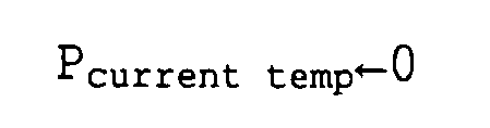
Thereafter, the temporary current position is updated with every computation cycle (e.g., every 100 msec). - Here, the
ETS circuit unit 22 includes an updown counter for counting encoder pulses of thespeed governor encoder 18. Assuming that a travel distance in one computation cycle of the updown counter is GCl, the temporary current position Pcurrent temp at the Nth computation cycle is calculated by the following formula.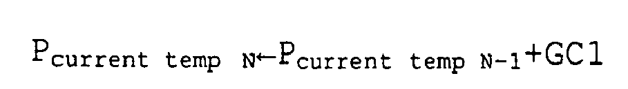
In other words, the temporary current position and the travel distance in one computation cycle are calculated as the number of encoder pulses. - In this manner, the temporary current position is updated according to the ascent of the
car 3. Positions at which the operation plates enter thereference sensors 23 to 26 and positions at which the operation plates exit from thereference sensors 23 to 26 are written in a table of a storage unit (memory) provided in theETS circuit unit 22. - When an enter of an operation plate to the
fourth reference sensor 26 is detected with, for example, the Nth computation cycle, the entering position Ptmp ETSD is calculated by the following formula.
The term "GC2" represents a travel distance of an updown counter after the enter to thefourth reference sensor 26.
The entering positions toother reference sensors - When the exit from the
reference sensor 26 is detected at the Nth computation cycle, the exit position Ptmp ETSU is calculated by the following formula.
The term "GC3" represents the travel distance of the updown counter after the exit from thefourth reference sensor 26.
The exit positions fromother reference sensors - When the writing of all entering positions and exit positions is finished, the
car 3 is stopped at a top floor position PTOP.
Here, theoperation control unit 12 is associated with the data of the bottom floor position PBOT and the top floor position PTOP based on an ideal zero point. Then, when thecar 3 is stopped at the top floor position PTOP, the data of the bottom floor position PBOT and the top floor position PTOP based on the ideal zero point is transmitted from theoperation control unit 12 to theelectronic safety controller 21. Theelectronic safety controller 21 converts, based on the information transmitted from theoperation control unit 12, the position data calculated as the temporary current position and written in the table to data based on the ideal zero point. As a result, detection of the current position Pcurrent based on the ideal zero point is possible. - A correction amount δ to the current position is calculated by the following formula.

Thus, adding the correction amount δ to the position data written in the table provides position data based on the ideal zero point. The corrected position data is written in E2PROM of theelectronic safety controller 21 and is subsequently used. - When the
car 3 is stopped at the top floor, the following processing is performed to change a position control from the position based on the temporary current position to the one based on the current position.

- When this correction is completed and the position control is switched to the position control based on the current position, the
electronic safety controller 21 outputs, to theoperation control unit 12, an instruction for permitting a high-speed operation to permit the execution of a high-speed automatic operation (i.e., normal operation mode). TheETS circuit unit 22 performs a normal monitoring operation. The normal monitoring operation uses the following formulae for calculating, with each computation cycle, a distance L1 between the upper face of thecar buffer 27 and the car and a distance L2 between the upper face of thecounterweight buffer 28 and thecounterweight 4.

- In the formulae, LKRB represents the distance between the upper face of the
buffer 27 and the bottom floor positions PBOT, and LCRB represents the distance between the top floor position PTOP and the position of thecar 3 at which thecounterweight 4 collides with the counterweight buffer 28 (CWT collision position of Fig.18). - In this elevator apparatus, the
car 3 is caused to travel at a speed equal to or lower than the allowable collision speed of thecar buffer 27 until the initialization operation is completed. This can more securely prevent thecar 3 from colliding with thecar buffer 27 at a speed exceeding the allowable collision speed, thus improving the reliability. - Although, in the example, the initialization operation is performed in two steps of the initialization of speed detection and the initialization of position detection, the initialization operation may be performed in three or more steps and an allowable car traveling speed may be determined for each step.
Further, the initialization operation is not limited to the initialization of speed detection and the initialization of position detection. - In this manner, the elevator apparatus in this example includes the elevator control apparatus that includes an operation control unit for controlling the operation of the car and a monitoring unit (electronic safety controller 21) for detecting an abnormal traveling of the car. When the monitoring unit is initialized, the operation control unit causes, according to a stage of the initialization, the car to travel at a speed lower than that in a normal operation.
- The monitoring unit outputs a permission signal regarding a car speed to the operation control unit according to a stage of the initialization.
Furthermore, the operation control unit controls the operation of the car by selectively switching plural operation modes including a normal operation mode and an initialization operation mode for initializing the monitoring unit while causing the car to travel. In the initialization operation mode, the operation control unit causes, according to a stage of the initialization, the car to travel at a speed lower than that in a normal operation mode. - The method of controlling the elevator apparatus in this example includes an initialization operation step to initialize the monitoring unit for detecting an abnormal traveling of the car while causing the car to travel. The initialization operation step causes, according to a stage of the initialization, the car to travel at a speed lower than that in a normal operation.
- Next, Fig. 19 is a circuit diagram of an abnormal contact point detection unit of the
electronic safety controller 21 of Fig. 1. Thesafety circuit unit 13 includes: a brake powersource contactor coil 111 for supplying power to thebrake unit 9; a motor powersource contactor coil 112 for supplying power to the motor unit of the drivingapparatus 7; a safety relaymain contact point 113 for turning ON and OFF the application of a voltage to the contactor coils 111 and 112; and a bypass relaymain contact point 114 connected in parallel to the safety relaymain contact point 113. - The brake power
source contactor coil 111, the motor powersource contactor coil 112, and the safety relaymain contact point 113 are connected to the power source so as to be arranged in series. The safetyrelaymain contact point 113 is closed in a normal operation. When the elevator has abnormality (e.g., when the traveling speed of thecar 3 exceeds a predetermined speed), the safety relaymain contact point 113 is opened. The bypass relaymain contact point 114 is opened during a normal operation. - The
electronic safety controller 21 includes: acontroller body 115; asafety relay coil 116 for operating the safety relaymain contact point 113; abypass relay coil 117 for operating the bypass relaymain contact point 114; a safety relaymonitor contact point 118 opened or closed while being mechanically connected to the safety relaymain contact point 113; and a bypass relaymonitor contact point 119 opened or closed while being mechanically connected to the bypass relaymain contact point 114. - The
safety relay coil 116, thebypass relay coil 117, the safety relaymonitor contact point 118, and the bypass relaymonitor contact point 119 are connected to thecontroller body 115 so as to be arranged in parallel. - The safety relay
main contact point 113 is mechanically coupled to the safety relaymonitor contact point 118 by a link mechanism (not shown) . Thus, when any one of the contact points 113 and 118 cannot operate due to adhesion or the like, the other of them cannot operate either. - The bypass relay
main contact point 114 is mechanically connected to the bypass relaymonitor contact point 119 by a link mechanism (not shown). Thus, when any one of the contact points 114 and 119 cannot operate due to adhesion or the like, the other of them cannot operate either. - The
controller body 115 includes: aprocessing unit 120; astorage unit 121; an input/output unit 122; a safety relay monitor contactpoint receiver circuit 123; a bypass relay monitor contactpoint receiver circuit 124; a safetyrelay driver circuit 125; and a bypassrelay driver circuit 126.
Theprocessing unit 120 is, for example, a CPU. Thestorage unit 121 is, for example, a RAM, a ROM, and a hard disk apparatus. Thestorage unit 121 stores, for example, data for judging abnormality of the elevator or a program for performing an operation test of the safety relaymain contact point 113. - The
processing unit 120 performs transmission and reception of signals with theoperation control unit 12 and various sensors via the input/output unit 122. - The safety relay monitor contact
point receiver circuit 123 is serially connected to the safety relaymonitor contact point 118 and detects the open/close state of the safety relaymonitor contact point 118. The bypass relay monitor contactpoint receiver circuit 124 is serially connected to the bypass relaymonitor contact point 119 and detects the open/close state of the bypass relaymonitor contact point 119. - The safety
relay driver circuit 125 is serially connected to thesafety relay coil 116 and switches between the excitation and non-excitation of thesafety relay coil 116. The bypassrelay driver circuit 126 is serially connected to thebypass relay coil 117 and switches between the excitation and non-excitation of thebypass relay coil 117. - The switching of the excitation or non-excitation of the
safety relay coil 116 is performed by outputting a safety relay instruction signal from theprocessing unit 120 to the safetyrelay driver circuit 125. The switching between the excitation or non-excitation of thebypass relay coil 117 is performed by outputting a bypass instruction signal from theprocessing unit 120 to the bypassrelay driver circuit 126. - The
receiver circuits driver circuits processing unit 120 so as to be arranged in parallel to each other. - Next, the operation will be explained. During the operation of the elevator, the
controller body 115 monitors the presence or absence of abnormality of the elevator based on the information from various sensors. When theprocessing unit 120 detects abnormality of the elevator, the safetyrelay driver circuit 125 stops the drive of thesafety relay coil 116. - As a result, the safety relay
main contact point 113 is opened and the conduction to the contactor coils 111 and 112 is blocked. As a result, the rotation of thedrive sheave 8 is braked by thebrake unit 9 and the conduction to the motor unit is blocked to thereby suddenly stop thecar 3. - Next, a method of testing an operation of the safety relay
main contact point 113 will be explained. Fig. 20 is a flowchart for explaining the method of testing an operation of the safety relaymain contact point 113 of Fig. 19. In this embodiment, the operation test is performed whenever thecar 3 is stopped at a stop floor in a normal operation. Thus, at the time of normal operation, theprocessing unit 120 monitors whether the traveling speed of thecar 3 becomes 0 according to the information from various sensors (stop detection step S61). - When the speed of the
car 3 is 0 and a safe state is provided, the bypassrelay driver circuit 126 excites thebypass relay coil 117. Thereafter, theprocessing unit 120 is on standby for a predetermined time (100 ms in this example) (step S62). Then, it is checked by the bypass relay monitor contactpoint receiver circuit 124 whether the bypass relaymonitor contact point 119 is closed (step S63). - When the bypass relay
monitor contact point 119 is not closed, this means that the bypass relaymain contact point 114 is also not closed. Thus, theprocessing unit 120 determines a failure of the bypass relay and thecontroller body 115 outputs abnormality detection signal to the operation control unit 12 (step S64). - When it is confirmed that the bypass relay
monitor contact point 119 is correctly closed, the safetyrelay driver circuit 125 excites thesafety relay coil 116. Thereafter, by the bypass relay monitor contactpoint receiver circuit 124 is on standby for a predetermined time (100 ms in this example) (test instruction step S65). Then, whether the safety relaymonitor contact point 118 is opened is checked by the safety relay monitor contact point receiver circuit 123 (abnormality detection step S66). - When the safety relay
monitor contact point 118 is not opened, this means that the safety relaymain contact point 113 is also not opened due to adhesion or the like. Thus, theprocessing unit 120 determines a failure of the safety relay and thecontroller body 115 outputs abnormality detection signal to the operation control unit 12 (step S64). - When it is judged that the safety relay
monitor contact point 118 is correctly opened, thesafety relay coil 116 is now brought into a non-excitation state. Thereafter, by the bypass relaymonitor contactpoint receiver circuit 124 is on standby for a predetermined time (100 ms in this example) (step S67). Then, it is checked by the safety relay monitor contactpoint receiver circuit 123 whether the safety relaymonitor contact point 118 is closed (step S68). - When the safety relay
monitor contact point 118 is not closed, theprocessing unit 120 judged that a failure of the safety relay has occurred, and thecontroller body 115 outputs an abnormality detection signal to the operation control unit 12 (step S64). - When it is checked that the safety relay
monitor contact point 118 is correctly closed, thebypass relay coil 117 is brought into a non-excitation state. Thereafter, theprocessing unit 120 is on standby for a predetermined time (100 ms in this example) (step S69) . Then, it is checked by the bypass relay monitor contactpoint receiver circuit 124 whether the bypass relaymonitor contact point 119 is opened (step S70). - When the bypass relay
monitor contact point 119 is not opened, theprocessing unit 120 determines a failure of the bypass relay and thecontroller body 115 outputs abnormality detection signal to the operation control unit 12 (step S64). - When the test of open and close operations of the safety relay
main contact point 113 and the bypass relaymain contact point 114 are completed, theprocessing unit 120 is on standby until the traveling speed of thecar 3 increases to be equal to or higher than a predetermined set value (step S71). Next, theETS circuit unit 22 monitors the traveling speed until thecar 3 stops. Then, whenever thecar 3 stops, the operation test is carried out to check the soundness of thesafety circuit unit 13. - In the elevator safety apparatus, timing at which the car stops in a normal operation is used to perform an operation test of the safety
relaymain contact point 113 . Thus, abnormality of the safetyrelaymain contact point 113 can be detected without causing hindrance in the normal operation and the reliability can be improved. - The operation test is carried out whenever the car stops, thereby making it possible to check the operation of the relay
main contact point 113 with a sufficient frequency and further improve the reliability. - Furthermore, the bypass relay
main contact point 114 is closed when the operation test of the safety relaymain contact point 113 is performed, it is possible to prevent the conduction to thesafety circuit unit 13 from being blocked during the operation test. Thus, it is possible to carry out the operation test while maintaining thesafety circuit unit 13. - Furthermore, it is also checked whether the safety relay
main contact point 113 and the bypass relaymain contact point 114 are correctly returned. Thus, the reliability can be further improved. - In the above example, the
brake unit 9 provides a braking operation when the safety relaymain contact point 113 is opened. However, the brake unit may provide a braking operation when the safety relay main contact point is closed. In this case, the operation test of a safety relay main contact point can also be carried out. - In the above example, the safety relay main contact point for operating the
brake unit 9 provided at thedriving apparatus 7 is described. However, the safety relay main contact point can also be applied to operate, for example, a rope brake to brake the car by gripping the main rope and a safety relay main contact point to operate a safety device provided at a counterweight. - Furthermore, in the example, the operation test is performed every time the
car 3 stops. However, timing at which the operation test is performed is not limited to this. For example, a counter for counting the number of stops of the car may be provided in the detection circuit body such that the operation test is performed at every number of stops set in advance. Alternatively, the detection circuit body may include a timer such that the operation test is performed at the first stop of the car after the elapse of a predetermined time. Further, the operation test may be performed only when the normal operation of the elevator is started (at the starting). Furthermore, the operation test may be performed only when the car stops at a predetermined floor. - In this manner, the
electronic safety controller 21 in this example generates, when the car stops during the normal operation, a safety relay instruction signal to operate the safety relay main contact point in a direction along which the brake unit provides a braking operation. Theelectronic safety controller 21 also detects whether the safety relay main contact point has operated according to the safety relay instruction signal. - The
electronic safety controller 21 also includes the safety relay monitor contact point that is opened and closed while being mechanically linked with the safety relay main contact point. Based on the state of the safety relay monitor contact point, theelectronic safety controller 21 detects the state of the safety relay main contact point.
Furthermore, the safety relay main contact point is closed during the normal operation, and is opened when the elevator has abnormality. The bypass relay main contact point connected in parallel with the safety relay main contact point and opened during the normal operation is provided in the safety circuit. Theelectronic safety controller 21 generates, prior to the generation of a safety relay instruction signal, a bypass instruction signal to close the bypass relay main contact point. - Furthermore, the
electronic safety controller 21 includes the bypass relay monitor contact point that is opened and closed while being mechanically linked with the bypass relay main contact point. Based on the state of the bypass relay monitor contact point, theelectronic safety controller 21 detects the state of the bypass relay main contact point. Theelectronic safety controller 21 also detects whether the bypass relay main contact point has operated according to the bypass instruction signal.
Furthermore, when abnormality of the safety relay main contact point is detected, theelectronic safety controller 21 outputs abnormality detection signal to the operation control unit. - Fig. 21 is a block diagram of the
electronic safety controller 21 of Fig. 1 connected to a history information recording unit and a soundness diagnosis unit. Theelectronic safety controller 21 is connected to a historyinformation recording unit 131 for recording the history of information regarding a judgment processing in the electronic safety controller 21 (processing process). The historyinformation recording unit 131 is a nonvolatile memory that continues to retain the information even when the power source of the elevator control apparatus is cut off. The memory includes, for example, a flush memory or a hard disk device. - Furthermore, the
electronic safety controller 21 and the historyinformation recording unit 131 are connected to asoundness diagnosis unit 132 for automatically diagnosing the soundness of theelectronic safety controller 21. Thesoundness diagnosis unit 132 can also diagnose the soundness of the entirety of a system such as various sensors or thesafety circuit unit 13. The result of the diagnosis by thesoundness diagnosis unit 132 is recorded in the historyinformation recording unit 131. - Fig. 22 is an explanatory diagram of an example of information stored in the history
information recording unit 131 of Fig. 21. History information includes time, a car position, a car speed, a set value (threshold value) calculated according to a car position, a judgment result, and analysis data such as an internal variable. - The history
information recording unit 131 accumulates combinations of data such as data of car positions, data of car speeds, data of set values, data of judgment results, and analysis data that are divided for each corresponding time. A data table as shown in Fig. 22 is prepared. - Fig. 23 is a flowchart for explaining an operation of the
electronic safety controller 21 of Fig. 21. First, data of the current time is outputted to the history information recording unit 131 (step S81). Next, the position of the car is detected (step S82). The detected car position data is outputted to the history information recording unit 131 (step S83). Thereafter, the speed of thecar 3 is detected (step S84). The detected car position data is outputted to the history information recording unit 131 (step S85) . - Next, a set value corresponding to the car position is calculated (step S86). The data of the set value is outputted to the history information recording unit 131 (step S87) . Thereafter, a detected speed "v" is compared with a set value "f (x)" (stepS88). When the detected speed "v" is lower than the set value "f(x)", the judgment result is "no abnormality" (Good) and is outputted to the history information recording unit 131 (step S89). When the car speed has no abnormality, this operation is repeated with every computation cycle.
- When the result of the comparison judgment shows the detected speed "v" equal to or higher than the set value "f(x)", a stop instruction signal is outputted to the safety circuit unit 13 (step S90) . In this case, the judgment result is "abnormality found (Bad) and is outputted to the history information recording unit 131 (step S91).
- The history
information recording unit 131 sequentially stores the data sent from theelectronic safety controller 21. - According to this elevator apparatus, when the
car 3 is suddenly stopped according to an instruction from theelectronic safety controller 21, it is possible to check the soundness of theelectronic safety controller 21 by checking the history recorded in the historyinformation recording unit 13. When thecar 3 is suddenly stopped in spite of a judgment result of "no abnormality", it can be judged that theelevator control panel 11 has a failure. - Therefore, a cause of the sudden stop of the
car 3 can be judged efficiently. This can provide an efficient recovery operation.
Furthermore, instead of a procedure in a periodic inspection operation for actually inputting inspection signals for any possible states to judge whether the computation results of set values and judgment results are correct, the history information can be checked to obtain a part of an inspection result, thereby making it possible to simplify the inspection operation. Simply by checking the calculation result of set values and the comparison and judgment results stored in the historyinformation recording unit 131, it is possible to complete a part of the periodic inspection, thereby reducing the number of inspection items. - Furthermore, the set value set by the
electronic safety controller 21 is set with a margin taking into account vibration of the car due to mischief. The range of the margin can also be adjusted for each elevator. By analyzing the data of the judgment result recorded in the historyinformation recording unit 131, a level of the margin required for an actual operation circumstance can be checked and the margin can be minimized. This makes it possible to provide a higher car speed and improve the service efficiency. This can also simplify an operation for adjusting the margin. In other words, history information during a normal operation can be analyzed to reduce items in an adjustment operation. - Next, specific examples of contents to be diagnosed by the
soundness diagnosis unit 132 are described below. - 1. Diagnosis of failure of sensor
- · Check of the behavior of a position to time (continuousness, amount of change, presence or absence of noise or the like)
- · Check of the behavior of a speed to time (continuousness, amount of change, presence or absence of noise or the like)
- · Check of failure of a sensor
- 2. Diagnosis of operation of speed monitoring unit
- · Timing of the operation (operation interval) (from times t1 and t2)
- · Check of the result of the computation of a set value to a car position
- · Check of the result of the judgment according to a comparison between a detection speed and a set value
- · Diagnosis of a failure of an electronic element (e.g., CPU, ROM, RAM)
- 3. Diagnosis of output value of speed monitoring unit
- · Check of the behavior of an output value (presence or absence of noise or the like)
- · Check of the output to a safety circuit corresponding to a judgment result
- 4. Check of operation of self-diagnosis function of safety device · Check of the self-diagnosis operation (timing, diagnosis item) · Check of the history of detected abnormalities
- 5. Diagnosis of presence or absence of operation for suddenly stopping car and state during operation
- · Check of the detection of a failure of a safety device by a self-diagnosis (position of failure detection, check of cause of failure)
- · Check of an incorrect output (check of consistency between an output and a logic computation)
- · Check of a position and speed immediately before the operation (check of the behavior leading to an abnormal speed, presence or absence of mischief or the like)
- By adding the processing to compile information for the history of the diagnosis results to thereby record the result of the compiling processing in the history
information recording unit 131, it is also possible to alleviate an operation to check the history information. Specific examples of the result of the compiling processing to be recorded are described below. - · Right and wrong of the timing of an operation
- · Right and wrong of the soundness of an input function based on the history of sensor inputs
- · Right and wrong of the soundness of a logic computation
- · Right and wrong of an output function
- · Right and wrong of a self-diagnosis operation and its result
- · Presence or absence of abnormality of the apparatus
- In this elevator apparatus, the result of the diagnosis of the soundness of a system can be checked by the history
information recording unit 131. Thus, when thecar 3 is suddenly stopped because of a failure of an electronic element, the electronic element that has caused the failure can be identified efficiently. - Furthermore, the diagnosis results recorded in the history
information recording unit 131 and the compiled results thereof can be checked to thereby reduce the number of inspection items of a periodic inspection. Items to be checked in a periodic inspection are as follows. - · Check of areas for which the soundness of the operation is already checked based on a car position and a car speed (areas for which an inspection regarding "x" and "v" is already performed)
- · Check of inspection items that are already checked by self-diagnosis
- · Check of a margin between a detection speed and a set value
- In this manner, when, for example, an electronic element (e.g., CPU, ROM, RAM) is diagnosed with regards to the soundness, the diagnosis result recorded in the history
information recording unit 131 can be checked. Thus, an inspection of the electronic element in a periodic inspection can be omitted. - In addition to the recording of history information and the recording of the result of the diagnosis of soundness, items that are checked in a periodic inspection may be recorded in the history
information recording unit 131. In this case, the inspection history can be retained in the historyinformation recording unit 131 such that the contents carried out in the periodic inspection can be checked easily. Inspection histories to be recorded include, for example, time at which the inspection is carried out and inspection items. - In this example, the history
information recording unit 131 and thesoundness diagnosis unit 132 are provided outside theelectronic safety controller 21. However, at least one of the historyinformation recording unit 131 and thesoundness diagnosis unit 132 may be provided in theelectronic safety controller 21. - Furthermore, in this example, information of the history of the monitoring of an abnormal speed is recorded. However, information on the history of rope-cut monitoring for monitoring damages to or cut of a main rope may be recorded. Alternatively, information of the history of the temperature of a motor of a traction machine, the temperature of an inverter, or the temperature of a control panel may be recorded.
- In this manner, the elevator apparatus in this example includes: the abnormality monitoring unit (electronic safety controller 21) that judges, based on information from a sensor, presence or absence of abnormality of the elevator to output a signal for stopping the car when abnormality is detected; and the history information recording unit that records the history of information regarding the judgment processing in the abnormality monitoring unit.
- Next, Fig. 24 is a block diagram of the main part of the
electronic safety controller 21 of Fig. 1. Theelectronic safety controller 21 has: a memory dataabnormality check circuit 141 for checking abnormality of memory data; aCPU 142; and a designatedaddress detection circuit 143 for checking abnormality of an address bus. - The memory data
abnormality check circuit 141 has: amain memory 141a and asub memory 141b (RAM) having a parallel configuration in which themain memory 141a and thesub memory 141b are allocated to the same address space in a superimposed manner; adata buffer 141c for preventing the collision with output data of thesub memory 141b; and adata comparison circuit 141d for comparing the respective pieces of data of themain memory 141a and thesub memory 141b to thereby check abnormality of the data. - Although not shown, the memory data
abnormality check circuit 141 also has an error-correcting code check circuit as in the case of a conventional system. - The
CPU 142 has: designatedaddress output software 142a for outputting a designated address during a data abnormality check; data busabnormality check software 142b executed during a data bus abnormality check; and a ROM for storing a program (not shown). - In the memory data
abnormality check circuit 141, themain memory 141a and thesub memory 141b are connected to theCPU 142 via an address bus BA and a data bus BD, respectively. Data of theelectronic safety controller 21 is written in themain memory 141a and thesub memory 141b from theCPU 142, and the data are read from themain memory 141a and thesub memory 141b by theCPU 142. - In the memory data
abnormality check circuit 141, the data bus BD branches into a main memory data bus BD1 and a sub memory data bus BD2. Themain memory 141a and thesub memory 141b are connected to thedata comparison circuit 141d via the main memory data bus BD1 and the sub memory data bus BD2, respectively. Thedata buffer 141c is interposed at the sub memory data bus BD2. - When abnormality of memory data is checked, the
data comparison circuit 141d compares the respective pieces of memory data inputted via the main memory data bus BD1 and the sub memory data bus BD2, respectively. When it is judged that the memory data has abnormality, thedata comparison circuit 141d outputs a data abnormality signal ED. - The designated
address detection circuit 143 is connected to theCPU 142 via the address bus BA. When abnormality of the address bus BA is checked, the designatedaddress detection circuit 143 detects a designated address and, when it is judged that the address bus BA has abnormality, outputs an address bus abnormality signal EBA. - The designated
address output software 142a in theCPU 142 operates when abnormality of the address bus BA is checked, and outputs, as described later, a designated address to the designatedaddress detection circuit 143 in a cyclic manner. The data busabnormality check software 142b in theCPU 142 operates when abnormality in the data bus BD is checked and, when it is judged that the data bus BD has abnormality, outputs a data bus abnormality signal EBD. - Fig. 25 specifically shows the
data comparison circuit 141d for the data abnormality check of Fig. 24. Fig. 25 shows a case in which thedata comparison circuit 141d includes plural exclusive ORgates 151, an ANDgate 152, and a D-type latch circuit 153 that uses a memory read signal RD. - In Fig. 25, the data comparison circuit 141dhas: the exclusive OR
gates 151 provided in parallel; the ANDgate 152 to calculate a logical product of the respective output signals of the exclusive ORgates 51; and the D-type latch circuit 153 to use the output signal of the ANDgate 152 as a D terminal input to output a H (logic "1") level signal as the data abnormality signal ED. - Each of the exclusive OR
gates 151 receives data from the main memory data bus BD1 as an input signal from one side, and also receives the data from the sub memory data bus BD2 as an input signal from the other side. When those input signals are identical, the respective exclusive ORgates 151 output L (logic "0") level signals and, when those input signals are not identical, output H (logic "1") level signals. - The AND
gate 152 accepts inversion signals of output signals from the respective exclusive ORgates 151 to output, when the respective input signals are all at H level (i.e., output signals of the exclusive ORgates 151 are all at L level), the H (logic "1") level signal. - The D-
type latch circuit 153 operates in response to the memory read signal RD and changes the level of the output signal (data abnormality signal ED) in response to the D terminal input (output signal of AND gate 152) and is reset to the initial state in response to a reset signal RST. - Fig. 26 is a specific illustration of the designated
address detection circuit 143 for the address bus abnormality check of Fig. 24. - In Fig. 26, the designated address detection circuit 143 has: plural exclusive OR gates 161 that receive the H level signal as one input signal; plural exclusive OR gates 162 that receive the L level signal as the other input signal; a NAND gate 163 that calculates a logical product of the respective output signals of the exclusive OR gates 161 and an address strobe signal STR; a NAND gate 164 that calculates a logical product of the respective output signals of the exclusive OR gate 162 and an address strobe signal STR; a D-type latch circuit 165 for providing the output signal of the NAND gate 163 as an input signal of a set terminal; a D-type latch circuit 166 for providing the output signal of the NAND gate 164 as an input signal of a set terminal; anANDgate 167 that calculates a logical product of the respective output signals of the D-type latch circuits 165 and 166; a D-type latch circuit 168 that operates in response to a reset signal RST1 of the designated address detection circuit 143; a D-type latch circuit 169 that operates in response to a mask signal MSK of the designated address detection circuit 143; and an OR gate 170 that calculates a logic product of the output signal of the AND gate 167 and the output signal of the D-type latch circuit 169.
- The other input terminals of the exclusive OR
gates - When a designated address of the H level signal is inputted from the address bus BA, each of the exclusive OR
gates 161 outputs the L level signal. When a designated address of the L level signal is inputted, each of the exclusive ORgates 161 outputs the H level signal. - In contrast, when a designated address of the H level signal is inputted from the address bus BA, each of the exclusive OR
gates 162 outputs the H level signal. When a designated address of the H level signal is inputted, each of the exclusive ORgates 162 outputs the L level signal. - An output signal from each of the exclusive OR
gates 161 is level-inverted together with the address strobe signal STR and is inputted to theNAND gate 163. Similarly, an output signal from each of the exclusive ORgates 162 is level-inverted together with the address strobe signal STR and is inputted to theNAND gate 164. - Thus, when the address bus BA is sound, by designated addresses ("FFFF", "0000") periodically inputted via the address bus BA, the
NAND gates NAND gates - In the D-
type latch circuit 168, the D input terminal is applied with the L level signal, and the D-type latch circuit 168 is operated by the first reset signal RST1. An output signal of the D-type latch circuit 168 is applied to the respective reset terminals of the D-type latch circuits type latch circuit 169, the D input terminal is applied with a 0 bit signal BTO of the data bus BD ("0" at mask ON and "1" at mask OFF) and the D-type latch circuit 169 is operated by the mask signal MSK. The respective D-type latch circuits - When the output signal of the AND
gate 167 or the output signal of the D-type latch circuit 169 show the H level, theOR gate 170 outputs an address bus abnormality signal EBA. - In the
electronic safety controller 21 having this configuration, not only the data abnormality check by the memory dataabnormality check circuit 141 but also the abnormality check of the address bus BA by the designatedaddress output software 142a and the designatedaddress detection circuit 143 and the abnormality check of the data bus BD by the data busabnormality check software 142b are performed. - Next, the three types of abnormality check operations will be explained in further detail with reference to Fig. 24 to Fig. 28.
Fig. 27 is a flowchart of the processing operation by the designatedaddress output software 142a and the designatedaddress detection circuit 143 in theCPU 142 of Fig. 24. Fig. 27 shows an operation procedure when a designated address is outputted to the designatedaddress detection circuit 143 to check abnormality of the address bus BA.
Fig. 28 is a flowchart of the processing operation by the data busabnormality check software 142b in theCPU 142 of Fig. 24. - First, an operation for checking abnormal data by the memory data
abnormality check circuit 141 will be explained with reference to Fig. 24 and Fig. 25.
In the memory dataabnormality check circuit 141, themain memory 141a and thesub memory 141b are allocated with the same address space in a superimposed manner. When theCPU 142 writes data to themain memory 141a and thesub memory 141b, the same data is written in the same address of themain memory 141a and thesub memory 141b, respectively. - On the other hand, when the
CPU 142 reads data from themain memory 141a and thesub memory 141b, the data of themain memory 141a is read onto the main memory data bus BD1 and is sent to theCPU 142 via the data bus BD. However, the data of thesub memory 141b is read onto the sub memory data bus BD2 but is blocked by thedata buffer 141c and thus is not sent to the data bus BD. - Thus, only the data of the
main memory 141a is sent to theCPU 142 without causing the collision of two memory outputs from themain memory 141a and thesub memory 141b, and writing and reading are performed correctly. - Simultaneously with this operation, the main memory data read onto the main memory data bus BD1 and the sub memory data read onto the sub memory data bus BD2 are inputted to the
data comparison circuit 141d and the comparison between the former and the latter is performed. - The
data comparison circuit 141d checks abnormality of the data and, when abnormality (data inconsistency) is detected, outputs the data abnormality signal ED. - Next, an operation for checking abnormality of the address bus BA by the designated
address output software 142a and the designatedaddress detection circuit 143 in theCPU 142 will be explained with reference to Fig. 24, Fig. 26, and Fig. 27. - With regards to all of the respective bit signals used for a memory system in the address bus BA, the
CPU 142 executes the designatedaddress output software 142a using designated addresses for check with which both cases of "0" and "1" can be checked (e.g., "FF" and "00" in the case of 8 bits) to repeatedly perform the processing of Fig. 27 (steps S101 to S104) in a cyclic manner. At the same time, the designatedaddress detection circuit 143 provided on the address bus BA is caused to detect the designated address. When the designatedaddress detection circuit 143 cannot detect all of the designated addresses, the designatedaddress detection circuit 143 judges that the address bus BA has abnormality to output the address bus abnormality signal EBA. - In Fig. 27, first, the
CPU 142 turns ON the mask of the designated address detection circuit 143 (step S101) to operate the D-type latch circuit 169 in the designatedaddress detection circuit 143 and applies the 0 bit signal BTO (=0) to the D input terminal. Next, the first reset signal RST1 is used to reset the designated address detection circuit 143 (stepS102) to operate the D-type latch circuit 168. - Next, the maximum address "FFFF" at which all addresses are "1" (or the minimum address at which all addresses are "0") is read (step S103) . Finally, the mask of the designated
address detection circuit 143 is turned OFF (step S104). A 0 bit signal BTO(=1) is applied to the D input terminal of the D-type latch circuit 169 to invert the operation state of the D-type latch circuit 169 to thereby complete the processing routine of Fig. 27. - Next, an operation for checking abnormality of the data bus BD by the data bus
abnormality check software 142b in theCPU 42 will be explained with reference to Fig. 24 and Fig. 28.
With regards to all of the respective bit signals used for a memory system in the data bus BD, theCPU 142 repeatedly executes, in a cyclic manner, a read/write check operation by the processing (S105 to S111) of Fig. 28 using designated addresses for check with which both cases of "0" and "1" can be checked (e.g., "AA" and "55" or pairs of values of "01", "02", "04", "08", "10", "20", "40", and "80" in the case of 8 bits). - When all pieces of specified data are inconsistent in the judgment processing by the data bus
abnormality check software 142b, theCPU 142 judges that the data bus BD has abnormality to output the data bus abnormality signal EBD. - In Fig. 28, first, the
CPU 142 initializes a variable N to identify specified data to be "1" (step S105) and writes Nth (N=1) specified data (=01) to a test address of the RAM (main memory 141a andsub memory 141b) (step S106). Next, theCPU 142 reads the specified data written in step S12 from the test address (step S107) to judge whether the data is consistent with specified data before being written (step S108). - When, it is judged in step S108 that the specified data after being read is inconsistent with the specified data before being written (i.e., NO), the
CPU 142 assumes that the data bus BD has abnormality to output the data bus abnormality signal EBD (step S109) to cause an abnormal end. - When step S108 judges that the specified after being read is consistent with the specified data before being written (i. e. , YES), then the variable N is incremented (step S110) and it is judged whether the variable N is "8" or less (step S111).
- When step S111 determines N≤8 (i.e., YES), the processing returns to the processing to write specified data (step S106) to repeatedly perform steps S107 to S110. In other words, the second specified data (="02"), the third specified data (="02"), ··· and the eighth specified data (="80") are sequentially written in the test address in the RAM (step S106). After the respective pieces of data are read (step S107), consistency or inconsistency is judged (step S108).
- On the other hand, when step S111 determines N>9 (i.e., NO), all pieces of specified data (N=1 to 8) are checked with regards to abnormality of the data bus and it is assumed that all pieces of specified data are consistent before and after being written. In this case, the
CPU 142 successfully completes the processing routine of Fig. 28. - In this manner, by performing not only the processing by the memory data
abnormality check circuit 141 as in a conventional system but also the cyclic abnormality check processing of the address bus BA and the data bus BD used when the memory is written and read, thereby making it possible to provide an improved reliability in the abnormality check. - The abnormality check is particularly effective to check the soundness of a memory system in the elevator electronic safety apparatus.
- In this manner, the
electronic safety controller 21 in this example includes: the CPU having the designated address output software and the data bus abnormality check software; the main memory and the sub memory connected to the CPU via the address bus and the data bus; the memory data abnormality check circuit that compares the data of the main memory with that of the sub memory; and the designated address detection circuit connected to the CPU via the addressbus. The CPU executes the designated address output software and uses the designated address detection circuit to check abnormality of the address bus in a cyclic manner. The CPU executes the data bus abnormality check software and uses the main memory and the sub memory to check abnormality of the data bus in a cyclic manner. - Furthermore, the CPU executes the designated address output software to output, with regards to all of the respective bit signals used for the main memory and the sub memory in an address bus designated addresses for check with which both cases of "0" and "1" can be checked to the designated address detection circuit. Then, the designated address detection circuit detects plural designated addresses outputted from the CPU in a cyclic manner and, when the CPU cannot detect all of the designated addresses, the CPU judges that abnormality of the address bus has occurred and outputs an address bus abnormality signal.
- Furthermore, the CPU executes the data bus abnormality check software to input and output, with regards to all of the bit signals used for the main memory and the sub memory in the data bus, designated addresses for check with which both cases of "0" and "1" can be checked to once write plural pieces of specified data cyclically outputted from the CPU in the main memory and the sub memory and subsequently read and compare the pieces of specified data. When all of the specified data before being written and the specified data after being written are inconsistent, the CPU determines that abnormality of the data bus has occurred and outputs a data bus abnormality signal.
Claims (5)
- An elevator apparatus, comprising:a sensor that generates detection signal for detecting a state of an elevator; andan electronic safety controller that detects abnormality of the elevator based on the detection signal from the sensor to output an instruction signal for shifting the elevator to a safe state,wherein the electronic safety controller can detect abnormality of the electronic safety controller itself and, when abnormality of the electronic safety controller itself is detected, the electronic safety controller also outputs the instruction signal for shifting the elevator to the safe state.
- The elevator apparatus according to claim 1, wherein the electronic safety controller can detect abnormality of the sensor and, when abnormality of the sensor is detected, the electronic safety controller also outputs the instruction signal for shifting the elevator to the safe state.
- The elevator apparatus according to claim 1, wherein:the electronic safety controller includes a microprocessor that executes arithmetic processing for detecting abnormality of the elevator; andthe microprocessor periodically executes arithmetic processing for detecting abnormality of the electronic safety controller itself.
- The elevator apparatus according to claim 1, wherein:the electronic safety controller includes a microprocessor that executes arithmetic processing for detecting abnormality of the elevator; andthe microprocessor executes, when a predetermined state is satisfied, arithmetic processing for detecting abnormality of the electronic safety controller itself.
- The elevator apparatus according to claim 1, wherein:the electronic safety controller includes a first microprocessor that executes arithmetic processing for detecting abnormality of the elevator based on a first safety program and a second microprocessor that executes arithmetic processing for detecting abnormality of the elevator based on a second safety program; andthe first and secondmicroprocessors can communicate with each other via an interprocessor bus and can compare arithmetic processing results with each other to check the soundness of the first and second microprocessors.
Applications Claiming Priority (1)
| Application Number | Priority Date | Filing Date | Title |
|---|---|---|---|
| PCT/JP2004/013926 WO2006033153A1 (en) | 2004-09-24 | 2004-09-24 | Elevator apparatus |
Publications (3)
| Publication Number | Publication Date |
|---|---|
| EP1792864A1 true EP1792864A1 (en) | 2007-06-06 |
| EP1792864A4 EP1792864A4 (en) | 2012-04-04 |
| EP1792864B1 EP1792864B1 (en) | 2017-10-25 |
Family
ID=36089920
Family Applications (1)
| Application Number | Title | Priority Date | Filing Date |
|---|---|---|---|
| EP04788085.1A Active EP1792864B1 (en) | 2004-09-24 | 2004-09-24 | Elevator apparatus |
Country Status (4)
| Country | Link |
|---|---|
| EP (1) | EP1792864B1 (en) |
| JP (1) | JP5350590B2 (en) |
| CN (1) | CN101027238B (en) |
| WO (1) | WO2006033153A1 (en) |
Cited By (2)
| Publication number | Priority date | Publication date | Assignee | Title |
|---|---|---|---|---|
| WO2018033902A1 (en) * | 2016-08-18 | 2018-02-22 | Yoram Madar | Elevator brake monitoring and control |
| US11535487B2 (en) | 2018-11-23 | 2022-12-27 | Otis Elevator Company | Elevator safety system |
Families Citing this family (17)
| Publication number | Priority date | Publication date | Assignee | Title |
|---|---|---|---|---|
| CN102036898B (en) * | 2008-06-27 | 2013-05-01 | 三菱电机株式会社 | Elevator apparatus and operating method thereof |
| JP4784949B2 (en) * | 2009-03-09 | 2011-10-05 | 東芝エレベータ株式会社 | Elevator operation control device |
| JP5568962B2 (en) * | 2009-11-25 | 2014-08-13 | 三菱電機株式会社 | Elevator control device |
| JP5222833B2 (en) * | 2009-12-11 | 2013-06-26 | 株式会社日立製作所 | Electronic safety elevator |
| JP5492732B2 (en) * | 2010-10-21 | 2014-05-14 | 株式会社日立製作所 | Electronic safety elevator |
| JP5783993B2 (en) * | 2012-12-19 | 2015-09-24 | 株式会社日立製作所 | Electronic safety elevator |
| JP6190171B2 (en) * | 2013-06-10 | 2017-08-30 | 株式会社日立製作所 | elevator |
| CN103278325A (en) * | 2013-06-13 | 2013-09-04 | 金石机器人常州有限公司 | Vertical movement component falling monitoring system and method thereof |
| CN103395668B (en) * | 2013-08-20 | 2015-08-05 | 黄平刚 | A kind of emergency stop protection device for elevator |
| JP6220613B2 (en) * | 2013-09-19 | 2017-10-25 | 株式会社日立製作所 | Elevator control system |
| JP6120977B2 (en) * | 2013-09-20 | 2017-04-26 | 三菱電機株式会社 | Elevator equipment |
| CN104590965B (en) * | 2015-01-14 | 2017-04-12 | 深圳市正弦电气股份有限公司 | Method and device for detecting abnormal operation of elevator |
| JP5985686B1 (en) * | 2015-03-10 | 2016-09-06 | 東芝エレベータ株式会社 | elevator |
| CN109476450B (en) * | 2016-07-29 | 2020-07-07 | 三菱电机株式会社 | Control device for elevator |
| CN111094164B (en) * | 2017-09-13 | 2021-05-04 | 因温特奥股份公司 | Checking the state of field devices of a people conveyor system associated with a building |
| JP6975108B2 (en) * | 2018-08-20 | 2021-12-01 | 株式会社日立ビルシステム | Elevator diagnostic system and elevator diagnostic method |
| WO2022254938A1 (en) | 2021-06-03 | 2022-12-08 | 二朗 渡邊 | Circular saw guide device |
Citations (4)
| Publication number | Priority date | Publication date | Assignee | Title |
|---|---|---|---|---|
| US3961688A (en) * | 1974-04-29 | 1976-06-08 | Armor Elevator Company | Transportation system with malfunction monitor |
| WO2000051929A1 (en) * | 1999-03-04 | 2000-09-08 | Otis Elevator Company | Electronic safety system for elevators |
| US6392537B1 (en) * | 1998-02-27 | 2002-05-21 | Nabco Limited | Remote monitoring system for automatic door systems |
| WO2007011359A1 (en) * | 2005-07-18 | 2007-01-25 | Otis Elevator Company | Remotely performed and/or assisted restoration of elevator service |
Family Cites Families (3)
| Publication number | Priority date | Publication date | Assignee | Title |
|---|---|---|---|---|
| DE4032033A1 (en) | 1990-10-09 | 1992-04-16 | Siemens Ag | Electric control and monitoring for underground plant - triggering safety-relevant signals for transmission over independent paths and processing by redundant systems |
| JPH08305664A (en) * | 1995-04-28 | 1996-11-22 | Nec Home Electron Ltd | Method and device for cpu monitoring |
| JP4204299B2 (en) * | 2002-10-18 | 2009-01-07 | 東芝エレベータ株式会社 | Elevator control device |
-
2004
- 2004-09-24 JP JP2006536285A patent/JP5350590B2/en active Active
- 2004-09-24 EP EP04788085.1A patent/EP1792864B1/en active Active
- 2004-09-24 CN CN2004800440576A patent/CN101027238B/en active Active
- 2004-09-24 WO PCT/JP2004/013926 patent/WO2006033153A1/en active Application Filing
Patent Citations (4)
| Publication number | Priority date | Publication date | Assignee | Title |
|---|---|---|---|---|
| US3961688A (en) * | 1974-04-29 | 1976-06-08 | Armor Elevator Company | Transportation system with malfunction monitor |
| US6392537B1 (en) * | 1998-02-27 | 2002-05-21 | Nabco Limited | Remote monitoring system for automatic door systems |
| WO2000051929A1 (en) * | 1999-03-04 | 2000-09-08 | Otis Elevator Company | Electronic safety system for elevators |
| WO2007011359A1 (en) * | 2005-07-18 | 2007-01-25 | Otis Elevator Company | Remotely performed and/or assisted restoration of elevator service |
Non-Patent Citations (1)
| Title |
|---|
| See also references of WO2006033153A1 * |
Cited By (3)
| Publication number | Priority date | Publication date | Assignee | Title |
|---|---|---|---|---|
| WO2018033902A1 (en) * | 2016-08-18 | 2018-02-22 | Yoram Madar | Elevator brake monitoring and control |
| US10221040B2 (en) | 2016-08-18 | 2019-03-05 | Yoram Madar | Elevator brake monitoring and control |
| US11535487B2 (en) | 2018-11-23 | 2022-12-27 | Otis Elevator Company | Elevator safety system |
Also Published As
| Publication number | Publication date |
|---|---|
| JP5350590B2 (en) | 2013-11-27 |
| EP1792864A4 (en) | 2012-04-04 |
| EP1792864B1 (en) | 2017-10-25 |
| WO2006033153A1 (en) | 2006-03-30 |
| CN101027238B (en) | 2013-01-02 |
| CN101027238A (en) | 2007-08-29 |
| JPWO2006033153A1 (en) | 2008-05-15 |
Similar Documents
| Publication | Publication Date | Title |
|---|---|---|
| EP1852382B1 (en) | Elevator apparatus | |
| EP1792864B1 (en) | Elevator apparatus | |
| JP5380407B2 (en) | Safety elevator | |
| US4898263A (en) | Elevator self-diagnostic control system | |
| RU2509049C2 (en) | Method of carrier protection | |
| US6170614B1 (en) | Electronic overspeed governor for elevators | |
| US10006455B2 (en) | Drive control apparatus | |
| US6988594B2 (en) | Elevator door monitoring system | |
| EP2671836B1 (en) | Safety control device for elevator | |
| WO2000051929A1 (en) | Electronic safety system for elevators | |
| US20190300337A1 (en) | Elevator with safety chain overlay control unit with a safety plc separately monitoring various safety switches for increasing a safety integrity level | |
| WO2005105646A1 (en) | Control device of elevator | |
| US6439350B1 (en) | Differentiating elevator car door and landing door operating problems | |
| US20080082212A1 (en) | Programmable Controller | |
| US5139113A (en) | Apparatus for detecting abnormalities in elevator motion | |
| KR100894371B1 (en) | Elevator apparatus | |
| EP0590637B1 (en) | Detection of improper CPU operation from lap time pulses and count of executed significant steps | |
| CN113939774A (en) | Task scheduling management device | |
| KR20070012457A (en) | Elevator apparatus | |
| JPS6223712B2 (en) | ||
| JP7285070B2 (en) | Platform door condition diagnosis system, platform door condition diagnosis method, mobile device condition diagnosis method | |
| KR100186374B1 (en) | Elevator check system and the control method | |
| JPH11100183A (en) | Diagnosis operation device of elevator | |
| CN109071163B (en) | Elevator switching signal diagnosis device and elevator maintenance plan generation system | |
| JPH05108418A (en) | Detection system for program abnormality |
Legal Events
| Date | Code | Title | Description |
|---|---|---|---|
| PUAI | Public reference made under article 153(3) epc to a published international application that has entered the european phase |
Free format text: ORIGINAL CODE: 0009012 |
|
| 17P | Request for examination filed |
Effective date: 20061011 |
|
| AK | Designated contracting states |
Kind code of ref document: A1 Designated state(s): DE ES FR NL PT |
|
| DAX | Request for extension of the european patent (deleted) | ||
| RBV | Designated contracting states (corrected) |
Designated state(s): DE ES FR NL PT |
|
| A4 | Supplementary search report drawn up and despatched |
Effective date: 20120302 |
|
| RIC1 | Information provided on ipc code assigned before grant |
Ipc: B66B 5/06 20060101ALI20120227BHEP Ipc: B66B 5/02 20060101ALI20120227BHEP Ipc: B66B 1/28 20060101ALI20120227BHEP Ipc: B66B 3/00 20060101ALI20120227BHEP Ipc: B66B 5/00 20060101AFI20120227BHEP |
|
| 17Q | First examination report despatched |
Effective date: 20130225 |
|
| GRAP | Despatch of communication of intention to grant a patent |
Free format text: ORIGINAL CODE: EPIDOSNIGR1 |
|
| STAA | Information on the status of an ep patent application or granted ep patent |
Free format text: STATUS: GRANT OF PATENT IS INTENDED |
|
| INTG | Intention to grant announced |
Effective date: 20170508 |
|
| RIN1 | Information on inventor provided before grant (corrected) |
Inventor name: MATSUOKA, TATSUO |
|
| GRAS | Grant fee paid |
Free format text: ORIGINAL CODE: EPIDOSNIGR3 |
|
| GRAA | (expected) grant |
Free format text: ORIGINAL CODE: 0009210 |
|
| STAA | Information on the status of an ep patent application or granted ep patent |
Free format text: STATUS: THE PATENT HAS BEEN GRANTED |
|
| AK | Designated contracting states |
Kind code of ref document: B1 Designated state(s): DE ES FR NL PT |
|
| REG | Reference to a national code |
Ref country code: DE Ref legal event code: R096 Ref document number: 602004051958 Country of ref document: DE |
|
| REG | Reference to a national code |
Ref country code: NL Ref legal event code: FP |
|
| PG25 | Lapsed in a contracting state [announced via postgrant information from national office to epo] |
Ref country code: ES Free format text: LAPSE BECAUSE OF FAILURE TO SUBMIT A TRANSLATION OF THE DESCRIPTION OR TO PAY THE FEE WITHIN THE PRESCRIBED TIME-LIMIT Effective date: 20171025 |
|
| REG | Reference to a national code |
Ref country code: DE Ref legal event code: R026 Ref document number: 602004051958 Country of ref document: DE |
|
| PLBI | Opposition filed |
Free format text: ORIGINAL CODE: 0009260 |
|
| PLAX | Notice of opposition and request to file observation + time limit sent |
Free format text: ORIGINAL CODE: EPIDOSNOBS2 |
|
| REG | Reference to a national code |
Ref country code: FR Ref legal event code: PLFP Year of fee payment: 15 |
|
| 26 | Opposition filed |
Opponent name: KONE CORPORATION Effective date: 20180724 |
|
| PLBB | Reply of patent proprietor to notice(s) of opposition received |
Free format text: ORIGINAL CODE: EPIDOSNOBS3 |
|
| PG25 | Lapsed in a contracting state [announced via postgrant information from national office to epo] |
Ref country code: PT Free format text: LAPSE BECAUSE OF FAILURE TO SUBMIT A TRANSLATION OF THE DESCRIPTION OR TO PAY THE FEE WITHIN THE PRESCRIBED TIME-LIMIT Effective date: 20171025 |
|
| PLAB | Opposition data, opponent's data or that of the opponent's representative modified |
Free format text: ORIGINAL CODE: 0009299OPPO |
|
| R26 | Opposition filed (corrected) |
Opponent name: KONE CORPORATION Effective date: 20180724 |
|
| APBM | Appeal reference recorded |
Free format text: ORIGINAL CODE: EPIDOSNREFNO |
|
| APBP | Date of receipt of notice of appeal recorded |
Free format text: ORIGINAL CODE: EPIDOSNNOA2O |
|
| APAH | Appeal reference modified |
Free format text: ORIGINAL CODE: EPIDOSCREFNO |
|
| APBM | Appeal reference recorded |
Free format text: ORIGINAL CODE: EPIDOSNREFNO |
|
| APBP | Date of receipt of notice of appeal recorded |
Free format text: ORIGINAL CODE: EPIDOSNNOA2O |
|
| APBQ | Date of receipt of statement of grounds of appeal recorded |
Free format text: ORIGINAL CODE: EPIDOSNNOA3O |
|
| APAH | Appeal reference modified |
Free format text: ORIGINAL CODE: EPIDOSCREFNO |
|
| APAY | Date of receipt of notice of appeal deleted |
Free format text: ORIGINAL CODE: EPIDOSDNOA2O |
|
| P01 | Opt-out of the competence of the unified patent court (upc) registered |
Effective date: 20230512 |
|
| PGFP | Annual fee paid to national office [announced via postgrant information from national office to epo] |
Ref country code: NL Payment date: 20230816 Year of fee payment: 20 |
|
| PGFP | Annual fee paid to national office [announced via postgrant information from national office to epo] |
Ref country code: FR Payment date: 20230808 Year of fee payment: 20 Ref country code: DE Payment date: 20230802 Year of fee payment: 20 |
|
| PLAB | Opposition data, opponent's data or that of the opponent's representative modified |
Free format text: ORIGINAL CODE: 0009299OPPO |
|
| R26 | Opposition filed (corrected) |
Opponent name: KONE CORPORATION Effective date: 20180724 |