EP1792738A2 - Optical scanning unit for image forming apparatus and image forming apparatus including same - Google Patents
Optical scanning unit for image forming apparatus and image forming apparatus including same Download PDFInfo
- Publication number
- EP1792738A2 EP1792738A2 EP06256103A EP06256103A EP1792738A2 EP 1792738 A2 EP1792738 A2 EP 1792738A2 EP 06256103 A EP06256103 A EP 06256103A EP 06256103 A EP06256103 A EP 06256103A EP 1792738 A2 EP1792738 A2 EP 1792738A2
- Authority
- EP
- European Patent Office
- Prior art keywords
- shutter
- optical scanning
- scanning unit
- image forming
- forming apparatus
- Prior art date
- Legal status (The legal status is an assumption and is not a legal conclusion. Google has not performed a legal analysis and makes no representation as to the accuracy of the status listed.)
- Granted
Links
Images


Classifications
-
- G—PHYSICS
- G03—PHOTOGRAPHY; CINEMATOGRAPHY; ANALOGOUS TECHNIQUES USING WAVES OTHER THAN OPTICAL WAVES; ELECTROGRAPHY; HOLOGRAPHY
- G03G—ELECTROGRAPHY; ELECTROPHOTOGRAPHY; MAGNETOGRAPHY
- G03G15/00—Apparatus for electrographic processes using a charge pattern
- G03G15/04—Apparatus for electrographic processes using a charge pattern for exposing, i.e. imagewise exposure by optically projecting the original image on a photoconductive recording material
- G03G15/04036—Details of illuminating systems, e.g. lamps, reflectors
-
- B—PERFORMING OPERATIONS; TRANSPORTING
- B41—PRINTING; LINING MACHINES; TYPEWRITERS; STAMPS
- B41J—TYPEWRITERS; SELECTIVE PRINTING MECHANISMS, i.e. MECHANISMS PRINTING OTHERWISE THAN FROM A FORME; CORRECTION OF TYPOGRAPHICAL ERRORS
- B41J2/00—Typewriters or selective printing mechanisms characterised by the printing or marking process for which they are designed
- B41J2/435—Typewriters or selective printing mechanisms characterised by the printing or marking process for which they are designed characterised by selective application of radiation to a printing material or impression-transfer material
- B41J2/47—Typewriters or selective printing mechanisms characterised by the printing or marking process for which they are designed characterised by selective application of radiation to a printing material or impression-transfer material using the combination of scanning and modulation of light
- B41J2/471—Typewriters or selective printing mechanisms characterised by the printing or marking process for which they are designed characterised by selective application of radiation to a printing material or impression-transfer material using the combination of scanning and modulation of light using dot sequential main scanning by means of a light deflector, e.g. a rotating polygonal mirror
-
- B—PERFORMING OPERATIONS; TRANSPORTING
- B41—PRINTING; LINING MACHINES; TYPEWRITERS; STAMPS
- B41J—TYPEWRITERS; SELECTIVE PRINTING MECHANISMS, i.e. MECHANISMS PRINTING OTHERWISE THAN FROM A FORME; CORRECTION OF TYPOGRAPHICAL ERRORS
- B41J29/00—Details of, or accessories for, typewriters or selective printing mechanisms not otherwise provided for
- B41J29/38—Drives, motors, controls or automatic cut-off devices for the entire printing mechanism
-
- G—PHYSICS
- G03—PHOTOGRAPHY; CINEMATOGRAPHY; ANALOGOUS TECHNIQUES USING WAVES OTHER THAN OPTICAL WAVES; ELECTROGRAPHY; HOLOGRAPHY
- G03G—ELECTROGRAPHY; ELECTROPHOTOGRAPHY; MAGNETOGRAPHY
- G03G21/00—Arrangements not provided for by groups G03G13/00 - G03G19/00, e.g. cleaning, elimination of residual charge
- G03G21/16—Mechanical means for facilitating the maintenance of the apparatus, e.g. modular arrangements
- G03G21/1661—Mechanical means for facilitating the maintenance of the apparatus, e.g. modular arrangements means for handling parts of the apparatus in the apparatus
- G03G21/1666—Mechanical means for facilitating the maintenance of the apparatus, e.g. modular arrangements means for handling parts of the apparatus in the apparatus for the exposure unit
-
- H—ELECTRICITY
- H04—ELECTRIC COMMUNICATION TECHNIQUE
- H04N—PICTORIAL COMMUNICATION, e.g. TELEVISION
- H04N1/00—Scanning, transmission or reproduction of documents or the like, e.g. facsimile transmission; Details thereof
- H04N1/04—Scanning arrangements, i.e. arrangements for the displacement of active reading or reproducing elements relative to the original or reproducing medium, or vice versa
- H04N1/113—Scanning arrangements, i.e. arrangements for the displacement of active reading or reproducing elements relative to the original or reproducing medium, or vice versa using oscillating or rotating mirrors
- H04N1/1135—Scanning arrangements, i.e. arrangements for the displacement of active reading or reproducing elements relative to the original or reproducing medium, or vice versa using oscillating or rotating mirrors for the main-scan only
-
- G—PHYSICS
- G03—PHOTOGRAPHY; CINEMATOGRAPHY; ANALOGOUS TECHNIQUES USING WAVES OTHER THAN OPTICAL WAVES; ELECTROGRAPHY; HOLOGRAPHY
- G03G—ELECTROGRAPHY; ELECTROPHOTOGRAPHY; MAGNETOGRAPHY
- G03G15/00—Apparatus for electrographic processes using a charge pattern
- G03G15/04—Apparatus for electrographic processes using a charge pattern for exposing, i.e. imagewise exposure by optically projecting the original image on a photoconductive recording material
- G03G15/043—Apparatus for electrographic processes using a charge pattern for exposing, i.e. imagewise exposure by optically projecting the original image on a photoconductive recording material with means for controlling illumination or exposure
- G03G15/0435—Apparatus for electrographic processes using a charge pattern for exposing, i.e. imagewise exposure by optically projecting the original image on a photoconductive recording material with means for controlling illumination or exposure by introducing an optical element in the optical path, e.g. a filter
-
- G—PHYSICS
- G03—PHOTOGRAPHY; CINEMATOGRAPHY; ANALOGOUS TECHNIQUES USING WAVES OTHER THAN OPTICAL WAVES; ELECTROGRAPHY; HOLOGRAPHY
- G03G—ELECTROGRAPHY; ELECTROPHOTOGRAPHY; MAGNETOGRAPHY
- G03G2221/00—Processes not provided for by group G03G2215/00, e.g. cleaning or residual charge elimination
- G03G2221/16—Mechanical means for facilitating the maintenance of the apparatus, e.g. modular arrangements and complete machine concepts
- G03G2221/1636—Mechanical means for facilitating the maintenance of the apparatus, e.g. modular arrangements and complete machine concepts for the exposure unit
-
- H—ELECTRICITY
- H04—ELECTRIC COMMUNICATION TECHNIQUE
- H04N—PICTORIAL COMMUNICATION, e.g. TELEVISION
- H04N1/00—Scanning, transmission or reproduction of documents or the like, e.g. facsimile transmission; Details thereof
- H04N1/04—Scanning arrangements, i.e. arrangements for the displacement of active reading or reproducing elements relative to the original or reproducing medium, or vice versa
- H04N1/12—Scanning arrangements, i.e. arrangements for the displacement of active reading or reproducing elements relative to the original or reproducing medium, or vice versa using the sheet-feed movement or the medium-advance or the drum-rotation movement as the slow scanning component, e.g. arrangements for the main-scanning
-
- H—ELECTRICITY
- H04—ELECTRIC COMMUNICATION TECHNIQUE
- H04N—PICTORIAL COMMUNICATION, e.g. TELEVISION
- H04N2201/00—Indexing scheme relating to scanning, transmission or reproduction of documents or the like, and to details thereof
- H04N2201/0077—Types of the still picture apparatus
- H04N2201/0082—Image hardcopy reproducer
-
- H—ELECTRICITY
- H04—ELECTRIC COMMUNICATION TECHNIQUE
- H04N—PICTORIAL COMMUNICATION, e.g. TELEVISION
- H04N2201/00—Indexing scheme relating to scanning, transmission or reproduction of documents or the like, and to details thereof
- H04N2201/04—Scanning arrangements
- H04N2201/0402—Arrangements not specific to a particular one of the scanning methods covered by groups H04N1/04 - H04N1/207
- H04N2201/0446—Constructional details not otherwise provided for, e.g. mounting of scanning components
Definitions
- the present disclosure generally relates to an optical scanning unit for an image forming apparatus, and such an image forming apparatus, and more particularly to an optical scanning unit having a shutter and a driving unit for opening and closing a light-beam emitting aperture.
- image forming apparatus such as laser printer and digital copier
- an increased demand is voiced in many features of image forming apparatus such as enhanced image quality, enhanced image-forming speed, further miniaturization of apparatus, and enhanced energy saving, for example.
- optical writing unit has been employing optical parts having a higher quality and higher performance.
- optical parts may include a light source, which irradiates a light beam to an image-carrying member, for example.
- an optical scanning unit having a light-beam emitting aperture may be disposed under the photosensitive unit.
- the light-beam emitting aperture may be covered with a transparent dustproof member such as a glass plate to prevent an intrusion of foreign materials (e.g., toner) into the optical scanning unit through the light-beam emitting aperture.
- a transparent dustproof member such as a glass plate to prevent an intrusion of foreign materials (e.g., toner) into the optical scanning unit through the light-beam emitting aperture.
- Such configurations may prevent an intrusion of foreign materials into the optical scanning unit, but foreign materials (e.g., toner) may adhere on the dustproof glass, which may lead to a degradation of image quality.
- foreign materials e.g., toner
- an optical scanning unit may include a shutter over a transparent member (e.g., dustproof glass) so that the transparent member may not be contaminated with foreign materials (e.g., toner).
- a transparent member e.g., dustproof glass
- Such shutters may block toner adhesion to the transparent member (e.g., dustproof glass), which may be effective for preventing contamination of dustproof glass.
- the transparent member e.g., dustproof glass
- such a shutter may be in an opened-condition before starting a developing process for a latent image on the photosensitive unit, and the shutter may be closed just before a completion of the developing process on the photosensitive unit.
- such a shutter may be set to an opened-condition when a given time has lapsed after a synchronous-detecting marking on a photosensitive unit is detected, and the shutter may move into a closed-condition when a given time has lapsed after a writing operation in a sub-scanning direction has completed.
- the shutter may be in an opened-condition for a time period between a completion of writing operation and a complete closing of the shutter.
- foreign materials e.g., toner
- the optical scanning unit such as dustproof glass via the above-mentioned still-opened shutter.
- At least one embodiment of the present disclosure relates to an optical scanning unit of an image forming apparatus.
- Such an optical scanning unit includes an optical housing including at least one optical part and a light-beam emitting aperture through which a light beam can emanate from the optical housing; a shutter configured to cover the light-beam emitting aperture; and a driving unit configured to drive the shutter to open and close the light-beam emitting aperture.
- the driving unit is further operable to coordinate at least one of the opening and the closing to occur after activation and before deactivation of a writing operation conducted by the optical scanning unit, respectively.
- FIG 1 is a schematic view of an image forming apparatus 100 including an optical writing unit according to an example embodiment.
- the image forming apparatus 100 may include a photosensitive member 1, a charger 2, a developing unit 3, a transfer unit 4, a cleaning unit 5, and an optical writing unit 10, for example.
- the photosensitive member 1 may rotate in a counter-clockwise direction in FIG 1 by a driver (not shown), for example.
- the charger 2 uniformly charges a surface of the photosensitive member 1 when the photosensitive member 1 is rotating.
- a light beam, emitted from the optical writing unit 10 irradiates the charged surface of the photosensitive member 1 so that an electrostatic latent image is formed on the photosensitive member 1.
- the developing unit 3 develops the electrostatic latent image on the photosensitive member 1 as toner image.
- the transfer unit 4 transfers the toner image from the photosensitive member 1 to a transfer sheet (not shown).
- the transfer sheet can be transported from a sheet feed unit (not shown) to the photosensitive member 1 by a sheet transporter.
- the sheet transporter may have a sheet transporter guide plate to align the transfer sheet in a correct orientation.
- a fixing unit (not shown) fixes the toner image on the transfer sheet, and then the transfer sheet is ejected from the image forming apparatus 100.
- the cleaning unit 5 After transferring the toner image to the transfer sheet from the photosensitive member 1, the cleaning unit 5 removes toner particles remaining on the photosensitive member 1.
- a light beam emitted from a light source goes through a collimator lens, a spherical lens, and a cylindrical lens, and enters a polygon mirror 11.
- the polygon mirror 11 may be rotated by a polygon motor 11a.
- the light beam deflected by the polygon mirror 11 goes through a f-theta lens 12, and reflects at mirrors 13, 14, and 15, and passes through a slit 16.
- the slit 16 may be used as light-beam emitting aperture.
- the light beam goes to the photosensitive member 1, and scans a surface of photosensitive member 1 in an axial direction (or main scanning direction) of the photosensitive member 1.
- a transparent member such as dustproof glass may cover the slit 16 to prevent intrusion of foreign materials (e.g., toner) into the optical writing unit 10.
- foreign materials e.g., toner
- a shutter 20 is provided between the optical writing unit 10 and photosensitive member 1.
- the shutter 20 may be formed into a plate shape, for example.
- the shutter 20 may include an opening 21 as shown in FIG 1.
- the shutter 20 When the opening 21 and slit 16 are aligned in a light beam direction, the shutter 20 may be in an opened-condition, and when the opening 21 and slit 16 are not aligned in a light beam direction, the shutter 20 may be in a closed-condition.
- Sensors 30 and 31 shown in FIG. 1 may be used to detect an opening and closing of the shutter 20.
- the shutter 20 may be slidably moved in a direction shown by an arrow A by a driving unit (see FIGs. 2, 3, and 4) so that the shutter 20 can be set to an opened or closed-condition.
- the driving unit for the shutter 20 may include several types as shown in FIGs. 2 to 4, for example.
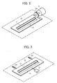
- one driving unit shown in FIG 2 includes a motor 22 attached with a gear 22a.
- the gear 22a may engage with ditches on the shutter 20 as shown in FIG 2.
- the shutter 20 can be moved in one direction when the motor 22 drives the gear 22a, engaged with the ditches of the shutter 20, in one rotational direction.
- FIG 3 Another driving unit shown in FIG 3 includes a solenoid 23 and a spring 23a to move the shutter 20.
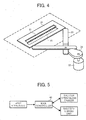
- FIG 4 another driving unit shown in FIG 4 includes the motor 22, a cam 24, and a lever 25.
- the motor 22 rotates the cam 24, and the cam 24 moves the lever 25 to move the shutter 20.
- the shutter 20 may be moved in a pivotable manner to open or close the slit 16 instead of sliding the shutter 20 in one direction.
- the shutter 20 may be connected a pivotable arm (not shown), driven by a motor.
- the optical writing unit 10 has a plurality of slits 16 to emit a plurality of light beams, a plurality of shutters 20 may be separately provided for the plurality of slits 16.
- a plurality of slits 16 may be opened or closed by one shutter as below explained.
- the shutter 20 i.e., one shutter
- the shutter 20 may have a plurality of openings 21 corresponding to the plurality of slits 16.
- the shutter 20 may open or close the plurality of openings 21 simultaneously when a driving unit (e.g., driving unit of FIGs. 2 to 4) drives the shutter 20.
- a driving unit e.g., driving unit of FIGs. 2 to 4
- FIG. 5 shows a main controller 40 for controlling the shutter 20.
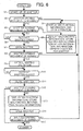
- FIG 6 is a flowchart for explaining a process of controlling a shutter-driving unit.
- the image forming apparatus 100 is activated at first.
- the image forming apparatus 100 may be supplied with power from a power source, by which the image forming apparatus 100 may be set to a power-ON condition.
- the main controller 40 instructs a start-up process such as start-up opening or closing movement of shutter and other warming-up process, as required.
- the main controller 40 checks whether the shutter 20 is in a normal opening movement with the sensors 30 and 31.
- the main controller 40 checks whether the shutter 20 is in normal closing movement with the sensors 30 and 31 at step S3.
- the main controller 40 If the main controller 40 confirms that the shutter 20 is not in a normal opening movement at step S2, the main controller 40 displays shutter-malfunction information on an operation panel, and stops an operation of the image forming apparatus 100 at step S4.
- the main controller 40 If the main controller 40 confirms that the shutter 20 is not in a normal closing movement at step S3, the main controller 40 displays shutter-malfunction information on the operation panel, and the main controller 40 stores such malfunction condition as log information in the image forming apparatus 100, and maintains an opened-condition for shutter 20 at step S5.
- the shutter 20 may not be closed in a normal manner at step S5, the shutter 20 may be maintained in an opened-condition to maintain the image forming apparatus 100 at an operable condition.
- the image forming apparatus 100 may be operable because the shutter 20 is in an opened-condition (i.e., a light beam can pass through the opening 21 and slit 16).
- a downtime of the image forming apparatus 100 may be reduced or substantially eliminated.
- the shutter 20 may not be closed in a normal manner, the shutter 20 may need to be repaired at a given time so that image quality may not be degraded due to the shutter 20, which may not be closed. Such image quality degradation may be observed as unnecessary line images on a printed image, for example.
- the shutter 20 may be repaired when a user does not use the image forming apparatus 100, for example.
- the main controller 40 confirms that the shutter 20 is in the normal closing movement at step S3, the shutter 20 is in a normal condition for opening and closing movement.
- the optical writing unit 10 may be in a standby condition, in which the optical writing unit 10 is waiting for a writing instruction.
- the main controller 40 instructs an opening of the shutter 20 at step S6, and an opening of the shutter 20 is activated at step S7.
- the main controller 40 checks whether the shutter 20 is in a normal opening movement.
- the main controller 40 confirms that the shutter 20 is in the normal opening movement at step S8, the shutter 20 is opened and the sensors 30 and 31 become ON-condition. In other words, the sensors 30 and 31 may detect that the shutter 20 is opened.
- step S9 the optical writing unit 10 conducts an optical writing operation.
- the main controller 40 confirms that the shutter 20 is not in the normal opening movement at step S8, the shutter 20 may not in an opened-conditioned, and the sensors 30 and 31 may not become ON-condition. In other words, the sensors 30 and 31 may not detect that the shutter 20 is opened.
- step S4 the main controller 40 displays shutter-malfunction information on the operation panel, and stops an operation of the image forming apparatus 100.
- the main controller 40 checks whether a close-instruction of the shutter 20 is issued at step S10.
- the main controller 40 If the main controller 40 confirms that the close-instruction of the shutter 20 is issued at step S10, the main controller 40 instructs a closing movement of the shutter 20 at step S11.
- step S12 the main controller 40 checks whether the shutter 20 is in a normal closing movement.
- the optical writing unit 10 may be set to a standby condition, in which the optical writing unit 10 may wait for a next writing instruction.
- the main controller 40 If the main controller 40 confirms that the shutter 20 is not performing the normal closing movement at step S12, the main controller 40 displays shutter-malfunction information on the operation panel, and stores such malfunction condition as log information in the image forming apparatus 100 at step S13.
- the main controller 40 opens the shutter 20 at step S14.
- the CPU checks whether the shutter 20 is performing a normal opening movement.
- the optical writing unit 10 may be set to a standby condition, in which the optical writing unit 10 may wait for a next writing instruction.
- step S15 If the main controller 40 confirms that the shutter 20 is not performing the normal opening movement at step S15, the process goes back to step S4, and the main controller 40 displays shutter-malfunction information on the operation panel, and stops an operation of the image forming apparatus 100 at step S4.
- Toners are more likely to spill over or scatter from a toner-related unit such as photosensitive member and developing member when such toner-related unit is activated or deactivated compared to a continuous operating period of the toner-related unit.
- an opening and closing timing of the shutter 20 may be synchronized with a writing operation timing of the optical writing unit 10.
- a light-beam ON signal of the optical writing unit 10 may trigger the open-instruction of the shutter 20 at step S6.
- the light-beam ON signal may be a signal generated when a light source of the optical writing unit 10 starts to emit a light beam.
- a polygon-motor ON signal may also trigger the open-instruction of the shutter 20 at step S6.
- the polygon-motor ON signal may be a signal generated when the polygon motor 11a is activated.
- a light-beam OFF signal of the optical writing unit 10 may trigger the close-instruction of the shutter 20 at step S10.
- the light-beam OFF signal may be a signal generated when the light source of the optical writing unit 10 stops emitting the light beam.
- a polygon-motor OFF signal may trigger the close-instruction of the shutter 20 at step S10.
- the polygon-motor OFF signal may be a signal generated when the polygon motor 11a is deactivated.
- the opening and closing of the shutter 20 may be triggered by the light beam ON/OFF signal or polygon motor ON/OFF signal, for example.
- the image forming apparatus 100 may include several units related to image forming operation such as photosensitive member 1 and developing unit 3, for example.
- the photosensitive member 1 or developing unit 3 may use toner particles because of their functions. Therefore, toner particles may drop from the photosensitive member 1 or developing unit 3 when the photosensitive member 1 or developing unit 3 is activated for image forming operation or deactivated after image forming operation.
- toner particles, dropped from the photosensitive member 1 or developing unit 3 may unpreferably contaminate dustproof glass of the slit 16, and similarly, if the shutter 20 is closed after the photosensitive member 1 or developing unit 3 is deactivated, toner particles, dropped from the photosensitive member 1 or developing unit 3, may unpreferably contaminate the dustproof glass of the slit 16.
- the light-beam ON signal or polygon-motor ON signal may be generated after the photosensitive member 1 or developing unit 3 is activated, and such light-beam ON signal or polygon-motor ON signal may be used as a trigger signal for opening the shutter 20.
- the shutter 20 may be opened after the photosensitive member 1 or developing unit 3 is activated, by which a contamination of the dustproof glass of the slit 16 by dropping toner particles may be suppressed.
- the light-beam OFF signal or polygon-motor OFF signal may be generated before the photosensitive member 1 or developing unit 3 is deactivated, and such light-beam OFF signal or polygon-motor OFF signal may be used as a trigger signal for closing the shutter 20.
- the shutter 20 may be closed before the photosensitive member 1 or developing unit 3 is deactivated, by which a contamination of the dustproof glass of the slit 16 by dropping toner particles may be suppressed.
- setting and using the light beam ON/OFF signal or polygon motor ON/OFF signal as trigger signal for opening or closing the shutter 20 in the above-explained manner may preferably suppress a contamination of the dustproof glass of the slit 16.
- the open-instruction of the shutter 20 at the step S6 may be triggered by signals transmitted from a sensor (e.g., ON/OFF signal) or an operation start signal to be generated in a controller such as main controller 40.
- a sensor e.g., ON/OFF signal
- an operation start signal may be generated as software instruction for the main controller 40, for example.
- the operation start signal may instruct an activation of the optical writing unit 10, for example.
- the opening of the shutter 20 may be preferably conducted in a stable manner.
- the image forming apparatus 100 may conduct a preliminary operation for checking a writing position by the optical writing unit 10 with a light beam before conducting an actual image forming.
- a signal, which detects such preliminary operation, may be used as a trigger signal, by which a condition of the shutter 20 may be changed from closed-condition to opened-condition.
- toners may be more likely to spill over or scatter when unexpected shock occurs to the image forming apparatus 100.
- Such unexpected shock may be likely to occur when a cover, a sheet transporter guide plate or the like of the image forming apparatus 100 is opened or closed for some reasons such as sheet-jamming correction and maintenance work, for example.
- an opening and closing process of the shutter 20 may be conducted with a flowchart shown in FIG. 7.
- the flowchart shown in FIG 7 has similar steps shown in FIG 6 such as steps S1 to S9 and steps S11 to S15, and the explanation for such steps are omitted from the following explanation.
- the main controller 40 checks whether a cover sensor becomes ON condition.
- a cover of the image forming apparatus 100 may be opened.
- the cover may include any kinds cover or the like such as outer cover, sheet transporter guide plate, for example.
- the main controller 40 If the main controller 40 confirms that the cover sensor is ON condition at step S10a, the main controller 40 advances the process to steps S11 to S15 as similar to FIG 6.
- step S10a If the main controller 40 confirms that the cover sensor is not ON condition at step S10a (i.e., no cover is opened), the main controller 40 advances the process to step S10 in FIG 6. After the step S10, the main controller 40 advances the process to steps S11 to S15.
- the cover sensor may be in ON condition. Then the shutter 20 is closed with the process shown in FIG 7.
- foreign materials e.g., toner
- optical parts e.g., dustproof glass
- malfunction information may be related to a malfunction of shutter and shutter-related parts for driving the shutter.
- malfunction information may also be related to other parts, which is not related to the shutter and shutter-related parts.
- a process of opening and closing the shutter which includes malfunctioned condition of other parts, may be conducted in a similar manner as to the above-described process explained with FIG 7, as required.
Landscapes
- Physics & Mathematics (AREA)
- General Physics & Mathematics (AREA)
- Engineering & Computer Science (AREA)
- Multimedia (AREA)
- Signal Processing (AREA)
- Facsimile Scanning Arrangements (AREA)
- Mechanical Optical Scanning Systems (AREA)
- Exposure Or Original Feeding In Electrophotography (AREA)
- Control Or Security For Electrophotography (AREA)
- Laser Beam Printer (AREA)
- Optical Systems Of Projection Type Copiers (AREA)
Abstract
Description
- The present disclosure generally relates to an optical scanning unit for an image forming apparatus, and such an image forming apparatus, and more particularly to an optical scanning unit having a shutter and a driving unit for opening and closing a light-beam emitting aperture.
- In a market of image forming apparatus such as laser printer and digital copier, an increased demand is voiced in many features of image forming apparatus such as enhanced image quality, enhanced image-forming speed, further miniaturization of apparatus, and enhanced energy saving, for example.
- In view of such trends, an optical writing unit has been employing optical parts having a higher quality and higher performance. Such optical parts may include a light source, which irradiates a light beam to an image-carrying member, for example.
- In some image forming apparatus, an optical scanning unit having a light-beam emitting aperture may be disposed under the photosensitive unit.
- In such image forming apparatus, when toners spill over or scatter from a photosensitive unit, developing unit, and cleaning unit, such spilled toners may intrude into the optical scanning unit through the light-beam emitting aperture.
- Accordingly, the light-beam emitting aperture may be covered with a transparent dustproof member such as a glass plate to prevent an intrusion of foreign materials (e.g., toner) into the optical scanning unit through the light-beam emitting aperture.
- Such configurations may prevent an intrusion of foreign materials into the optical scanning unit, but foreign materials (e.g., toner) may adhere on the dustproof glass, which may lead to a degradation of image quality.
- In related image forming apparatus, an optical scanning unit may include a shutter over a transparent member (e.g., dustproof glass) so that the transparent member may not be contaminated with foreign materials (e.g., toner).
- Such shutters may block toner adhesion to the transparent member (e.g., dustproof glass), which may be effective for preventing contamination of dustproof glass.
- In one related art, such a shutter may be in an opened-condition before starting a developing process for a latent image on the photosensitive unit, and the shutter may be closed just before a completion of the developing process on the photosensitive unit.
- In another related art, such a shutter may be set to an opened-condition when a given time has lapsed after a synchronous-detecting marking on a photosensitive unit is detected, and the shutter may move into a closed-condition when a given time has lapsed after a writing operation in a sub-scanning direction has completed.
- However, if the shutter is closed before completing the developing process on the photosensitive member (i.e., the shutter is closed at a wrong timing), a latent image may not be correctly developed on the photosensitive member.
- Furthermore, if the shutter moves into a closed-condition when a given time has lapsed after a writing operation in a sub-scanning direction has completed, the shutter may be in an opened-condition for a time period between a completion of writing operation and a complete closing of the shutter.
- In such cases, foreign materials (e.g., toner), dropped by unexpected external shock, may contaminate optical parts related to light beam transmission of the optical scanning unit such as dustproof glass via the above-mentioned still-opened shutter.
- At least one embodiment of the present disclosure relates to an optical scanning unit of an image forming apparatus. Such an optical scanning unit includes an optical housing including at least one optical part and a light-beam emitting aperture through which a light beam can emanate from the optical housing; a shutter configured to cover the light-beam emitting aperture; and a driving unit configured to drive the shutter to open and close the light-beam emitting aperture.
- The driving unit is further operable to coordinate at least one of the opening and the closing to occur after activation and before deactivation of a writing operation conducted by the optical scanning unit, respectively.
- A more complete appreciation of the disclosure and many of the attendant advantages and features thereof can be readily obtained and understood from the following detailed description with reference to the accompanying drawings, wherein:
- FIG 1 is a schematic view an image forming apparatus according to an example embodiment;
- FIGs. 2, 3, and 4 are perspective views of example shutter-driving units for use in an image forming apparatus of FIG 1;
- FIG 5 is a block diagram for controlling a shutter-driving unit;
- FIG 6 is a flowchart for explaining a process of controlling a shutter-driving unit; and
- FIG 7 is a flowchart for explaining another process of controlling a shutter-driving unit.
- In describing example embodiments shown in the drawings, specific terminology is employed for the sake of clarity. However, the present disclosure is not intended to be limited to the specific terminology so selected and it is to be understood that each specific element includes all technical equivalents that operate in a similar manner.
- Referring now to the drawings, wherein like reference numerals designate identical or corresponding parts throughout the several views, an image forming apparatus including an optical writing unit according to an example embodiment is described with particular reference to FIG 1.
- FIG 1 is a schematic view of an
image forming apparatus 100 including an optical writing unit according to an example embodiment. - As shown in FIG 1, the
image forming apparatus 100 may include aphotosensitive member 1, acharger 2, a developingunit 3, atransfer unit 4, acleaning unit 5, and anoptical writing unit 10, for example. - The
photosensitive member 1 may rotate in a counter-clockwise direction in FIG 1 by a driver (not shown), for example. - The
charger 2 uniformly charges a surface of thephotosensitive member 1 when thephotosensitive member 1 is rotating. - Then, a light beam, emitted from the
optical writing unit 10 irradiates the charged surface of thephotosensitive member 1 so that an electrostatic latent image is formed on thephotosensitive member 1. - The developing
unit 3 develops the electrostatic latent image on thephotosensitive member 1 as toner image. - The
transfer unit 4 transfers the toner image from thephotosensitive member 1 to a transfer sheet (not shown). The transfer sheet can be transported from a sheet feed unit (not shown) to thephotosensitive member 1 by a sheet transporter. The sheet transporter may have a sheet transporter guide plate to align the transfer sheet in a correct orientation. - After transferring the toner image to the transfer sheet from the
photosensitive member 1, a fixing unit (not shown) fixes the toner image on the transfer sheet, and then the transfer sheet is ejected from theimage forming apparatus 100. - After transferring the toner image to the transfer sheet from the
photosensitive member 1, thecleaning unit 5 removes toner particles remaining on thephotosensitive member 1. - In the
optical writing unit 10, a light beam emitted from a light source (not shown) such as semiconductor laser goes through a collimator lens, a spherical lens, and a cylindrical lens, and enters apolygon mirror 11. Thepolygon mirror 11 may be rotated by apolygon motor 11a. - The light beam deflected by the
polygon mirror 11 goes through a f-theta lens 12, and reflects atmirrors slit 16. Theslit 16 may be used as light-beam emitting aperture. - Then, the light beam goes to the
photosensitive member 1, and scans a surface ofphotosensitive member 1 in an axial direction (or main scanning direction) of thephotosensitive member 1. - In general, a transparent member such as dustproof glass may cover the
slit 16 to prevent intrusion of foreign materials (e.g., toner) into theoptical writing unit 10. - As shown in FIG 1, a
shutter 20 is provided between theoptical writing unit 10 andphotosensitive member 1. Theshutter 20 may be formed into a plate shape, for example. - In an example embodiment, the
shutter 20 may include anopening 21 as shown in FIG 1. - When the opening 21 and
slit 16 are aligned in a light beam direction, theshutter 20 may be in an opened-condition, and when the opening 21 andslit 16 are not aligned in a light beam direction, theshutter 20 may be in a closed-condition. -
Sensors shutter 20. - As shown in FIG 1, the
shutter 20 may be slidably moved in a direction shown by an arrow A by a driving unit (see FIGs. 2, 3, and 4) so that theshutter 20 can be set to an opened or closed-condition. - The driving unit for the
shutter 20 may include several types as shown in FIGs. 2 to 4, for example. - Specifically, one driving unit shown in FIG 2 includes a
motor 22 attached with agear 22a. Thegear 22a may engage with ditches on theshutter 20 as shown in FIG 2. Theshutter 20 can be moved in one direction when themotor 22 drives thegear 22a, engaged with the ditches of theshutter 20, in one rotational direction. - Furthermore, another driving unit shown in FIG 3 includes a
solenoid 23 and aspring 23a to move theshutter 20. - Furthermore, another driving unit shown in FIG 4 includes the
motor 22, acam 24, and alever 25. Themotor 22 rotates thecam 24, and thecam 24 moves thelever 25 to move theshutter 20. - Although not shown, the
shutter 20 may be moved in a pivotable manner to open or close theslit 16 instead of sliding theshutter 20 in one direction. In such pivotable configuration, theshutter 20 may be connected a pivotable arm (not shown), driven by a motor. - If the
optical writing unit 10 has a plurality ofslits 16 to emit a plurality of light beams, a plurality ofshutters 20 may be separately provided for the plurality ofslits 16. - However, a plurality of
slits 16 may be opened or closed by one shutter as below explained. - For example, if the
optical writing unit 10 has a plurality ofslits 16, the shutter 20 (i.e., one shutter) may have a plurality ofopenings 21 corresponding to the plurality ofslits 16. - In such configuration, the
shutter 20 may open or close the plurality ofopenings 21 simultaneously when a driving unit (e.g., driving unit of FIGs. 2 to 4) drives theshutter 20. - Hereinafter, a process for opening or closing of the
shutter 20 is explained with reference to FIGs. 5 and 6. - FIG. 5 shows a
main controller 40 for controlling theshutter 20. FIG 6 is a flowchart for explaining a process of controlling a shutter-driving unit. - In FIG 6, the
image forming apparatus 100 is activated at first. For example, theimage forming apparatus 100 may be supplied with power from a power source, by which theimage forming apparatus 100 may be set to a power-ON condition. - At step S1, the
main controller 40 instructs a start-up process such as start-up opening or closing movement of shutter and other warming-up process, as required. - At step S2, the
main controller 40 checks whether theshutter 20 is in a normal opening movement with thesensors - If the
main controller 40 confirms that theshutter 20 is in a normal opening movement at step S2, themain controller 40 checks whether theshutter 20 is in normal closing movement with thesensors - If the
main controller 40 confirms that theshutter 20 is not in a normal opening movement at step S2, themain controller 40 displays shutter-malfunction information on an operation panel, and stops an operation of theimage forming apparatus 100 at step S4. - If the
main controller 40 confirms that theshutter 20 is not in a normal closing movement at step S3, themain controller 40 displays shutter-malfunction information on the operation panel, and themain controller 40 stores such malfunction condition as log information in theimage forming apparatus 100, and maintains an opened-condition forshutter 20 at step S5. - Although the
shutter 20 may not be closed in a normal manner at step S5, theshutter 20 may be maintained in an opened-condition to maintain theimage forming apparatus 100 at an operable condition. - Specifically, the
image forming apparatus 100 may be operable because theshutter 20 is in an opened-condition (i.e., a light beam can pass through theopening 21 and slit 16). - By operating the
image forming apparatus 100 under such condition, a downtime of theimage forming apparatus 100 may be reduced or substantially eliminated. - Because the
shutter 20 may not be closed in a normal manner, theshutter 20 may need to be repaired at a given time so that image quality may not be degraded due to theshutter 20, which may not be closed. Such image quality degradation may be observed as unnecessary line images on a printed image, for example. - The
shutter 20 may be repaired when a user does not use theimage forming apparatus 100, for example. - If the
main controller 40 confirms that theshutter 20 is in the normal closing movement at step S3, theshutter 20 is in a normal condition for opening and closing movement. - During such a process, the
optical writing unit 10 may be in a standby condition, in which theoptical writing unit 10 is waiting for a writing instruction. - If the writing instruction is issued, the
main controller 40 instructs an opening of theshutter 20 at step S6, and an opening of theshutter 20 is activated at step S7. - At step S8, the
main controller 40 checks whether theshutter 20 is in a normal opening movement. - If the
main controller 40 confirms that theshutter 20 is in the normal opening movement at step S8, theshutter 20 is opened and thesensors sensors shutter 20 is opened. - Then, at step S9, the
optical writing unit 10 conducts an optical writing operation. - If the
main controller 40 confirms that theshutter 20 is not in the normal opening movement at step S8, theshutter 20 may not in an opened-conditioned, and thesensors sensors shutter 20 is opened. - Then, the process goes back to step S4, at which the
main controller 40 displays shutter-malfunction information on the operation panel, and stops an operation of theimage forming apparatus 100. - When the
optical writing unit 10 completes the optical writing at step S9, themain controller 40 checks whether a close-instruction of theshutter 20 is issued at step S10. - If the
main controller 40 confirms that the close-instruction of theshutter 20 is issued at step S10, themain controller 40 instructs a closing movement of theshutter 20 at step S11. - Then, at step S12, the
main controller 40 checks whether theshutter 20 is in a normal closing movement. - If the
main controller 40 confirms that theshutter 20 is performing the normal closing movement at step S12, theoptical writing unit 10 may be set to a standby condition, in which theoptical writing unit 10 may wait for a next writing instruction. - If the
main controller 40 confirms that theshutter 20 is not performing the normal closing movement at step S12, themain controller 40 displays shutter-malfunction information on the operation panel, and stores such malfunction condition as log information in theimage forming apparatus 100 at step S13. - Then, the
main controller 40 opens theshutter 20 at step S14. - At step S15, the CPU checks whether the
shutter 20 is performing a normal opening movement. - If the
main controller 40 confirms that theshutter 20 is performing the normal opening movement at step S15, theoptical writing unit 10 may be set to a standby condition, in which theoptical writing unit 10 may wait for a next writing instruction. - If the
main controller 40 confirms that theshutter 20 is not performing the normal opening movement at step S15, the process goes back to step S4, and themain controller 40 displays shutter-malfunction information on the operation panel, and stops an operation of theimage forming apparatus 100 at step S4. - Toners are more likely to spill over or scatter from a toner-related unit such as photosensitive member and developing member when such toner-related unit is activated or deactivated compared to a continuous operating period of the toner-related unit.
- Therefore, in an example embodiment, an opening and closing timing of the
shutter 20 may be synchronized with a writing operation timing of theoptical writing unit 10. - Specifically, a light-beam ON signal of the
optical writing unit 10 may trigger the open-instruction of theshutter 20 at step S6. The light-beam ON signal may be a signal generated when a light source of theoptical writing unit 10 starts to emit a light beam. - Furthermore, a polygon-motor ON signal may also trigger the open-instruction of the
shutter 20 at step S6. The polygon-motor ON signal may be a signal generated when thepolygon motor 11a is activated. - Similarly, a light-beam OFF signal of the
optical writing unit 10 may trigger the close-instruction of theshutter 20 at step S10. The light-beam OFF signal may be a signal generated when the light source of theoptical writing unit 10 stops emitting the light beam. - Furthermore, a polygon-motor OFF signal may trigger the close-instruction of the
shutter 20 at step S10. The polygon-motor OFF signal may be a signal generated when thepolygon motor 11a is deactivated. - As such, the opening and closing of the
shutter 20 may be triggered by the light beam ON/OFF signal or polygon motor ON/OFF signal, for example. - As above-mentioned, the
image forming apparatus 100 may include several units related to image forming operation such asphotosensitive member 1 and developingunit 3, for example. - In general, the
photosensitive member 1 or developingunit 3 may use toner particles because of their functions. Therefore, toner particles may drop from thephotosensitive member 1 or developingunit 3 when thephotosensitive member 1 or developingunit 3 is activated for image forming operation or deactivated after image forming operation. - For example, if the
shutter 20 is opened before thephotosensitive member 1 or developingunit 3 is activated, toner particles, dropped from thephotosensitive member 1 or developingunit 3, may unpreferably contaminate dustproof glass of theslit 16, and similarly, if theshutter 20 is closed after thephotosensitive member 1 or developingunit 3 is deactivated, toner particles, dropped from thephotosensitive member 1 or developingunit 3, may unpreferably contaminate the dustproof glass of theslit 16. - In view of such background, the light-beam ON signal or polygon-motor ON signal may be generated after the
photosensitive member 1 or developingunit 3 is activated, and such light-beam ON signal or polygon-motor ON signal may be used as a trigger signal for opening theshutter 20. In such configuration, theshutter 20 may be opened after thephotosensitive member 1 or developingunit 3 is activated, by which a contamination of the dustproof glass of theslit 16 by dropping toner particles may be suppressed. - Furthermore, the light-beam OFF signal or polygon-motor OFF signal may be generated before the
photosensitive member 1 or developingunit 3 is deactivated, and such light-beam OFF signal or polygon-motor OFF signal may be used as a trigger signal for closing theshutter 20. In such configuration, theshutter 20 may be closed before thephotosensitive member 1 or developingunit 3 is deactivated, by which a contamination of the dustproof glass of theslit 16 by dropping toner particles may be suppressed. - Accordingly, setting and using the light beam ON/OFF signal or polygon motor ON/OFF signal as trigger signal for opening or closing the
shutter 20 in the above-explained manner may preferably suppress a contamination of the dustproof glass of theslit 16. - The open-instruction of the
shutter 20 at the step S6 may be triggered by signals transmitted from a sensor (e.g., ON/OFF signal) or an operation start signal to be generated in a controller such asmain controller 40. Specifically, such an operation start signal may be generated as software instruction for themain controller 40, for example. The operation start signal may instruct an activation of theoptical writing unit 10, for example. - Compared to signals transmitted from a sensor or the like, which may be more likely to be affected by electronic noises from environment, such software instruction may be less likely to be affected by electronic noises from environment.
- Accordingly, if such software instruction may be used as trigger signal for opening the
shutter 20, the opening of theshutter 20 may be preferably conducted in a stable manner. - Furthermore, the
image forming apparatus 100 may conduct a preliminary operation for checking a writing position by theoptical writing unit 10 with a light beam before conducting an actual image forming. - A signal, which detects such preliminary operation, may be used as a trigger signal, by which a condition of the
shutter 20 may be changed from closed-condition to opened-condition. - As above-mentioned, toners may be more likely to spill over or scatter when unexpected shock occurs to the
image forming apparatus 100. - Specifically, such unexpected shock may be likely to occur when a cover, a sheet transporter guide plate or the like of the
image forming apparatus 100 is opened or closed for some reasons such as sheet-jamming correction and maintenance work, for example. - In view of such unexpected shock, which may occur to the
image forming apparatus 100, an opening and closing process of theshutter 20 may be conducted with a flowchart shown in FIG. 7. - The flowchart shown in FIG 7 has similar steps shown in FIG 6 such as steps S1 to S9 and steps S11 to S15, and the explanation for such steps are omitted from the following explanation.
- As shown in FIG. 7, at step S10a, the
main controller 40 checks whether a cover sensor becomes ON condition. When the cover sensor is ON condition, a cover of theimage forming apparatus 100 may be opened. The cover may include any kinds cover or the like such as outer cover, sheet transporter guide plate, for example. - If the
main controller 40 confirms that the cover sensor is ON condition at step S10a, themain controller 40 advances the process to steps S11 to S15 as similar to FIG 6. - If the
main controller 40 confirms that the cover sensor is not ON condition at step S10a (i.e., no cover is opened), themain controller 40 advances the process to step S10 in FIG 6. After the step S10, themain controller 40 advances the process to steps S11 to S15. - As such, when the
shutter 20 is in an opened-condition, the cover sensor may be in ON condition. Then theshutter 20 is closed with the process shown in FIG 7. - Accordingly, foreign materials (e.g., toner) may not contaminate optical parts (e.g., dustproof glass) of the
optical writing unit 10 even if a shock or vibration may occur to theimage forming apparatus 100 by opening the cover for some reasons such as jammed-sheet removal and maintenance work, for example. - In the above-described embodiment, malfunction information may be related to a malfunction of shutter and shutter-related parts for driving the shutter. However, malfunction information may also be related to other parts, which is not related to the shutter and shutter-related parts.
- Accordingly, a process of opening and closing the shutter, which includes malfunctioned condition of other parts, may be conducted in a similar manner as to the above-described process explained with FIG 7, as required.
- Numerous additional modifications and variations are possible in light of the above teachings. It is therefore to be understood that within the scope of the appended claims, the disclosure of the present invention may be practiced otherwise than as specifically described herein.
- This application claims priority from
Japanese patent application No. 2005-346035 filed on November 30, 2005
Claims (21)
- An optical scanning unit of an image forming apparatus (100), the optical scanning unit comprising:an optical housing (10) configured to include at least one optical part (11, 12, 13, 14, 15) and to have a light-beam emitting aperture (16) through which a light beam can emanate from the optical housing;a shutter (20) configured to selectively close and open the light-beam emitting aperture; anda driving unit (22, 22a; 23, 23a; 24, 25) configured to drive the shutter to open and close the light-beam emitting aperture;the driving unit being operable to coordinate at least one of the opening and the closing to occur after activation and before deactivation of a writing operation conducted by the optical scanning unit, respectively.
- An optical scanning unit according to claim 1, wherein the driving unit is configured to open the shutter by using, as a trigger signal, at least one of the following:a light-beam ON signal of the optical scanning unit; anda polygon-motor ON signal of the optical scanning unit.
- An optical scanning unit according to claim 1 or 2, wherein the driving unit is configured to close the shutter by using, as a trigger signal, at least one of the following:a light-beam OFF signal of the optical scanning unit; anda polygon-motor OFF signal of the optical scanning unit.
- An optical scanning unit according to any preceding claim, wherein the driving unit is configured to open the shutter using, as a trigger signal, at least one of the following:a signal generated when checking a writing position by the optical scanning unit; anda signal generated by software to start operation of the optical scanning unit.
- An optical scanning unit according to claim 1, wherein the driving unit is configured to close the shutter when a malfunction of a first type part in the image forming apparatus is detected, and wherein the first type part includes a part which is not related for configuring and driving the shutter.
- An optical scanning unit according to claim 5, wherein the driving unit is configured to close the shutter when a malfunction occurs to a sheet transporter of the image forming apparatus, and wherein the sheet transporter is included in the first type part.
- An optical scanning unit according to claim 5, wherein the driving unit is configured to close the shutter when an opening of any one of a cover and sheet transporter guide plate of the image forming is detected, and wherein the cover and a sheet transporter guide plate are included in the first type part.
- An optical scanning unit according to any preceding claim, wherein the driving unit is configured to open the shutter when a malfunction of a second type part in the image forming apparatus is detected, and wherein the second type part includes the shutter and a part, which is related for configuring and driving the shutter.
- An optical scanning unit according to claim 8, wherein the image forming apparatus is configured to display malfunction information of the second type part on an operation unit when the malfunction of the second type part is detected and the shutter is opened.
- An optical scanning unit according to claim 8, wherein the image forming apparatus is configured to store malfunction information of the second type part as log information when the malfunction of the second type part is detected and the shutter is opened.
- An optical scanning unit of an image forming apparatus (100), the optical scanning unit, comprising:housing means (10) for housing at least one optical part (11, 12, 13, 14, 15) and having a light-beam emitting aperture (16) through which a light beam can emanate from the housing means;shuttering means (20) for shuttering the light-beam emitting aperture;driving means (22, 22a; 23, 23a; 24, 25) for driving the shuttering means thus selectively opening and closing the light-beam emitting aperture;the driving means further being for coordinating at least one of the opening and the closing to occur after activation and before deactivation of a writing operation conducted by the optical scanning unit, respectively.
- A method of operating an optical scanning unit of an image forming apparatus (100), the optical scanning unit including an optical housing (10) configured to include at least one optical part (11, 12, 13, 14, 15) and to have a light-beam emitting aperture (16) through which a light beam can emanate from the optical housing, a shutter (20) to selectively close and open the light-beam emitting aperture, and a driving unit (22, 22a; 23, 23a; 24, 25) configured to drive the shutter, the method comprising:controlling the driving unit to drive the shutter to open and close the light-beam emitting aperture; andcoordinating at least one of the opening and the closing to occur after activation and before deactivation of a writing operation conducted by the optical scanning unit, respectively.
- A method according to claim 12, further comprising:using, as a trigger signal to cause opening of the shutter when the same is in a closed-condition, at least one of the following:a light-beam ON signal of the optical scanning unit;a polygon-motor ON signal of the optical scanning unit;a signal generated when checking a writing position by the optical scanning unit, anda signal generated by software to start operation of the optical scanning unit.
- A method according to claim 12 or 13, further comprising:using, as a trigger signal to cause closing of the shutter when the same is in an opened-condition, at least one of the following:a light-beam OFF signal of the optical scanning unit, anda polygon-motor OFF signal of the optical scanning unit.
- A method according to any of claims 12 to 14, further comprising:closing the shutter when a malfunction of a first type part in the mage forming apparatus is detected, and wherein the first type part includes a part which is not related for configuring and driving the shutter.
- A method according to claim 15, wherein the first type part is a sheet transporter.
- A method according to claim 15, wherein:the first type part includes at least one of a cover and a sheet transporter guide plate; andthe malfunction includes opening at least one of the cover and the sheet transporter guide plate, respectively.
- A method according to any of claims 12 to 17, further comprising:closing the shutter when a malfunction of a second type part in the image forming apparatus is detected, and wherein the second type part includes the shutter and a part which is not related for configuring and driving the shutter.
- A method according to claim 18, further comprising:displaying malfunction information of the second type part on an operation unit when the malfunction of the second type part is detected and the shutter is opened.
- A method according to claim 18 or 19, further comprising:storing malfunction information of the second type part as log information when the malfunction of the second type part is detected and the shutter is opened.
- An image forming apparatus (100) comprising an optical scanning unit according to any of claims 1 to 11.
Applications Claiming Priority (1)
| Application Number | Priority Date | Filing Date | Title |
|---|---|---|---|
| JP2005346035A JP2007144951A (en) | 2005-11-30 | 2005-11-30 | Image forming apparatus |
Publications (3)
| Publication Number | Publication Date |
|---|---|
| EP1792738A2 true EP1792738A2 (en) | 2007-06-06 |
| EP1792738A3 EP1792738A3 (en) | 2009-09-30 |
| EP1792738B1 EP1792738B1 (en) | 2014-10-01 |
Family
ID=37806249
Family Applications (1)
| Application Number | Title | Priority Date | Filing Date |
|---|---|---|---|
| EP06256103.0A Not-in-force EP1792738B1 (en) | 2005-11-30 | 2006-11-29 | Image forming apparatus and method of operating it |
Country Status (4)
| Country | Link |
|---|---|
| US (1) | US7869101B2 (en) |
| EP (1) | EP1792738B1 (en) |
| JP (1) | JP2007144951A (en) |
| CN (1) | CN1983057B (en) |
Families Citing this family (13)
| Publication number | Priority date | Publication date | Assignee | Title |
|---|---|---|---|---|
| JP2008216438A (en) * | 2007-03-01 | 2008-09-18 | Ricoh Co Ltd | Optical scanning apparatus and image forming apparatus |
| JP5016997B2 (en) * | 2007-07-02 | 2012-09-05 | 株式会社リコー | Optical scanning apparatus and image forming apparatus |
| JP4887268B2 (en) * | 2007-12-13 | 2012-02-29 | 株式会社リコー | Curvature correction mechanism, optical scanning device, and image forming apparatus |
| JP2010284912A (en) * | 2009-06-12 | 2010-12-24 | Ricoh Co Ltd | Writing apparatus, control method, and image forming apparatus |
| JP5240576B2 (en) * | 2009-06-19 | 2013-07-17 | 株式会社リコー | Optical scanning apparatus and image forming apparatus |
| JP5495104B2 (en) * | 2009-10-16 | 2014-05-21 | ウシオ電機株式会社 | Inspection equipment using chips |
| CN102991156B (en) * | 2011-09-19 | 2015-04-22 | 深圳市证通电子股份有限公司 | Printer |
| KR101838632B1 (en) * | 2011-12-28 | 2018-03-15 | 에스프린팅솔루션 주식회사 | Image forming apparatus |
| JP5903894B2 (en) | 2012-01-06 | 2016-04-13 | 株式会社リコー | Optical scanning apparatus and image forming apparatus |
| JP6435805B2 (en) | 2014-11-20 | 2018-12-12 | 株式会社リコー | Housing structure, optical scanning device, and image forming apparatus |
| US9851654B2 (en) * | 2016-05-02 | 2017-12-26 | Lexmark International, Inc. | Automated lens cleaning and shutter system for an electrophotographic imaging device |
| JP7143176B2 (en) * | 2018-10-04 | 2022-09-28 | キヤノン株式会社 | image forming device |
| JP2025009390A (en) * | 2023-07-07 | 2025-01-20 | 株式会社リコー | Post-processing device and image forming system |
Family Cites Families (24)
| Publication number | Priority date | Publication date | Assignee | Title |
|---|---|---|---|---|
| JPS60242486A (en) * | 1984-05-17 | 1985-12-02 | Canon Inc | Recorder |
| JP2872717B2 (en) * | 1989-12-07 | 1999-03-24 | 株式会社リコー | Recording device |
| JPH04288772A (en) * | 1991-02-27 | 1992-10-13 | Mitsubishi Electric Corp | Color image processor |
| JPH04283772A (en) * | 1991-03-12 | 1992-10-08 | Ricoh Co Ltd | Image forming device and image forming method |
| JPH04366868A (en) | 1991-06-14 | 1992-12-18 | Ricoh Co Ltd | Image forming device |
| JPH0767373A (en) * | 1993-08-24 | 1995-03-10 | Mita Ind Co Ltd | Motor controller |
| DE69726506T2 (en) * | 1996-01-10 | 2004-11-04 | Kabushiki Kaisha Topcon | ARRANGEMENT ASSESSMENT DEVICE AND SYSTEM |
| JPH09244362A (en) * | 1996-03-06 | 1997-09-19 | Canon Inc | Recording device |
| JPH10250145A (en) | 1997-03-14 | 1998-09-22 | Ricoh Co Ltd | Image forming device |
| JPH11218707A (en) * | 1998-02-04 | 1999-08-10 | Canon Inc | Scanning optical device |
| JPH11227249A (en) | 1998-02-16 | 1999-08-24 | Ricoh Co Ltd | Image forming apparatus |
| JP3668022B2 (en) | 1998-11-16 | 2005-07-06 | 株式会社リコー | Image forming apparatus |
| JP2000263839A (en) * | 1999-03-11 | 2000-09-26 | Fuji Xerox Co Ltd | Image-forming apparatus |
| US6593951B2 (en) | 2000-09-25 | 2003-07-15 | Ricoh Company, Ltd. | Optical writing system directed to miniaturization thereof, and image forming apparatus employing it |
| JP4585684B2 (en) * | 2000-12-04 | 2010-11-24 | 株式会社オーク製作所 | Acousto-optic device stationary system in laser beam lithography system |
| JP2002351287A (en) * | 2001-03-23 | 2002-12-06 | Ricoh Co Ltd | Image forming unit and image forming apparatus |
| JP4386325B2 (en) | 2001-09-21 | 2009-12-16 | 株式会社リコー | Image forming apparatus |
| JP2003246128A (en) * | 2002-02-26 | 2003-09-02 | Canon Inc | Image forming device |
| JP4008262B2 (en) | 2002-02-28 | 2007-11-14 | 株式会社リコー | Image forming apparatus |
| JP4225838B2 (en) | 2003-06-03 | 2009-02-18 | 株式会社リコー | Laser writing apparatus and image forming apparatus |
| ES2271921T3 (en) * | 2003-09-18 | 2007-04-16 | Ricoh Company, Ltd. | PREVENT THE ENTRY OF TONER POWDER AND DUST DISPERSED IN AN OPTICAL WRITING DEVICE. |
| JP4416468B2 (en) * | 2003-10-03 | 2010-02-17 | キヤノン株式会社 | Image forming apparatus |
| US7312262B2 (en) | 2004-03-22 | 2007-12-25 | Donelson Construction Co., Llc | Methods and compositions for microsurfacing |
| JP4130917B2 (en) * | 2004-04-28 | 2008-08-13 | シャープ株式会社 | Exposure apparatus and image forming apparatus |
-
2005
- 2005-11-30 JP JP2005346035A patent/JP2007144951A/en active Pending
-
2006
- 2006-11-29 EP EP06256103.0A patent/EP1792738B1/en not_active Not-in-force
- 2006-11-29 US US11/605,267 patent/US7869101B2/en not_active Expired - Fee Related
- 2006-11-30 CN CN200610063941.5A patent/CN1983057B/en not_active Expired - Fee Related
Also Published As
| Publication number | Publication date |
|---|---|
| US20070134023A1 (en) | 2007-06-14 |
| EP1792738A3 (en) | 2009-09-30 |
| CN1983057B (en) | 2010-08-25 |
| EP1792738B1 (en) | 2014-10-01 |
| US7869101B2 (en) | 2011-01-11 |
| JP2007144951A (en) | 2007-06-14 |
| CN1983057A (en) | 2007-06-20 |
Similar Documents
| Publication | Publication Date | Title |
|---|---|---|
| EP1792738B1 (en) | Image forming apparatus and method of operating it | |
| JP3156239B2 (en) | Process cartridge and image forming apparatus | |
| JP4187672B2 (en) | Light beam scanning unit and image forming apparatus | |
| JP2010284912A (en) | Writing apparatus, control method, and image forming apparatus | |
| US6931229B2 (en) | Apparatus and method of forming image using rotary developer | |
| JP4871577B2 (en) | Optical scanning apparatus and image forming apparatus | |
| EP1550917B1 (en) | Image formation device enabling switching between color printing mode and monochrome printing mode | |
| JP2005329622A (en) | Optical writing apparatus and image forming apparatus | |
| US8525863B2 (en) | Optical scanning device and image forming apparatus | |
| US8351826B2 (en) | Image forming method, image forming device, and image forming program | |
| US5812180A (en) | Laser recording apparatus which maintains the laser recording unit in a horizontal position | |
| JP2002070956A (en) | Driving gear and picture forming device using this driving gear | |
| JP2010139610A (en) | Optical scanner and image forming apparatus | |
| EP2492760B1 (en) | Image forming apparatus | |
| JP7443902B2 (en) | optical writing device | |
| JP2007171509A (en) | Image forming apparatus | |
| JP2010072418A (en) | Image forming apparatus | |
| JP2001066540A (en) | Optical scanning device and image forming apparatus | |
| JP2025181061A (en) | Image forming device | |
| JP2000147417A (en) | Scanning exposure equipment | |
| JP4251547B2 (en) | Image forming apparatus | |
| JP2007144853A (en) | Optical scanning apparatus and image forming apparatus | |
| JP2005121750A (en) | Image reading apparatus and image forming apparatus | |
| JP5089623B2 (en) | Image forming apparatus | |
| JPH06328771A (en) | Image recording apparatus |
Legal Events
| Date | Code | Title | Description |
|---|---|---|---|
| PUAI | Public reference made under article 153(3) epc to a published international application that has entered the european phase |
Free format text: ORIGINAL CODE: 0009012 |
|
| 17P | Request for examination filed |
Effective date: 20061206 |
|
| AK | Designated contracting states |
Kind code of ref document: A2 Designated state(s): AT BE BG CH CY CZ DE DK EE ES FI FR GB GR HU IE IS IT LI LT LU LV MC NL PL PT RO SE SI SK TR |
|
| AX | Request for extension of the european patent |
Extension state: AL BA HR MK YU |
|
| PUAL | Search report despatched |
Free format text: ORIGINAL CODE: 0009013 |
|
| AK | Designated contracting states |
Kind code of ref document: A3 Designated state(s): AT BE BG CH CY CZ DE DK EE ES FI FR GB GR HU IE IS IT LI LT LU LV MC NL PL PT RO SE SI SK TR |
|
| AX | Request for extension of the european patent |
Extension state: AL BA HR MK RS |
|
| AKX | Designation fees paid |
Designated state(s): DE FR GB |
|
| GRAP | Despatch of communication of intention to grant a patent |
Free format text: ORIGINAL CODE: EPIDOSNIGR1 |
|
| INTG | Intention to grant announced |
Effective date: 20140414 |
|
| RIN1 | Information on inventor provided before grant (corrected) |
Inventor name: YAMAKAWA, TAKESHI Inventor name: SHOJI, KATSUNORI Inventor name: YOSHIZAWA, HIROSHI |
|
| GRAS | Grant fee paid |
Free format text: ORIGINAL CODE: EPIDOSNIGR3 |
|
| GRAA | (expected) grant |
Free format text: ORIGINAL CODE: 0009210 |
|
| AK | Designated contracting states |
Kind code of ref document: B1 Designated state(s): DE FR GB |
|
| REG | Reference to a national code |
Ref country code: GB Ref legal event code: FG4D |
|
| REG | Reference to a national code |
Ref country code: DE Ref legal event code: R096 Ref document number: 602006043189 Country of ref document: DE Effective date: 20141113 |
|
| REG | Reference to a national code |
Ref country code: DE Ref legal event code: R097 Ref document number: 602006043189 Country of ref document: DE |
|
| PLBE | No opposition filed within time limit |
Free format text: ORIGINAL CODE: 0009261 |
|
| STAA | Information on the status of an ep patent application or granted ep patent |
Free format text: STATUS: NO OPPOSITION FILED WITHIN TIME LIMIT |
|
| 26N | No opposition filed |
Effective date: 20150702 |
|
| REG | Reference to a national code |
Ref country code: FR Ref legal event code: PLFP Year of fee payment: 10 |
|
| PGFP | Annual fee paid to national office [announced via postgrant information from national office to epo] |
Ref country code: GB Payment date: 20151118 Year of fee payment: 10 |
|
| PGFP | Annual fee paid to national office [announced via postgrant information from national office to epo] |
Ref country code: FR Payment date: 20151119 Year of fee payment: 10 |
|
| GBPC | Gb: european patent ceased through non-payment of renewal fee |
Effective date: 20161129 |
|
| REG | Reference to a national code |
Ref country code: FR Ref legal event code: ST Effective date: 20170731 |
|
| PG25 | Lapsed in a contracting state [announced via postgrant information from national office to epo] |
Ref country code: FR Free format text: LAPSE BECAUSE OF NON-PAYMENT OF DUE FEES Effective date: 20161130 |
|
| PG25 | Lapsed in a contracting state [announced via postgrant information from national office to epo] |
Ref country code: GB Free format text: LAPSE BECAUSE OF NON-PAYMENT OF DUE FEES Effective date: 20161129 |
|
| PGFP | Annual fee paid to national office [announced via postgrant information from national office to epo] |
Ref country code: DE Payment date: 20221130 Year of fee payment: 17 |
|
| PG25 | Lapsed in a contracting state [announced via postgrant information from national office to epo] |
Ref country code: DE Free format text: LAPSE BECAUSE OF NON-PAYMENT OF DUE FEES Effective date: 20170601 |