EP1792158B1 - Estimateur de fuite de carburant - Google Patents
Estimateur de fuite de carburant Download PDFInfo
- Publication number
- EP1792158B1 EP1792158B1 EP05784187.6A EP05784187A EP1792158B1 EP 1792158 B1 EP1792158 B1 EP 1792158B1 EP 05784187 A EP05784187 A EP 05784187A EP 1792158 B1 EP1792158 B1 EP 1792158B1
- Authority
- EP
- European Patent Office
- Prior art keywords
- fuel
- leak
- state
- rate
- amount
- Prior art date
- Legal status (The legal status is an assumption and is not a legal conclusion. Google has not performed a legal analysis and makes no representation as to the accuracy of the status listed.)
- Active
Links
Images

Classifications
-
- G—PHYSICS
- G01—MEASURING; TESTING
- G01F—MEASURING VOLUME, VOLUME FLOW, MASS FLOW OR LIQUID LEVEL; METERING BY VOLUME
- G01F23/00—Indicating or measuring liquid level or level of fluent solid material, e.g. indicating in terms of volume or indicating by means of an alarm
- G01F23/22—Indicating or measuring liquid level or level of fluent solid material, e.g. indicating in terms of volume or indicating by means of an alarm by measuring physical variables, other than linear dimensions, pressure or weight, dependent on the level to be measured, e.g. by difference of heat transfer of steam or water
- G01F23/26—Indicating or measuring liquid level or level of fluent solid material, e.g. indicating in terms of volume or indicating by means of an alarm by measuring physical variables, other than linear dimensions, pressure or weight, dependent on the level to be measured, e.g. by difference of heat transfer of steam or water by measuring variations of capacity or inductance of capacitors or inductors arising from the presence of liquid or fluent solid material in the electric or electromagnetic fields
- G01F23/263—Indicating or measuring liquid level or level of fluent solid material, e.g. indicating in terms of volume or indicating by means of an alarm by measuring physical variables, other than linear dimensions, pressure or weight, dependent on the level to be measured, e.g. by difference of heat transfer of steam or water by measuring variations of capacity or inductance of capacitors or inductors arising from the presence of liquid or fluent solid material in the electric or electromagnetic fields by measuring variations in capacitance of capacitors
-
- G—PHYSICS
- G01—MEASURING; TESTING
- G01F—MEASURING VOLUME, VOLUME FLOW, MASS FLOW OR LIQUID LEVEL; METERING BY VOLUME
- G01F9/00—Measuring volume flow relative to another variable, e.g. of liquid fuel for an engine
- G01F9/008—Measuring volume flow relative to another variable, e.g. of liquid fuel for an engine where the other variable is the flight or running time
Definitions
- the present invention relates to a method of detecting a fuel leak from a store of fuel in an aircraft, for example an aircraft fuel tank and an apparatus for performing the method.
- fuel tank leaks include improper maintenance, improper manufacture, natural component ageing, uncontained engine rotor failure, battle damage, damage from impact of other foreign objects (for example, debris on the runway during take off or landing), system malfunctions or errors (for example, during to air to air refuelling, jettisoning fuel, de-fuelling or unintentional over-pressurising of the fuel tanks) and general component malfunction (for example, including the malfunction of components not directly associated with the fuel tank system which could subsequently cause damage to the fuel tank system).
- Fuel may of course leak from the fuel tank itself or any part of the aircraft in which fuel is present.
- fuel may leak directly from a hole in the tank structure, from a hole in a fuel pipe or from a faulty seal between fuel pipes, or may leak from the surge tanks (the surge tanks accommodating overflow of fuel in the rest of the fuel system but only having a limited capacity which, if exceeded, leads to fuel being expelled out of the aircraft to atmosphere).
- One method of detecting a fuel leak is to compare the amount of fuel used by the aircraft with the decrease in the quantity of fuel stored in the fuel tank. If the decrease in fuel stored is greater than quantity of fuel used, it may be concluded that there is a fuel leak.
- US 5,461,903 discloses an apparatus and method for detecting leaks in hydraulic systems where the actual rate of fluid level change in a fluid reservoir is compared to the rate of flow of the fluid and capacity of the hydraulic system.
- a fuel leak detection system currently in use on an aircraft decides whether or not there may be a fuel leak by comparing the decrease in the quantity of fuel stored with the quantity of fuel which has flowed from the tank to the engine over the same period.
- the function of the filter is to reduce the effect of random measurement errors usually referred to as noise which primarily affect the FQI measurement but are also present to a lesser extent in the fuel rate measurement.
- the leak parameter would only deviate from zero if a leak was present.
- the imperfect nature of the filter and the presence of systematic or offset measurement errors mean that the leak parameter must exceed a pre-specified threshold to be indicative of a leak with the appropriate degree of confidence.
- the threshold which the fuel leak parameter must exceed before the system deems that there is a fuel leak
- a typical fuel tank gauge for making FQI measurements may only be required to provide FQI measurements such that the error in the measurements, whilst the fuel tank is greater than 20% full of fuel, is ⁇ 2%.
- the capacity of the fuel tanks might be of the order of about 55 tonnes (the fuel used between take-off and landing or refuelling typically being up to about 50 tonnes taking account of a minimum fuel reserve of about 5 tonnes).
- the fuel leak system assumes an error in the FQI measurement of about 4% of the fuel on board, equating to about 2.2 tonnes of fuel.
- the FQI measurement could be between 49 and 51 tonnes.
- the leak measurement system must however assume an error of ⁇ 2%, so that a FQI measurement of 49 tonnes might result from an actual fuel quantity of 50 tonnes or 48.04 tonnes, the latter value being about 4% different from the real quantity.
- the threshold is therefore set to be above 2.2 tonnes.
- the present invention thus seeks to provide an improved method of leak detection and/or to provide a method of detecting leaks that mitigates one or more of the above-mentioned disadvantages associated with the above-described method currently in use.
- the present invention provides a method of detecting a fuel leak from a fuel store of an aircraft, the method comprising the steps of:
- the ascertaining of the new state of the system advantageously takes into account the history of the system state and may for example weight certain physical measurements as being more prone to error than others.
- the result of this step may provide a smoothed (or filtered) indication of a fuel leak variable over time, in a manner that is advantageously not as processor-memory intensive as a simple n-point moving-average filter.
- the method of the invention may in accordance with certain aspects of the invention be performed without the use of a separate computer, processor or the like.
- Step (iv) of the method may comprise comparing the amount by which the quantity of fuel in the fuel store has reduced, as defined by the new ascertained state of the system, with the amount of fuel that has flowed from the fuel store as defined by the new ascertained state of the system.
- step (iv) of the method may comprise comparing the rate at which the quantity of fuel in the fuel store is reducing, as defined by the new ascertained state of the system, with the rate of fuel flowing from the fuel store, as defined by the new ascertained state of the system.
- Step (iv) of the method may comprise ascertaining, for example by means of a calculation, a fuel leak amount from one or more values of the new ascertained state of the system.
- Step (iv) of the method may comprise ascertaining, for example by means of a calculation a fuel leak rate from one or more values of the new ascertained state of the system.
- the circuit is advantageously configured to deem a leak present in the event that a variable relating to fuel leakage of the new ascertained state of the system is greater than a preset threshold.
- the circuit may be configured to deem a leak present in the event that the fuel leak amount is greater than a preset threshold.
- the circuit may be configured to deem a leak present in the event that the fuel leak rate is greater than a preset threshold.
- At least one of the plurality of measurements used in step (iii) is a current (up-to-date) measurement.
- the ascertaining of the new state of the system takes into account only one previous ascertained state of the system.
- the resulting method may thus be performed with relatively little memory.
- the plurality of the measurements taken into account by the circuit when ascertaining the new state of the system may be representative of a plurality of different quantities (for example of different types).
- the time of the or each physical measurement is identical in respect of a single variable. For example, several simultaneous measurements may be made of the amount of fuel in the fuel store.
- One of the variables taken into account when ascertaining the new state of the system may be derived from a physical measurement taken at a time different from the time at which a physical measurement of another of the variables taken into account is made.
- One of the variables taken into account when ascertaining the new state of the system is conveniently derived from a physical measurement taken at substantially the same time as the time of the system to which the new state relates. The new state may thereby reflect a relatively up-to-date estimate of the state of the system.
- One of the physical measurements may be a measure of the rate of fuel flowing from the fuel store.
- One of the physical measurements may be a measure of the amount of fuel in the fuel store.
- Each measurement taken into account may be associated with a unique variable.
- the ascertaining of the new state of the system may, for example, take into account a single previous ascertained state of the system, a single previous physical measurement of one of (a) the rate of fuel flow from the fuel store and (b) the amount of fuel in the fuel store and a single current physical measurement of the other one of (a) the rate of fuel flow from the fuel store and (b) the amount of fuel in the fuel store.
- the ascertaining of the new state of the system may in effect be equivalent to predicting an estimate of the state of the system at a first instant in time using only historical measurements (including for example a previous ascertained state of the system and a previous physical measurement) and then in view of a current measurement (preferably of a physical measurement different in type from any used in the prediction) correcting the predicted state of the system.
- the correcting step advantageously weights the correction with the use of a preset weighting rule.
- the weighting rule is preferably constant.
- the weighting rule may alternatively be automatically updated in view of the accuracy of the predicting step.
- the accuracy of the predicting step may be measured by means of an estimated updated covariance representative of the error of the ascertaining (for example of a calculation) of the new state.
- the ascertaining of the new state of the system may thus in effect be equivalent to a recursive state estimation method.
- the recursive state estimation may for example be achieved by means of an optimal linear estimator assuming white Gaussian noise in the measured variables.
- the state estimations may for example be effected using a Kalman filter method.
- the circuit used in the method may be in the form of a processor, for example a microprocessor or a computer or part thereof. It will be appreciated however that the function of the method according to at least some aspects of the present invention may be achieved without the use of a processor, computer or the like. For example, analogue and/or digital circuitry could be arranged to perform the function of the circuit in the method.
- the method of the invention may advantageously be effected by means of using (for example processing measurements of measured fuel flow rates and measured fuel quantities in the fuel store to ascertain (for example calculating) an estimated fuel leak amount and an estimated fuel leak rate.
- future estimated fuel leak rates and fuel leak amounts may be ascertained in view of data or signals concerning measured fuel flow rates and fuel quantities in view of a previous estimated fuel leak rate and a previous estimated fuel leak amount.
- the method of the invention can produce an improved fuel leak detection method that is not only less prone to mis-diagnosis through measurement errors, but is also less demanding on memory and processor capability than prior art leak detection methods (the demand on such capabilities being so low that a processor or computer not necessary to perform the method according to at least some aspects of the invention).
- the circuit may however be in the form of a processor and may for example process signals and derive variables.
- the processor may calculate the system state in view of various data.
- the circuit may, from the signals received produce variables from which can be derived without the need for calculus a first parameter equal to a measure of the amount by which the quantity of fuel in the fuel store has reduced over a first period of time, a second parameter equal to a measure of the amount of fuel that has been measured as having flowed from the fuel store over the first period of time, a third parameter equal to a measure of the rate at which the quantity of fuel in the fuel store is reducing at a first given instant, and a fourth parameter equal to a measure of the rate of fuel flowing from the fuel store at the first given instant.
- the variables from which the first to fourth parameters can be derived comprise a fuel leak amount and a fuel leak rate. These variables may additionally comprise a measure of a fuel flow rate.
- variables may additionally comprise a measure of a fuel amount.
- the first, second, third and fourth parameters may of course all be directly ascertained by the circuit. Some, and preferably all, of these variables from which the first to fourth parameters can be derived are effectively ascertained by means of steps (i) and (iii) of the method.
- the present invention can advantageously facilitate detection of a persistent low flow-rate fuel leak, for example by means of effectively comparing the first parameter (a measure of the amount by which the quantity of fuel in the fuel store has reduced over a period of time) with the second parameter (a measure of the amount of fuel that has been measured as having flowed from the fuel store over that period of time).
- a leak is deemed present if the effective discrepancy between the first and second parameters is greater than a preset threshold.
- a threshold may be necessary in view of inaccuracies in the measurements made.
- the measurement of the amount of fuel in the fuel store may for example be subject to measurement errors of the order of ⁇ 2% of the measured amount.
- the present invention may be enable detection of the leak, even though the rate of fuel loss may be small enough to remain undetected if the present invention relied solely on comparing the rate of the reduction in fuel in the fuel store as ascertained from successive measurements of the amount of fuel in the fuel store and the rate of fuel flow ascertained from the physical measurement(s) of fuel flow-rate(s). For example, consider a large aircraft, having a fuel capacity of 150 tonnes, wherein the rate of fuel used might, when cruising, be of the order of about 10 tonnes per hour. If soon after take-off fuel starts leaking at a constant rate of, say, 0.4 tonnes per hour (i.e.
- the present invention can also advantageously facilitate detection of a transitory high flow-rate fuel leak, for example by means of effectively comparing the third parameter (a measure of the rate at which the quantity of fuel in the fuel store is reducing at a first given instant) with the fourth parameter (the physical measurement of the rate of fuel flowing from the fuel store at the first given instant).
- a leak is deemed present if the effective discrepancy between the third and fourth parameters is greater than a preset threshold.
- the errors in the third parameter may be relatively large as a result of the errors of differing sign and magnitude that may be present in the successive measurements of the amount of fuel in the fuel store that are used to ascertain the third parameter. For example, consider the case where there is an amount of 100 tonnes of fuel in the fuel store and a fuel leak rate of about 3 tonnes per hour.
- the measurement of the amount of fuel in the fuel store may for example be subject to measurement errors of the order of ⁇ 2% of the measured amount, that is ⁇ 2 tonnes.
- the abrupt change in the rate of fuel leaving the fuel tank is able to be recognised much earlier, even accounting for errors in the measurements.
- the leak in this case might, for example, be detected at least as quickly as within 30 minutes (i.e. after only 0.75 tonnes of fuel have been lost).
- the present invention advantageously enables the performance of a leak detection method that combines two separate, but complimentary, ways of monitoring for leaks, one relating to fuel leak rates, the other to fuel leak amounts.
- a leak detection method may be considered as effectively comprising steps of assessing discrepancies between measures of the amount of fuel in the fuel store and the amount of fuel flowing from the fuel store as calculated from one or more measured flow rates and the other assessing discrepancies between a measure of a physically measured rate of flow of fuel from the fuel store and a rate of change of fuel in the fuel store as calculated from measurements over time of the amount of fuel in the fuel store.
- Each way of monitoring for leaks has advantages that compliment the other, such that together an effective and improved method of detecting fuel leaks is provided by the present invention.
- the signal(s) representative of the rate of fuel flowing from the fuel store is/are representative of fuel flow from the fuel store not accounting for any fuel that may be leaking from the fuel store upstream of the location(s) of flow measurement(s).
- the signal(s) may simply be representative of the rate of fuel being used by the aircraft, for example the rate of fuel provided to an engine that powers the aircraft. Fuel may of course be caused to flow from the fuel store for purposes other than directly powering the aircraft.
- fuel may be caused to flow for purposes such as intentional redistribution of fuel from one fuel store to another location either within the aircraft or in another aircraft or vehicle, intentional abandonment of fuel, and unintentional irrecoverable, yet measurable, movement of fuel (not in the form of a leak) from the fuel store without the lost fuel presenting any unacceptable hazard (for example, fuel can, as a result of a fuel transfer malfunction, be moved to a region in which it is then, at least for a certain period of time, irretrievable; such a movement of fuel for the purpose of fuel leak detection can be classified not as a fuel leak, but as a measurable flow of fuel from the fuel store.
- purposes such as intentional redistribution of fuel from one fuel store to another location either within the aircraft or in another aircraft or vehicle, intentional abandonment of fuel, and unintentional irrecoverable, yet measurable, movement of fuel (not in the form of a leak) from the fuel store without the lost fuel presenting any unacceptable hazard (for example, fuel can, as a result of
- the first parameter equal to the measure of the amount by which the quantity of fuel in the fuel store has reduced may effectively be ascertained by means of comparing a measurement of the amount of fuel in the fuel store at a fixed time in the past with a more recent measurement of the amount of fuel in the fuel store. Successive calculations may be made to provide successive measures of the amount by which the fuel in the fuel store has reduced over a successive different periods of time, by comparing the measurement of the amount of fuel in the fuel store at a fixed time in the past with successively more recent measurements of the amount of fuel in the fuel store.
- the measurement of the amount of fuel in the fuel store at a fixed time may be a measurement of the fuel in the fuel store after the most recent time at which fuel was supplied to the fuel store and before any such fuel is used.
- the measurement of the amount of fuel in the fuel store is preferably ascertained from signals from a plurality of fuel probes in the fuel store.
- the second parameter may effectively be derivable, or more preferably ascertained, by means of the circuit integrating a physical measure of a fuel flow rate.
- the fuel flow rate integrated may be a measure of the rate of fuel flowing from the fuel store.
- the fuel flow rate integrated may be a measure of the rate of fuel used by the aircraft.
- the fuel flow rate is conveniently measured directly.
- the fuel flow rate may be measured by means of one or more fuel flow meters. Such fuel flow meters may be located between the fuel store and an engine of the aircraft.
- such a flow meter is located closer to the engine than to the fuel store, to reduce the regions at which fuel could be lost by leaks, but remain undetected by the flow meter.
- flow meters are provided to measure the rates of fuel flow along all routes along which fuel is permitted to flow from the fuel store.
- the third parameter equal to the measure of the rate at which the quantity of fuel in the fuel store is reducing at a given instant may effectively be derivable, or more preferably ascertained, by means of the circuit differentiating (with respect to time for example) a physical measure of the amount of fuel in the fuel store.
- the rate is however preferred for the rate to be calculated in such a way that the calculation takes into account a multiplicity of measurements of the amount of fuel in the fuel tank. Increasing the number of measurements, preferably in respect of different instants of time, when calculating the rate enables noise in the measurements to be reduced.
- the fourth parameter the physical measurement of the rate of fuel flowing from the fuel store at the first given instant, may effectively be ascertained simply by measuring directly the rate of fuel flowing from the fuel store.
- the fuel flow rate may be measured by means of one or more fuel flow meters.
- Those fuel flow meters are conveniently the same flow meters that are preferably used in ascertaining the second parameter. Whether or not the same flow meters are used, any of the features described in relation to the flow meters used when ascertaining the second parameter may be incorporated in the flow meters used when ascertaining the fourth parameter.
- One or more separate, and possibly independent, physical measurements may be made at a given moment in respect of the amount of fuel in the fuel store or the measured rate of fuel flowing from the fuel store.
- a plurality of fuel level probes may be used to provide the one or more signals received by the circuit that represent the amount of fuel in the fuel store at a given moment in time.
- a plurality of fuel flow meters may be used to provide the one or more signals received by the circuit that represent the rate of fuel flowing from the fuel store at a given moment in time.
- the method is preferably conducted in respect of a multiplicity of successive instants in time, separated for example by a constant time period.
- the successive performances of the method are preferably performed more frequently than once a minute, but need not be more frequent than once a second.
- step (iv) the step of causing an indication that there is a suspected fuel leak to be made (step v) may comprise sending an electronic warning signal from the circuit.
- the circuit may stop issuing an "OK" signal, the absence of which causes the indication to be made.
- the indication to be made, in the event of a suspected leak preferably includes an advisory warning that alerts the pilot of the aircraft.
- the warning could for example be in the form of an audible alarm, a recorded message, a visual warning, or a combination thereof.
- the method includes a step of ascertaining, and providing information regarding, the probable location or region of a leak in the event that there is deemed to be a leak.
- the steps of the method may be performed in relation to one or more self-contained notional sub-systems of fuel supply and usage in order to ascertain the sub-system in which the leak is present. Further inputs may also be used to provide information regarding the location of a leak.
- the circuit may be possible by providing a sufficient number of flow meters to measure the rate of fuel flows in certain regions of the fuel system (for example by providing a number of flow meters large enough to provide some internal redundancy), for the circuit to detect anomalies between the measurements of respective flow meters that would provide information regarding the location of a leak.
- a sufficient number of flow meters to measure the rate of fuel flows in certain regions of the fuel system (for example by providing a number of flow meters large enough to provide some internal redundancy), for the circuit to detect anomalies between the measurements of respective flow meters that would provide information regarding the location of a leak.
- the location of a leak, once detected, may be determined by means of using valves to isolate one or more fuel tanks for a period of time long enough to ascertain whether a leak is present in the isolated tank(s).
- the circuit may be provided with signals relating to various additional inputs.
- additional inputs may be advantageously used to improve the accuracy of any calculations or the like performed during step (iii). For example, several physical measurements may be made with a plurality of independent measuring devices, thus yielding in combination a measurement that is likely be more accurate than a single measurement made by a single device. Also, other physical measurements may be made that improve the detection of leaks and/or reduces the chances of the circuit indicating the presence of a leak when in fact there is no leak (i.e. reducing the likelihood of false alarms).
- the inputs might for example enable detection of leaks that occur downstream of the region at which a fluid flow rate is measured, as otherwise such a leak might remain undetected.
- inputs could be provided to the circuit regarding the performance of the aircraft and the amount or rate of fuel that has been measured as flowing to the engine(s) of the aircraft.
- An assessment may then be made as to whether the performance of the aircraft achieved, optionally in view of environmental conditions, is in accordance with the expected the performance of the aircraft in view of the fuel flowing to the engine(s). If the measured performance of the aircraft is lower than the expected performance of the aircraft by an amount greater than a preset threshold, it may be assumed that there is a fuel leak.
- the performance of the aircraft may be determined by measuring one or more of the parameters of the group consisting of speed of the aircraft, acceleration of the aircraft, engine speed, engine torque, and engine efficiency.
- the expected fuel flows resulting from a command from the pilot can be compared with the measured fuel flows.
- One cause of a disparity between the expected and measured fuel flows is a fuel leak.
- the result of the method of the invention (indicating whether or not there is a "leak") utilising the first to fourth parameters may be compared with the results of other methods conducted by the circuit to detect leaks using other measurements. In cases where the results of one method of leak detection are weak or inconclusive, the results of another alternative method of leak detection may be sufficient to determine with better accuracy whether or not there is a leak.
- the indication that there is a suspected fuel leak may include an indication of the severity of the leak and/or the confidence of the correct detection of the leak. For example, if there is low confidence of correct detection (or if the rate of fuel leaking is low) then one type of warning may be provided to the pilot, whereas if there is high confidence of correct detection (or if the rate of fuel leaking is high) then a different warning may be provided.
- the method may include a step of ascertaining, and providing information regarding, the probable flow-rate of the leak.
- the method may include a step of ascertaining, and providing information regarding, the probable amount of fuel that has leaked. Such information may be provided by means of the circuit outputting signals based on the results of the performance of step (iii).
- a threshold may be used to reduce the chance of the method indicating that there may be a leak, when in fact there is not (the magnitude of the leak values ascertained for example resulting from measurement errors, not from a fuel leak).
- the threshold may be constant. Preferably, however the threshold is variable.
- the threshold may be a fixed percentage of one of the measurements or parameters.
- the threshold may be a variable percentage of one of the measurements or parameters.
- the preset threshold may, for a first range of values of the amount of fuel in the fuel store, be preset at a first percentage of the amount of fuel in the fuel store and preset at a second percentage lower than the first percentage for a second range of values of the amount of fuel in the fuel store lower than the first range.
- Such a feature may be preferable if the system being monitored is such that the covariance of the error of the measurement expressed as a percentage of the measurement is likely to reduce as the amount of fuel in the fuel store decreases (i.e. the accuracy of the measurement improves), thus allowing the threshold to reduce.
- the fuel store may be in the form of a fuel tank.
- the fuel store may be in the form of a plurality of separate fuel tanks.
- the separate fuel tanks may of course be interconnected to facilitate transfer of fuel from one tank to another. There may be more than one fuel store.
- the respective steps of the method may thus be performed in parallel on a per fuel store basis.
- the method may be performed at the same time in respect of two different fuel stores to monitor for leaks in respect of separate fuel stores.
- the method may additionally, or alternatively, be performed in respect of a plurality of fuel stores where the plurality of fuel stores are treated insofar as the detection of leaks is concerned as a single global fuel store.
- the first and fourth parameters may simply be ascertained by summing separate corresponding measurements made in respect of each fuel tank.
- the method may be necessary to suspend temporarily the monitoring method in certain circumstances. For example, it may be necessary to suspend the method during air-to-air refuelling, as transitory leaks of fuel often occur during such refuelling procedures and are accepted as not presenting any significant hazard.
- the value of the fuel leakage variable may be non-zero even though there is no fuel leak whatsoever, as a result of the noise in the measurements, which being effectively random is impossible to remove completely.
- variables that define the system state may include rates of fuel flow, amounts of fuel measured or ascertained at either an instant in time or measured in respect of a given time interval.
- the present invention also provides a circuit arranged to perform the method of the present invention.
- the circuit may for example be arranged to receive inputs representative of the amount of fuel in the fuel store, and of the rate of fuel flowing from a fuel store of the aircraft.
- the circuit may also be arranged to provide an output indicative of whether there might be a fuel leakage.
- the circuit may be in the form of a processor, for example a suitably programmed processor.
- the present invention also provides a software product, carrying software enabling a processor to perform the method of the present invention.
- the software product may for example be in the form of a conventional data carrier, such as a CD-ROM.
- the present invention also provides software, preferably in electronic form, for enabling a processor to perform the method of the present invention.
- the present invention further provides an aircraft including a circuit arranged to perform the method of the invention to monitor for a leak of fuel from one or more fuel tanks in the aircraft.
- FIG. 1 shows an embodiment of the fuel flow monitoring system.
- the fuel flow monitoring system is provided to monitor the fuel levels in a single fuel tank in an aircraft, the fuel tank supplying fuel to a single engine.
- the fuel flow monitoring system comprises a processor 1, which is formed as part of the fuel system monitoring and management system of the aircraft.
- the processor is arranged to receive electronic input signals including a measured fuel flow input 2 and a measured f uel q uantity i ndication (FQI) input 3.
- a fuel flow sensor is located in the fuel feed line from the aircraft fuel tank to the aircraft engine and measures the rate of fuel du/dt flowing along the feed line. The fuel flow sensor thus provides the fuel flow input 2.
- the fuel quantity input 3 is derived by a fuel quantity processor (not shown) from several different inputs from fuel level probes located at various locations in the aircraft fuel tank in consideration of the particular geometry of the fuel tank. Each probe is in the form of a shielded capacitance probe comprising two concentric conductive tubes.
- an AC signal excites the respective capacitance probe 3 and, as aircraft fuel is a dielectric, when the level of fuel in the concentric tubes of the probe changes, the capacitance of the probe changes.
- These changes in capacitance are converted into electrical signals which are received by a signal processor (not separately shown), which calculates, with the use of the signals and in view of the known geometry of the tank and the probes, the amount of fuel in the tank.
- the direct measurements made by the various sensors provide an indication of the state of the fuel flow system at the time at which they are taken. As with all measurements of physical systems there may be errors associated with the measurements made.
- the measurement (FQI) of the quantity of fuel in the fuel tank is particular prone to noise, most of which results from the errors introduced by movement of fuel as it sloshes around in the tank.
- the processor 1 processes the inputs 2, 3 over time and calculates whether there might be a fuel leak. In the event that the processor 1 deems there to be a fuel leak, a signal is sent to a warning device 4 to warn the pilot of the aircraft that there may be a fuel leak.
- the warning device in this embodiment is in the form of a combination of an audible warning tone and a flashing light.
- the method used by the processor 1 to determine whether or not there might be a fuel leak effectively includes assessing whether the values of (i) the measured amount of fuel in the tank and (ii) the rate of change of the amount of fuel in the tank are consistent with the values of (iii) the amount of fuel measured by the flow meter as having flowed from the fuel tank and (iv) the measured fuel flow rate.
- Values (i) and (iv) are ascertained from the direct measurements that yield the inputs 2, 3 sent to the processor 1.
- Values (ii) and (iii) are calculated by the processor from previously ascertained data. If the measurements made were free of errors and there are no leaks, then value (ii) would simply be the time differential of value (i) and value (iii) would simply be the time integral of value (iv).
- the method of the embodiment of the present invention also takes account of measurement errors and effectively filters the measurements made to reduce the "noise" from such errors. More specifically, the method of the embodiment of the present invention utilises a Kalman filter which compares a measured value of FQI with a predicted value of FQI, derived from a model incorporating fuel flows and fuel leaks. As the name implies the Kalman filter embodies a filtering mechanism, which reduces the effects of both process errors and measurement errors.
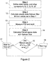
- Figure 1 shows schematically the process performed by the processor 1.
- the process may be considered as effectively comprising a recursive loop.
- the loop will now be described taking the start (somewhat arbitrarily) of the loop as being a step (represented by box 5) of predicting the state of the system, at an instant T in time in the future in view of data (represented by arrow 10) concerning the state of the system, and the estimated fuel flow rate, at a time T - ⁇ T before that instant in time, the state being defined by the estimated FQI, the estimated fuel leak amount and the estimated fuel leak rate.
- this prediction of the state of the system at time T is corrected, by means of a calculation using a Kalman gain matrix, in view of a measurement of the FQI (represented by box 3) at that time T.
- This correction procedure (represented by box 7) effectively uses a combination (represented by symbol 8) of the up-to-date measure at time T of the FQI (represented by box 3) and the predicted state of the system calculated in the previous step 5.
- the rate of flow of fuel from the fuel tank at that same given time is measured (input 2) and combined (symbol 9) with the corrected state of the system to provide the data (represented by arrow 10) concerning the state of the system at time T so that the step 5 of predicting the state of the system at a time T + ⁇ T in the future may be performed, thus repeating the loop.
- the data (arrow 10) provided, concerning the corrected state of the system at a given time includes data (represented by arrows 6a and 6b, respectively) of an estimated fuel leak amount and an estimated fuel leak rate.
- the estimated fuel leak data 6a, 6b are fed to a comparator 15 which ascertains whether the estimated fuel leak amount and/or rate are high enough to warrant the deemed detection of a fuel leak. If a leak is deemed detected a suitable output 4 is made.
- the fuel leak amount is added to the integrated fuel flow rate to give the modelled output (FQI).
- FQI modelled output
- This state-space system is used to form a state observer (or estimator) that provides estimates of the required leak information.
- a Kalman filter is used to provide an improved estimate of the state.
- the Kalman filter provides an improved estimate x ⁇ ( k / k ) of the state, x ( k ), given the output measurement, z ( k ) (i.e. the FQI input 3), and input measurement u ( k ) (i.e. the fuel flow rate input 2).
- the nomenclature k / k refers to the estimate at sample time k , given information up to sample time k .
- the sample period ⁇ T is chosen to be 15 seconds.
- the steady-state Kalman gain matrix M is calculated by using the Matlab function dlqe (A, G, C, Q, R).
- the first and second steps 11, 12 could actually be performed in advance and in isolation from the aircraft by using an appropriate mathematical model of the fuel system of the aircraft.
- the values of the constants and a nominal initial estimate of the system state could for example be pre-programmed as pre-set constants in the processor 1 during installation or programming of the processor 1 in the aircraft.
- the inputs 2, 3 representative of the measurements of the flow rate du/dt and the FQI measurement are sampled by the processor at a time T.
- the filtered estimated state quantity x ⁇ at time T is then calculated in a fourth step 14 by means of equation (8) from the estimated state quantity x ⁇ at time T- ⁇ T (in this initial calculation by using x ⁇ 0 ) and the measured flow rate ( u 0 ) at time T- ⁇ T and the measured FQI at time T.
- the state quantity x ⁇ ( k / k ) (at sample time k , where k T/ ⁇ T), thus calculated, contains a Kalman-filtered leak rate estimate, v ⁇ ( k / k ), and leak amount ⁇ ( k / k ).
- the processor 1 causes the warning device 4 to be activated (box 16).
- the system then repeats the steps from the third step 13 onwards in respect of a new sample time equal to T+ ⁇ T, thus effectively waiting (box 17) for a time ⁇ T before taking further measurements. The method is repeated until the monitoring system is deactivitated.
- the Kalman filter thus realizes a much more compact implementation of two leak detection methods (the integral method and a differential method), thereby reducing past measurement and state storage and furthermore achieving improved noise rejection properties.
- fuel may be depleted by means of usage of fuel by auxiliary power units, fuel flow to surge tanks (but not including flow of fuel from the surge tanks overboard, because such loss of fuel is in the present context classified as a leak), fuel being dispensed during air-to-air refuelling, intentional jettison of fuel (for example in an emergency), defuelling (for example, when the aircraft is grounded), fuel lost (as being unusable) within the fuel flow system as a result of a fuel transfer problem. Sensors are provided in order to account for all of the above means of fuel depletion when present.
- account must be taken of input of fuel into the tanks, for example, by means of refuelling, either on the ground or during air-to-air refuelling, or by means of a surge tank scavenge.
- the method may be improved by providing extra means for facilitating detection of leaks downstream of a flow rate sensor.
- the Kalman filtering method could be modified to be adaptive.
Landscapes
- Physics & Mathematics (AREA)
- Engineering & Computer Science (AREA)
- Power Engineering (AREA)
- Fluid Mechanics (AREA)
- General Physics & Mathematics (AREA)
- Electromagnetism (AREA)
- Thermal Sciences (AREA)
- Examining Or Testing Airtightness (AREA)
Claims (18)
- Procédé de détection d'une fuite de carburant à partir d'un réservoir de carburant (3) d'un aéronef, le procédé comprenant les étapes ci-dessous consistant à, ou dans lesquelles :(i) recevoir, au niveau d'un circuit (1), des signaux représentatifs de mesures physiques, réalisées à une pluralité d'instants successifs, de la quantité de carburant dans le réservoir de carburant (3), et du débit de carburant s'écoulant à partir du réservoir de carburant (2), les mesures étant chacune sujettes au bruit ;(ii) le circuit (1) définit, dans un espace d'états, un état de système d'écoulement de carburant, l'état du système étant défini par un ensemble de variables incluant au moins une variable connexe à une quantité représentée par les signaux reçus à l'étape (i) et une variable connexe à une fuite de carburant depuis la source de carburant ;(iii) le circuit (1) vérifie un nouvel état du système relativement à un état précédemment vérifié du système et une pluralité des mesures représentées par les signaux reçus à l'étape (i) ;(iv) le circuit (1) identifie, à partir du nouvel état du système, la présence éventuelle d'une fuite de carburant ;et, le cas échéant,(v) occasionner la mise en oeuvre d'une indication (4) d'une fuite de carburant suspectée.
- Procédé selon la revendication 1, dans lequel l'étape (iv) comprend l'étape consistant à vérifier une quantité de fuite de carburant à partir d'une ou plusieurs valeurs de l'état du système.
- Procédé selon la revendication 2, incluant une étape dans laquelle le circuit (1) considère la présence d'une fuite dans le cas où la quantité de fuite de carburant est supérieure à un seuil prédéfini.
- Procédé selon l'une quelconque des revendications précédentes, dans lequel l'étape (iv) comprend l'étape consistant à vérifier un débit de fuite de carburant à partir d'une ou plusieurs valeurs de l'état du système.
- Procédé selon la revendication 4, comprenant une étape dans laquelle le circuit (1) considère la présence d'une fuite dans le cas où le débit de fuite de carburant est supérieur à un seuil prédéfini.
- Procédé selon l'une quelconque des revendications précédentes, dans lequel l'étape de vérification du nouvel état du système ne prend en compte qu'un seul état vérifié précédent du système.
- Procédé selon l'une quelconque des revendications précédentes, dans lequel, au cours de l'étape (iii), la pluralité des mesures prises en compte par le circuit (1) lors de la vérification du nouvel état du système est représentative d'une pluralité de quantités différentes, et dans lequel, relativement à la totalité des différentes quantités respectives prises en compte lors de la vérification du nouvel état du système, l'instant de chaque mesure physique est identique relativement à une quantité unique mesurée.
- Procédé selon l'une quelconque des revendications précédentes, dans lequel au moins deux des mesures prises en compte lors de la vérification du nouvel état du système sont dérivées de mesures physiques de différentes quantités effectuées à différents instants.
- Procédé selon l'une quelconque des revendications précédentes, dans lequel l'une des mesures prises en compte lors de la vérification du nouvel état du système est dérivée d'une mesure physique effectuée sensiblement au même instant que l'instant du système auquel se rapporte le nouvel état.
- Procédé selon l'une quelconque des revendications précédentes, dans lequel l'étape consistant à vérifier le nouvel état du système inclut la prise en compte d'un unique état vérifié précédent du système, d'une unique mesure physique précédente du débit de carburant utilisé par l'aéronef et d'une unique mesure physique en cours de la quantité de carburant dans le réservoir de carburant.
- Procédé selon l'une quelconque des revendications précédentes, dans lequel les variables définissant l'état du système incluent une mesure d'une quantité de carburant, un débit de fuite de carburant et une quantité de fuite de carburant.
- Procédé selon l'une quelconque des revendications précédentes, dans lequel l'étape consistant à vérifier le nouvel état du système est mise en oeuvre sous la forme d'un procédé d'estimation d'état récurrent.
- Procédé selon l'une quelconque des revendications précédentes, dans lequel l'étape consistant à vérifier le nouvel état du système est réalisée au moyen d'un algorithme de filtre de Kalman.
- Procédé selon l'une quelconque des revendications précédentes, incluant une étape consistant à vérifier le débit d'écoulement probable de la fuite et la quantité probable du carburant ayant fui.
- Circuit agencé de manière à mettre en oeuvre le procédé selon l'une quelconque des revendications précédentes.
- Circuit selon la revendication 15, agencé de manière à recevoir des entrées représentatives de la quantité de carburant dans le réservoir de carburant d'un aéronef, et du débit de carburant utilisé par l'aéronef, et également agencé de manière à fournir une sortie indiquant l'existence éventuelle d'une fuite de carburant.
- Circuit selon la revendication 15 ou 16, dans lequel le circuit (1) comprend un processeur convenablement programmé.
- Produit logiciel portant un logiciel permettant à un processeur de mettre en oeuvre le procédé selon l'une quelconque des revendications 1 à 14.
Applications Claiming Priority (2)
| Application Number | Priority Date | Filing Date | Title |
|---|---|---|---|
| GBGB0421124.9A GB0421124D0 (en) | 2004-09-22 | 2004-09-22 | Fuel leak estimator |
| PCT/GB2005/003628 WO2006032873A1 (fr) | 2004-09-22 | 2005-09-21 | Estimateur de fuite de carburant |
Publications (2)
| Publication Number | Publication Date |
|---|---|
| EP1792158A1 EP1792158A1 (fr) | 2007-06-06 |
| EP1792158B1 true EP1792158B1 (fr) | 2017-04-12 |
Family
ID=33397098
Family Applications (1)
| Application Number | Title | Priority Date | Filing Date |
|---|---|---|---|
| EP05784187.6A Active EP1792158B1 (fr) | 2004-09-22 | 2005-09-21 | Estimateur de fuite de carburant |
Country Status (5)
| Country | Link |
|---|---|
| EP (1) | EP1792158B1 (fr) |
| BR (1) | BRPI0515570A (fr) |
| CA (1) | CA2580408C (fr) |
| GB (1) | GB0421124D0 (fr) |
| WO (1) | WO2006032873A1 (fr) |
Families Citing this family (7)
| Publication number | Priority date | Publication date | Assignee | Title |
|---|---|---|---|---|
| US7739004B2 (en) | 2006-11-29 | 2010-06-15 | The Boeing Company | Automatic engine fuel flow monitoring and alerting fuel leak detection method |
| CN111279174B (zh) | 2017-10-23 | 2022-07-01 | 庞巴迪公司 | 用于检测飞机中的燃料泄漏的系统和方法 |
| US11518671B2 (en) | 2020-06-30 | 2022-12-06 | Wayne Fueling Systems Llc | Real-time determination of meter drift via loss qualification and quantification |
| US11852563B2 (en) * | 2020-06-30 | 2023-12-26 | Wayne Fueling Systems Llc | Fuel leak determination via predictive modeling |
| US11912561B2 (en) | 2020-12-23 | 2024-02-27 | Wayne Fueling Systems Llc | Preventive maintenance of fuel dispensers through inventory reconciliation and identification of meter drift |
| CN114634007B (zh) * | 2022-02-11 | 2024-03-22 | 国能黄骅港务有限责任公司 | 翻车机给料系统及其低料位检测方法、装置 |
| US20230399986A1 (en) * | 2022-06-09 | 2023-12-14 | General Electric Company | Monitoring systems for hydrogen fueled aircraft |
Family Cites Families (3)
| Publication number | Priority date | Publication date | Assignee | Title |
|---|---|---|---|---|
| US5461903A (en) * | 1994-03-03 | 1995-10-31 | Fluid Power Industries, Inc. | Apparatus and method for detecting leak in hydraulic system |
| JP4571317B2 (ja) * | 1999-06-01 | 2010-10-27 | マサチューセッツ インスティテュート オブ テクノロジー | 無加圧帯式連続血圧監視装置 |
| US6502042B1 (en) * | 2000-10-26 | 2002-12-31 | Bfgoodrich Aerospace Fuel And Utility Systems | Fault tolerant liquid measurement system using multiple-model state estimators |
-
2004
- 2004-09-22 GB GBGB0421124.9A patent/GB0421124D0/en not_active Ceased
-
2005
- 2005-09-21 WO PCT/GB2005/003628 patent/WO2006032873A1/fr active Application Filing
- 2005-09-21 BR BRPI0515570-3A patent/BRPI0515570A/pt not_active IP Right Cessation
- 2005-09-21 EP EP05784187.6A patent/EP1792158B1/fr active Active
- 2005-09-21 CA CA2580408A patent/CA2580408C/fr not_active Expired - Fee Related
Non-Patent Citations (1)
| Title |
|---|
| None * |
Also Published As
| Publication number | Publication date |
|---|---|
| CA2580408A1 (fr) | 2006-03-30 |
| GB0421124D0 (en) | 2004-10-27 |
| EP1792158A1 (fr) | 2007-06-06 |
| CA2580408C (fr) | 2013-07-30 |
| WO2006032873A1 (fr) | 2006-03-30 |
| BRPI0515570A (pt) | 2008-07-29 |
Similar Documents
| Publication | Publication Date | Title |
|---|---|---|
| US7603242B2 (en) | Fuel leak estimator | |
| EP1792158B1 (fr) | Estimateur de fuite de carburant | |
| US9128109B1 (en) | Method and system for detecting errors in indicated air speed | |
| CN109524139B (zh) | 一种基于设备工况变化的实时设备性能监测方法 | |
| US8103462B2 (en) | Oil consumption monitoring for aircraft engine | |
| US8401760B2 (en) | Gas turbine engine oil consumption monitoring system and method | |
| US8417410B2 (en) | Operations support systems and methods with power management | |
| US8321118B2 (en) | Operations support systems and methods with power assurance | |
| EP3135911B1 (fr) | Surveillance de pompe médicale | |
| US8744651B2 (en) | Method of determining a maneuver performed by an aircraft | |
| US7739004B2 (en) | Automatic engine fuel flow monitoring and alerting fuel leak detection method | |
| EP1963184B1 (fr) | Systeme de reservoirs de carburant auxiliaires d aeronef et procede associe | |
| US10648605B2 (en) | Water hammer prevention system using operation state analysis algorithm | |
| EP2207072A2 (fr) | Systèmes de support d'opérations et procédés avec diagnostic de moteur | |
| EP0545450B1 (fr) | Détection statistique de fuites de liquide d'une canalisation | |
| US6502018B1 (en) | Method for diagnosis of equipment | |
| US7801695B2 (en) | Operations support systems and methods with model-based torque estimates | |
| US20120325348A1 (en) | System and method for fuel system health monitoring | |
| CN110582626A (zh) | 用由磨损因子校正的异常检测来监视涡轮机的系统和方法 | |
| CN111391660B (zh) | 检测储气瓶的压力的方法及装置、发动机 | |
| CN115563868A (zh) | 一种航空交流发电机油路系统故障诊断方法及装置 | |
| CN114148533A (zh) | 一种飞机液体渗漏实时监控系统和方法 | |
| US11280358B2 (en) | Method for monitoring the condition of the hydraulic system | |
| KR100569078B1 (ko) | 흡기온 센서 고장 판정장치 및 방법 | |
| CN117043452A (zh) | 监测喷气发动机中的防泄漏阀 |
Legal Events
| Date | Code | Title | Description |
|---|---|---|---|
| PUAI | Public reference made under article 153(3) epc to a published international application that has entered the european phase |
Free format text: ORIGINAL CODE: 0009012 |
|
| 17P | Request for examination filed |
Effective date: 20070330 |
|
| AK | Designated contracting states |
Kind code of ref document: A1 Designated state(s): AT BE BG CH CY CZ DE DK EE ES FI FR GB GR HU IE IS IT LI LT LU LV MC NL PL PT RO SE SI SK TR |
|
| 17Q | First examination report despatched |
Effective date: 20070731 |
|
| DAX | Request for extension of the european patent (deleted) | ||
| RAP1 | Party data changed (applicant data changed or rights of an application transferred) |
Owner name: AIRBUS OPERATIONS LIMITED |
|
| GRAP | Despatch of communication of intention to grant a patent |
Free format text: ORIGINAL CODE: EPIDOSNIGR1 |
|
| INTG | Intention to grant announced |
Effective date: 20160930 |
|
| GRAS | Grant fee paid |
Free format text: ORIGINAL CODE: EPIDOSNIGR3 |
|
| STAA | Information on the status of an ep patent application or granted ep patent |
Free format text: STATUS: GRANT OF PATENT IS INTENDED |
|
| GRAJ | Information related to disapproval of communication of intention to grant by the applicant or resumption of examination proceedings by the epo deleted |
Free format text: ORIGINAL CODE: EPIDOSDIGR1 |
|
| GRAL | Information related to payment of fee for publishing/printing deleted |
Free format text: ORIGINAL CODE: EPIDOSDIGR3 |
|
| STAA | Information on the status of an ep patent application or granted ep patent |
Free format text: STATUS: EXAMINATION IS IN PROGRESS |
|
| GRAR | Information related to intention to grant a patent recorded |
Free format text: ORIGINAL CODE: EPIDOSNIGR71 |
|
| STAA | Information on the status of an ep patent application or granted ep patent |
Free format text: STATUS: GRANT OF PATENT IS INTENDED |
|
| GRAA | (expected) grant |
Free format text: ORIGINAL CODE: 0009210 |
|
| STAA | Information on the status of an ep patent application or granted ep patent |
Free format text: STATUS: THE PATENT HAS BEEN GRANTED |
|
| INTC | Intention to grant announced (deleted) | ||
| AK | Designated contracting states |
Kind code of ref document: B1 Designated state(s): AT BE BG CH CY CZ DE DK EE ES FI FR GB GR HU IE IS IT LI LT LU LV MC NL PL PT RO SE SI SK TR |
|
| INTG | Intention to grant announced |
Effective date: 20170307 |
|
| REG | Reference to a national code |
Ref country code: GB Ref legal event code: FG4D |
|
| REG | Reference to a national code |
Ref country code: CH Ref legal event code: EP |
|
| REG | Reference to a national code |
Ref country code: IE Ref legal event code: FG4D |
|
| REG | Reference to a national code |
Ref country code: AT Ref legal event code: REF Ref document number: 884393 Country of ref document: AT Kind code of ref document: T Effective date: 20170515 |
|
| REG | Reference to a national code |
Ref country code: DE Ref legal event code: R096 Ref document number: 602005051734 Country of ref document: DE |
|
| REG | Reference to a national code |
Ref country code: FR Ref legal event code: PLFP Year of fee payment: 13 |
|
| REG | Reference to a national code |
Ref country code: NL Ref legal event code: MP Effective date: 20170412 |
|
| REG | Reference to a national code |
Ref country code: LT Ref legal event code: MG4D |
|
| REG | Reference to a national code |
Ref country code: AT Ref legal event code: MK05 Ref document number: 884393 Country of ref document: AT Kind code of ref document: T Effective date: 20170412 |
|
| PG25 | Lapsed in a contracting state [announced via postgrant information from national office to epo] |
Ref country code: NL Free format text: LAPSE BECAUSE OF FAILURE TO SUBMIT A TRANSLATION OF THE DESCRIPTION OR TO PAY THE FEE WITHIN THE PRESCRIBED TIME-LIMIT Effective date: 20170412 |
|
| PG25 | Lapsed in a contracting state [announced via postgrant information from national office to epo] |
Ref country code: ES Free format text: LAPSE BECAUSE OF FAILURE TO SUBMIT A TRANSLATION OF THE DESCRIPTION OR TO PAY THE FEE WITHIN THE PRESCRIBED TIME-LIMIT Effective date: 20170412 Ref country code: FI Free format text: LAPSE BECAUSE OF FAILURE TO SUBMIT A TRANSLATION OF THE DESCRIPTION OR TO PAY THE FEE WITHIN THE PRESCRIBED TIME-LIMIT Effective date: 20170412 Ref country code: GR Free format text: LAPSE BECAUSE OF FAILURE TO SUBMIT A TRANSLATION OF THE DESCRIPTION OR TO PAY THE FEE WITHIN THE PRESCRIBED TIME-LIMIT Effective date: 20170713 Ref country code: AT Free format text: LAPSE BECAUSE OF FAILURE TO SUBMIT A TRANSLATION OF THE DESCRIPTION OR TO PAY THE FEE WITHIN THE PRESCRIBED TIME-LIMIT Effective date: 20170412 Ref country code: LT Free format text: LAPSE BECAUSE OF FAILURE TO SUBMIT A TRANSLATION OF THE DESCRIPTION OR TO PAY THE FEE WITHIN THE PRESCRIBED TIME-LIMIT Effective date: 20170412 |
|
| PG25 | Lapsed in a contracting state [announced via postgrant information from national office to epo] |
Ref country code: BG Free format text: LAPSE BECAUSE OF FAILURE TO SUBMIT A TRANSLATION OF THE DESCRIPTION OR TO PAY THE FEE WITHIN THE PRESCRIBED TIME-LIMIT Effective date: 20170712 Ref country code: LV Free format text: LAPSE BECAUSE OF FAILURE TO SUBMIT A TRANSLATION OF THE DESCRIPTION OR TO PAY THE FEE WITHIN THE PRESCRIBED TIME-LIMIT Effective date: 20170412 Ref country code: IS Free format text: LAPSE BECAUSE OF FAILURE TO SUBMIT A TRANSLATION OF THE DESCRIPTION OR TO PAY THE FEE WITHIN THE PRESCRIBED TIME-LIMIT Effective date: 20170812 Ref country code: PL Free format text: LAPSE BECAUSE OF FAILURE TO SUBMIT A TRANSLATION OF THE DESCRIPTION OR TO PAY THE FEE WITHIN THE PRESCRIBED TIME-LIMIT Effective date: 20170412 Ref country code: SE Free format text: LAPSE BECAUSE OF FAILURE TO SUBMIT A TRANSLATION OF THE DESCRIPTION OR TO PAY THE FEE WITHIN THE PRESCRIBED TIME-LIMIT Effective date: 20170412 |
|
| REG | Reference to a national code |
Ref country code: DE Ref legal event code: R097 Ref document number: 602005051734 Country of ref document: DE |
|
| PG25 | Lapsed in a contracting state [announced via postgrant information from national office to epo] |
Ref country code: DK Free format text: LAPSE BECAUSE OF FAILURE TO SUBMIT A TRANSLATION OF THE DESCRIPTION OR TO PAY THE FEE WITHIN THE PRESCRIBED TIME-LIMIT Effective date: 20170412 Ref country code: RO Free format text: LAPSE BECAUSE OF FAILURE TO SUBMIT A TRANSLATION OF THE DESCRIPTION OR TO PAY THE FEE WITHIN THE PRESCRIBED TIME-LIMIT Effective date: 20170412 Ref country code: EE Free format text: LAPSE BECAUSE OF FAILURE TO SUBMIT A TRANSLATION OF THE DESCRIPTION OR TO PAY THE FEE WITHIN THE PRESCRIBED TIME-LIMIT Effective date: 20170412 Ref country code: CZ Free format text: LAPSE BECAUSE OF FAILURE TO SUBMIT A TRANSLATION OF THE DESCRIPTION OR TO PAY THE FEE WITHIN THE PRESCRIBED TIME-LIMIT Effective date: 20170412 Ref country code: SK Free format text: LAPSE BECAUSE OF FAILURE TO SUBMIT A TRANSLATION OF THE DESCRIPTION OR TO PAY THE FEE WITHIN THE PRESCRIBED TIME-LIMIT Effective date: 20170412 |
|
| PLBE | No opposition filed within time limit |
Free format text: ORIGINAL CODE: 0009261 |
|
| STAA | Information on the status of an ep patent application or granted ep patent |
Free format text: STATUS: NO OPPOSITION FILED WITHIN TIME LIMIT |
|
| PG25 | Lapsed in a contracting state [announced via postgrant information from national office to epo] |
Ref country code: IT Free format text: LAPSE BECAUSE OF FAILURE TO SUBMIT A TRANSLATION OF THE DESCRIPTION OR TO PAY THE FEE WITHIN THE PRESCRIBED TIME-LIMIT Effective date: 20170412 |
|
| 26N | No opposition filed |
Effective date: 20180115 |
|
| REG | Reference to a national code |
Ref country code: CH Ref legal event code: PL |
|
| PG25 | Lapsed in a contracting state [announced via postgrant information from national office to epo] |
Ref country code: SI Free format text: LAPSE BECAUSE OF FAILURE TO SUBMIT A TRANSLATION OF THE DESCRIPTION OR TO PAY THE FEE WITHIN THE PRESCRIBED TIME-LIMIT Effective date: 20170412 Ref country code: MC Free format text: LAPSE BECAUSE OF FAILURE TO SUBMIT A TRANSLATION OF THE DESCRIPTION OR TO PAY THE FEE WITHIN THE PRESCRIBED TIME-LIMIT Effective date: 20170412 |
|
| REG | Reference to a national code |
Ref country code: IE Ref legal event code: MM4A |
|
| REG | Reference to a national code |
Ref country code: BE Ref legal event code: MM Effective date: 20170930 |
|
| PG25 | Lapsed in a contracting state [announced via postgrant information from national office to epo] |
Ref country code: LU Free format text: LAPSE BECAUSE OF NON-PAYMENT OF DUE FEES Effective date: 20170921 |
|
| PG25 | Lapsed in a contracting state [announced via postgrant information from national office to epo] |
Ref country code: LI Free format text: LAPSE BECAUSE OF NON-PAYMENT OF DUE FEES Effective date: 20170930 Ref country code: IE Free format text: LAPSE BECAUSE OF NON-PAYMENT OF DUE FEES Effective date: 20170921 Ref country code: CH Free format text: LAPSE BECAUSE OF NON-PAYMENT OF DUE FEES Effective date: 20170930 |
|
| PG25 | Lapsed in a contracting state [announced via postgrant information from national office to epo] |
Ref country code: BE Free format text: LAPSE BECAUSE OF NON-PAYMENT OF DUE FEES Effective date: 20170930 |
|
| REG | Reference to a national code |
Ref country code: FR Ref legal event code: PLFP Year of fee payment: 14 |
|
| PG25 | Lapsed in a contracting state [announced via postgrant information from national office to epo] |
Ref country code: HU Free format text: LAPSE BECAUSE OF FAILURE TO SUBMIT A TRANSLATION OF THE DESCRIPTION OR TO PAY THE FEE WITHIN THE PRESCRIBED TIME-LIMIT; INVALID AB INITIO Effective date: 20050921 |
|
| PG25 | Lapsed in a contracting state [announced via postgrant information from national office to epo] |
Ref country code: CY Free format text: LAPSE BECAUSE OF NON-PAYMENT OF DUE FEES Effective date: 20170412 |
|
| PGFP | Annual fee paid to national office [announced via postgrant information from national office to epo] |
Ref country code: DE Payment date: 20190918 Year of fee payment: 15 Ref country code: FR Payment date: 20190926 Year of fee payment: 15 |
|
| PG25 | Lapsed in a contracting state [announced via postgrant information from national office to epo] |
Ref country code: TR Free format text: LAPSE BECAUSE OF FAILURE TO SUBMIT A TRANSLATION OF THE DESCRIPTION OR TO PAY THE FEE WITHIN THE PRESCRIBED TIME-LIMIT Effective date: 20170412 |
|
| PG25 | Lapsed in a contracting state [announced via postgrant information from national office to epo] |
Ref country code: PT Free format text: LAPSE BECAUSE OF FAILURE TO SUBMIT A TRANSLATION OF THE DESCRIPTION OR TO PAY THE FEE WITHIN THE PRESCRIBED TIME-LIMIT Effective date: 20170412 |
|
| REG | Reference to a national code |
Ref country code: DE Ref legal event code: R119 Ref document number: 602005051734 Country of ref document: DE |
|
| PG25 | Lapsed in a contracting state [announced via postgrant information from national office to epo] |
Ref country code: DE Free format text: LAPSE BECAUSE OF NON-PAYMENT OF DUE FEES Effective date: 20210401 Ref country code: FR Free format text: LAPSE BECAUSE OF NON-PAYMENT OF DUE FEES Effective date: 20200930 |
|
| PGFP | Annual fee paid to national office [announced via postgrant information from national office to epo] |
Ref country code: GB Payment date: 20230920 Year of fee payment: 19 |