EP1791150B1 - Low current electric motor protector - Google Patents
Low current electric motor protector Download PDFInfo
- Publication number
- EP1791150B1 EP1791150B1 EP07001741A EP07001741A EP1791150B1 EP 1791150 B1 EP1791150 B1 EP 1791150B1 EP 07001741 A EP07001741 A EP 07001741A EP 07001741 A EP07001741 A EP 07001741A EP 1791150 B1 EP1791150 B1 EP 1791150B1
- Authority
- EP
- European Patent Office
- Prior art keywords
- lid
- motor protector
- housing
- received
- protector according
- Prior art date
- Legal status (The legal status is an assumption and is not a legal conclusion. Google has not performed a legal analysis and makes no representation as to the accuracy of the status listed.)
- Expired - Lifetime
Links
- 230000001012 protector Effects 0.000 title claims description 37
- 239000000919 ceramic Substances 0.000 description 11
- 239000000758 substrate Substances 0.000 description 9
- 239000000463 material Substances 0.000 description 5
- 238000003466 welding Methods 0.000 description 4
- 230000035945 sensitivity Effects 0.000 description 3
- 238000000926 separation method Methods 0.000 description 3
- 230000008878 coupling Effects 0.000 description 2
- 238000010168 coupling process Methods 0.000 description 2
- 238000005859 coupling reaction Methods 0.000 description 2
- 230000003247 decreasing effect Effects 0.000 description 2
- 238000012986 modification Methods 0.000 description 2
- 230000004048 modification Effects 0.000 description 2
- 230000000153 supplemental effect Effects 0.000 description 2
- 241000237858 Gastropoda Species 0.000 description 1
- BQCADISMDOOEFD-UHFFFAOYSA-N Silver Chemical compound [Ag] BQCADISMDOOEFD-UHFFFAOYSA-N 0.000 description 1
- 238000004891 communication Methods 0.000 description 1
- 239000004020 conductor Substances 0.000 description 1
- 238000001816 cooling Methods 0.000 description 1
- 239000012777 electrically insulating material Substances 0.000 description 1
- 239000011521 glass Substances 0.000 description 1
- 238000002955 isolation Methods 0.000 description 1
- 229910052751 metal Inorganic materials 0.000 description 1
- 239000002184 metal Substances 0.000 description 1
- 238000000034 method Methods 0.000 description 1
- 229910052709 silver Inorganic materials 0.000 description 1
- 239000004332 silver Substances 0.000 description 1
- 238000005476 soldering Methods 0.000 description 1
- 229910001220 stainless steel Inorganic materials 0.000 description 1
- 239000010935 stainless steel Substances 0.000 description 1
- 239000007858 starting material Substances 0.000 description 1
- 238000009966 trimming Methods 0.000 description 1
Images


Classifications
-
- H—ELECTRICITY
- H01—ELECTRIC ELEMENTS
- H01H—ELECTRIC SWITCHES; RELAYS; SELECTORS; EMERGENCY PROTECTIVE DEVICES
- H01H37/00—Thermally-actuated switches
- H01H37/02—Details
-
- H—ELECTRICITY
- H01—ELECTRIC ELEMENTS
- H01H—ELECTRIC SWITCHES; RELAYS; SELECTORS; EMERGENCY PROTECTIVE DEVICES
- H01H61/00—Electrothermal relays
- H01H61/02—Electrothermal relays wherein the thermally-sensitive member is heated indirectly, e.g. resistively, inductively
-
- H—ELECTRICITY
- H01—ELECTRIC ELEMENTS
- H01H—ELECTRIC SWITCHES; RELAYS; SELECTORS; EMERGENCY PROTECTIVE DEVICES
- H01H37/00—Thermally-actuated switches
- H01H37/02—Details
- H01H37/32—Thermally-sensitive members
- H01H37/52—Thermally-sensitive members actuated due to deflection of bimetallic element
- H01H37/54—Thermally-sensitive members actuated due to deflection of bimetallic element wherein the bimetallic element is inherently snap acting
- H01H37/5418—Thermally-sensitive members actuated due to deflection of bimetallic element wherein the bimetallic element is inherently snap acting using cantilevered bimetallic snap elements
-
- H—ELECTRICITY
- H01—ELECTRIC ELEMENTS
- H01H—ELECTRIC SWITCHES; RELAYS; SELECTORS; EMERGENCY PROTECTIVE DEVICES
- H01H37/00—Thermally-actuated switches
- H01H37/02—Details
- H01H37/32—Thermally-sensitive members
- H01H37/52—Thermally-sensitive members actuated due to deflection of bimetallic element
- H01H37/54—Thermally-sensitive members actuated due to deflection of bimetallic element wherein the bimetallic element is inherently snap acting
- H01H37/5427—Thermally-sensitive members actuated due to deflection of bimetallic element wherein the bimetallic element is inherently snap acting encapsulated in sealed miniaturised housing
Definitions
- This invention relates generally to motor protectors and more particularly to low current protectors for electrical devices such as compressors, transformers and small motors against overload and locked rotor.
- U.S. Patent No. 4,476,452 comprises a metallic housing having an open end with a flange formed around the open end and a gasket and lid received on and clamped to the housing.
- a heat responsive electrical switch is disposed in the housing and is adapted to electrically connect and disconnect a current path through the housing and lid upon the occurrence of selected thermal conditions.
- the lid comprises two discrete, spaced apart portions, one portion having an elongated part extended therefrom to serve as a terminal and the other portion mounting a portion of the switch.
- a coil heater is electrically and mechanically connected between the spaced apart portions of the lid providing a protector particularly useful for fractional horsepower motors.
- motor protectors made according to the above referenced patent are suitable for low current applications, there is a need to provide a low cost protector useful for low current applications having even more current sensitivity yet one which is mechanically robust and one which has increased reset times required for certain applications, such as protecting compressor motors.
- Another object of the invention is the provision of a low current motor protector which has improved current sensitivity, yet is mechanically robust.regarding handling and vibration.
- Yet another object of the invention is the provision of a motor protector of the low current type which can be easily and accurately adapted for use with different electrical devices, such as compressors, transformers and small motors.
- Yet another object of the invention is the provision of a low current motor protector which is particularly conducive to low cost assembly techniques.
- Still another object of the invention is the provision of a low current motor protector which has an end of life, open circuit condition.
- the invention comprises a coil heater has one end thereof attached to a first of a two part lid clampingly received on the housing through an electrically insulative gasket and a second end thereof attached to the second of the two part lid also clampingly received on the housing through the gasket.
- the two part lid has a dome configuration formed in a portion of the otherwise generally planar lid parts along with laterally extending tabs adapted to be bent over to clampingly engage the laterally extending flange portions of the housing through the gasket.
- the coil heater is received in the recess of the dome configuration in heat transfer relation with the thermostatic switch and the two lid parts are spaced longitudinally from each other sufficiently to maintain electrical separation from each other.
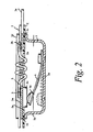
- a prior art low current motor protector comprises an oblong metallic housing 1 having a bottom wall 1a, sidewall 1b and a laterally, outwardly extending flange 1c at a free end of the sidewall.
- a gasket 2 of electrically insulating material is received on flange 1 c and a lid 3 formed of spaced apart parts 3a, 3b are received on gasket 2.
- An extended portion 1d of flange 1c on opposed sides of the housing are bent over to clamp the lid parts 3a, 3b, through the gasket.
- Gasket 2 is formed with a window 2a aligned with a switch chamber defined by the sidewall 1 b of the housing and a thermostatic switch comprising a snap-acting bimetallic member 4 has one end fixedly mounted on the bottom wall 1a of the housing and a free distal end mounting a movable electrical contact 4a movable into and out of engagement with stationary contact 3c welded to lid part 3a.
- a supplemental coil heater 5 has one end welded to lid part 3b and an opposite end welded to lid part 3a. Lid part 3b is formed with a terminal portion 3e and housing 1 is formed with a terminal 1e.
- Movable contact 4a is normally in electrical engagement with stationary electrical contact 3c thereby forming a current path between the terminals through bimetal 4 and coil heater 5; however, upon being heated to a selected temperature, for example, due to an overload current, disc 4 will snap to its dashed line configuration to open the circuit.
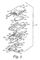
- a motor protector 10 (not claimed in the present patent) comprises a metallic oblong housing 12 having a bottom wall 12a, sidewalls 12b extending away from the bottom wall and having a flange 12c extending laterally and outwardly from the free end of the sidewall.
- Switch 14 is received in a switch chamber 12d defined by sidewalls 12b.
- Switch 14 comprises a bimetallic, snap acting disc 14a, known in the art, having one end 14b cantilever attached to the bottom wall 12a of the housing, preferably at an inwardly extending platform 12e, as by welding thereto using welding slug 14c.
- a movable electrical contact 14d is mounted at the free end 14e of the disc on the side thereof facing away from the bottom wall of the housing.
- An electrically insulating gasket 16 generally in a shape of a window frame 16a, is received on and covers flange 12c of the housing.
- the gasket has an extended portion 16b along two elongated opposite sides which are folded back toward the center of the window frame configuration into a generally V-shape in order to sandwich two opposed flange portions of the housing between layers 16a and 16b.
- an additional portion 16c extends from extended portion 16b for placement along the sidewalls 12b of the housing to ensure electrical isolation between lid parts, to be discussed, and the housing.
- a lid 18 comprises first and second parts 18a, 18b, respectively.
- Each lid part has a flat support portion 18c, 18d, respectively, lying in a plane, for reception on the frame gasket portion 16a on flange 12c and opposed tabs 18e bent back toward the center of the lid part forming a generally a V configuration with the support portion.
- Tabs 18e on lid part 18b are formed with a cut-out on the curved portion of the bend of the tabs to define catch surfaces 18k lying in the plane of support portion 18d extending into the cut-out for a purpose to be described.
- Each lid part is formed with a heater seat in the form of a contact shelf 18f spaced from the plane in which the respective support portion 18c, 18d, lie on the side of the lid parts facing the switch chamber so that the shelves are disposed within the switch chamber 12d when the lids are placed on the housing.
- Respective side and back walls 18g, 18h are joined to the shelves to ensure a robust seat for maintaining a selected location of a heater element.
- Shelves 18f are aligned and face each other and are spaced from each other a selected amount to provide direct, close, radiational heat coupling of a heat element received on the shelves with snap acting thermostatic disc 14a.
- a heater element in the form of a ceramic substrate 20 has opposed first and second face surfaces 20a, 20b and first and second ends 20c, 20d, respectively.
- An electrical contact layer 20e of suitable material such as a silver containing material, preferably formed with external contact bumps, extends across each end 20c, 20d on first face surface 20a and an electrical resistive thick film layer 20f covered by a glass layer is disposed on the first face surface 20a extending between and in electrical connection with the contact layers.
- the contact layers of the ceramic substrate are adapted to be received on ledges 18f with the ceramic element closely fitting in the recessed seat and with the heater surface facing thermostatic disc 14a.
- a stationary electrical contact 21 is mounted preferably on a platform formed in support portion 18c of lid part 18a on the side of the lid part having shelf 18f.
- Movable contact 14d is adapted to move into and out of engagement with stationary contact 21 in dependence upon the dished configuration of the thermostatic disc 14a.
- a spring clip 22 is formed of suitable material such as stainless steel and generally has an elongated body portion to extend across the width of housing 12 with opposite end portions 22a bent back on themselves to form a generally V configuration with the body portion and a locking tab 22b is struck out from each bent over portion with the free end 22c of the tab extending away from the free end of each locking tab portion 22b.
- a force application portion in the form of a projection 22e extends away from the body portion of clip 22 on the same side of the clip that end portions 22a are bent to extend.
- One terminal 12f extends from housing 12 and another terminal 18m extends from lid part 18b.
- thermostatic switch 14 is mounted in switch chamber 12d, gasket 16 is slipped onto flange 12c followed by lid parts 18a, 18b with V-shaped tabs 18e slipped over gasket 16, including portion 16b.
- the lid parts are spaced from one another a selected distance sufficient to ensure electrical separation and with ledges 18f property spaced from each other to receive ceramic substrate 20 thereon with the contact surfaces 20e received on respective shelves 18f.
- Tabs 18e are then bent inwardly to clamp the lid parts in their selected positions.
- the ceramic substrate is then inserted and clip 22 is placed over lid portion 18b so that end portions 22a are received over tabs 18e and with struck out locking tab 22b received under respective catch surfaces 18k and with force application portion 22e placing a force on face 20b of ceramic substrate 20.
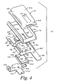
- Fig. 4 shows a modified motor protector 10' (again, not claimed in the present patent) in which catch surfaces 18k are formed in lid portion 18a' and clip 22' is formed with a leg portion 22f for positioning force application projection 22e' so that it will be aligned with the center of ceramic substrate 20 when clip 22' is attached to lid part 18a'.
- Leg 22f may be bent upwardly, as shown in the drawing, for example, along dashed line 18g, to provide a suitable bias to the ceramic substrate.
- Motor protector 10, 10' made in accordance with the preferred embodiments offer a number of advantages over the prior art.
- the cross section of the heater material is decreased to provide increased resistance making the protector more current sensitive but without loosing robustness.
- the ceramic substrate adds thermal mass to the heater element to increase the reset time of the thermostatic switch, a feature which is important for certain applications, for example, those with compressors which require an extended cool down time for a PTC starter.
- Placement of the heater in a recess formed in the switch chamber of the housing provides optimum thermal coupling with the thermostatic switch as well as providing a seat for the heater protected from accidental dislodgement during handling, vibration and the like.
- the thick film heater provides a fail safe end of life, i.e., burn out of the heater material or breaking of the ceramic substrate results in an open circuit.
- Use of the thick film heater also provides an advantage in that the heater film can be trimmed to provide accurate resistance values resulting in accurate time behavior. Further, laser trimming allows more flexibility in defining the nominal resistance value and can be used with the wider range of values than a corresponding coil heater and hence can be used in a wider range of applications.
- the use of the spring clip to maintain the ceramic heater in its seat ensures optimum electrical and mechanical connection while avoiding welding or soldering operations.
- Fig. 3 and 4 are not embodiments of the invention, but are useful for understanding the invention.
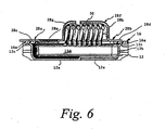
- a motor protector 100 comprising an oblong metal housing 12, as shown in the motor protector of figures 3 , 4 above.
- Housing 12 has bottom wall 12a, side walls 12b extending from the bottom wall, a flange 12c extending laterally outwardly from the free end of at least portions of the sidewalls along with a terminal 12f extending longitudinally from flange 12c at one end of the housing.
- thermostatic switch (not shown) of the type shown in Fig. 3 is received in a switch chamber 12d, the thermostatic disc member preferably mounted on platform 12e of bottom wall 12a.
- Electrically insulating gasket 16 is received on and covers flange 12c of the housing, again as in the motor protector of figures 3 and 4 above.
- a lid 28 of electrically conductive material comprises first and second parts 28a, 28b, respectively.
- Each lid part has a flat support portion 28c, 28d, respectively, lying in a plane for reception on the frame gasket portion 16a and flange 12c and opposed tabs 28e bent inward toward the center of the respective lid part forming a generally V configuration with the support portions, as in the previously described embodiments.
- a stationary contact platform 28m and a terminal 28n are formed on lid part 28a.
- a dome shaped configuration 28f is formed in the flat support portion of the lids which extends in a direction generally parallel to the longitudinal axis 2 of oblong housing 12. As shown, dome 28f has a first, relatively minor, longitudinal length portion 28g in first lid part 28a and a second, relatively major, longitudinal length portion 28h in second lid part 28b.
- lid parts 28a, 28b preferably have a wider flat support surface on one side of the longitudinal axis 2 of the lid to facilitate placement of weld projections 28j, 28k on respective lid parts while maximizing the available longitudinal space available for the helical configuration of the heater, to be discussed.
- the weld projections can be formed by local deformation of the flat support portions or by placement of weld slugs, as desired.
- the wall of dome configuration 28f is formed with a cut-out aligned with each weld projection to allow an end of a coil heater to pass through for attachment thereto.
- a helical or coil heater 30 has a first end 30a and a second end 30b attached to respective weld projections 28j, 28k, as by welding with the helical portion of the heater disposed within the concave recess formed by the dome configuration in direct thermal communication with the thermostatic switch received in housing 12.
- Lid parts 28a, 28b are clamped to housing 12 by means of tabs 28e with the lid parts spaced from one another along longitudinal axis 2 enough to provide suitable electrical separation between the two lid parts but otherwise close enough to effectively form an enclosure to retain heat generated by the coil heater for an extended period and thereby extend the off or reset time of the thermostatic switch.
- Dome configuration 28f also serves to protect the coil heater during handling and the like.
Landscapes
- Physics & Mathematics (AREA)
- Thermal Sciences (AREA)
- Thermally Actuated Switches (AREA)
- Control Of Electric Motors In General (AREA)
Applications Claiming Priority (3)
| Application Number | Priority Date | Filing Date | Title |
|---|---|---|---|
| US10/727,297 US6995647B2 (en) | 2003-12-03 | 2003-12-03 | Low current electric motor protector |
| US10/843,101 US7102481B2 (en) | 2003-12-03 | 2004-05-11 | Low current electric motor protector |
| EP04256918A EP1538652A3 (en) | 2003-12-03 | 2004-11-08 | Low current electric motor protector |
Related Parent Applications (2)
| Application Number | Title | Priority Date | Filing Date |
|---|---|---|---|
| EP04256918.6 Division | 2004-11-08 | ||
| EP04256918A Division EP1538652A3 (en) | 2003-12-03 | 2004-11-08 | Low current electric motor protector |
Publications (2)
| Publication Number | Publication Date |
|---|---|
| EP1791150A1 EP1791150A1 (en) | 2007-05-30 |
| EP1791150B1 true EP1791150B1 (en) | 2010-12-08 |
Family
ID=34468079
Family Applications (2)
| Application Number | Title | Priority Date | Filing Date |
|---|---|---|---|
| EP07001741A Expired - Lifetime EP1791150B1 (en) | 2003-12-03 | 2004-11-08 | Low current electric motor protector |
| EP04256918A Withdrawn EP1538652A3 (en) | 2003-12-03 | 2004-11-08 | Low current electric motor protector |
Family Applications After (1)
| Application Number | Title | Priority Date | Filing Date |
|---|---|---|---|
| EP04256918A Withdrawn EP1538652A3 (en) | 2003-12-03 | 2004-11-08 | Low current electric motor protector |
Country Status (6)
| Country | Link |
|---|---|
| US (1) | US7102481B2 (enExample) |
| EP (2) | EP1791150B1 (enExample) |
| JP (1) | JP4463088B2 (enExample) |
| KR (1) | KR100947519B1 (enExample) |
| CN (1) | CN100456591C (enExample) |
| BR (1) | BRPI0405304A (enExample) |
Families Citing this family (15)
| Publication number | Priority date | Publication date | Assignee | Title |
|---|---|---|---|---|
| US7326887B1 (en) * | 2006-12-13 | 2008-02-05 | Sensata Technologies, Inc. | Modified reset motor protector |
| WO2009128535A1 (ja) * | 2008-04-18 | 2009-10-22 | タイコ エレクトロニクス レイケム株式会社 | 回路保護デバイス |
| IT1392191B1 (it) * | 2008-12-12 | 2012-02-22 | Electrica Srl | Protettore termico per motori elettrici, in particolare per motori eletrici per compressori |
| EP2282320A1 (de) * | 2009-08-01 | 2011-02-09 | Limitor GmbH | Bimetall-Schnappscheibe |
| CN101895093B (zh) * | 2010-05-06 | 2012-07-25 | 舟山市定海区巨洋技术开发有限公司 | 船舶舾装数控切割机外力过载保护器 |
| WO2012037991A1 (de) * | 2010-09-24 | 2012-03-29 | Ellenberger & Poensgen Gmbh | Miniatur-schutzschalter |
| DE102011108660B3 (de) * | 2011-06-28 | 2012-11-22 | Thermik Gerätebau GmbH | Selbsthaltender temperaturabhängiger Schalter |
| CN103608886B (zh) * | 2011-06-28 | 2015-12-23 | 打矢恒温器株式会社 | 马达保护器 |
| US9048048B2 (en) * | 2012-08-16 | 2015-06-02 | Uchiya Thermostat Co., Ltd. | Thermal protector |
| CN105225893A (zh) * | 2015-10-08 | 2016-01-06 | 常州市家虹包装有限公司 | 防松型保护器 |
| TWI571035B (zh) * | 2015-10-20 | 2017-02-11 | 財團法人成大研究發展基金會 | 回授能量型保護器可靠性之測試電路系統 |
| CN107275134B (zh) * | 2017-07-14 | 2019-03-05 | 杭州星帅尔电器股份有限公司 | 微型热保护器的装配方法 |
| CN107248477B (zh) * | 2017-07-14 | 2019-03-05 | 杭州星帅尔电器股份有限公司 | 微型热保护器及其发热丝的安装方法 |
| CN107270862B (zh) * | 2017-07-14 | 2019-04-30 | 杭州星帅尔电器股份有限公司 | 微型热保护器中发热丝平整度的检测方法 |
| CN118321763B (zh) * | 2024-06-11 | 2024-08-16 | 江苏亿诚环保设备制造有限公司 | 一种数控切割机外力过载保护器 |
Family Cites Families (27)
| Publication number | Priority date | Publication date | Assignee | Title |
|---|---|---|---|---|
| US3095486A (en) * | 1960-07-14 | 1963-06-25 | Texas Instruments Inc | Miniaturized printed circuit electrical switching device |
| US3430177A (en) * | 1966-12-30 | 1969-02-25 | Texas Instruments Inc | Miniature thermostatic switch |
| US3622930A (en) * | 1969-10-16 | 1971-11-23 | Texas Instruments Inc | Motor protector apparatus and method |
| US3753195A (en) * | 1972-09-20 | 1973-08-14 | Gen Electric | Thermostatic switch |
| US4015229A (en) * | 1975-01-10 | 1977-03-29 | Texas Instruments Incorporated | Thermally responsive switch |
| US4086558A (en) * | 1976-02-09 | 1978-04-25 | Texas Instruments Incorporated | Motor protector and system |
| US4136323A (en) * | 1977-06-01 | 1979-01-23 | Entremont John R D | Miniature motor protector |
| US4224591A (en) * | 1978-12-04 | 1980-09-23 | Texas Instruments Incorporated | Motor protector with metal housing and with preformed external heater thereon |
| US4399423A (en) * | 1982-03-29 | 1983-08-16 | Texas Instruments Incorporated | Miniature electric circuit protector |
| US4476452A (en) * | 1982-09-27 | 1984-10-09 | Texas Instruments Incorporated | Motor protector |
| USD281240S (en) * | 1983-03-16 | 1985-11-05 | Portage Electric Products, Inc. | Housing for a thermostatic switch |
| US4490704A (en) * | 1983-09-14 | 1984-12-25 | Therm-O-Disc, Incorporated | Thermally responsive switching device |
| US4646195A (en) * | 1983-11-14 | 1987-02-24 | Texas Instruments Incorporated | Motor protector particularly suited for use with compressor motors |
| USD336072S (en) * | 1991-07-23 | 1993-06-01 | Portage Electric Product, Inc. | Housing for a thermostatic switch |
| US5206622A (en) * | 1992-04-10 | 1993-04-27 | Texas Instruments Incorporated | Protector device with improved bimetal contact assembly and method of making |
| DE4428226C1 (de) * | 1994-08-10 | 1995-10-12 | Thermik Geraetebau Gmbh | Temperaturwächter |
| US5808539A (en) * | 1996-10-10 | 1998-09-15 | Texas Instruments Incorporated | Temperature responsive snap acting control assembly, device using such assembly and method for making |
| EP0866482B1 (en) * | 1997-03-18 | 2000-07-26 | Texas Instruments Incorporated | Improved low cost thermostat apparatus and method for calibrating same |
| DE19727197C2 (de) * | 1997-06-26 | 1999-10-21 | Marcel Hofsaess | Temperaturabhängiger Schalter mit Kontaktbrücke |
| US5936510A (en) * | 1998-05-22 | 1999-08-10 | Portage Electric Products, Inc. | Sealed case hold open thermostat |
| US6020807A (en) * | 1999-02-23 | 2000-02-01 | Portage Electric Products, Inc. | Sealed case hold open thermostat |
| JP4545354B2 (ja) * | 2001-04-23 | 2010-09-15 | アスモ株式会社 | モータ及び封止構造 |
| US6756876B2 (en) * | 2001-09-24 | 2004-06-29 | Texas Instruments Incorporated | Circuit interrupter and method |
| CN2505974Y (zh) * | 2001-10-25 | 2002-08-14 | 邵志成 | 改良温度感应控制结构的器具插座 |
| US6744345B2 (en) * | 2002-05-06 | 2004-06-01 | Cooper Technologies | Mid-range circuit breaker |
| KR200296482Y1 (ko) * | 2002-08-27 | 2002-11-23 | 텍사스 인스트루먼트 코리아 주식회사 | 밀봉 구조의 과부하 보호기 |
| JP2005108585A (ja) * | 2003-09-30 | 2005-04-21 | Alps Electric Co Ltd | 熱応動スイッチ |
-
2004
- 2004-05-11 US US10/843,101 patent/US7102481B2/en not_active Expired - Lifetime
- 2004-11-08 EP EP07001741A patent/EP1791150B1/en not_active Expired - Lifetime
- 2004-11-08 EP EP04256918A patent/EP1538652A3/en not_active Withdrawn
- 2004-11-30 BR BR0405304-4A patent/BRPI0405304A/pt not_active Application Discontinuation
- 2004-12-02 JP JP2004349509A patent/JP4463088B2/ja not_active Expired - Fee Related
- 2004-12-03 KR KR1020040100787A patent/KR100947519B1/ko not_active Expired - Fee Related
- 2004-12-03 CN CNB2004100983451A patent/CN100456591C/zh not_active Expired - Fee Related
Also Published As
| Publication number | Publication date |
|---|---|
| KR100947519B1 (ko) | 2010-03-12 |
| KR20050053513A (ko) | 2005-06-08 |
| US20050122205A1 (en) | 2005-06-09 |
| JP4463088B2 (ja) | 2010-05-12 |
| CN100456591C (zh) | 2009-01-28 |
| EP1538652A2 (en) | 2005-06-08 |
| JP2005176594A (ja) | 2005-06-30 |
| CN1627586A (zh) | 2005-06-15 |
| EP1791150A1 (en) | 2007-05-30 |
| US7102481B2 (en) | 2006-09-05 |
| BRPI0405304A (pt) | 2005-08-30 |
| EP1538652A3 (en) | 2005-07-20 |
Similar Documents
| Publication | Publication Date | Title |
|---|---|---|
| EP1791150B1 (en) | Low current electric motor protector | |
| US4476452A (en) | Motor protector | |
| US4706152A (en) | Protected refrigerator compressor motor systems and motor protectors therefor | |
| US4399423A (en) | Miniature electric circuit protector | |
| US4015229A (en) | Thermally responsive switch | |
| US10580600B2 (en) | Miniature safety switch | |
| US4136323A (en) | Miniature motor protector | |
| US4167721A (en) | Hermetic motor protector | |
| US6995647B2 (en) | Low current electric motor protector | |
| EP0177652B1 (en) | Motor protector particularly suited for use with compressor motors | |
| US6756876B2 (en) | Circuit interrupter and method | |
| US4499517A (en) | Motor protector particularly suited for use with compressor motors | |
| US4224591A (en) | Motor protector with metal housing and with preformed external heater thereon | |
| JP2000243199A (ja) | 密閉ケース開放保持サーモスタット | |
| US6483418B1 (en) | Creep acting miniature thermostatic electrical switch and thermostatic member used therewith | |
| KR101308793B1 (ko) | 열감응 전기 스위치 | |
| EP1605486B1 (en) | Protector for electrical apparatus | |
| US5023586A (en) | Hermetic motor protector |
Legal Events
| Date | Code | Title | Description |
|---|---|---|---|
| PUAI | Public reference made under article 153(3) epc to a published international application that has entered the european phase |
Free format text: ORIGINAL CODE: 0009012 |
|
| AC | Divisional application: reference to earlier application |
Ref document number: 1538652 Country of ref document: EP Kind code of ref document: P |
|
| AK | Designated contracting states |
Kind code of ref document: A1 Designated state(s): DE FR GB |
|
| 17P | Request for examination filed |
Effective date: 20070827 |
|
| AKX | Designation fees paid |
Designated state(s): DE FR GB |
|
| RAP1 | Party data changed (applicant data changed or rights of an application transferred) |
Owner name: SENSATA TECHNOLOGIES MASSACHUSETTS, INC. |
|
| GRAP | Despatch of communication of intention to grant a patent |
Free format text: ORIGINAL CODE: EPIDOSNIGR1 |
|
| GRAC | Information related to communication of intention to grant a patent modified |
Free format text: ORIGINAL CODE: EPIDOSCIGR1 |
|
| GRAS | Grant fee paid |
Free format text: ORIGINAL CODE: EPIDOSNIGR3 |
|
| GRAA | (expected) grant |
Free format text: ORIGINAL CODE: 0009210 |
|
| AC | Divisional application: reference to earlier application |
Ref document number: 1538652 Country of ref document: EP Kind code of ref document: P |
|
| AK | Designated contracting states |
Kind code of ref document: B1 Designated state(s): DE FR GB |
|
| REG | Reference to a national code |
Ref country code: GB Ref legal event code: FG4D |
|
| REF | Corresponds to: |
Ref document number: 602004030489 Country of ref document: DE Date of ref document: 20110120 Kind code of ref document: P |
|
| PLBE | No opposition filed within time limit |
Free format text: ORIGINAL CODE: 0009261 |
|
| STAA | Information on the status of an ep patent application or granted ep patent |
Free format text: STATUS: NO OPPOSITION FILED WITHIN TIME LIMIT |
|
| 26N | No opposition filed |
Effective date: 20110909 |
|
| REG | Reference to a national code |
Ref country code: DE Ref legal event code: R097 Ref document number: 602004030489 Country of ref document: DE Effective date: 20110909 |
|
| PGFP | Annual fee paid to national office [announced via postgrant information from national office to epo] |
Ref country code: FR Payment date: 20111103 Year of fee payment: 8 |
|
| REG | Reference to a national code |
Ref country code: FR Ref legal event code: ST Effective date: 20130731 |
|
| PG25 | Lapsed in a contracting state [announced via postgrant information from national office to epo] |
Ref country code: FR Free format text: LAPSE BECAUSE OF NON-PAYMENT OF DUE FEES Effective date: 20121130 |
|
| PGFP | Annual fee paid to national office [announced via postgrant information from national office to epo] |
Ref country code: GB Payment date: 20131028 Year of fee payment: 10 Ref country code: DE Payment date: 20131129 Year of fee payment: 10 |
|
| REG | Reference to a national code |
Ref country code: DE Ref legal event code: R119 Ref document number: 602004030489 Country of ref document: DE |
|
| GBPC | Gb: european patent ceased through non-payment of renewal fee |
Effective date: 20141108 |
|
| PG25 | Lapsed in a contracting state [announced via postgrant information from national office to epo] |
Ref country code: DE Free format text: LAPSE BECAUSE OF NON-PAYMENT OF DUE FEES Effective date: 20150602 Ref country code: GB Free format text: LAPSE BECAUSE OF NON-PAYMENT OF DUE FEES Effective date: 20141108 |