EP1790885A1 - Dichtungsanordnung - Google Patents
Dichtungsanordnung Download PDFInfo
- Publication number
- EP1790885A1 EP1790885A1 EP05025960A EP05025960A EP1790885A1 EP 1790885 A1 EP1790885 A1 EP 1790885A1 EP 05025960 A EP05025960 A EP 05025960A EP 05025960 A EP05025960 A EP 05025960A EP 1790885 A1 EP1790885 A1 EP 1790885A1
- Authority
- EP
- European Patent Office
- Prior art keywords
- sealing
- arrangement according
- sealing arrangement
- holding element
- raceway
- Prior art date
- Legal status (The legal status is an assumption and is not a legal conclusion. Google has not performed a legal analysis and makes no representation as to the accuracy of the status listed.)
- Granted
Links
Images


Classifications
-
- F—MECHANICAL ENGINEERING; LIGHTING; HEATING; WEAPONS; BLASTING
- F16—ENGINEERING ELEMENTS AND UNITS; GENERAL MEASURES FOR PRODUCING AND MAINTAINING EFFECTIVE FUNCTIONING OF MACHINES OR INSTALLATIONS; THERMAL INSULATION IN GENERAL
- F16J—PISTONS; CYLINDERS; SEALINGS
- F16J15/00—Sealings
- F16J15/16—Sealings between relatively-moving surfaces
- F16J15/32—Sealings between relatively-moving surfaces with elastic sealings, e.g. O-rings
- F16J15/3248—Sealings between relatively-moving surfaces with elastic sealings, e.g. O-rings provided with casings or supports
- F16J15/3252—Sealings between relatively-moving surfaces with elastic sealings, e.g. O-rings provided with casings or supports with rigid casings or supports
- F16J15/3256—Sealings between relatively-moving surfaces with elastic sealings, e.g. O-rings provided with casings or supports with rigid casings or supports comprising two casing or support elements, one attached to each surface, e.g. cartridge or cassette seals
- F16J15/326—Sealings between relatively-moving surfaces with elastic sealings, e.g. O-rings provided with casings or supports with rigid casings or supports comprising two casing or support elements, one attached to each surface, e.g. cartridge or cassette seals with means for detecting or measuring relative rotation of the two elements
-
- F—MECHANICAL ENGINEERING; LIGHTING; HEATING; WEAPONS; BLASTING
- F16—ENGINEERING ELEMENTS AND UNITS; GENERAL MEASURES FOR PRODUCING AND MAINTAINING EFFECTIVE FUNCTIONING OF MACHINES OR INSTALLATIONS; THERMAL INSULATION IN GENERAL
- F16J—PISTONS; CYLINDERS; SEALINGS
- F16J15/00—Sealings
- F16J15/16—Sealings between relatively-moving surfaces
- F16J15/32—Sealings between relatively-moving surfaces with elastic sealings, e.g. O-rings
- F16J15/3248—Sealings between relatively-moving surfaces with elastic sealings, e.g. O-rings provided with casings or supports
- F16J15/3252—Sealings between relatively-moving surfaces with elastic sealings, e.g. O-rings provided with casings or supports with rigid casings or supports
- F16J15/3256—Sealings between relatively-moving surfaces with elastic sealings, e.g. O-rings provided with casings or supports with rigid casings or supports comprising two casing or support elements, one attached to each surface, e.g. cartridge or cassette seals
Definitions
- the invention relates to a sealing arrangement with a support body and a race, wherein between the support body and race a sealing body is arranged.
- seals are well known.
- the raceway for example, fixed by a flanged flange on the support body.
- Dichtungsanordnurrgen the sealing body between the support body and the raceway is arranged and protected against coarse contamination.
- the components of the seal assembly are captively secured together, which is particularly advantageous during assembly.
- the sealing body is firmly bonded to the support body.
- a disadvantage here is that the cohesive sealing body and support ring requires a pretreatment of the support ring and high demands are placed on the dimensional accuracy of the support body.
- the invention has for its object to provide a seal assembly that is easy to assemble and simple and inexpensive to produce, the components of the seal assembly to be captively secured to each other.
- the sealing arrangement comprises a support body to which a holding element is attached, a sealing body which is fastened to the holding element, wherein the sealing body has at least one dynamically sealing first sealing lip, which bears sealingly against a race, wherein the raceway on the holding element is held positively.
- the holding element is inexpensive to produce and represents the link, are held by the sealing body and race on the support body. A stoffschtüssiges tying the sealing body to the support body is eliminated.
- the holding element is preferably formed from a plastic injection molding, whereby the holding element is inexpensive to produce in large quantities. Due to the positive locking of the race is friction and fixed to the support body rotatably.
- the holding element may be non-positively and / or positively secured to the support body. As a result, the holding element can be fastened to the carrier body simply and without additives.
- the holding element can be made of a different material than the support body.
- the support body may be made of metal and the shaping can by punching respectively.
- the holding element may consist of Kunststoffstonspntzguss, whereby more complicated geometries can be produced inexpensively.
- the support body may have on the inner circumference recesses in the form of a serration.
- the holding element and the support body are rotatably connected to each other.
- recesses can be introduced into the supporting body over the circumference, engage in the elevations of the retaining element.
- the retaining element has a corresponding shape and can have a serration formed congruently with the support body on one end face.
- the sealing body may be held in a form-fitting manner on the retaining element. As a result, the sealing body is also rotationally fixed to the support body.
- the assembly can be done very easily by plugging. Pretreatments for adhesive bonds can be omitted and the support body can be made lower dimensional requirements.
- the sealing body may have distributed over its circumference recesses into which nubs are inserted, which are distributed over the circumference of the holding element.
- the knobs and the recesses are simple to manufacture elements for a positive connection of the holding element and sealing body.
- the sealing body may have at least one statically sealing second sealing lip, which bears sealingly against the carrier body.
- the static sealing lip is instead of a cohesive connection a static seal. It is advantageous that the static sealing lip is resilient and thereby the contact pressure of the dynamic sealing lip is metered to the race. Furthermore, the seal arrangement is less sensitive Unbalances. As a result of the resiliently executed static sealing lip readjusting the dynamic sealing lip is carried out when the same. As a result, a longer service life of the sealing elements can be achieved.
- the race can have a radial and an axial flange, wherein a groove is arranged on the inner peripheral side on the axial flange.
- a groove is simple and inexpensive to produce and forms part of the positive connection between the holding element and race.
- the holding element may have at least one clip element, which can be latched into the groove of the race.
- the clip element of the retaining element engages in the groove in the raceway, whereby both elements are positively connected.
- the axial extent of the groove is smaller than that of the groove of the race, so that the clip element is arranged freely movable in the groove after assembly and a low-friction movement is possible.
- the race may include a transmitter.
- a sensor is integrated to save space in the seal assembly.
- the arrangement is particularly advantageous since the race is mounted on the machine element to be sealed and rotates at its speed. As a result, the rotational speed of the machine element can be easily detected. Since the seal assembly is very compact, results in a compact combination of sensors and sealing function.
- the transmitter can be arranged on the side facing away from the sealing body end face of the race. As a result, the transmitter can be particularly easily evaluated by a sensor.
- the transmitter can be formed by a circular track, which consists of a magnetizable elastomer
- the elastomer can be simple and durable firmly bonded on the raceway.
- the track can be flexibly provided with a magnetic pattern. Electromagnetic signals can be easily detected by sensors and, for example, digitally further processed.
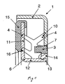
- Figure 1 shows a seal assembly 1, with a support body 2.
- the support body is made of metal and its shape is made by punching.
- On the support body is a positive and positive locking element 3 is attached.
- retaining element 3 and supporting body have congruent serrations which are shaped relative to one another.
- On the holding element 3, a sealing body 4 is fixed in a form-fitting manner, wherein the sealing body 4 has a dynamically sealing first sealing lip 5 and a statically sealing second sealing lip 10.
- the sealing body additionally has a dynamically acting third sealing lip 16.
- the first and the third sealing lips 5, 16 bear sealingly against a race 6.
- the race 6 consists of an axial flange 12 and a radial flange 11, wherein the dynamic sealing Sealing lips 5, 16 abut against the end face of the radial flange 11 with bias.
- the race 6 is positively, but not hindered in its rotational mobility relative to the support body 2, held on the support member 3.
- For the positive fixing of the raceway 6 has a groove 13 which is disposed on the inner peripheral side on the axial flange 12. In the groove 13 a clip element 14 engages, which is arranged on the holding element 3.
- the radial extent of the clip element 14 is dimensioned such that the clip element 14 after assembly is low friction in the groove 13 movable.
- a sensor 15 is arranged on the end facing away from the sealing body 4.
- the transmitter 15 is formed by an annular track, which consists of a magnetizable elastomer.
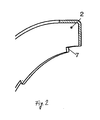
- FIG. 2 shows a support body 2 of a seal arrangement according to FIG. 1.
- the support body 2 is designed as a stamped part and has recesses 7 in the form of a serration on its inner circumference. Alternatively, openings distributed over the circumference can be arranged.
- FIG. 3 shows a retaining element 3 of a sealing arrangement according to FIG. 1.
- the retaining element 3 consists of a plastic, for example polyamide, and the shaping takes place in the injection-molding process.
- the holding element 3 has at one end face a serrated to the support body 2 serration 17.
- surveys may be arranged distributed over the circumference of the holding element 3, which engage in the openings of the support body 2.
- On the inner circumference of the holding element 3 are integrally and uniformly material Klips institute 14 arranged
- the holding element 3 has over The circumference distributed knobs 9, on which the sealing body 4 attachable and thus rotatably fixed.
- FIG. 4 shows a sealing body 4 of a sealing arrangement 4 according to FIG. 1.
- the sealing body 4 consists of a plastic, for example nitrile-butadiene rubber, polyacrylate elastomer or fluorinated rubber.
- the sealing body 4 has distributed over its circumference recesses 8, in which engage the knobs 9, which are distributed over the circumference of the holding element 3.
- Figure 5 shows a race 6 of a seal assembly 1.
- the race 6 is formed of a metallic stamped part.
Landscapes
- Engineering & Computer Science (AREA)
- General Engineering & Computer Science (AREA)
- Mechanical Engineering (AREA)
- Sealing Of Bearings (AREA)
- Sealing With Elastic Sealing Lips (AREA)
- Glass Compositions (AREA)
- Materials For Medical Uses (AREA)
- Sealing Battery Cases Or Jackets (AREA)
Abstract
Description
- Die Erfindung betrifft eine Dichtungsanordnung mit einem Tragkörper und einem Laufring, wobei zwischen Tragkörper und Laufring ein Dichtkörper angeordnet ist.
- Derartige Dichtungen sind allgemein bekannt. Häufig ist dabei der Laufring, beispielsweise durch einen umgebördelten Flansch am dem Tragkörper fixiert. Bei derartigen, auch als Kassettendichtungen, bezeichneten Dichtungsanordnurrgen ist der Dichtkörper zwischen dem Tragkörper und dem Laufring angeordnet und gegen grobe Verschmutzungen geschützt. Die Bestandteile der Dichtungsanordnung sind verliersicher aneinander befestigt, was insbesondere bei der Montage vorteilhaft ist. Der Dichtungskörper ist dabei stoffschlüssig an dem Tragkörper befestigt. Hierbei ist nachteilig, dass das stoffschlüssige von Dichtkörper und Tragring eine Vorbehandlung des Tragrings erfordert und an die Maßgenauigkeit des Tragkörpers hohe Anforderungen gestellt werden.
- Der Erfindung liegt die Aufgabe zugrunde, eine Dichtungsanordnung bereit zu stellen, die einfach zu montieren und einfach und kostengünstig herstellbar ist, wobei die Bauelemente der Dichtungsanordnung verliersicher aneinander befestigbar sein sollen.
- Diese Aufgabe wird mit den Merkmalen von Anspruch 1 gelöst. Auf vorteilhafte Ausgestaltungen nehmen die Unteransprüche Bezug.
- Zur Lösung der Aufgabe umfasst die Dichtungsanordnung einen Tragkörper an dem ein Halteelement befestigt ist, einen Dichtkörper, der an dem Haltelement befestigt ist, wobei der Dichtkörper zumindest eine dynamisch dichtende erste Dichtlippe aufweist, die an einem Laufring dichtend anliegt, wobei der Laufring an dem Halteelement formschlüssig gehalten ist.
Dadurch sind der Dichtkörper und der Laufring verliersicher an dem Tragring fixiert und können problemlos gemeinsam montiert werden. Das Halteelement ist kostengünstig herstellbar und stellt das Bindeglied dar, durch das Dichtkörper und Laufring an dem Tragkörper gehalten sind. Ein stoffschtüssiges Anbinden des Dichtkörpers an den Tragkörper entfällt. Dabei ist das Halteelement vorzugsweise aus einem Kunststoffspritzguss gebildet, wodurch das Halteelement kostengünstig in großen Stückzahlen herstellbar ist. Durch den Formschluss ist der Laufring reibungsarm und drehbar an dem Tragkörper fixiert. - Das Halteelement kann kraft- und/oder formschlüssig an dem Tragkörper befestigt sein. Dadurch kann das Halteelement einfach und ohne Zusatzstoffe an dem Tragkörper befestigt werden. Das Halteelement kann aus einem anderen Werkstoff als der Tragkörper hergestellt werden. Beispielsweise kann der Tragkörper aus Metall bestehen und die Formgebung kann durch Stanzen erfolgen. Das Halteelement kann aus Kunststonspntzguss bestehen, wodurch auch kompliziertere Geometrien kostengünstig herstellbar sind.
- Der Tragkörper kann am Innenumfang Ausnehmungen in Form einer Kerbverzahnung aufweisen. Durch die Kerbverzahnung sind das Halteelement und der Tragkörper drehfest miteinander verbunden. Dabei sind auch andere Geometrien denkbar, beispielsweise können über den Umfang Ausnehmungen in den Tragkörper eingebracht sein, in die Erhebungen des Halteelementes eingreifen. Das Halteelement weist dabei eine entsprechende Formgebung auf und kann an einer Stirnseite eine kongruent zu dem Tragkörper ausgebildete Kerbverzahnung aufweisen.
- Der Dichtkörper kann formschlüssig an dem Halteelement gehalten sein. Dadurch ist der Dichtkörper ebenfalls drehfest an dem Tragkörper fixiert. Die Montage kann besonders einfach durch Aufstecken erfolgen. Vorbehandlungen für haftende Verbindungen können entfallen und an den Tragkörper können geringere Anforderungen hinsichtlich der Maßhaltigkeit gestellt werden.
- Der Dichtkörper kann über seinen Umfang verteilt Ausnehmungen aufweisen, in die Noppen einsteckbar sind, die über den Umfang des Halteelementes verteilt sind. Die Noppen und die Ausnehmungen stellen dabei einfach herzustellende Elemente für eine formschlüssige Verbindung von Halteelement und Dichtkörper dar.
- Der Dichtkörper kann zumindest eine statisch dichtende zweite Dichtlippe aufweisen, die an dem Tragkörper dichtend anliegt. Die statische Dichtlippe stellt anstelle einer stoffschlüssigen Verbindung eine statische Abdichtung dar. Dabei ist vorteilhaft, dass die statische Dichtlippe federnd ausgebildet ist und dadurch die Anpressung der dynamischen Dichtlippe an den Laufring dosierbar ist. Des Weiteren ist die Dichtungsanordnung unempfindlicher gegenüber Unwuchten. Infolge der federnd ausgeführten statischen Dichtlippe erfolgt ein Nachstellen der dynamischen Dichtlippe bei Verschleiß derselben. Dadurch kann eine längere Nutzungsdauer der Dichtelemente erreicht werden.
- Der Laufring kann einen Radial- und einen Axialflansch aufweisen, wobei auf dem Axialflansch innenumfangsseitig eine Nut angeordnet ist. Eine Nut ist einfach und kostengünstig herstellbar und bildet einen Bestandteil der formschlüssigen Verbindung zwischen Halteelement und Laufring.
- Das Halteelement kann zumindest ein Klipselement aufweisen, welches in die Nut des Laufrings einrastbar ist. Das Klipselement des Halteelements rastet dabei in die Nut in des Laufrings ein, wodurch beide Elemente formschlüssig verbunden sind. Die axiale Erstreckung der Nut ist dabei kleiner als die der Nut des Laufrings, so dass das Klipselement nach der Montage frei beweglich in der Nut angeordnet ist und eine reibungsarme Bewegung ermöglicht ist.
- Der Laufring kann einen Messwertgeber umfassen. Dadurch ist eine Sensorik Platz sparend in die Dichtungsanordnung integriert. Die Anordnung ist besonders vorteilhaft, da der Laufring auf dem abzudichtenden Maschinenelement montiert ist und mit dessen Drehzahl rotiert. Dadurch kann die Drehzahl des Maschinenelementes einfach detektiert werden. Da die Dichtungsanordnung sehr kompakt ist, ergibt sich eine kompakte Kombination von Sensorik und Dichtungsfunktion.
- Der Messwertgeber kann auf der dem Dichtkörper abgewandten Stirnseite des Laufrings angeordnet sein. Dadurch kann der Messwertgeber besonders einfach durch einen Sensor ausgewertet werden.
- Der Messwertgeber kann durch eine kreisringförmige Spur gebildet sein, die aus einem magnetisierbaren Elastomer besteht Der Elastomer kann einfach und haltbar stoffschlüssig auf dem Laufring befestigt werden. Durch ein Magnetisierungswerkzeug kann die Spur flexibel mit einem magnetischen Muster versehen werden. Elektromagnetische Signale können durch Sensoren einfach erfasst und, beispielsweise digital, weiterverarbeitet werden.
- Einige Ausführungsbeispiele der erfindungsgemäßen Dichtungsanordnung werden nachfolgend anhand der Figuren näher beschrieben werden. Diese zeigen, jeweils schematisch:
- Fig. 1 eine erfindungsgemäße Dichtungsanordnung mit Messwertgeber;
- Fig. 2 den Tragring der Dichtungsanordnung;
- Fig. 3 das Halteelement der Dichtungsanordnung;
- Fig. 4 den Dichtkörper der Dichtungsanordnung;
- Fig. 5 den Laufring der Dichtungsanordnung.
- Figur 1 zeigt eine Dichtungsanordnung 1, mit einem Tragkörper 2. Der Tragkörper besteht aus Metall und dessen Formgebung erfolgt durch Stanzen. An dem Tragkörper ist kraft- und formschlüssig ein Halteelement 3 befestigt. Dazu weisen Haltelement 3 und Tragkörper kongruent zueinander geformte Kerbverzahnungen auf. An dem Halteelement 3 ist ein Dichtkörper 4 formschlüssig befestigt, wobei der Dichtkörper 4 eine dynamisch dichtende erste Dichtlippe 5 und eine statisch dichtende zweite Dichtlippe 10 aufweist. Zur Verbesserung der Dichteigenschaften hat der Dichtkörper zusätzlich eine dynamisch wirkende dritte Dichtlippe 16. Die erste und die dritte Dichtlippe 5, 16 liegen dichtend an einem Laufring 6 an. Der Laufring 6 besteht aus einem Axialflansch 12 und einen Radialflansch 11, wobei die dynamisch dichtenden Dichtlippen 5, 16 an der Stirnseite des Radialflansches 11 mit Vorspannung anliegen. Über den Axialflansch 12 ist der Laufring bei bestimmungsgemäßer Verwendung drehfest auf dem abzudichtenden Maschinenelement befestigt. Der Laufring 6 ist formschlüssig, aber nicht in seiner Drehbeweglichkeit gegenüber dem Tragkörper 2 gehindert, an dem Halteelement 3 gehalten. Zur formschlüssigen Fixierung weist der Laufring 6 eine Nut 13 auf, die innenumfangsseitig auf dem Axialflansch 12 angeordnet ist. In die Nut 13 rastet ein Klipselement 14 ein, welches an dem Halteelement 3 angeordnet ist. Dabei ist die radiale Erstreckung des Klipselementes 14 so bemessen, dass das Klipselement 14 nach der Montage reibungsarm in der Nut 13 beweglich ist. Vor der Montage erfolgt eine Anpressung des Klipselementes 14 aufgrund der Rückstellkräfte der Dichtlippen 5, 10, 16.
An dem Laufring 6 ist auf dessen dem Dichtkörper 4 abgewandten Stirnseite ein Messwertgeber 15 angeordnet. Der Messwertgeber 15 ist durch eine kreisringförmige Spur gebildet, die aus einem magnetisierbaren Elastomer besteht. - Figur 2 zeigt einen Tragkörper 2 einer Dichtungsanordnung gemäß Figur 1. Der Tragkörper 2 ist als Stanzteil ausgebildet und weist an seinem Innenumfang Ausnehmungen 7 in Form einer Kerbverzahnung auf. Alternativ können über den Umfang verteilt Durchbrechungen angeordnet sein.
- Figur 3 zeigt ein Halteelement 3 einer Dichtungsanordnung gemäß Figur 1. Das Halteelement 3 besteht aus einem Kunststoff, beispielsweise Polyamid, und die Formgebung erfolgt im Spritzgleßverfahren. Das Halteelement 3 weist an einer Stirnseite eine kongruent zu dem Tragkörper 2 ausgebildete Kerbverzahnung 17 auf. Alternativ können über den Umfang des Halteelementes 3 verteilt Erhebungen angeordnet sein, die in die Durchbrechungen des Tragkörpers 2 eingreifen. An dem Innenumfang des Halteelementes 3 sind einstückig und materialeinheitlich Klipselemente 14 angeordnet Das Haltelement 3 weist über den Umfang verteilt Noppen 9 auf, auf die der Dichtkörper 4 aufsteckbar und damit drehfest fixierbar ist.
- Figur 4 zeigt einen Dichtkörper 4 einer Dichtungsanordnung 4 gemäß Figur 1. Der Dichtkörper 4 besteht aus einem Kunststoff, beispielsweise Nitril-Butadien-Kautschuk, Polyacrylat-Elastomer oder Flourkautschuk. Der Dichtkörper 4 weist über seinen Umfang verteilt Ausnehmungen 8 auf, in die die Noppen 9 eingreifen, die über den Umfang des Halteelementes 3 verteilt sind.
- Figur 5 zeigt einen Laufring 6 einer Dichtungsanordnung 1. Der Laufring 6 ist aus einem metallischen Stanzteil gebildet.
Claims (12)
- Dichtungsanordnung (1), umfassend einen Tragkörper (2) an dem ein Halteelement (3) befestigt ist, einen Dichtkörper (4), der an dem Haltelement (3) befestigt ist, wobei der Dichtkörper (4) zumindest eine dynamisch dichtende erste Dichtlippe (5) aufweist, die an einem Laufring (6) dichtend anliegt, wobei der Laufring (6) an dem Halteelement (3) formschlüssig gehalten ist.
- Dichtungsanordnung nach Anspruch 1, dadurch gekennzeichnet, dass das Halteelement (3) kraft- und/oder formschlüssig an dem Tragkörper (2) befestigt ist.
- Dichtungsanordnung nach Anspruch 1 oder 2, dadurch gekennzeichnet, dass der Tragkörper (2) an seinem Innenumfang Ausnehmungen (7) in Form einer Kerbverzahnung aufweist.
- Dichtungsanordnung nach einem der Ansprüche 1 bis 3. dadurch gekennzeichnet, dass das Halteelement (3) an einer Stirnseite eine kongruent zu dem Tragkörper (2) ausgebildete Kerbverzahnung (17) aufweist.
- Dichtungsanordnung nach einem der Ansprüche 1 bis 4, dadurch gekennzeichnet, dass der Dichtkörper (4) formschlüssig an dem Halteelement (3) gehalten ist.
- Dichtungsanordnung nach einem der Ansprüche 1 bis 5, dadurch gekennzeichnet, dass der Dichtkörper (4) über seinen Umfang verteilt Ausnehmungen (8) aufweist, in die Noppen (9) einsteckbar sind, die über den Umfang des Halteelementes (3) verteilt sind.
- Dichtungsanordnung nach einem der Ansprüche 1 bis 6, dadurch gekennzeichnet, dass der Dichtkörper (4) zumindest eine statisch dichtende zweite Dichtlippe (10) aufweist, die an dem Tragkörper (2) dichtend anliegt.
- Dichtungsanordnung nach einem der Ansprüche 1 bis 7, dadurch gekennzeichnet, dass der Laufring (6) einen Radial- (11) und einen Axialflansch (12) aufweist, wobei auf dem Axialflansch (12) innenumfangsseitig eine Nut (13) angeordnet ist.
- Dichtungsanordnung nach einem der Ansprüche 1 bis 8, dadurch gekennzeichnet, dass das Halteelement (3) zumindest ein Klipselement (14) aufweist, welches in die Nut (13) des Laufrings (6) einrastbar ist.
- Dichtungsanordnung nach einem der Ansprüche 1 bis 9, dadurch gekennzeichnet, dass der Laufring (6) einen Messwertgeber (15) umfasst.
- Dichtungsanordnung nach Anspruch 10, dadurch gekennzeichnet, dass der Messwertgeber (15) auf der dem Dichtkörper (4) abgewandten Stirnseite des Laufrings (6) angeordnet ist.
- Dichtungsanordnung nach Anspruch 10 oder 11, dadurch gekennzeichnet, dass der Messwertgeber (15) durch eine kreisringförmige Spur gebildet ist, die aus einem magnetisierbaren Elastomer besteht.
Priority Applications (3)
| Application Number | Priority Date | Filing Date | Title |
|---|---|---|---|
| EP05025960A EP1790885B1 (de) | 2005-11-29 | 2005-11-29 | Dichtungsanordnung |
| DE502005003496T DE502005003496D1 (de) | 2005-11-29 | 2005-11-29 | Dichtungsanordnung |
| AT05025960T ATE390584T1 (de) | 2005-11-29 | 2005-11-29 | Dichtungsanordnung |
Applications Claiming Priority (1)
| Application Number | Priority Date | Filing Date | Title |
|---|---|---|---|
| EP05025960A EP1790885B1 (de) | 2005-11-29 | 2005-11-29 | Dichtungsanordnung |
Publications (2)
| Publication Number | Publication Date |
|---|---|
| EP1790885A1 true EP1790885A1 (de) | 2007-05-30 |
| EP1790885B1 EP1790885B1 (de) | 2008-03-26 |
Family
ID=36046827
Family Applications (1)
| Application Number | Title | Priority Date | Filing Date |
|---|---|---|---|
| EP05025960A Expired - Lifetime EP1790885B1 (de) | 2005-11-29 | 2005-11-29 | Dichtungsanordnung |
Country Status (3)
| Country | Link |
|---|---|
| EP (1) | EP1790885B1 (de) |
| AT (1) | ATE390584T1 (de) |
| DE (1) | DE502005003496D1 (de) |
Citations (3)
| Publication number | Priority date | Publication date | Assignee | Title |
|---|---|---|---|---|
| DE3204989A1 (de) * | 1982-02-12 | 1983-09-01 | Fa. Carl Freudenberg, 6940 Weinheim | Kassettendichtung |
| US4596394A (en) * | 1984-04-13 | 1986-06-24 | Firma Carl Freudenberg | Cartridge seal |
| DE10320471A1 (de) * | 2002-06-13 | 2004-01-15 | Skf Industrie S.P.A. | Abdichtungsvorrichtung mit integriertem Tonrad |
-
2005
- 2005-11-29 EP EP05025960A patent/EP1790885B1/de not_active Expired - Lifetime
- 2005-11-29 DE DE502005003496T patent/DE502005003496D1/de not_active Expired - Lifetime
- 2005-11-29 AT AT05025960T patent/ATE390584T1/de not_active IP Right Cessation
Patent Citations (3)
| Publication number | Priority date | Publication date | Assignee | Title |
|---|---|---|---|---|
| DE3204989A1 (de) * | 1982-02-12 | 1983-09-01 | Fa. Carl Freudenberg, 6940 Weinheim | Kassettendichtung |
| US4596394A (en) * | 1984-04-13 | 1986-06-24 | Firma Carl Freudenberg | Cartridge seal |
| DE10320471A1 (de) * | 2002-06-13 | 2004-01-15 | Skf Industrie S.P.A. | Abdichtungsvorrichtung mit integriertem Tonrad |
Also Published As
| Publication number | Publication date |
|---|---|
| DE502005003496D1 (de) | 2008-05-08 |
| ATE390584T1 (de) | 2008-04-15 |
| EP1790885B1 (de) | 2008-03-26 |
Similar Documents
| Publication | Publication Date | Title |
|---|---|---|
| EP0725242B1 (de) | Dichtungsanordnung | |
| DE69609641T2 (de) | Kodiervorrichtung für Geschwindigkeitsmessaufnehmer sowie ein mit einer solchen Vorrichtung versehenes Wälzlager | |
| DE68903331T2 (de) | Drehende dichtung mit integriertem magnetischen kodierer, insbesondere fuer waelzlager mit messwertgeber. | |
| DE102008002218A1 (de) | Abdichtvorrichtung | |
| DE102014208422B4 (de) | Radlagereinheit | |
| DE102018207056A1 (de) | Kreuzgelenklager | |
| WO2022053636A1 (de) | Dichtungseinrichtung und dichtungsanordnung mit sensorik zur zustandsüberwachung | |
| DE102020212123A1 (de) | Sensor und Verfahren zur Herstellung eines Sensors | |
| DE102018102203A1 (de) | Lageranordnung mit integrierter Sensoreinrichtung zur Erfassung von Relativbewegungen | |
| DE102017108717A1 (de) | Scheibenbremse für ein Nutzfahrzeug | |
| DE112019001237T5 (de) | Dichtungsvorrichtung und Verfahren zu deren Montage | |
| EP2618032B1 (de) | Wellendichtung, insbesondere Radialwellendichtung | |
| DE19636173B4 (de) | Wälzlager mit Drehzahlmeßeinrichtung | |
| DE102013203622B4 (de) | Radlageranordnung mit verstärktem Innenring und seitlicher Messvorrichtung | |
| DE102013215621A1 (de) | Sensoranordnung eines Radlagers | |
| DE112017001397T5 (de) | Radlagervorrichtung | |
| EP1790885B1 (de) | Dichtungsanordnung | |
| DE10338960A1 (de) | Dichtungsanordnung mit Encoder und Magnetisierungskopf für den Encoder | |
| WO2016124179A1 (de) | Radlagereinheit | |
| DE10050983B4 (de) | Axialwellendichtung in einer Gehäusebohrung mit einem mit der Welle fest verbundenen umlaufenden Innenteil | |
| DE202005005260U1 (de) | Vorrichtung zur Messung von Drehbewegungen eines Radlagers | |
| DE112006000366B4 (de) | Radlageranordnung mit einem Encoder | |
| EP2037161B1 (de) | Dichtung mit integriertem Sensor und Dichtungsanordnung mit dieser Dichtung | |
| EP0999448B1 (de) | Kassettendichtung mit Geschwindigkeitssensor | |
| EP3208454A1 (de) | Kurbelwellen-dichtflansch |
Legal Events
| Date | Code | Title | Description |
|---|---|---|---|
| PUAI | Public reference made under article 153(3) epc to a published international application that has entered the european phase |
Free format text: ORIGINAL CODE: 0009012 |
|
| 17P | Request for examination filed |
Effective date: 20060407 |
|
| AK | Designated contracting states |
Kind code of ref document: A1 Designated state(s): AT BE BG CH CY CZ DE DK EE ES FI FR GB GR HU IE IS IT LI LT LU LV MC NL PL PT RO SE SI SK TR |
|
| AX | Request for extension of the european patent |
Extension state: AL BA HR MK YU |
|
| GRAP | Despatch of communication of intention to grant a patent |
Free format text: ORIGINAL CODE: EPIDOSNIGR1 |
|
| GRAS | Grant fee paid |
Free format text: ORIGINAL CODE: EPIDOSNIGR3 |
|
| AKX | Designation fees paid |
Designated state(s): AT BE BG CH CY CZ DE DK EE ES FI FR GB GR HU IE IS IT LI LT LU LV MC NL PL PT RO SE SI SK TR |
|
| GRAA | (expected) grant |
Free format text: ORIGINAL CODE: 0009210 |
|
| AK | Designated contracting states |
Kind code of ref document: B1 Designated state(s): AT BE BG CH CY CZ DE DK EE ES FI FR GB GR HU IE IS IT LI LT LU LV MC NL PL PT RO SE SI SK TR |
|
| REG | Reference to a national code |
Ref country code: GB Ref legal event code: FG4D Free format text: NOT ENGLISH |
|
| REG | Reference to a national code |
Ref country code: IE Ref legal event code: FG4D Free format text: LANGUAGE OF EP DOCUMENT: GERMAN Ref country code: CH Ref legal event code: EP |
|
| REF | Corresponds to: |
Ref document number: 502005003496 Country of ref document: DE Date of ref document: 20080508 Kind code of ref document: P |
|
| PG25 | Lapsed in a contracting state [announced via postgrant information from national office to epo] |
Ref country code: FI Free format text: LAPSE BECAUSE OF FAILURE TO SUBMIT A TRANSLATION OF THE DESCRIPTION OR TO PAY THE FEE WITHIN THE PRESCRIBED TIME-LIMIT Effective date: 20080326 |
|
| NLV1 | Nl: lapsed or annulled due to failure to fulfill the requirements of art. 29p and 29m of the patents act | ||
| PG25 | Lapsed in a contracting state [announced via postgrant information from national office to epo] |
Ref country code: LV Free format text: LAPSE BECAUSE OF FAILURE TO SUBMIT A TRANSLATION OF THE DESCRIPTION OR TO PAY THE FEE WITHIN THE PRESCRIBED TIME-LIMIT Effective date: 20080326 Ref country code: SI Free format text: LAPSE BECAUSE OF FAILURE TO SUBMIT A TRANSLATION OF THE DESCRIPTION OR TO PAY THE FEE WITHIN THE PRESCRIBED TIME-LIMIT Effective date: 20080326 Ref country code: PL Free format text: LAPSE BECAUSE OF FAILURE TO SUBMIT A TRANSLATION OF THE DESCRIPTION OR TO PAY THE FEE WITHIN THE PRESCRIBED TIME-LIMIT Effective date: 20080326 |
|
| REG | Reference to a national code |
Ref country code: IE Ref legal event code: FD4D |
|
| PG25 | Lapsed in a contracting state [announced via postgrant information from national office to epo] |
Ref country code: SE Free format text: LAPSE BECAUSE OF FAILURE TO SUBMIT A TRANSLATION OF THE DESCRIPTION OR TO PAY THE FEE WITHIN THE PRESCRIBED TIME-LIMIT Effective date: 20080626 Ref country code: SK Free format text: LAPSE BECAUSE OF FAILURE TO SUBMIT A TRANSLATION OF THE DESCRIPTION OR TO PAY THE FEE WITHIN THE PRESCRIBED TIME-LIMIT Effective date: 20080326 Ref country code: ES Free format text: LAPSE BECAUSE OF FAILURE TO SUBMIT A TRANSLATION OF THE DESCRIPTION OR TO PAY THE FEE WITHIN THE PRESCRIBED TIME-LIMIT Effective date: 20080707 Ref country code: CZ Free format text: LAPSE BECAUSE OF FAILURE TO SUBMIT A TRANSLATION OF THE DESCRIPTION OR TO PAY THE FEE WITHIN THE PRESCRIBED TIME-LIMIT Effective date: 20080326 Ref country code: PT Free format text: LAPSE BECAUSE OF FAILURE TO SUBMIT A TRANSLATION OF THE DESCRIPTION OR TO PAY THE FEE WITHIN THE PRESCRIBED TIME-LIMIT Effective date: 20080901 |
|
| PG25 | Lapsed in a contracting state [announced via postgrant information from national office to epo] |
Ref country code: NL Free format text: LAPSE BECAUSE OF FAILURE TO SUBMIT A TRANSLATION OF THE DESCRIPTION OR TO PAY THE FEE WITHIN THE PRESCRIBED TIME-LIMIT Effective date: 20080326 Ref country code: RO Free format text: LAPSE BECAUSE OF FAILURE TO SUBMIT A TRANSLATION OF THE DESCRIPTION OR TO PAY THE FEE WITHIN THE PRESCRIBED TIME-LIMIT Effective date: 20080326 |
|
| PG25 | Lapsed in a contracting state [announced via postgrant information from national office to epo] |
Ref country code: IS Free format text: LAPSE BECAUSE OF FAILURE TO SUBMIT A TRANSLATION OF THE DESCRIPTION OR TO PAY THE FEE WITHIN THE PRESCRIBED TIME-LIMIT Effective date: 20080726 |
|
| EN | Fr: translation not filed | ||
| PG25 | Lapsed in a contracting state [announced via postgrant information from national office to epo] |
Ref country code: IE Free format text: LAPSE BECAUSE OF FAILURE TO SUBMIT A TRANSLATION OF THE DESCRIPTION OR TO PAY THE FEE WITHIN THE PRESCRIBED TIME-LIMIT Effective date: 20080326 Ref country code: DK Free format text: LAPSE BECAUSE OF FAILURE TO SUBMIT A TRANSLATION OF THE DESCRIPTION OR TO PAY THE FEE WITHIN THE PRESCRIBED TIME-LIMIT Effective date: 20080326 Ref country code: LT Free format text: LAPSE BECAUSE OF FAILURE TO SUBMIT A TRANSLATION OF THE DESCRIPTION OR TO PAY THE FEE WITHIN THE PRESCRIBED TIME-LIMIT Effective date: 20080326 |
|
| PLBE | No opposition filed within time limit |
Free format text: ORIGINAL CODE: 0009261 |
|
| STAA | Information on the status of an ep patent application or granted ep patent |
Free format text: STATUS: NO OPPOSITION FILED WITHIN TIME LIMIT |
|
| 26N | No opposition filed |
Effective date: 20081230 |
|
| PG25 | Lapsed in a contracting state [announced via postgrant information from national office to epo] |
Ref country code: EE Free format text: LAPSE BECAUSE OF FAILURE TO SUBMIT A TRANSLATION OF THE DESCRIPTION OR TO PAY THE FEE WITHIN THE PRESCRIBED TIME-LIMIT Effective date: 20080326 Ref country code: BG Free format text: LAPSE BECAUSE OF FAILURE TO SUBMIT A TRANSLATION OF THE DESCRIPTION OR TO PAY THE FEE WITHIN THE PRESCRIBED TIME-LIMIT Effective date: 20080626 Ref country code: FR Free format text: LAPSE BECAUSE OF FAILURE TO SUBMIT A TRANSLATION OF THE DESCRIPTION OR TO PAY THE FEE WITHIN THE PRESCRIBED TIME-LIMIT Effective date: 20090116 |
|
| BERE | Be: lapsed |
Owner name: CARL FREUDENBERG K.G. Effective date: 20081130 |
|
| PG25 | Lapsed in a contracting state [announced via postgrant information from national office to epo] |
Ref country code: MC Free format text: LAPSE BECAUSE OF NON-PAYMENT OF DUE FEES Effective date: 20081130 |
|
| PG25 | Lapsed in a contracting state [announced via postgrant information from national office to epo] |
Ref country code: IT Free format text: LAPSE BECAUSE OF FAILURE TO SUBMIT A TRANSLATION OF THE DESCRIPTION OR TO PAY THE FEE WITHIN THE PRESCRIBED TIME-LIMIT Effective date: 20080326 |
|
| PG25 | Lapsed in a contracting state [announced via postgrant information from national office to epo] |
Ref country code: BE Free format text: LAPSE BECAUSE OF NON-PAYMENT OF DUE FEES Effective date: 20081130 Ref country code: CY Free format text: LAPSE BECAUSE OF FAILURE TO SUBMIT A TRANSLATION OF THE DESCRIPTION OR TO PAY THE FEE WITHIN THE PRESCRIBED TIME-LIMIT Effective date: 20080326 |
|
| PG25 | Lapsed in a contracting state [announced via postgrant information from national office to epo] |
Ref country code: AT Free format text: LAPSE BECAUSE OF NON-PAYMENT OF DUE FEES Effective date: 20081129 |
|
| REG | Reference to a national code |
Ref country code: CH Ref legal event code: PL |
|
| GBPC | Gb: european patent ceased through non-payment of renewal fee |
Effective date: 20091129 |
|
| PG25 | Lapsed in a contracting state [announced via postgrant information from national office to epo] |
Ref country code: LU Free format text: LAPSE BECAUSE OF NON-PAYMENT OF DUE FEES Effective date: 20081129 Ref country code: HU Free format text: LAPSE BECAUSE OF FAILURE TO SUBMIT A TRANSLATION OF THE DESCRIPTION OR TO PAY THE FEE WITHIN THE PRESCRIBED TIME-LIMIT Effective date: 20080927 |
|
| PG25 | Lapsed in a contracting state [announced via postgrant information from national office to epo] |
Ref country code: TR Free format text: LAPSE BECAUSE OF FAILURE TO SUBMIT A TRANSLATION OF THE DESCRIPTION OR TO PAY THE FEE WITHIN THE PRESCRIBED TIME-LIMIT Effective date: 20080326 |
|
| PG25 | Lapsed in a contracting state [announced via postgrant information from national office to epo] |
Ref country code: GR Free format text: LAPSE BECAUSE OF FAILURE TO SUBMIT A TRANSLATION OF THE DESCRIPTION OR TO PAY THE FEE WITHIN THE PRESCRIBED TIME-LIMIT Effective date: 20080627 Ref country code: CH Free format text: LAPSE BECAUSE OF NON-PAYMENT OF DUE FEES Effective date: 20091130 Ref country code: LI Free format text: LAPSE BECAUSE OF NON-PAYMENT OF DUE FEES Effective date: 20091130 |
|
| PG25 | Lapsed in a contracting state [announced via postgrant information from national office to epo] |
Ref country code: GB Free format text: LAPSE BECAUSE OF NON-PAYMENT OF DUE FEES Effective date: 20091129 |
|
| PGFP | Annual fee paid to national office [announced via postgrant information from national office to epo] |
Ref country code: DE Payment date: 20101201 Year of fee payment: 6 |
|
| REG | Reference to a national code |
Ref country code: DE Ref legal event code: R119 Ref document number: 502005003496 Country of ref document: DE Effective date: 20130601 |
|
| PG25 | Lapsed in a contracting state [announced via postgrant information from national office to epo] |
Ref country code: DE Free format text: LAPSE BECAUSE OF NON-PAYMENT OF DUE FEES Effective date: 20130601 |