EP1790545A2 - Parking-brake-operation indicator and method of adjusting parking brake - Google Patents
Parking-brake-operation indicator and method of adjusting parking brake Download PDFInfo
- Publication number
- EP1790545A2 EP1790545A2 EP06124938A EP06124938A EP1790545A2 EP 1790545 A2 EP1790545 A2 EP 1790545A2 EP 06124938 A EP06124938 A EP 06124938A EP 06124938 A EP06124938 A EP 06124938A EP 1790545 A2 EP1790545 A2 EP 1790545A2
- Authority
- EP
- European Patent Office
- Prior art keywords
- brake
- lever
- parking
- switch
- cable
- Prior art date
- Legal status (The legal status is an assumption and is not a legal conclusion. Google has not performed a legal analysis and makes no representation as to the accuracy of the status listed.)
- Granted
Links
- 238000000034 method Methods 0.000 title claims description 7
- 230000007246 mechanism Effects 0.000 description 3
- 230000008569 process Effects 0.000 description 2
- 238000005299 abrasion Methods 0.000 description 1
- 230000008859 change Effects 0.000 description 1
- 239000004020 conductor Substances 0.000 description 1
- 230000006870 function Effects 0.000 description 1
- 239000010687 lubricating oil Substances 0.000 description 1
- 239000003921 oil Substances 0.000 description 1
Images
Classifications
-
- B—PERFORMING OPERATIONS; TRANSPORTING
- B60—VEHICLES IN GENERAL
- B60T—VEHICLE BRAKE CONTROL SYSTEMS OR PARTS THEREOF; BRAKE CONTROL SYSTEMS OR PARTS THEREOF, IN GENERAL; ARRANGEMENT OF BRAKING ELEMENTS ON VEHICLES IN GENERAL; PORTABLE DEVICES FOR PREVENTING UNWANTED MOVEMENT OF VEHICLES; VEHICLE MODIFICATIONS TO FACILITATE COOLING OF BRAKES
- B60T17/00—Component parts, details, or accessories of power brake systems not covered by groups B60T8/00, B60T13/00 or B60T15/00, or presenting other characteristic features
- B60T17/18—Safety devices; Monitoring
- B60T17/22—Devices for monitoring or checking brake systems; Signal devices
-
- B—PERFORMING OPERATIONS; TRANSPORTING
- B60—VEHICLES IN GENERAL
- B60T—VEHICLE BRAKE CONTROL SYSTEMS OR PARTS THEREOF; BRAKE CONTROL SYSTEMS OR PARTS THEREOF, IN GENERAL; ARRANGEMENT OF BRAKING ELEMENTS ON VEHICLES IN GENERAL; PORTABLE DEVICES FOR PREVENTING UNWANTED MOVEMENT OF VEHICLES; VEHICLE MODIFICATIONS TO FACILITATE COOLING OF BRAKES
- B60T7/00—Brake-action initiating means
- B60T7/02—Brake-action initiating means for personal initiation
- B60T7/08—Brake-action initiating means for personal initiation hand actuated
- B60T7/10—Disposition of hand control
- B60T7/102—Disposition of hand control by means of a tilting lever
-
- F—MECHANICAL ENGINEERING; LIGHTING; HEATING; WEAPONS; BLASTING
- F16—ENGINEERING ELEMENTS AND UNITS; GENERAL MEASURES FOR PRODUCING AND MAINTAINING EFFECTIVE FUNCTIONING OF MACHINES OR INSTALLATIONS; THERMAL INSULATION IN GENERAL
- F16D—COUPLINGS FOR TRANSMITTING ROTATION; CLUTCHES; BRAKES
- F16D66/00—Arrangements for monitoring working conditions, e.g. wear, temperature
-
- F—MECHANICAL ENGINEERING; LIGHTING; HEATING; WEAPONS; BLASTING
- F16—ENGINEERING ELEMENTS AND UNITS; GENERAL MEASURES FOR PRODUCING AND MAINTAINING EFFECTIVE FUNCTIONING OF MACHINES OR INSTALLATIONS; THERMAL INSULATION IN GENERAL
- F16D—COUPLINGS FOR TRANSMITTING ROTATION; CLUTCHES; BRAKES
- F16D66/00—Arrangements for monitoring working conditions, e.g. wear, temperature
- F16D2066/003—Position, angle or speed
-
- Y—GENERAL TAGGING OF NEW TECHNOLOGICAL DEVELOPMENTS; GENERAL TAGGING OF CROSS-SECTIONAL TECHNOLOGIES SPANNING OVER SEVERAL SECTIONS OF THE IPC; TECHNICAL SUBJECTS COVERED BY FORMER USPC CROSS-REFERENCE ART COLLECTIONS [XRACs] AND DIGESTS
- Y10—TECHNICAL SUBJECTS COVERED BY FORMER USPC
- Y10T—TECHNICAL SUBJECTS COVERED BY FORMER US CLASSIFICATION
- Y10T74/00—Machine element or mechanism
- Y10T74/20—Control lever and linkage systems
- Y10T74/20576—Elements
- Y10T74/20582—Levers
-
- Y—GENERAL TAGGING OF NEW TECHNOLOGICAL DEVELOPMENTS; GENERAL TAGGING OF CROSS-SECTIONAL TECHNOLOGIES SPANNING OVER SEVERAL SECTIONS OF THE IPC; TECHNICAL SUBJECTS COVERED BY FORMER USPC CROSS-REFERENCE ART COLLECTIONS [XRACs] AND DIGESTS
- Y10—TECHNICAL SUBJECTS COVERED BY FORMER USPC
- Y10T—TECHNICAL SUBJECTS COVERED BY FORMER US CLASSIFICATION
- Y10T74/00—Machine element or mechanism
- Y10T74/20—Control lever and linkage systems
- Y10T74/20576—Elements
- Y10T74/20636—Detents
- Y10T74/20672—Lever engaging rack
- Y10T74/20696—Finger lever release
- Y10T74/20702—Slidable
Definitions
- the present invention relates to a parking-brake-operation indicator for a parking brake that performs braking operation through a cable by manually operating a brake-operation tool of a vehicle.
- the present invention also relates to a method of adjusting a parking brake in a vehicle having such operation indicator.
- Japanese Patent Application Publication No. 60-25841 discloses that in a structure that an operating force of the parking brake is transmitted to the brake portion of the parking brake through a control cable, a signal for the braking force of the parking brake and a signal for inclination of a vehicle are compared and then a signal for driving an indicator is outputted. According to this art, it is confirmed that the parking brake is operated with the braking force corresponding to the inclination of the vehicle when the vehicle is parked on a slope.
- Japanese Patent Application Publication No. 60-25841 also discloses a deformation sensor connected to a brake shoe or a brake pad for sensing deformation, a tension sensor for sensing tension of a control cable and a position sensor provided at a parking lever (or a brake-operation tool), as a braking-force sensor for sensing a braking force of the parking brake.
- Japanese Utility Model Application Publication No. 61-85565 discloses that a strain gauge is attached to a piston of the brake pad that is connected to the handle of the parking brake and operable to press a brake disc, thereby sensing deformation due to the pressure of the braking pad with respect to the brake disc.
- Japanese Utility Model Application Publication No. 61-85565 discloses a structure including an amplifier that outputs amplified electric voltage commensurate with a braking pressure based on resistance change of the strain gauge and a comparator that switches to ON when the outputted electric voltage becomes a reference value or less. According to this structure, an operation lamp is not turned off until locking state is fully released. Thus, the operation lamp indicates to an operator that the parking brake is fully released.
- the tension of the cable that connects the brake-operation tool to the parking brake may be adjusted in order to adjust the braking force of the parking brake or the operating force of the brake-operation tool.
- the cable may be excessively tightened depending on the adjustment of the cable tension, which causes narrow clearances between the brake discs of the parking brake.
- a mechanism for adjusting the cable tension is often located at a distance from the brake discs.
- the cable tends to be easily excessively tightened.
- drag torque of the parking brake becomes large due to oil viscosity, especially in a wet type multi-disc brake.
- the braking-force sensor of Japanese Patent Application Publication No. 60-25841 and the strain gauge of Japanese Utility Model Application Publication No. 61-85565 cannot detect that the clearances between the parking discs of the parking brake are narrow.
- a parking-brake-operation indicator includes a lever having a pressing portion for pressing a brake disc of a parking brake to press contact the brake disc, a cable operable to draw the lever, a brake-operation tool connected to the cable, a switch for detecting a position of the lever and an indicating means for indicating operation of the parking brake.
- the present invention also provides a method of adjusting a parking brake in a vehicle that includes a lever having a pressing portion for pressing a brake disc of a parking brake to press contact the brake disc, a spring for urging the lever in a brake-release direction which causes braking of the parking brake to be released, a cable operable to draw the lever and a brake-operation tool connected to the cable.
- the method includes the steps of providing a switch for detecting a position of the lever to the vehicle; providing an indicating means for indicating state of the switch to the vehicle; adjusting tension of the cable with the brake-operation tool located in its brake position; and confirming that the lever is located in its brake-release position with the brake-operation tool located in its brake-release position.
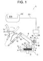
- FIG. 1 is a schematic view of a parking-brake-operation indicator according to the preferred embodiment of the present invention.
- FIG. 1 illustrates the parking-brake-operation indicator 1 provided in a forklift truck as a vehicle.
- the forklift truck includes a parking brake 3 for braking a member (a drive shaft 2 in the preferred embodiment) constituting a driving-force-transmission path from an engine (not shown) to wheels (not shown).
- the parking brake 3 has a brake housing 5 that partially covers the drive shaft 2 that is rotatably supported at the bottom surface of the forklift truck. Brake discs 4 that are engaged with the drive shaft 2 so as to axially move relative to and so as not to rotate with the drive shaft 2 and brake discs 4 that are engaged with the brake housing 5 so as to axially move relative to and so as not to rotate with the brake housing 5 are alternately arranged in the brake housing 5.
- the brake housing 5 is filled with lubricating oil, thus the parking brake 3 being formed as a wet type.
- a pressing plate 6 is disposed on one side (or an upper side in FIG. 1) of the stacked brake discs 4.
- a support 7 is located adjacently to the pressing plate 6 for pivotally supporting a lever 8.
- the support 7 is made of a plate having a bent portion at its appropriate portion.
- the lever 8 has a base 9 that is rotatably supported by the support 7, a lever body 10 that projects from the base 9 and a fork (or a pressing portion) 11 that projects from the base 9 and whose distal end is located adjacently to the pressing plate 6.
- a return spring (or an urging spring) 12 is disposed adjacently to the base 9.
- the return spring 12 is typically a coil spring that is hitched at one end to the lever body 10 and at the other end to the bent portion of the support 7. Thus, an urging force is constantly applied to the lever body 10 (the lever 8) in a direction that causes the fork 11 not to press the brake discs 4.
- a control cable 13 is connected at one end to the distal end of the lever body 10.
- the control cable 13 passes through inside an instrumental panel 25 that is provided in front of the operator's seat of the forklift truck.
- the control cable 13 is connected at the other end to a parking brake lever (or a brake-operation tool) 14 that is located adjacently to the operator's seat.
- the parking brake lever 14 is of a toggle type that is pivotally moveable between a brake-release position and a brake position.
- a length adjuster 24 is provided on the part of the control cable 13 that is located inside the instrumental panel 25 adjacently to the connection of the control cable 13 to the parking brake lever 14.
- the length of the control cable 13 is adjustable by the length adjuster 24.
- the structure of the length adjuster 24 is various and may be a combination of bolt and nut.
- a switch 15 is provided as a sensor for detecting the position (or a brake-release position) of the lever body 10 of the lever 8 that is indicated by the solid line in FIG. 1.
- the switch 15 has a contactor 16 that is contactable with the lever body 10, a tubular contactor support 17 that supports the contactor 16 so that the contactor 16 is movable for a certain small stroke and a switch housing 18 that accommodates therein a switch circuit that switches between ON and OFF according to the position of the contactor 16.
- An external thread is formed on the outer circumferential surface of the contactor support 17.
- Two disc nuts 19 are screwed on the external thread of the contactor support 17.
- the disc nuts 19 respectively have flanges between which the bent portion of the support 7 is sandwiched thereby to fix the contactor support 17 to the support 7.
- the position where the contactor support 17 is fixed to the support 7 or the position of the switch 15 is adjusted in the axial direction of the contactor support 17 by appropriately rotating the disc nuts 19 on the contactor support 17.
- An output-signal cable 20 is drawn from the switch housing 18 of the switch 15 and electrically connected to an indication controller 21.
- the indication controller 21 is of a microcomputer type having a central processing unit (CPU), a read-only memory (ROM), a random access memory (RAM) and the like.
- the indication controller 21 is connected through a signal cable 23 to a meter display (or an indicating means) 22 that is disposed adjacently to the operator's seat.
- the indication controller 21 controls a "P" lamp (or a warning lamp) of the meter display 22 to be turned off.
- the indication controller 21 controls the "P" lamp of the meter display 22 to be turned on.
- the lever 8 When the parking brake lever 14 is located in its brake-release position as indicated by the solid line in FIG. 1, the lever 8 is pivoted by the urging force of the return spring 12 in a brake-release direction which causes braking of the parking brake 3 to be released or clockwise in FIG. 1 so that the lever body 10 contacts with and presses the contactor 16 of the switch 15. Thus, the contactor 16 is pressed to its stroke end as indicated by the solid line in FIG. 1. In other words, the contactor 16 at its solid-line position functions as a stopper to prevent the lever 8 from pivoting further in the brake-release direction.
- the fork 11 of the lever 8 does not press the brake discs 4 through the pressing plate 6.
- the switch 15 senses that the contactor 16 is pressed and switches to OFF.
- the indication controller 21 detects this and turn off the "P" lamp of the meter display 22. Therefore, an operator at the operator's seat notices that the parking brake 3 is not operated by confirming that the "P" lamp is turned off.
- the operator puts his or her hand on the parking brake lever 14 and pulls it in the direction of the arrow in FIG. 1. Accordingly, the lever body 10 of the lever 8 is drawn through the control cable 13 and the lever 8 is pivoted on the base 9 anticlockwise or in the direction of the arrow in FIG. 1.
- the lever body 10 moves away from the contactor 16 of the switch 15 and the fork 11 presses the brake discs 4 through the pressing plate 6.
- the clearances between the brake discs 4 disappear and the brake discs 4 are brought into press contact with each other, thereby providing a friction braking force to the drive shaft 2.
- the parking brake lever 14 is locked by an appropriate lock mechanism, so that the vehicle is braked so as not to move despite the intention of the operator.
- the pressed contactor 16 is released and moved by a return spring (not shown) leftward in FIG. 1 from the pressed position so that the switch 15 switches to ON.
- the indication controller 21 detects this and turns on the "P" lamp of the meter display 22. Therefore, it is indicated to the operator at the operator's seat that the parking brake 3 is operated.
- the following will describe process for adjusting the operating force of the parking brake lever 14 and the braking force of the parking brake 3 in the above structure.
- the adjustment is carried out by accessing to the inside of the instrumental panel 25 and screwing the length adjuster 24 onto the control cable 13.
- the parking brake lever 14 is inclined to its brake position indicated by the chain double-dashed line in FIG. 1.
- the length adjuster 24 is screwed onto the control cable 13 to adjust the tension of the control cable 13 so that a desired braking force at the brake discs 4 is obtained.
- the length adjuster 24 may be excessively screwed onto the control cable 13. If so, the lever 8 may be still dragged by the control cable 13 in the brake direction even when the parking brake lever 14 is returned to its brake-release position. Thus, the clearances between the brake discs 4 are excessively small and hence drag torque becomes large.
- the parking brake lever 14 is returned to its brake-release position and it is confirmed that the "P" lamp of the meter display 22 is turned off after the above screwing work. If the "P" lamp is not turned off after the parking brake lever 14 is returned to its brake-release position, this means that the lever body 10 is separated from the switch 15 due to the excessive tension of the control cable 13, namely, that the lever 8 fails to be returned to its brake-release position thereby to make the clearances between the brake discs 4 narrow.
- the length adjuster 24 is readjusted so that the excessive tension of the control cable 13 is released and it is reconfirmed whether the "P" lamp is turned off with the parking brake lever 14 located in its brake-release position. By so doing, the braking force of the parking brake is appropriately adjusted while the appropriate clearances between the brake discs 4 are ensured in the brake-release state of the parking brake 3.
- the parking-brake-operation indicator 1 of the preferred embodiment includes the lever 8 having the fork 11 for pressing the brake discs 4 of the parking brake 3 to press contact the brake discs 4, the control cable 13 operable to drag the lever 8, the parking brake lever 14 connected to the control cable 13, the switch 15 for detecting the position of the lever 8 and the meter display 22 for indicating the operation of the parking brake 3 according to the state of the switch 15.
- the parking-brake-operation indicator 1 of the preferred embodiment includes the return spring 12 for urging the lever 8 in the brake-release direction, and the switch 15 is configured to restrict the movement of the lever 8 in the brake-release direction by the contactor 16 in a state of contacting with the lever 8.
- the position of the contactor 16 (or the switch 15) is adjusted by rotating the disc nuts 19, thereby adjusting the brake-release position of the lever 8.
- the brake-release position of the lever 8 is adjusted through a simple structure. It is considered that the adjustment of the brake-release position of the lever 8 is carried out just before shipment of the vehicle or depending on abrasion of the brake discs 4.
- the parking brake is adjusted as follows. With the parking brake lever 14 inclined in its brake position indicated by the chain double-dashed line in FIG. 1, the tension of the control cable 13 is adjusted. Then, the parking brake lever 14 is inclined to its brake-release position indicated by the solid line in FIG. 1 and it is confirmed that the "P" lamp of the meter display 22 is turned off to ensure that the lever 8 is located in its brake-release position indicated by the solid line in FIG. 1.
- the press contact of the brake discs 4, namely, the braking force of the parking brake 3 is appropriately adjusted by adjusting the tension of the control cable 13 with the parking brake lever 14 located in its brake position.
- the parking brake lever 14 is inclined to its brake-release position and the "P" lamp of the meter display 22 is confirmed, thereby certainly preventing the excessively narrow clearances between the brake discs 4 due to the excessive tension of the control cable 13.
- the meter display 22 of the preferred embodiment is located adjacently to the instrumental panel 25. Thus, the length of the clearances between the brake discs 4 is easily confirmed by the meter display 22 in comparison with the case of actually looking at the inside of the brake housing 5 located at the bottom surface of the forklift truck.
- the shape of the warning lamp of the meter display 22 is not limited to that as shown in FIG. 1 but may have an arbitrary shape.
- a buzzer may be used for indicating the operation of the parking brake 3 with a sound.
- the brake-operation tool is not limited to the parking brake lever 14 but a pedal type tool may be used.
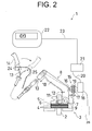
- the ON/OFF signal of the switch 15 may be outputted not only to the indication controller 21 but also to a traveling controller 26 for controlling traveling of the vehicle as shown in FIG. 2.
- the traveling controller 26 performs control such as stopping drive of the vehicle or limiting vehicle speed even when an accelerator is operated. Thus, trouble such as seizure of the parking brake 3 is prevented.
- the signal indicating the state of the switch 15 is outputted to the traveling controller 26 directly as shown in FIG. 2, but alternatively via the indication controller 21.
- the switch 15 switches to OFF when the contactor 16 is pressed by the lever body 10 and to ON when the pressing of the contactor 16 is released.
- the switch is not limited to this type but may operate in the reversed manner, that is, the switch may switch to ON when the contactor 16 is pressed and to OFF when the pressing is released.
- the other part or element other than the lever body 10 may be contactable with the contactor 16 to make the switch 15 switch to ON or OFF.
- the switch 15 switches to OFF by pressing the contactor 16 for a certain stroke.
- the switch is not limited to this type.
- the contactor is immovable and fixed, and the lever body 10 is made of an electric conductor. When the contactor and the lever body 10 contact with each other, an electricity-conducting signal is outputted to the indication controller 21.
- the position adjustment mechanism of the switch 15 is not limited to the combination of the thread of the contactor support 17 and the disc nuts 19.
- the position where the switch housing 18, not the contactor support 17, is fixed is adjusted to adjust the position of the contactor 16.
- the parking brake 3 may be changed from the wet type multi-disc parking brake into a dry type or a single-disc type.
- the above parking-brake-operation indicator is applicable to vehicles including industrial vehicles other than forklift trucks.
- a parking-brake-operation indicator includes a lever having a pressing portion for pressing a brake disc of a parking brake to press contact the brake disc, a cable operable to draw the lever, a brake-operation tool connected to the cable, a switch for detecting a position of the lever and an indicating means for indicating operation of the parking brake.
Landscapes
- Engineering & Computer Science (AREA)
- Mechanical Engineering (AREA)
- Transportation (AREA)
- General Engineering & Computer Science (AREA)
- Valves And Accessory Devices For Braking Systems (AREA)
- Braking Arrangements (AREA)
- Braking Elements And Transmission Devices (AREA)
- Regulating Braking Force (AREA)
Abstract
Description
- The present invention relates to a parking-brake-operation indicator for a parking brake that performs braking operation through a cable by manually operating a brake-operation tool of a vehicle. The present invention also relates to a method of adjusting a parking brake in a vehicle having such operation indicator.
-
Japanese Patent Application Publication No. 60-25841 -
Japanese Patent Application Publication No. 60-25841 -
Japanese Utility Model Application Publication No. 61-85565 -
Japanese Utility Model Application Publication No. 61-85565 - In the above parking brakes, the tension of the cable that connects the brake-operation tool to the parking brake (or the braking portion) may be adjusted in order to adjust the braking force of the parking brake or the operating force of the brake-operation tool.
- However, the cable may be excessively tightened depending on the adjustment of the cable tension, which causes narrow clearances between the brake discs of the parking brake. A mechanism for adjusting the cable tension is often located at a distance from the brake discs. Thus, the cable tends to be easily excessively tightened. When the brake discs are not in contact with each other but the clearances therebetween is narrow, drag torque of the parking brake becomes large due to oil viscosity, especially in a wet type multi-disc brake.
- In this regard, the braking-force sensor of
Japanese Patent Application Publication No. 60-25841 Japanese Utility Model Application Publication No. 61-85565 - According to the present invention, a parking-brake-operation indicator includes a lever having a pressing portion for pressing a brake disc of a parking brake to press contact the brake disc, a cable operable to draw the lever, a brake-operation tool connected to the cable, a switch for detecting a position of the lever and an indicating means for indicating operation of the parking brake.
- The present invention also provides a method of adjusting a parking brake in a vehicle that includes a lever having a pressing portion for pressing a brake disc of a parking brake to press contact the brake disc, a spring for urging the lever in a brake-release direction which causes braking of the parking brake to be released, a cable operable to draw the lever and a brake-operation tool connected to the cable. The method includes the steps of providing a switch for detecting a position of the lever to the vehicle; providing an indicating means for indicating state of the switch to the vehicle; adjusting tension of the cable with the brake-operation tool located in its brake position; and confirming that the lever is located in its brake-release position with the brake-operation tool located in its brake-release position.
- Other aspects and advantages of the invention will become apparent from the following description, taken in conjunction with the accompanying drawings, illustrating by way of example the principles of the invention.
- The features of the present invention that are believed to be novel are set forth with particularity in the appended claims. The invention together with objects and advantages thereof, may best be understood by reference to the following description of the presently preferred embodiments together with the accompanying drawings in which:
- FIG. 1 is a schematic view of a parking-brake-operation indicator according to a preferred embodiment of the present invention; and
- FIG. 2 is a schematic view of a parking-brake-operation indicator according to an alternative embodiment of the present invention.
- The following will describe a preferred embodiment. FIG. 1 is a schematic view of a parking-brake-operation indicator according to the preferred embodiment of the present invention.
- FIG. 1 illustrates the parking-brake-operation indicator 1 provided in a forklift truck as a vehicle. The forklift truck includes a parking brake 3 for braking a member (a
drive shaft 2 in the preferred embodiment) constituting a driving-force-transmission path from an engine (not shown) to wheels (not shown). - The parking brake 3 has a
brake housing 5 that partially covers thedrive shaft 2 that is rotatably supported at the bottom surface of the forklift truck.Brake discs 4 that are engaged with thedrive shaft 2 so as to axially move relative to and so as not to rotate with thedrive shaft 2 andbrake discs 4 that are engaged with thebrake housing 5 so as to axially move relative to and so as not to rotate with thebrake housing 5 are alternately arranged in thebrake housing 5. Thebrake housing 5 is filled with lubricating oil, thus the parking brake 3 being formed as a wet type. - A
pressing plate 6 is disposed on one side (or an upper side in FIG. 1) of the stackedbrake discs 4. Asupport 7 is located adjacently to thepressing plate 6 for pivotally supporting alever 8. Thesupport 7 is made of a plate having a bent portion at its appropriate portion. Thelever 8 has abase 9 that is rotatably supported by thesupport 7, alever body 10 that projects from thebase 9 and a fork (or a pressing portion) 11 that projects from thebase 9 and whose distal end is located adjacently to thepressing plate 6. - A return spring (or an urging spring) 12 is disposed adjacently to the
base 9. Thereturn spring 12 is typically a coil spring that is hitched at one end to thelever body 10 and at the other end to the bent portion of thesupport 7. Thus, an urging force is constantly applied to the lever body 10 (the lever 8) in a direction that causes thefork 11 not to press thebrake discs 4. - A
control cable 13 is connected at one end to the distal end of thelever body 10. Thecontrol cable 13 passes through inside aninstrumental panel 25 that is provided in front of the operator's seat of the forklift truck. Thecontrol cable 13 is connected at the other end to a parking brake lever (or a brake-operation tool) 14 that is located adjacently to the operator's seat. - The
parking brake lever 14 is of a toggle type that is pivotally moveable between a brake-release position and a brake position. A length adjuster 24 is provided on the part of thecontrol cable 13 that is located inside theinstrumental panel 25 adjacently to the connection of thecontrol cable 13 to theparking brake lever 14. The length of thecontrol cable 13 is adjustable by the length adjuster 24. The structure of the length adjuster 24 is various and may be a combination of bolt and nut. - In the preferred embodiment, a
switch 15 is provided as a sensor for detecting the position (or a brake-release position) of thelever body 10 of thelever 8 that is indicated by the solid line in FIG. 1. Theswitch 15 has acontactor 16 that is contactable with thelever body 10, atubular contactor support 17 that supports thecontactor 16 so that thecontactor 16 is movable for a certain small stroke and aswitch housing 18 that accommodates therein a switch circuit that switches between ON and OFF according to the position of thecontactor 16. - An external thread is formed on the outer circumferential surface of the
contactor support 17. Twodisc nuts 19 are screwed on the external thread of thecontactor support 17. Thedisc nuts 19 respectively have flanges between which the bent portion of thesupport 7 is sandwiched thereby to fix thecontactor support 17 to thesupport 7. The position where thecontactor support 17 is fixed to thesupport 7 or the position of theswitch 15 is adjusted in the axial direction of thecontactor support 17 by appropriately rotating thedisc nuts 19 on thecontactor support 17. - An output-
signal cable 20 is drawn from theswitch housing 18 of theswitch 15 and electrically connected to anindication controller 21. Theindication controller 21 is of a microcomputer type having a central processing unit (CPU), a read-only memory (ROM), a random access memory (RAM) and the like. Theindication controller 21 is connected through asignal cable 23 to a meter display (or an indicating means) 22 that is disposed adjacently to the operator's seat. - When the
switch 15 detects that thelever 8 is located in the position indicated by the solid line in FIG. 1 and switches to OFF, theindication controller 21 controls a "P" lamp (or a warning lamp) of themeter display 22 to be turned off. On the other hand, when thelever 8 is pivoted from the solid-line position anticlockwise as indicated by the arrow in FIG. 1 and theswitch 5 detects this and switches to ON, theindication controller 21 controls the "P" lamp of themeter display 22 to be turned on. - When the
parking brake lever 14 is located in its brake-release position as indicated by the solid line in FIG. 1, thelever 8 is pivoted by the urging force of thereturn spring 12 in a brake-release direction which causes braking of the parking brake 3 to be released or clockwise in FIG. 1 so that thelever body 10 contacts with and presses thecontactor 16 of theswitch 15. Thus, thecontactor 16 is pressed to its stroke end as indicated by the solid line in FIG. 1. In other words, thecontactor 16 at its solid-line position functions as a stopper to prevent thelever 8 from pivoting further in the brake-release direction. - In the brake-release state of the parking brake 3, the
fork 11 of thelever 8 does not press thebrake discs 4 through thepressing plate 6. Thus, there are clearances between thebrake discs 4 having appropriate intervals, with the result that thedrive shaft 2 is not dragged by thebrake discs 4 and hence is smoothly rotated. Theswitch 15 senses that thecontactor 16 is pressed and switches to OFF. Theindication controller 21 detects this and turn off the "P" lamp of themeter display 22. Therefore, an operator at the operator's seat notices that the parking brake 3 is not operated by confirming that the "P" lamp is turned off. - During a stop of the vehicle, the operator puts his or her hand on the
parking brake lever 14 and pulls it in the direction of the arrow in FIG. 1. Accordingly, thelever body 10 of thelever 8 is drawn through thecontrol cable 13 and thelever 8 is pivoted on thebase 9 anticlockwise or in the direction of the arrow in FIG. 1. Thelever body 10 moves away from thecontactor 16 of theswitch 15 and thefork 11 presses thebrake discs 4 through thepressing plate 6. Thus, the clearances between thebrake discs 4 disappear and thebrake discs 4 are brought into press contact with each other, thereby providing a friction braking force to thedrive shaft 2. In this state, theparking brake lever 14 is locked by an appropriate lock mechanism, so that the vehicle is braked so as not to move despite the intention of the operator. - In the brake state of the parking brake 3, the pressed
contactor 16 is released and moved by a return spring (not shown) leftward in FIG. 1 from the pressed position so that theswitch 15 switches to ON. Theindication controller 21 detects this and turns on the "P" lamp of themeter display 22. Therefore, it is indicated to the operator at the operator's seat that the parking brake 3 is operated. - The following will describe process for adjusting the operating force of the
parking brake lever 14 and the braking force of the parking brake 3 in the above structure. The adjustment is carried out by accessing to the inside of theinstrumental panel 25 and screwing the length adjuster 24 onto thecontrol cable 13. - More specifically, the
parking brake lever 14 is inclined to its brake position indicated by the chain double-dashed line in FIG. 1. In this state, the length adjuster 24 is screwed onto thecontrol cable 13 to adjust the tension of thecontrol cable 13 so that a desired braking force at thebrake discs 4 is obtained. - When the braking force of the parking brake 3 is desired to be increased because the vehicle is often used on slopes, the length adjuster 24 may be excessively screwed onto the
control cable 13. If so, thelever 8 may be still dragged by thecontrol cable 13 in the brake direction even when theparking brake lever 14 is returned to its brake-release position. Thus, the clearances between thebrake discs 4 are excessively small and hence drag torque becomes large. - In this regard, in this adjustment process, the
parking brake lever 14 is returned to its brake-release position and it is confirmed that the "P" lamp of themeter display 22 is turned off after the above screwing work. If the "P" lamp is not turned off after theparking brake lever 14 is returned to its brake-release position, this means that thelever body 10 is separated from theswitch 15 due to the excessive tension of thecontrol cable 13, namely, that thelever 8 fails to be returned to its brake-release position thereby to make the clearances between thebrake discs 4 narrow. In this case, the length adjuster 24 is readjusted so that the excessive tension of thecontrol cable 13 is released and it is reconfirmed whether the "P" lamp is turned off with theparking brake lever 14 located in its brake-release position. By so doing, the braking force of the parking brake is appropriately adjusted while the appropriate clearances between thebrake discs 4 are ensured in the brake-release state of the parking brake 3. - As mentioned above, the parking-brake-operation indicator 1 of the preferred embodiment includes the
lever 8 having thefork 11 for pressing thebrake discs 4 of the parking brake 3 to press contact thebrake discs 4, thecontrol cable 13 operable to drag thelever 8, theparking brake lever 14 connected to thecontrol cable 13, theswitch 15 for detecting the position of thelever 8 and themeter display 22 for indicating the operation of the parking brake 3 according to the state of theswitch 15. - Forgetting to release the parking brake 3 is indicated and the excessively narrow clearances between the
brake discs 4 is known. Therefore, drag torque is prevented from becoming large by driving the vehicle without knowing that the clearances between thebrake discs 4 are excessively narrow. - The parking-brake-operation indicator 1 of the preferred embodiment includes the
return spring 12 for urging thelever 8 in the brake-release direction, and theswitch 15 is configured to restrict the movement of thelever 8 in the brake-release direction by thecontactor 16 in a state of contacting with thelever 8. - Therefore, one end of the pivot stroke of the
lever 8 is restricted by theswitch 15. Thus, a particular restricting element need not be provided and the structure is made simpler. The one end of the pivot stroke of thelever 8, namely, the brake-release position of thelever 8 indicated by the solid line in FIG. 1 is certainly detected by theswitch 15. - In the preferred embodiment, the position of the contactor 16 (or the switch 15) is adjusted by rotating the
disc nuts 19, thereby adjusting the brake-release position of thelever 8. - Therefore, the brake-release position of the
lever 8 is adjusted through a simple structure. It is considered that the adjustment of the brake-release position of thelever 8 is carried out just before shipment of the vehicle or depending on abrasion of thebrake discs 4. - In the preferred embodiment, the parking brake is adjusted as follows. With the
parking brake lever 14 inclined in its brake position indicated by the chain double-dashed line in FIG. 1, the tension of thecontrol cable 13 is adjusted. Then, theparking brake lever 14 is inclined to its brake-release position indicated by the solid line in FIG. 1 and it is confirmed that the "P" lamp of themeter display 22 is turned off to ensure that thelever 8 is located in its brake-release position indicated by the solid line in FIG. 1. - Therefore, the press contact of the
brake discs 4, namely, the braking force of the parking brake 3 is appropriately adjusted by adjusting the tension of thecontrol cable 13 with theparking brake lever 14 located in its brake position. Meanwhile, theparking brake lever 14 is inclined to its brake-release position and the "P" lamp of themeter display 22 is confirmed, thereby certainly preventing the excessively narrow clearances between thebrake discs 4 due to the excessive tension of thecontrol cable 13. Themeter display 22 of the preferred embodiment is located adjacently to theinstrumental panel 25. Thus, the length of the clearances between thebrake discs 4 is easily confirmed by themeter display 22 in comparison with the case of actually looking at the inside of thebrake housing 5 located at the bottom surface of the forklift truck. - Although the preferred embodiment is described above, it is merely one example and the present invention is modified as exemplified below.
- As the indicating means, the shape of the warning lamp of the
meter display 22 is not limited to that as shown in FIG. 1 but may have an arbitrary shape. Instead of or in addition to the meter display 22 (or the warning lamp) optically indicating, a buzzer may be used for indicating the operation of the parking brake 3 with a sound. The brake-operation tool is not limited to theparking brake lever 14 but a pedal type tool may be used. - The ON/OFF signal of the
switch 15 may be outputted not only to theindication controller 21 but also to a travelingcontroller 26 for controlling traveling of the vehicle as shown in FIG. 2. In this case, when theswitch 15 is in ON state (the parking brake 3 performs braking or the clearances between thebrake discs 4 are narrow), the travelingcontroller 26 performs control such as stopping drive of the vehicle or limiting vehicle speed even when an accelerator is operated. Thus, trouble such as seizure of the parking brake 3 is prevented. The signal indicating the state of theswitch 15 is outputted to the travelingcontroller 26 directly as shown in FIG. 2, but alternatively via theindication controller 21. - In the preferred embodiment, the
switch 15 switches to OFF when thecontactor 16 is pressed by thelever body 10 and to ON when the pressing of thecontactor 16 is released. However, the switch is not limited to this type but may operate in the reversed manner, that is, the switch may switch to ON when thecontactor 16 is pressed and to OFF when the pressing is released. The other part or element other than thelever body 10 may be contactable with thecontactor 16 to make theswitch 15 switch to ON or OFF. - In the preferred embodiment, the
switch 15 switches to OFF by pressing thecontactor 16 for a certain stroke. However, the switch is not limited to this type. For example, the contactor is immovable and fixed, and thelever body 10 is made of an electric conductor. When the contactor and thelever body 10 contact with each other, an electricity-conducting signal is outputted to theindication controller 21. - The position adjustment mechanism of the
switch 15 is not limited to the combination of the thread of thecontactor support 17 and the disc nuts 19. For example, the position where theswitch housing 18, not thecontactor support 17, is fixed is adjusted to adjust the position of thecontactor 16. - The parking brake 3 may be changed from the wet type multi-disc parking brake into a dry type or a single-disc type. The above parking-brake-operation indicator is applicable to vehicles including industrial vehicles other than forklift trucks.
- Therefore, the present examples and embodiments are to be considered as illustrative and not restrictive, and the invention is not to be limited to the details given herein but may be modified within the scope of the appended claims.
- A parking-brake-operation indicator includes a lever having a pressing portion for pressing a brake disc of a parking brake to press contact the brake disc, a cable operable to draw the lever, a brake-operation tool connected to the cable, a switch for detecting a position of the lever and an indicating means for indicating operation of the parking brake.
Claims (10)
- A parking-brake-operation indicator comprising:a lever having a pressing portion for pressing a brake disc of a parking brake to press contact the brake disc;a cable operable to draw the lever;a brake-operation tool connected to the cable;a switch for detecting a position of the lever; andan indicating means for indicating operation of the parking brake.
- The parking-brake-operation indicator according to claim 1, further comprising a spring for urging the lever in a brake-release direction which causes braking of the parking brake to be released, the switch being configured to restrict movement of the lever in the brake-release direction in a state of contacting with the lever.
- The parking-brake-operation indicator according to claim 2, wherein the switch includes a contactor contactable with the lever.
- The parking-brake-operation indicator according to any one of claims 2 and 3, wherein the switch is configured to adjust its position so that a brake-release position of the lever is adjusted.
- The parking-brake-operation indicator according to claim 4, wherein the switch includes a tubular contactor support which has an external thread formed on its outer circumferential surface, two disc nuts being screwed on the external thread of the contactor support.
- The parking-brake-operation indicator according to claim 5, further comprising a support for supporting the lever, the support having a bent portion which is sandwiched between the disc nuts so that the contactor support is fixed to the support.
- The parking-brake-operation indicator according to any one of claims 1 through 6, wherein the switch is configured to output a signal to a controller that controls traveling of a vehicle.
- The parking-brake-operation indicator according to any one of claims 1 through 7, wherein the lever has a lever body contactable with the switch, the pressing portion projecting from the lever body.
- The parking-brake-operation indicator according to any one of claims 1 through 8, further comprising a length adjuster provided to the cable adjacently to a connection of the cable to the brake-operation tool for adjusting a length of the cable.
- A method of adjusting a parking brake in a vehicle that includes a lever having a pressing portion for pressing a brake disc of a parking brake to press contact the brake disc, a spring for urging the lever in a brake-release direction which causes braking of the parking brake to be released, a cable operable to draw the lever and a brake-operation tool connected to the cable, characterized by:providing a switch for detecting a position of the lever to the vehicle;providing an indicating means for indicating state of the switch to the vehicle;adjusting tension of the cable with the brake-operation tool located in its brake position; andconfirming that the lever is located in its brake-release position with the brake-operation tool located in its brake-release position.
Applications Claiming Priority (1)
| Application Number | Priority Date | Filing Date | Title |
|---|---|---|---|
| JP2005343018A JP4581980B2 (en) | 2005-11-29 | 2005-11-29 | Parking brake operation notification device and parking brake adjustment method |
Publications (3)
| Publication Number | Publication Date |
|---|---|
| EP1790545A2 true EP1790545A2 (en) | 2007-05-30 |
| EP1790545A3 EP1790545A3 (en) | 2008-12-10 |
| EP1790545B1 EP1790545B1 (en) | 2010-04-14 |
Family
ID=37776418
Family Applications (1)
| Application Number | Title | Priority Date | Filing Date |
|---|---|---|---|
| EP06124938A Not-in-force EP1790545B1 (en) | 2005-11-29 | 2006-11-28 | Parking-brake-operation indicator and method of adjusting parking brake |
Country Status (4)
| Country | Link |
|---|---|
| US (1) | US8117941B2 (en) |
| EP (1) | EP1790545B1 (en) |
| JP (1) | JP4581980B2 (en) |
| DE (1) | DE602006013578D1 (en) |
Families Citing this family (7)
| Publication number | Priority date | Publication date | Assignee | Title |
|---|---|---|---|---|
| SE535038C2 (en) * | 2009-11-20 | 2012-03-20 | Faiveley Transport Nordic Ab | Parking Indicator System |
| US9327698B2 (en) * | 2012-04-27 | 2016-05-03 | Deere & Company | Tractor park brake force sensing system |
| US9266513B2 (en) * | 2014-03-21 | 2016-02-23 | Caterpillar Inc. | Front park brake protection controls |
| KR101655534B1 (en) * | 2014-09-22 | 2016-09-07 | 현대자동차주식회사 | Tension control radio system for hand parking brake |
| US10001159B2 (en) * | 2016-07-22 | 2018-06-19 | Goodrich Corporation | Park brake system adjustment tool |
| RU2744259C1 (en) * | 2018-11-08 | 2021-03-04 | Евгений Федорович Скляр | Method for beginning movement of vehicle on rise |
| JP7428115B2 (en) | 2020-11-24 | 2024-02-06 | 株式会社豊田自動織機 | Parking brake for industrial vehicles |
Citations (4)
| Publication number | Priority date | Publication date | Assignee | Title |
|---|---|---|---|---|
| GB1311088A (en) | 1969-11-07 | 1973-03-21 | Girling Ltd | Indicating means for internal shoe drum brakes |
| JPS6025841A (en) | 1983-07-21 | 1985-02-08 | Toyoda Gosei Co Ltd | In-action indicating device of parking brake |
| JPS6185565U (en) | 1984-11-13 | 1986-06-05 | ||
| GB2333335A (en) | 1998-01-20 | 1999-07-21 | Lansing Linde Ltd | Brake assembly for a vehicle |
Family Cites Families (14)
| Publication number | Priority date | Publication date | Assignee | Title |
|---|---|---|---|---|
| US3542159A (en) * | 1969-01-06 | 1970-11-24 | Bendix Corp | Caliper type disc brake including pivoted sections |
| CS269973B2 (en) | 1984-09-28 | 1990-05-14 | Kurt Hierzenberger | Internal combustion engine |
| JPS61229651A (en) * | 1985-04-04 | 1986-10-13 | Touyoushiya:Kk | Parking brake |
| JPH01109630U (en) * | 1988-01-18 | 1989-07-25 | ||
| JPH062848Y2 (en) * | 1988-07-13 | 1994-01-26 | リズム自動車部品製造株式会社 | Parking brake device |
| DE4017857A1 (en) * | 1990-06-02 | 1991-12-05 | Bayerische Motoren Werke Ag | Parking brake with torque-dependent release for vehicle - is operated by opening of switch when lever of brake armature plate is rotated to sufficient extent |
| GB2264350B (en) * | 1992-02-19 | 1995-01-18 | Lansing Linde Ltd | Handbrake operating mechanisms for industrial trucks |
| US5531136A (en) * | 1994-10-03 | 1996-07-02 | Tyler; Stanley R. | Brake operating mechanism |
| JPH1029510A (en) * | 1996-07-12 | 1998-02-03 | Jidosha Kiki Co Ltd | Brake |
| JP3257444B2 (en) * | 1997-03-14 | 2002-02-18 | 三菱自動車工業株式会社 | Parking brake wire connection structure |
| US6166631A (en) * | 1998-06-04 | 2000-12-26 | Ford Global Technologies, Inc. | Method and apparatus for alerting a vehicle driver of an operating condition |
| JP2001225783A (en) * | 2000-02-17 | 2001-08-21 | Nissin Kogyo Co Ltd | Bar handle vehicle brake device and method of reporting wire cable tension used in the brake device |
| JP2001310713A (en) * | 2000-04-27 | 2001-11-06 | Toyota Motor Corp | Vehicle stop detection device |
| KR100387801B1 (en) * | 2000-12-21 | 2003-06-18 | 현대자동차주식회사 | Parking brake system |
-
2005
- 2005-11-29 JP JP2005343018A patent/JP4581980B2/en not_active Expired - Fee Related
-
2006
- 2006-11-28 DE DE602006013578T patent/DE602006013578D1/en active Active
- 2006-11-28 US US11/563,987 patent/US8117941B2/en not_active Expired - Fee Related
- 2006-11-28 EP EP06124938A patent/EP1790545B1/en not_active Not-in-force
Patent Citations (4)
| Publication number | Priority date | Publication date | Assignee | Title |
|---|---|---|---|---|
| GB1311088A (en) | 1969-11-07 | 1973-03-21 | Girling Ltd | Indicating means for internal shoe drum brakes |
| JPS6025841A (en) | 1983-07-21 | 1985-02-08 | Toyoda Gosei Co Ltd | In-action indicating device of parking brake |
| JPS6185565U (en) | 1984-11-13 | 1986-06-05 | ||
| GB2333335A (en) | 1998-01-20 | 1999-07-21 | Lansing Linde Ltd | Brake assembly for a vehicle |
Also Published As
| Publication number | Publication date |
|---|---|
| EP1790545A3 (en) | 2008-12-10 |
| EP1790545B1 (en) | 2010-04-14 |
| JP4581980B2 (en) | 2010-11-17 |
| DE602006013578D1 (en) | 2010-05-27 |
| US8117941B2 (en) | 2012-02-21 |
| JP2007145202A (en) | 2007-06-14 |
| US20070151401A1 (en) | 2007-07-05 |
Similar Documents
| Publication | Publication Date | Title |
|---|---|---|
| KR101981479B1 (en) | Method and apparatus for detecting fault of electronic parking brake | |
| US5417624A (en) | Actuating means for a motor vehicle locking brake | |
| CN111699119B (en) | Electric brake and control device | |
| US20090183958A1 (en) | Brake apparatus | |
| CN101062682A (en) | Braking method of automotive disc brake and monitoring disc brake | |
| US7374026B2 (en) | Parking brake assembly | |
| JP2005263074A (en) | Brake device for vehicle | |
| EP0586598B1 (en) | Cable operated electromechanical brake and system therefor | |
| US8117941B2 (en) | Parking-brake-operation indicator and method of adjusting parking brake | |
| JP7384135B2 (en) | Automatic braking devices for industrial vehicles and industrial vehicles | |
| US20060197374A1 (en) | Motor vehicle electric park brake system and haptic resistance actuator for same | |
| US20020185340A1 (en) | Electronic controlled brake device | |
| JP4556153B2 (en) | Electric disc brake | |
| JP3708011B2 (en) | Control device for vehicle brake | |
| US20030141158A1 (en) | Motor vehicle braking device | |
| EP2660114B1 (en) | Tractor park brake force sensing system | |
| US5992945A (en) | Hydraulic brake force regulating system | |
| US7490702B1 (en) | Parking and emergency brake actuator for a drum-in-hat disc brake assembly | |
| KR20030046973A (en) | Automotive brake system for controlling brake pedal pressure | |
| KR100489054B1 (en) | emergency break system of vehicle | |
| JP2008168785A (en) | Brake control device | |
| JPH08327480A (en) | Braking device abnormality detection device | |
| KR100207221B1 (en) | Brake full stroke locking system of vehicle | |
| KR100458190B1 (en) | brake apparatus for automobile | |
| JP2003002182A (en) | Lift truck |
Legal Events
| Date | Code | Title | Description |
|---|---|---|---|
| PUAI | Public reference made under article 153(3) epc to a published international application that has entered the european phase |
Free format text: ORIGINAL CODE: 0009012 |
|
| 17P | Request for examination filed |
Effective date: 20061128 |
|
| AK | Designated contracting states |
Kind code of ref document: A2 Designated state(s): AT BE BG CH CY CZ DE DK EE ES FI FR GB GR HU IE IS IT LI LT LU LV MC NL PL PT RO SE SI SK TR |
|
| AX | Request for extension of the european patent |
Extension state: AL BA HR MK YU |
|
| PUAL | Search report despatched |
Free format text: ORIGINAL CODE: 0009013 |
|
| AK | Designated contracting states |
Kind code of ref document: A3 Designated state(s): AT BE BG CH CY CZ DE DK EE ES FI FR GB GR HU IE IS IT LI LT LU LV MC NL PL PT RO SE SI SK TR |
|
| AX | Request for extension of the european patent |
Extension state: AL BA HR MK RS |
|
| RIC1 | Information provided on ipc code assigned before grant |
Ipc: B60T 7/10 20060101ALI20081103BHEP Ipc: B60T 7/08 20060101ALI20081103BHEP Ipc: B60T 17/22 20060101AFI20070307BHEP Ipc: F16D 49/00 20060101ALI20081103BHEP |
|
| AKX | Designation fees paid |
Designated state(s): DE FR GB |
|
| GRAP | Despatch of communication of intention to grant a patent |
Free format text: ORIGINAL CODE: EPIDOSNIGR1 |
|
| GRAS | Grant fee paid |
Free format text: ORIGINAL CODE: EPIDOSNIGR3 |
|
| GRAA | (expected) grant |
Free format text: ORIGINAL CODE: 0009210 |
|
| AK | Designated contracting states |
Kind code of ref document: B1 Designated state(s): DE FR GB |
|
| REG | Reference to a national code |
Ref country code: GB Ref legal event code: FG4D |
|
| REF | Corresponds to: |
Ref document number: 602006013578 Country of ref document: DE Date of ref document: 20100527 Kind code of ref document: P |
|
| PLBE | No opposition filed within time limit |
Free format text: ORIGINAL CODE: 0009261 |
|
| STAA | Information on the status of an ep patent application or granted ep patent |
Free format text: STATUS: NO OPPOSITION FILED WITHIN TIME LIMIT |
|
| 26N | No opposition filed |
Effective date: 20110117 |
|
| REG | Reference to a national code |
Ref country code: FR Ref legal event code: PLFP Year of fee payment: 10 |
|
| PGFP | Annual fee paid to national office [announced via postgrant information from national office to epo] |
Ref country code: DE Payment date: 20151125 Year of fee payment: 10 Ref country code: GB Payment date: 20151125 Year of fee payment: 10 |
|
| PGFP | Annual fee paid to national office [announced via postgrant information from national office to epo] |
Ref country code: FR Payment date: 20151008 Year of fee payment: 10 |
|
| REG | Reference to a national code |
Ref country code: DE Ref legal event code: R119 Ref document number: 602006013578 Country of ref document: DE |
|
| GBPC | Gb: european patent ceased through non-payment of renewal fee |
Effective date: 20161128 |
|
| REG | Reference to a national code |
Ref country code: FR Ref legal event code: ST Effective date: 20170731 |
|
| PG25 | Lapsed in a contracting state [announced via postgrant information from national office to epo] |
Ref country code: FR Free format text: LAPSE BECAUSE OF NON-PAYMENT OF DUE FEES Effective date: 20161130 |
|
| PG25 | Lapsed in a contracting state [announced via postgrant information from national office to epo] |
Ref country code: DE Free format text: LAPSE BECAUSE OF NON-PAYMENT OF DUE FEES Effective date: 20170601 Ref country code: GB Free format text: LAPSE BECAUSE OF NON-PAYMENT OF DUE FEES Effective date: 20161128 |