EP1790250A2 - Self-supporting shelf for a cabinet, in particular a refrigerator - Google Patents
Self-supporting shelf for a cabinet, in particular a refrigerator Download PDFInfo
- Publication number
- EP1790250A2 EP1790250A2 EP06122218A EP06122218A EP1790250A2 EP 1790250 A2 EP1790250 A2 EP 1790250A2 EP 06122218 A EP06122218 A EP 06122218A EP 06122218 A EP06122218 A EP 06122218A EP 1790250 A2 EP1790250 A2 EP 1790250A2
- Authority
- EP
- European Patent Office
- Prior art keywords
- shelf
- cavity
- refrigerator
- walls
- cabinet
- Prior art date
- Legal status (The legal status is an assumption and is not a legal conclusion. Google has not performed a legal analysis and makes no representation as to the accuracy of the status listed.)
- Withdrawn
Links
Images


Classifications
-
- F—MECHANICAL ENGINEERING; LIGHTING; HEATING; WEAPONS; BLASTING
- F25—REFRIGERATION OR COOLING; COMBINED HEATING AND REFRIGERATION SYSTEMS; HEAT PUMP SYSTEMS; MANUFACTURE OR STORAGE OF ICE; LIQUEFACTION SOLIDIFICATION OF GASES
- F25D—REFRIGERATORS; COLD ROOMS; ICE-BOXES; COOLING OR FREEZING APPARATUS NOT OTHERWISE PROVIDED FOR
- F25D25/00—Charging, supporting, and discharging the articles to be cooled
- F25D25/02—Charging, supporting, and discharging the articles to be cooled by shelves
-
- A—HUMAN NECESSITIES
- A47—FURNITURE; DOMESTIC ARTICLES OR APPLIANCES; COFFEE MILLS; SPICE MILLS; SUCTION CLEANERS IN GENERAL
- A47B—TABLES; DESKS; OFFICE FURNITURE; CABINETS; DRAWERS; GENERAL DETAILS OF FURNITURE
- A47B57/00—Cabinets, racks or shelf units, characterised by features for adjusting shelves or partitions
- A47B57/06—Cabinets, racks or shelf units, characterised by features for adjusting shelves or partitions with means for adjusting the height of the shelves
- A47B57/26—Cabinets, racks or shelf units, characterised by features for adjusting shelves or partitions with means for adjusting the height of the shelves consisting of clamping means, e.g. with sliding bolts or sliding wedges
-
- A—HUMAN NECESSITIES
- A47—FURNITURE; DOMESTIC ARTICLES OR APPLIANCES; COFFEE MILLS; SPICE MILLS; SUCTION CLEANERS IN GENERAL
- A47B—TABLES; DESKS; OFFICE FURNITURE; CABINETS; DRAWERS; GENERAL DETAILS OF FURNITURE
- A47B96/00—Details of cabinets, racks or shelf units not covered by a single one of groups A47B43/00 - A47B95/00; General details of furniture
- A47B96/02—Shelves
- A47B96/025—Shelves with moving elements, e.g. movable extensions or link elements
-
- F—MECHANICAL ENGINEERING; LIGHTING; HEATING; WEAPONS; BLASTING
- F25—REFRIGERATION OR COOLING; COMBINED HEATING AND REFRIGERATION SYSTEMS; HEAT PUMP SYSTEMS; MANUFACTURE OR STORAGE OF ICE; LIQUEFACTION SOLIDIFICATION OF GASES
- F25D—REFRIGERATORS; COLD ROOMS; ICE-BOXES; COOLING OR FREEZING APPARATUS NOT OTHERWISE PROVIDED FOR
- F25D23/00—General constructional features
- F25D23/06—Walls
- F25D23/065—Details
- F25D23/067—Supporting elements
-
- F—MECHANICAL ENGINEERING; LIGHTING; HEATING; WEAPONS; BLASTING
- F25—REFRIGERATION OR COOLING; COMBINED HEATING AND REFRIGERATION SYSTEMS; HEAT PUMP SYSTEMS; MANUFACTURE OR STORAGE OF ICE; LIQUEFACTION SOLIDIFICATION OF GASES
- F25D—REFRIGERATORS; COLD ROOMS; ICE-BOXES; COOLING OR FREEZING APPARATUS NOT OTHERWISE PROVIDED FOR
- F25D2325/00—Charging, supporting or discharging the articles to be cooled, not provided for in other groups of this subclass
- F25D2325/021—Shelves with several possible configurations
Definitions
- the present invention relates to a shelf for a cabinet, in particular a refrigerator, in accordance with the introduction to the main claim.
- a refrigerator is known to comprise at least one preservation cavity in which at least one shelf is positioned to support products or foods.
- This shelf usually has a flat body which is positioned on guides projecting from side walls of said cavity to assume a transverse position in the cavity and enable said products or foods to be supported.
- Said body can be defined by a grid or by a transparent or non-transparent solid element, these being of plastic (for example produced by blow or injection moulding), glass or metal.
- Said body comprises opposing sides to lie in proximity to the side walls of the refrigerator cavity and to rest on the guides present on said walls.
- refrigerators require guides integrated into the cavity structure, or supports applied to the walls of said cavity to enable at least one shelf to be disposed transversely within the cavity and enable articles to be supported.
- This requirement determines special production techniques for the refrigerator cabinet defining the cavity, which have to take into account the presence of the guides themselves. This makes it relatively difficult to produce the cabinet and makes its shape relatively complex. This is due to the need to provide several guides at different heights on the opposing side walls of the refrigerator cavity in order to allow suitable versatility in positioning the shelf within the cavity. This versatility is however limited to a finite number of possible shelf positions, with consequent constraints on the configuration and utilization of the internal space within the cabinet, in optimizing its use.
- An object of the present invention is to provide a shelf for a cabinet, in particular for a refrigerator, which is self-supporting in a cavity thereof without said cavity presenting specific means for this support.
- a second object is to provide a shelf of simple and intuitive use during its insertion into the cavity of a cabinet, in particular of a refrigerator, and its fixing into this latter.
- a third object is to provide a shelf which can be easily positioned and repositioned within a smooth-walled cavity at levels which are not predefined, to provide greater versatility in the utilisation of the interior cabinet space.
- a further object is to provide a shelf of the stated type by which the refrigerator production operations are simplified and their costs reduced.
- each shelf of the invention is indicated overall by 1 and is intended to be inserted into a cavity 2 of a cabinet 3 of a refrigerator 4.
- the cavity 2 presents opposing side walls 2A and 2B to cooperate with the shelf 1 self-supporting on them.
- the walls 2A and 2B are smooth or at least do not present elements for supporting said shelf 1.
- the shelf 1 comprises a body 7, which after its insertion and fixing into the cavity 2, becomes a flat support surface 8 for supporting foods or other products to be preserved in the refrigerator.
- the body 7 comprises at least two hinged-together cooperating portions 10, 11 to be disposed at a contained angle of greater than 180° on the surface 8 during their insertion into the cavity 2, but which become perfectly aligned (to hence define the flat surface 8) after their fixing to the walls of the cavity 2.
- the two hinged portions consist of two parts 10, 11 of the body 7 which define the said surface 8. These parts 10, 11 are hinged together and rotate about a common hinging axis: the first part 10 presents, along an edge 13 facing the corresponding edge 14 of the second part 11, a first hinge element 15 defining a substantially circular seat 20 to receive a substantially circular piece 16 defining a second hinge element 17 rigid with the second part 11 of the body 7 of the shelf 1.
- the hinge elements 15 and 17 lie along that shelf surface opposite the supporting surface 8.
- the second hinge element 17 is coupled to the first 15 in known manner, for example by snap-engagement (particularly if the body 7 is of plastic) or in any other known manner.
- the two parts 10 and 11 of the body 7 are therefore mutually movable and can be disposed at an angle to or aligned with each other.
- Each part 10, 11 is coupled along its free end 10A, 11A (to hence define a side 22 or 23 of the body 7 of the shelf 1) to a coupling member 24 for fixing said body to the corresponding wall 2A or 2B of the cavity 2 of the refrigerator 4.
- Each of these coupling and fixing members 24 cooperates by friction with the corresponding wall 2A, 2B in order to fix the shelf to this latter and support it thereon.
- each coupling and fixing member 24 is made of rubber (natural or synthetic) or other (known) material of high friction coefficient and is securely fixed to the corresponding side 22 or 23 of the part 10, 11 of the shelf 1. Fixing can be by various methods, including gluing, clinching, pressing, co-injection or the like. It can also be achieved by coupling a part 24A of this member to a seat 26 provided in the corresponding side 22 or 23 ( Figure 3).
- Each coupling and fixing member can be in the form of a compact piece ( Figures 3 and 4) or present a plurality of sucker pads (Figure 5). In all cases it comprises a part 28 to cooperate by friction with the corresponding wall 2A, 2B and to lie flat at least when this cooperation has taken place, said part 28 presenting a relatively large surface to achieve better coupling to said wall.
- the area of this surface is suitably calculated to generate a required friction on the cavity wall in relation to the thrust L exerted by the shelf 1 on the walls 2A and 2B of the cavity 2 when mounted in the cabinet 3: the larger the surface of the part 28, the greater the friction generated on the corresponding wall for an equal exerted thrust L, and hence the greater the bond between the shelf 1 and the walls 2A and 2B which enables the articles resting on said shelf to be supported.
- the shelf 1 is self-supporting on the refrigerator walls 2A and 2B, and can be installed and subsequently reposition at any non-predefined level h within the cavity 2.
- Positioning members 30, possibly integrated into the construction of the coupling and fixing members 24, can also be present on the sides 22, 23 to facilitate correct mounting of the shelf 1 by ensuring its substantial positioning planarity within the refrigerator cavity 2.
- These positioning members consist for example of fins 30 (visible in Figure 4) extending in a direction perpendicular to the individual parts 10, 11 of the shelf 1; they have a length sufficient to prevent the shelf from undergoing the behaviour required for mounted, as described hereinafter (i.e. to prevent the two half portions 10, 11 from assuming a substantially flat angle ⁇ , and hence prevent stable locking of the shelf), if the two parts 10, 11 are not individually aligned in a manner sufficiently perpendicular to the respective walls 2A and 2B.
- the positioning members enable a substantially flat mutual arrangement to be maintained, so enabling the thrust L to be generated by the shelf 1 on said walls 2A and 2B in such a manner as to generate sufficient friction for the shelf to support itself and support the articles resting on it.
- the shelf 1 is mounted in the cavity 2 in the following manner: during the insertion and positioning of the shelf, the two parts 10, 11 are rotated relative to each other so that they can be easily inserted into the refrigerator compartment ( Figure 1).
- the shelf has been inserted into the compartment 2 its two sides 22, 23 are positioned at the required height h and aligned with the walls 2A and 2B by the positioning members 30.
- a force F is applied vertically along the axis of rotation of the two parts 10, 11 of the shelf to vertically move this latter.
- the lateral force created between this shelf and the walls 2A and 2B of the refrigerator compartment 2 is such as to create sufficient friction to support the weight of the foods positioned on the shelf.
- the hinge elements To remove the shelf 1 from the interior of the refrigerator compartment 2, the hinge elements have to be released and a vertical force applied along the edges 13 and 14 of the shelf parts 10, 11 in the opposite direction to that for insertion.
- the shelf 1 comprises a monopiece 100 defining most (if not all) of the support surface 8 of the shelf; this part 100 is coupled via its edges and hinges (for example similar to those comprising the aforedescribed hinge elements 15 and 17) 101 to end parts 102 carrying the coupling and fixing members 24. These parts 102 with the members 24 define the sides 22 and 23 of the shelf 1.
- the shelf 1 is inserted into the cavity 2 by rotating the parts 102 about the hinges 101, then when the shelf is in the required position these parts are again rotated to bring them coplanar with the part 100 of the shelf 1.
- the members 24 come into contact with the walls 2A and 2B of the cavity 2 to lock the shelf 1 in the required position, in the already described manner.
- FIG. 8A, 8B, 8C, 8D show a variant of the invention.
- the shelf 1 consists of two side portions 90 and 91 which can slide in guided manner within a central body 92.
- the two slidable side portions 90 and 91 comprise the coupling and fixing members 24, formed as described in the preceding embodiments.
- These slidable portions 91, 92 also include seats 95, 96 for members for their coupling to the central body 92.
- the central body 92 includes a locking mechanism 80 for the shelf 1, composed of two levers 97, 98 connected to two shafts 97A, 98A pivoted to the central body 92 in any known manner, such as to be able to rotate about an axis 97B, 98B, by manually rotating the levers 97, 98.
- Each of the shafts 97A, 98A has a geometry such as to create at least two positions for the shelf locking mechanism 80: a first or rest position shown in Figure 8B, 8C, and a second or working position shown in Figures 8A and 8D.
- the locking device 80 with levers 97 and 98 enables a relatively low force to be applied by the operator for their manual operation, while enabling a lateral force to be generated which is sufficient for self-supporting the shelf 1.
- the two lateral portions 90 and 91 comprise T-shaped positioning members 90 which facilitate shelf alignment and prevent it from locking in the working position if the shelf is misaligned, as described for the preceding embodiments.
- the shelf 1 is mounted by inserting it in the cavity 2 while in its rest position and aligned with the walls in the same manner as the preceding embodiments.
- the shelf is then fixed to the walls by moving the levers 97, 98 of the locking mechanism 80 into their working position as described.
- the shelf is released by releasing the mechanism M by the reverse operation to that described.
- At least one stop member for example a peg
- at least one stop member can be provided for insertion into one of a plurality of close-together seats each positioned in one of the portions 10, 11 of the shelf 1, to lock the shelf 1 in its position of use.
- one (11) of the two hinged parts 10, 11 could include a support plate 1000 ( Figure 9) which becomes superposed on the adjacent part 10 when the shelf 1 is in its working position ( Figure 9B), to prevent the shelf being able to close by folding below the support level.
- the refrigerator cavity 2 can be made perfectly smooth (so facilitating its production) and each shelf located therein can be easily positioned in a plurality of non-predetermined positions on the basis of user need.
Abstract
Description
- The present invention relates to a shelf for a cabinet, in particular a refrigerator, in accordance with the introduction to the main claim.
- A refrigerator is known to comprise at least one preservation cavity in which at least one shelf is positioned to support products or foods. This shelf usually has a flat body which is positioned on guides projecting from side walls of said cavity to assume a transverse position in the cavity and enable said products or foods to be supported. Said body can be defined by a grid or by a transparent or non-transparent solid element, these being of plastic (for example produced by blow or injection moulding), glass or metal. Said body comprises opposing sides to lie in proximity to the side walls of the refrigerator cavity and to rest on the guides present on said walls.
- From the aforegoing it is apparent that known refrigerators require guides integrated into the cavity structure, or supports applied to the walls of said cavity to enable at least one shelf to be disposed transversely within the cavity and enable articles to be supported. This requirement determines special production techniques for the refrigerator cabinet defining the cavity, which have to take into account the presence of the guides themselves. This makes it relatively difficult to produce the cabinet and makes its shape relatively complex. This is due to the need to provide several guides at different heights on the opposing side walls of the refrigerator cavity in order to allow suitable versatility in positioning the shelf within the cavity. This versatility is however limited to a finite number of possible shelf positions, with consequent constraints on the configuration and utilization of the internal space within the cabinet, in optimizing its use.
- An object of the present invention is to provide a shelf for a cabinet, in particular for a refrigerator, which is self-supporting in a cavity thereof without said cavity presenting specific means for this support.
- A second object is to provide a shelf of simple and intuitive use during its insertion into the cavity of a cabinet, in particular of a refrigerator, and its fixing into this latter.
- A third object is to provide a shelf which can be easily positioned and repositioned within a smooth-walled cavity at levels which are not predefined, to provide greater versatility in the utilisation of the interior cabinet space.
- A further object is to provide a shelf of the stated type by which the refrigerator production operations are simplified and their costs reduced. These and other objects which will be apparent to the expert of the art are attained by a refrigerator shelf in accordance with the accompanying claims.
- The present invention will be more apparent from the accompanying drawings, which are provided by way of non-limiting example and in which:
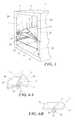
- Figure 1 is a perspective schematic view of a first shelf positioned within a refrigerator cavity, and of a second shelf shown in various stages of its positioning within the cavity;
- Figure 2 is a view similar to Figure 1 but taken from a different angle, and in which the second shelf is in a particular stage of its positioning;
- Figures 3, 4 and 5 are perspective views of different embodiments of a part of the shelf according to the invention;
- Figures 6A and 6B are perspective views of a different part of the shelf of the invention, shown in two different stages of its hinging to the refrigerator cavity;
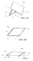
- Figure 7 is a perspective view of a first variant of the shelf according to the invention;
- Figures 8A and 8B are perspective views of a third variant of the shelf according to the invention, shown in two different working positions;
- Figures 8C and 8D are a partially sectional perspective view of a detail of the shelf locking mechanism according to the invention, shown in the two different working positions; and
- Figures 9A and 9B are perspective views of a fourth variant of the shelf according to the invention, shown in two different positioning stages.
- With reference to said figures, each shelf of the invention is indicated overall by 1 and is intended to be inserted into a
cavity 2 of a cabinet 3 of a refrigerator 4. Thecavity 2 presents opposingside walls 2A and 2B to cooperate with the shelf 1 self-supporting on them. Thewalls 2A and 2B are smooth or at least do not present elements for supporting said shelf 1. - More specifically, with reference to Figures 1 and 2, the shelf 1 comprises a body 7, which after its insertion and fixing into the
cavity 2, becomes a flat support surface 8 for supporting foods or other products to be preserved in the refrigerator. According to the invention, the body 7 comprises at least two hinged-together cooperatingportions cavity 2, but which become perfectly aligned (to hence define the flat surface 8) after their fixing to the walls of thecavity 2. - In the embodiment of Figures 1-6B, the two hinged portions consist of two
parts parts first part 10 presents, along anedge 13 facing thecorresponding edge 14 of thesecond part 11, afirst hinge element 15 defining a substantiallycircular seat 20 to receive a substantiallycircular piece 16 defining asecond hinge element 17 rigid with thesecond part 11 of the body 7 of the shelf 1. Thehinge elements - The
second hinge element 17 is coupled to the first 15 in known manner, for example by snap-engagement (particularly if the body 7 is of plastic) or in any other known manner. - The two
parts part free end side coupling member 24 for fixing said body to thecorresponding wall 2A or 2B of thecavity 2 of the refrigerator 4. - Each of these coupling and fixing
members 24 cooperates by friction with thecorresponding wall 2A, 2B in order to fix the shelf to this latter and support it thereon. - More specifically, each coupling and
fixing member 24 is made of rubber (natural or synthetic) or other (known) material of high friction coefficient and is securely fixed to thecorresponding side part part 24A of this member to aseat 26 provided in thecorresponding side 22 or 23 (Figure 3). - Each coupling and fixing member can be in the form of a compact piece (Figures 3 and 4) or present a plurality of sucker pads (Figure 5). In all cases it comprises a
part 28 to cooperate by friction with thecorresponding wall 2A, 2B and to lie flat at least when this cooperation has taken place, saidpart 28 presenting a relatively large surface to achieve better coupling to said wall. The area of this surface is suitably calculated to generate a required friction on the cavity wall in relation to the thrust L exerted by the shelf 1 on thewalls 2A and 2B of thecavity 2 when mounted in the cabinet 3: the larger the surface of thepart 28, the greater the friction generated on the corresponding wall for an equal exerted thrust L, and hence the greater the bond between the shelf 1 and thewalls 2A and 2B which enables the articles resting on said shelf to be supported. By virtue to this friction, the shelf 1 is self-supporting on therefrigerator walls 2A and 2B, and can be installed and subsequently reposition at any non-predefined level h within thecavity 2. - Positioning
members 30, possibly integrated into the construction of the coupling and fixingmembers 24, can also be present on thesides refrigerator cavity 2. - These positioning members consist for example of fins 30 (visible in Figure 4) extending in a direction perpendicular to the
individual parts half portions parts respective walls 2A and 2B. At the same time the positioning members enable a substantially flat mutual arrangement to be maintained, so enabling the thrust L to be generated by the shelf 1 on saidwalls 2A and 2B in such a manner as to generate sufficient friction for the shelf to support itself and support the articles resting on it. - The shelf 1 is mounted in the
cavity 2 in the following manner: during the insertion and positioning of the shelf, the twoparts compartment 2 its twosides walls 2A and 2B by thepositioning members 30. A force F is applied vertically along the axis of rotation of the twoparts side walls 2A and 2B, rotate about the hinging axis (see the parts indicated by 1 K, 1 H in Figure 1); by virtue of this rotational movement, with the twoshelf parts members 24 are urged outwards to increase their contact with the compartment walls. By virtue of this configuration, a small vertical force F is sufficient to create a strong lateral thrust L. - When the configuration of the shelf 1 reaches complete planarity, the lateral force created between this shelf and the
walls 2A and 2B of therefrigerator compartment 2 is such as to create sufficient friction to support the weight of the foods positioned on the shelf. - Rotation is blocked at this point by cooperation between the
edges parts - To remove the shelf 1 from the interior of the
refrigerator compartment 2, the hinge elements have to be released and a vertical force applied along theedges shelf parts - Figure 7, in which parts corresponding to those already described are indicated by the same reference numerals, shows a variant of the invention. In this, the shelf 1 comprises a monopiece 100 defining most (if not all) of the support surface 8 of the shelf; this part 100 is coupled via its edges and hinges (for example similar to those comprising the
aforedescribed hinge elements 15 and 17) 101 toend parts 102 carrying the coupling and fixingmembers 24. Theseparts 102 with themembers 24 define thesides - In the case under examination, the shelf 1 is inserted into the
cavity 2 by rotating theparts 102 about thehinges 101, then when the shelf is in the required position these parts are again rotated to bring them coplanar with the part 100 of the shelf 1. By acting in this manner themembers 24 come into contact with thewalls 2A and 2B of thecavity 2 to lock the shelf 1 in the required position, in the already described manner. - A further embodiment of the invention is described with reference to Figures 8A, 8B, 8C, 8D, in which parts corresponding to those already described are indicated by the same reference numerals, show a variant of the invention. The shelf 1 consists of two
side portions central body 92. - At their
ends slidable side portions members 24, formed as described in the preceding embodiments. Theseslidable portions seats central body 92. - The
central body 92 includes alocking mechanism 80 for the shelf 1, composed of twolevers shafts central body 92 in any known manner, such as to be able to rotate about anaxis 97B, 98B, by manually rotating thelevers - As a result of these rotations, a surface portion S1, S2 of the
shafts seats slidable parts - Each of the
shafts - When the
levers seats slidable parts shafts body 92, to enable the shelf 1 to be inserted into thecavity 2 and be then positioned for mounting, with the possible aid of the already described positioningmembers 30. - When the shelf 1 has assumed its working position, by rotating the
levers shaft shelf members 24, to fix the shelf 1 to thewalls 2A and 2B of thecavity 2 of the cabinet 3 in the manner describe in the preceding embodiments. Once the shelf 1 has been configured in its working position, by manually rotating thelevers shelves - A certain force has to be applied to the
levers seats - The locking
device 80 withlevers lateral portions positioning members 90 which facilitate shelf alignment and prevent it from locking in the working position if the shelf is misaligned, as described for the preceding embodiments. - The shelf 1 is mounted by inserting it in the
cavity 2 while in its rest position and aligned with the walls in the same manner as the preceding embodiments. The shelf is then fixed to the walls by moving thelevers locking mechanism 80 into their working position as described. The shelf is released by releasing the mechanism M by the reverse operation to that described. - Various embodiments of the invention have been described. Others can however be deduced therefrom. For example, at least one stop member (for example a peg) can be provided for insertion into one of a plurality of close-together seats each positioned in one of the
portions parts adjacent part 10 when the shelf 1 is in its working position (Figure 9B), to prevent the shelf being able to close by folding below the support level. - Another variant, not shown, comprises the combined use of coupling and fixing
members 24 of high friction coefficient with sucker elements. These variants are also to be considered as falling within the scope of the ensuing claims. - By virtue of the invention, the
refrigerator cavity 2 can be made perfectly smooth (so facilitating its production) and each shelf located therein can be easily positioned in a plurality of non-predetermined positions on the basis of user need. - Finally, although the device has been described in the embodiments in association with a refrigerator 4, it can also be applied in smooth-walled cupboards where the use of shelves is required, for example wall-mounted furniture units for kitchens and the like.
Claims (19)
- A shelf for a cabinet (3), comprising a body (7) to be disposed in at least one cavity (2) of said cabinet (3), in this latter the body (7) being positioned transversely to present a flat surface (8) intended to support products, the body (7) presenting opposing sides (22, 23) to be positioned facing corresponding side walls (2A and 2B) of said cavity (2), characterised in that the body (7) of the shelf (1) comprises at least two parts (10, 11; 100, 102; 90, 91, 92) lockable in a working position in which said body is substantially flat and its opposing sides (22, 23) cooperate with the side walls (2A and 2B) of the cavity (2), said sides (22, 23) carrying coupling means (24) to be positioned on said walls (2A and 2B) when said body (7) is in said working position so as to fix it to said walls and enable the shelf (1) to be self-supporting in said cavity (2) in a substantially flat position.
- A shelf as claimed in claim 1, characterised in that said cavity (2) is the cavity of a refrigerator (4).
- A shelf as claimed in claim 1, characterised in that said shelf (1) can be positioned at any level of the cavity (2) within the cabinet (3).
- A shelf as claimed in claim 1, characterised by comprising a positioning member (30) for said shelf (1), for its substantially flat positioning within the cavity (2).
- A shelf as claimed in claim 1, characterised in that the two parts (10, 11) are hinged, to each define a portion of the flat surface (8) intended to support the products or foods to be preserved, said parts each carrying the means (24) for coupling the shelf to the walls (2A and 2B) of the cavity (2) of the cabinet (3).
- A shelf as claimed in claims 1 and 2, characterised by comprising three hinged parts, a first part (100) defining substantially at least most of the flat surface (8) to support the products or foods to be preserved, a second part and a third part (102) being hinged to the free edges of said first part (100) and carrying the means for coupling the shelf (1) to the walls (2A and 2B) of the refrigerator cavity (2).
- A shelf as claimed in claim 1, characterised in that the hinged-together parts (10, 11; 100, 102) present corresponding hinge elements (15, 17) formed such that the adjacent edges (13, 14) of said parts (10, 11; 100, 102) become coupled together when the shelf (1) is in its working position, in which its body (7) is flat.
- A shelf as claimed in claim 6, characterised in that the hinge elements (15, 17) are positioned along that surface of the shelf (1) opposite the surface (8) which supports the products or foods to be preserved.
- A shelf as claimed in claim 6, characterised in that a first hinge element (15) defines a substantially circular seat (20) for a substantially circular part (16) of the second hinge element (17).
- A shelf as claimed in claim 1, characterised in that the coupling means are a member (24) of high friction coefficient fixed to the sides (22, 23) of the shelf (1).
- A shelf as claimed in claim 10, characterised in that the member (24) of high friction coefficient is of elastomeric material.
- A shelf as claimed in claim 10, characterised in that the member (24) of high friction coefficient presents suckers to cooperate with the corresponding wall (2A and 2B) of the refrigerator compartment.
- A shelf as claimed in claim 10, characterised in that the member (24) of high friction coefficient presents a part (28) arranged to cooperate with the corresponding wall (2A and 2B) of the cavity (2), said part (28) being flat at least at the moment of this cooperation.
- A shelf as claimed in claim 10, characterised in that the member (24) of high friction coefficient is mechanically fixed to the corresponding side (22, 23) of the shelf (1).
- A shelf as claimed in claim 10, characterised in that the member (24) of high friction coefficient is moulded onto the corresponding side (22, 23) of the shelf (1).
- A shelf as claimed in claim 10, characterised in that the member (24) of high friction coefficient is co-injection moulded with the respective side (22, 23) of the shelf (1).
- A shelf as claimed in claim 1, characterised by comprising a stop member inserted into one of a plurality of close-together seats each positioned in one of the portions (10, 11; 100, 102) of the shelf (1), to lock the shelf (1) in its position of use.
- A shelf as claimed in claim 1, characterised by comprising a stop member operated by a lever mechanism (97, 98) and arranged to lock the shelf (1) in its position of use.
- A refrigerator comprising a cabinet (3) in which at least one cavity (2) is provided to contain foods or products to be preserved, said cavity presenting opposing side walls (2A and 2B) intended to cooperate with at least one shelf (1) supporting said foods or products, said at least one shelf presenting the characteristics of claim 1, characterised in that said side walls (2A and 2B) of the refrigerator cavity (4) are not provided with support members for said at least one shelf, this latter being self-supporting within said cavity (2).
Applications Claiming Priority (1)
| Application Number | Priority Date | Filing Date | Title |
|---|---|---|---|
| ITMI20052138 ITMI20052138A1 (en) | 2005-11-09 | 2005-11-09 | SELF-SUPPORTING SHELF FOR MOBILE IN PARTICULAR FOR REFRIGERATOR |
Publications (2)
| Publication Number | Publication Date |
|---|---|
| EP1790250A2 true EP1790250A2 (en) | 2007-05-30 |
| EP1790250A3 EP1790250A3 (en) | 2011-08-03 |
Family
ID=37774943
Family Applications (1)
| Application Number | Title | Priority Date | Filing Date |
|---|---|---|---|
| EP06122218A Withdrawn EP1790250A3 (en) | 2005-11-09 | 2006-10-12 | Self-supporting shelf for a cabinet, in particular a refrigerator |
Country Status (2)
| Country | Link |
|---|---|
| EP (1) | EP1790250A3 (en) |
| IT (1) | ITMI20052138A1 (en) |
Cited By (19)
| Publication number | Priority date | Publication date | Assignee | Title |
|---|---|---|---|---|
| WO2011092117A1 (en) * | 2010-02-01 | 2011-08-04 | BSH Bosch und Siemens Hausgeräte GmbH | Separating element for a household refrigeration device |
| WO2011154432A1 (en) * | 2010-06-08 | 2011-12-15 | Arcelik Anonim Sirketi | A cooling device |
| RU2503897C2 (en) * | 2008-11-06 | 2014-01-10 | Индезит Компани С.П.А. | Cooling device |
| DE102014010340B3 (en) * | 2014-07-11 | 2015-09-24 | Faurecia Innenraum Systeme Gmbh | Department device for a storage compartment |
| WO2017036554A1 (en) * | 2015-09-04 | 2017-03-09 | Arcelik Anonim Sirketi | Height-adjustable shelf for a refrigerator |
| USD839321S1 (en) | 2015-03-17 | 2019-01-29 | Whirlpool Corporation | Refrigerator |
| US10371436B2 (en) | 2017-11-08 | 2019-08-06 | Whirlpool Corporation | Bin assembly |
| US10473383B2 (en) | 2017-09-08 | 2019-11-12 | Whirlpool Corporation | Refrigerator shelf translation system |
| US10551071B2 (en) | 2018-05-11 | 2020-02-04 | Whirlpool Corporation | Oven rack system with removable support elements |
| USD883348S1 (en) | 2015-10-09 | 2020-05-05 | Whirlpool Corporation | Refrigerator shelf |
| US10655905B2 (en) | 2017-06-13 | 2020-05-19 | Whirlpool Corporation | Flexible compartment for a refrigerator |
| US10677514B2 (en) | 2017-08-01 | 2020-06-09 | Whirlpool Corporation | Door bin with dual material and system lock |
| US10690400B2 (en) | 2017-05-11 | 2020-06-23 | Whirlpool Corporation | Household appliance comprising shelf arrangement |
| US10704825B2 (en) | 2015-03-17 | 2020-07-07 | Whirlpool Corporation | U-shaped tuck shelf |
| DE102010016591B4 (en) * | 2009-11-25 | 2020-08-20 | Paul Hettich Gmbh & Co. Kg | Drawer and divider for a drawer |
| US10808944B2 (en) | 2018-01-12 | 2020-10-20 | Whirlpool Corporation | Swinging rack |
| US10823480B2 (en) | 2017-08-01 | 2020-11-03 | Whirlpool Corporation | Air flow mechanism for compartment |
| US10823490B2 (en) | 2017-10-12 | 2020-11-03 | Whirlpool Corporation | Shelf assembly for appliance |
| US11073329B2 (en) | 2018-10-31 | 2021-07-27 | Whirlpool Corporation | Refrigerator shelving frame with snap-in sliding insert |
Citations (8)
| Publication number | Priority date | Publication date | Assignee | Title |
|---|---|---|---|---|
| US4923260A (en) * | 1989-08-29 | 1990-05-08 | White Consolidated Industries, Inc. | Refrigerator shelf construction |
| EP0401052A2 (en) * | 1989-06-02 | 1990-12-05 | Donald G. Santucci | Adjustable self supporting locker shelf and method for installing same |
| US5421646A (en) * | 1993-07-12 | 1995-06-06 | Minnesota American, Inc. | Legless locker shelf assembly |
| US5819937A (en) * | 1997-05-16 | 1998-10-13 | Walker; Kimberly K. | Bottle organizer |
| US20030117050A1 (en) * | 2001-12-20 | 2003-06-26 | Hamilton Roger E. | Refrigerator shelving assembly |
| US20030226815A1 (en) * | 2002-05-31 | 2003-12-11 | Gaunt Bruce William | Expandable shelf |
| CN2596290Y (en) * | 2002-11-29 | 2003-12-31 | 上海喜士多便利连锁有限公司 | Shelf in refreigerator |
| US20060186769A1 (en) * | 2005-02-24 | 2006-08-24 | Jerry Harris | Locker shelf |
-
2005
- 2005-11-09 IT ITMI20052138 patent/ITMI20052138A1/en unknown
-
2006
- 2006-10-12 EP EP06122218A patent/EP1790250A3/en not_active Withdrawn
Patent Citations (8)
| Publication number | Priority date | Publication date | Assignee | Title |
|---|---|---|---|---|
| EP0401052A2 (en) * | 1989-06-02 | 1990-12-05 | Donald G. Santucci | Adjustable self supporting locker shelf and method for installing same |
| US4923260A (en) * | 1989-08-29 | 1990-05-08 | White Consolidated Industries, Inc. | Refrigerator shelf construction |
| US5421646A (en) * | 1993-07-12 | 1995-06-06 | Minnesota American, Inc. | Legless locker shelf assembly |
| US5819937A (en) * | 1997-05-16 | 1998-10-13 | Walker; Kimberly K. | Bottle organizer |
| US20030117050A1 (en) * | 2001-12-20 | 2003-06-26 | Hamilton Roger E. | Refrigerator shelving assembly |
| US20030226815A1 (en) * | 2002-05-31 | 2003-12-11 | Gaunt Bruce William | Expandable shelf |
| CN2596290Y (en) * | 2002-11-29 | 2003-12-31 | 上海喜士多便利连锁有限公司 | Shelf in refreigerator |
| US20060186769A1 (en) * | 2005-02-24 | 2006-08-24 | Jerry Harris | Locker shelf |
Cited By (27)
| Publication number | Priority date | Publication date | Assignee | Title |
|---|---|---|---|---|
| RU2503897C2 (en) * | 2008-11-06 | 2014-01-10 | Индезит Компани С.П.А. | Cooling device |
| DE102010016591B4 (en) * | 2009-11-25 | 2020-08-20 | Paul Hettich Gmbh & Co. Kg | Drawer and divider for a drawer |
| WO2011092117A1 (en) * | 2010-02-01 | 2011-08-04 | BSH Bosch und Siemens Hausgeräte GmbH | Separating element for a household refrigeration device |
| WO2011154432A1 (en) * | 2010-06-08 | 2011-12-15 | Arcelik Anonim Sirketi | A cooling device |
| DE102014010340B3 (en) * | 2014-07-11 | 2015-09-24 | Faurecia Innenraum Systeme Gmbh | Department device for a storage compartment |
| US11598577B2 (en) | 2015-03-17 | 2023-03-07 | Whirlpool Corporation | U-shaped tuck shelf |
| US10704825B2 (en) | 2015-03-17 | 2020-07-07 | Whirlpool Corporation | U-shaped tuck shelf |
| USD839321S1 (en) | 2015-03-17 | 2019-01-29 | Whirlpool Corporation | Refrigerator |
| WO2017036554A1 (en) * | 2015-09-04 | 2017-03-09 | Arcelik Anonim Sirketi | Height-adjustable shelf for a refrigerator |
| USD978205S1 (en) | 2015-10-09 | 2023-02-14 | Whirlpool Corporation | Refrigerator shelf |
| USD954767S1 (en) | 2015-10-09 | 2022-06-14 | Whirlpool Corporation | Refrigerator shelf |
| USD883348S1 (en) | 2015-10-09 | 2020-05-05 | Whirlpool Corporation | Refrigerator shelf |
| USD926235S1 (en) | 2015-10-09 | 2021-07-27 | Whirlpool Corporation | Refrigerator shelf |
| US10690400B2 (en) | 2017-05-11 | 2020-06-23 | Whirlpool Corporation | Household appliance comprising shelf arrangement |
| US11371771B2 (en) | 2017-05-11 | 2022-06-28 | Whirlpool Corporation | Household appliance comprising shelf arrangement |
| US10655905B2 (en) | 2017-06-13 | 2020-05-19 | Whirlpool Corporation | Flexible compartment for a refrigerator |
| US10823480B2 (en) | 2017-08-01 | 2020-11-03 | Whirlpool Corporation | Air flow mechanism for compartment |
| US11650000B2 (en) | 2017-08-01 | 2023-05-16 | Whirlpool Corporation | Air flow mechanism for compartment |
| US10677514B2 (en) | 2017-08-01 | 2020-06-09 | Whirlpool Corporation | Door bin with dual material and system lock |
| US10473383B2 (en) | 2017-09-08 | 2019-11-12 | Whirlpool Corporation | Refrigerator shelf translation system |
| US11774169B2 (en) | 2017-10-12 | 2023-10-03 | Whirlpool Corporation | Shelf assembly for appliance |
| US10823490B2 (en) | 2017-10-12 | 2020-11-03 | Whirlpool Corporation | Shelf assembly for appliance |
| US10371436B2 (en) | 2017-11-08 | 2019-08-06 | Whirlpool Corporation | Bin assembly |
| US10808944B2 (en) | 2018-01-12 | 2020-10-20 | Whirlpool Corporation | Swinging rack |
| US11796184B2 (en) | 2018-01-12 | 2023-10-24 | Whirlpool Corporation | Oven rack assembly with rotating mounting arms |
| US10551071B2 (en) | 2018-05-11 | 2020-02-04 | Whirlpool Corporation | Oven rack system with removable support elements |
| US11073329B2 (en) | 2018-10-31 | 2021-07-27 | Whirlpool Corporation | Refrigerator shelving frame with snap-in sliding insert |
Also Published As
| Publication number | Publication date |
|---|---|
| ITMI20052138A1 (en) | 2007-05-10 |
| EP1790250A3 (en) | 2011-08-03 |
Similar Documents
| Publication | Publication Date | Title |
|---|---|---|
| EP1790250A2 (en) | Self-supporting shelf for a cabinet, in particular a refrigerator | |
| KR100854827B1 (en) | Elevation adjustment structure of shelf for refrigerator | |
| EP3546862B1 (en) | Refrigerator | |
| US7748805B2 (en) | Means for providing adjustment to bins and shelves in refrigerators | |
| US8444239B2 (en) | Offset weight supporting slide | |
| US8777341B2 (en) | Sliding shelves for refrigerators and freezers | |
| US7810890B2 (en) | Glide mechanism for roll out drawers and other items | |
| EP3015802B1 (en) | Refrigerator | |
| US6582038B2 (en) | Storage bin mounting system for a refrigerator door | |
| EP1850078A2 (en) | Ice bucket retainer for refrigerator | |
| EP2848880A2 (en) | Refrigerator and shelf assembly for a refrigerator | |
| KR20070104505A (en) | Refrigerator compartment housing vertically adjustable shelves | |
| CA2751971A1 (en) | Pivoting shelf assembly | |
| US6263808B1 (en) | Rotary stepped storage and display and method | |
| US9486078B2 (en) | Shelf assembly | |
| US7249430B2 (en) | Frameless display fixture | |
| US11229288B2 (en) | Refrigerator with a sliding shelf | |
| EP1835248A2 (en) | Internal refrigerator component for containing and supporting food and bottles | |
| CN109764623A (en) | Adjustable shelf and the refrigerator for using the adjustable shelf | |
| US20210293470A1 (en) | Refrigerator with a sliding shelf | |
| US20230175768A1 (en) | Shelf assembly for an appliance | |
| JP4458403B2 (en) | Product display case | |
| US20230144852A1 (en) | Refrigerator Shelves | |
| JP2887073B2 (en) | Article holding device | |
| CN114576895A (en) | Slide rail assembly and refrigerator |
Legal Events
| Date | Code | Title | Description |
|---|---|---|---|
| PUAI | Public reference made under article 153(3) epc to a published international application that has entered the european phase |
Free format text: ORIGINAL CODE: 0009012 |
|
| AK | Designated contracting states |
Kind code of ref document: A2 Designated state(s): AT BE BG CH CY CZ DE DK EE ES FI FR GB GR HU IE IS IT LI LT LU LV MC NL PL PT RO SE SI SK TR |
|
| AX | Request for extension of the european patent |
Extension state: AL BA HR MK YU |
|
| PUAL | Search report despatched |
Free format text: ORIGINAL CODE: 0009013 |
|
| AK | Designated contracting states |
Kind code of ref document: A3 Designated state(s): AT BE BG CH CY CZ DE DK EE ES FI FR GB GR HU IE IS IT LI LT LU LV MC NL PL PT RO SE SI SK TR |
|
| AX | Request for extension of the european patent |
Extension state: AL BA HR MK RS |
|
| AKY | No designation fees paid | ||
| REG | Reference to a national code |
Ref country code: DE Ref legal event code: R108 Effective date: 20120411 |
|
| STAA | Information on the status of an ep patent application or granted ep patent |
Free format text: STATUS: THE APPLICATION IS DEEMED TO BE WITHDRAWN |
|
| 18D | Application deemed to be withdrawn |
Effective date: 20120204 |