EP1788469A1 - Control method for moving carriage - Google Patents
Control method for moving carriage Download PDFInfo
- Publication number
- EP1788469A1 EP1788469A1 EP06767778A EP06767778A EP1788469A1 EP 1788469 A1 EP1788469 A1 EP 1788469A1 EP 06767778 A EP06767778 A EP 06767778A EP 06767778 A EP06767778 A EP 06767778A EP 1788469 A1 EP1788469 A1 EP 1788469A1
- Authority
- EP
- European Patent Office
- Prior art keywords
- tilt angle
- wheel
- angular velocity
- command value
- external force
- Prior art date
- Legal status (The legal status is an assumption and is not a legal conclusion. Google has not performed a legal analysis and makes no representation as to the accuracy of the status listed.)
- Granted
Links
Images


Classifications
-
- G—PHYSICS
- G05—CONTROLLING; REGULATING
- G05B—CONTROL OR REGULATING SYSTEMS IN GENERAL; FUNCTIONAL ELEMENTS OF SUCH SYSTEMS; MONITORING OR TESTING ARRANGEMENTS FOR SUCH SYSTEMS OR ELEMENTS
- G05B13/00—Adaptive control systems, i.e. systems automatically adjusting themselves to have a performance which is optimum according to some preassigned criterion
- G05B13/02—Adaptive control systems, i.e. systems automatically adjusting themselves to have a performance which is optimum according to some preassigned criterion electric
-
- B—PERFORMING OPERATIONS; TRANSPORTING
- B62—LAND VEHICLES FOR TRAVELLING OTHERWISE THAN ON RAILS
- B62K—CYCLES; CYCLE FRAMES; CYCLE STEERING DEVICES; RIDER-OPERATED TERMINAL CONTROLS SPECIALLY ADAPTED FOR CYCLES; CYCLE AXLE SUSPENSIONS; CYCLE SIDECARS, FORECARS, OR THE LIKE
- B62K17/00—Cycles not otherwise provided for
-
- B—PERFORMING OPERATIONS; TRANSPORTING
- B60—VEHICLES IN GENERAL
- B60L—PROPULSION OF ELECTRICALLY-PROPELLED VEHICLES; SUPPLYING ELECTRIC POWER FOR AUXILIARY EQUIPMENT OF ELECTRICALLY-PROPELLED VEHICLES; ELECTRODYNAMIC BRAKE SYSTEMS FOR VEHICLES IN GENERAL; MAGNETIC SUSPENSION OR LEVITATION FOR VEHICLES; MONITORING OPERATING VARIABLES OF ELECTRICALLY-PROPELLED VEHICLES; ELECTRIC SAFETY DEVICES FOR ELECTRICALLY-PROPELLED VEHICLES
- B60L15/00—Methods, circuits, or devices for controlling the traction-motor speed of electrically-propelled vehicles
- B60L15/20—Methods, circuits, or devices for controlling the traction-motor speed of electrically-propelled vehicles for control of the vehicle or its driving motor to achieve a desired performance, e.g. speed, torque, programmed variation of speed
-
- G—PHYSICS
- G05—CONTROLLING; REGULATING
- G05D—SYSTEMS FOR CONTROLLING OR REGULATING NON-ELECTRIC VARIABLES
- G05D1/00—Control of position, course, altitude or attitude of land, water, air or space vehicles, e.g. using automatic pilots
- G05D1/08—Control of attitude, i.e. control of roll, pitch, or yaw
- G05D1/0891—Control of attitude, i.e. control of roll, pitch, or yaw specially adapted for land vehicles
-
- B—PERFORMING OPERATIONS; TRANSPORTING
- B60—VEHICLES IN GENERAL
- B60L—PROPULSION OF ELECTRICALLY-PROPELLED VEHICLES; SUPPLYING ELECTRIC POWER FOR AUXILIARY EQUIPMENT OF ELECTRICALLY-PROPELLED VEHICLES; ELECTRODYNAMIC BRAKE SYSTEMS FOR VEHICLES IN GENERAL; MAGNETIC SUSPENSION OR LEVITATION FOR VEHICLES; MONITORING OPERATING VARIABLES OF ELECTRICALLY-PROPELLED VEHICLES; ELECTRIC SAFETY DEVICES FOR ELECTRICALLY-PROPELLED VEHICLES
- B60L2200/00—Type of vehicles
- B60L2200/28—Trailers
-
- B—PERFORMING OPERATIONS; TRANSPORTING
- B60—VEHICLES IN GENERAL
- B60L—PROPULSION OF ELECTRICALLY-PROPELLED VEHICLES; SUPPLYING ELECTRIC POWER FOR AUXILIARY EQUIPMENT OF ELECTRICALLY-PROPELLED VEHICLES; ELECTRODYNAMIC BRAKE SYSTEMS FOR VEHICLES IN GENERAL; MAGNETIC SUSPENSION OR LEVITATION FOR VEHICLES; MONITORING OPERATING VARIABLES OF ELECTRICALLY-PROPELLED VEHICLES; ELECTRIC SAFETY DEVICES FOR ELECTRICALLY-PROPELLED VEHICLES
- B60L2220/00—Electrical machine types; Structures or applications thereof
- B60L2220/40—Electrical machine applications
- B60L2220/46—Wheel motors, i.e. motor connected to only one wheel
-
- B—PERFORMING OPERATIONS; TRANSPORTING
- B60—VEHICLES IN GENERAL
- B60L—PROPULSION OF ELECTRICALLY-PROPELLED VEHICLES; SUPPLYING ELECTRIC POWER FOR AUXILIARY EQUIPMENT OF ELECTRICALLY-PROPELLED VEHICLES; ELECTRODYNAMIC BRAKE SYSTEMS FOR VEHICLES IN GENERAL; MAGNETIC SUSPENSION OR LEVITATION FOR VEHICLES; MONITORING OPERATING VARIABLES OF ELECTRICALLY-PROPELLED VEHICLES; ELECTRIC SAFETY DEVICES FOR ELECTRICALLY-PROPELLED VEHICLES
- B60L2240/00—Control parameters of input or output; Target parameters
- B60L2240/10—Vehicle control parameters
- B60L2240/14—Acceleration
- B60L2240/18—Acceleration lateral
-
- B—PERFORMING OPERATIONS; TRANSPORTING
- B60—VEHICLES IN GENERAL
- B60L—PROPULSION OF ELECTRICALLY-PROPELLED VEHICLES; SUPPLYING ELECTRIC POWER FOR AUXILIARY EQUIPMENT OF ELECTRICALLY-PROPELLED VEHICLES; ELECTRODYNAMIC BRAKE SYSTEMS FOR VEHICLES IN GENERAL; MAGNETIC SUSPENSION OR LEVITATION FOR VEHICLES; MONITORING OPERATING VARIABLES OF ELECTRICALLY-PROPELLED VEHICLES; ELECTRIC SAFETY DEVICES FOR ELECTRICALLY-PROPELLED VEHICLES
- B60L2240/00—Control parameters of input or output; Target parameters
- B60L2240/10—Vehicle control parameters
- B60L2240/14—Acceleration
- B60L2240/20—Acceleration angular
-
- B—PERFORMING OPERATIONS; TRANSPORTING
- B60—VEHICLES IN GENERAL
- B60L—PROPULSION OF ELECTRICALLY-PROPELLED VEHICLES; SUPPLYING ELECTRIC POWER FOR AUXILIARY EQUIPMENT OF ELECTRICALLY-PROPELLED VEHICLES; ELECTRODYNAMIC BRAKE SYSTEMS FOR VEHICLES IN GENERAL; MAGNETIC SUSPENSION OR LEVITATION FOR VEHICLES; MONITORING OPERATING VARIABLES OF ELECTRICALLY-PROPELLED VEHICLES; ELECTRIC SAFETY DEVICES FOR ELECTRICALLY-PROPELLED VEHICLES
- B60L2240/00—Control parameters of input or output; Target parameters
- B60L2240/10—Vehicle control parameters
- B60L2240/24—Steering angle
-
- B—PERFORMING OPERATIONS; TRANSPORTING
- B60—VEHICLES IN GENERAL
- B60L—PROPULSION OF ELECTRICALLY-PROPELLED VEHICLES; SUPPLYING ELECTRIC POWER FOR AUXILIARY EQUIPMENT OF ELECTRICALLY-PROPELLED VEHICLES; ELECTRODYNAMIC BRAKE SYSTEMS FOR VEHICLES IN GENERAL; MAGNETIC SUSPENSION OR LEVITATION FOR VEHICLES; MONITORING OPERATING VARIABLES OF ELECTRICALLY-PROPELLED VEHICLES; ELECTRIC SAFETY DEVICES FOR ELECTRICALLY-PROPELLED VEHICLES
- B60L2240/00—Control parameters of input or output; Target parameters
- B60L2240/40—Drive Train control parameters
- B60L2240/42—Drive Train control parameters related to electric machines
- B60L2240/423—Torque
-
- B—PERFORMING OPERATIONS; TRANSPORTING
- B60—VEHICLES IN GENERAL
- B60L—PROPULSION OF ELECTRICALLY-PROPELLED VEHICLES; SUPPLYING ELECTRIC POWER FOR AUXILIARY EQUIPMENT OF ELECTRICALLY-PROPELLED VEHICLES; ELECTRODYNAMIC BRAKE SYSTEMS FOR VEHICLES IN GENERAL; MAGNETIC SUSPENSION OR LEVITATION FOR VEHICLES; MONITORING OPERATING VARIABLES OF ELECTRICALLY-PROPELLED VEHICLES; ELECTRIC SAFETY DEVICES FOR ELECTRICALLY-PROPELLED VEHICLES
- B60L2260/00—Operating Modes
- B60L2260/20—Drive modes; Transition between modes
- B60L2260/34—Stabilising upright position of vehicles, e.g. of single axle vehicles
-
- Y—GENERAL TAGGING OF NEW TECHNOLOGICAL DEVELOPMENTS; GENERAL TAGGING OF CROSS-SECTIONAL TECHNOLOGIES SPANNING OVER SEVERAL SECTIONS OF THE IPC; TECHNICAL SUBJECTS COVERED BY FORMER USPC CROSS-REFERENCE ART COLLECTIONS [XRACs] AND DIGESTS
- Y02—TECHNOLOGIES OR APPLICATIONS FOR MITIGATION OR ADAPTATION AGAINST CLIMATE CHANGE
- Y02T—CLIMATE CHANGE MITIGATION TECHNOLOGIES RELATED TO TRANSPORTATION
- Y02T10/00—Road transport of goods or passengers
- Y02T10/60—Other road transportation technologies with climate change mitigation effect
- Y02T10/64—Electric machine technologies in electromobility
-
- Y—GENERAL TAGGING OF NEW TECHNOLOGICAL DEVELOPMENTS; GENERAL TAGGING OF CROSS-SECTIONAL TECHNOLOGIES SPANNING OVER SEVERAL SECTIONS OF THE IPC; TECHNICAL SUBJECTS COVERED BY FORMER USPC CROSS-REFERENCE ART COLLECTIONS [XRACs] AND DIGESTS
- Y02—TECHNOLOGIES OR APPLICATIONS FOR MITIGATION OR ADAPTATION AGAINST CLIMATE CHANGE
- Y02T—CLIMATE CHANGE MITIGATION TECHNOLOGIES RELATED TO TRANSPORTATION
- Y02T10/00—Road transport of goods or passengers
- Y02T10/60—Other road transportation technologies with climate change mitigation effect
- Y02T10/72—Electric energy management in electromobility
Definitions
- the present invention relates to control method of an inverted pendulum-type traveling dolly that a centroid of the body positions above a rotation axis of a wheel.
- the present invention also relates to the traveling dolly.
- a traveling dolly which has a wheel and a body supported by the wheel, a centroid of the body positioning above a rotation axis of the wheel.
- control at the dolly translation direction including the direction rectangular to the axis
- the position control and control at the dolly rotation direction including only the position control are performed.
- the traveling dolly has a control means calculating control command value to a drive means for the wheel (torque command value to a motor).
- the control means is so robust as to make the body stand invertedly stably against disturbance. Accordingly, even if the dolly located surface slopes or load is changed, the body can keep on standing stably.
- wheel angle rotation angle of the wheel relative to the body
- wheel angular velocity which is single integral of the wheel angle body tilt angle (tilt from the vertical direction)
- body tilt angular velocity which is single integral of the body tilt angle
- the body tilt angle is instable so that the dolly cannot stand invertedly stably without feedback control.
- the control input is determined so as to make all the state quantities zero.
- control at the dolly translation direction disclosed in the Japanese Patent Laid Open Gazette 2004-295430 has one input (axle torque) and two outputs (wheel angle and body tilt angle) and uses the wheel angle and the body tilt angle so as to calculate the torque command value to the motor. Accordingly, trade-off (the relation that if one of conditions is satisfied, the other condition becomes dissatisfied) exists between the two outputs, and if the disturbance applied on the dolly is large, below problems may be caused.
- the dolly slightly moves and stops at the initial position by the above-mentioned control.
- the body tilt angle and the wheel angle cannot be made zero simultaneously, whereby the oscillation centering on the initial position (the position of the dolly before applying the disturbance thereon) is difficult to be converged.
- the position of the wheel is moved widely (the wheel angle is changed widely).
- the position of the wheel must be moved widely and an operator cannot get on and off easily.
- the purpose of the present invention is to provide control method of a traveling dolly and the traveling dolly which makes the movement of the dolly (a position of a wheel) minimum and enables stable position control in the case that large external force is applied on the dolly so that goods can be taken on and off easily and an operator can get on and off easily.
- control method of a traveling dolly having a wheel driven by a drive means, a body supported by the wheel, and a control means commanding control command value to the drive means, a centroid of the body positioning above a rotation axis of the wheel is characterized in that:
- the external force moment is found from disturbance observer. Namely, by using the disturbance observer estimated from the disturbance as state quantity, the external force moment generated by the external force applied on the body by the disturbance is estimated as state quantity so as to offset the estimated disturbance included in the parameter fluctuation controllingly.
- control method of a traveling dolly having a wheel driven by a drive means, a body supported by the wheel, and a control means commanding control command value to the drive means, a centroid of the body positioning above a rotation axis of the wheel is characterized in that:
- the moving distance from the time that the external force applied on the body by the disturbance to the time that the traveling dolly is stopped stably is shorten. Accordingly, for example in the two-wheel state of the traveling, goods can be taken on and off easily and an operator can get on and off easily.
- the target tilt angle is increased or decreased corresponding to the absolute value of the tilt angle or the tilt angular velocity of the body detected by the first detection means.
- the slight vibration can be prevented in the region that the absolute value of the body tilt angle or the body tilt angular velocity is small, that is, in the vicinity of the balanced position of the body.
- the increase and decrease value of the target tilt angle is learned so as to decrease the fluctuation of the tilt angle and the tilt angular velocity based on at least one of the tilt angle and the tilt angular velocity as the performance indexes.
- control method of a traveling dolly having a wheel driven by a drive means, a body supported by the wheel, and a control means commanding control command value to the drive means, a centroid of the body positioning above a rotation axis of the wheel is characterized in that:
- the moving distance from the time that the external force applied on the body by the disturbance to the time that the traveling dolly is stopped stably is shorten. Accordingly, for example in the two-wheel state of the traveling, goods can be taken on and off easily and an operator can get on and off easily.
- the target tilt angle is increased or decreased corresponding to the absolute value of the angular velocity of the wheel detected by the second detection means.
- the slight vibration can be prevented in the region that the absolute value of the angular velocity of the wheel is small, that is, in the vicinity of the balanced position of the body.
- the increase and decrease value of the target tilt angle is learned so as to decrease the fluctuation of the rotation angle and the angular velocity of the wheel based on at least one of the rotation angle and the angular velocity of the wheel as the performance indexes.
- a traveling dolly having a wheel driven by a drive means, a body supported by the wheel, and a control means commanding control command value to the drive means, a centroid of the body positioning above a rotation axis of the wheel, is characterized in that:
- dummy body tilt angle becomes zero so that the dolly can stops at the initial position even if the external force is applied. Namely, even if large external force is applied on the body, the dolly (the position of the wheel) is not moved and the position can be controlled stably at the place, whereby an operator can get on and off easily and goods can be taken on and off easily.
- a traveling dolly having a wheel driven by a drive means, a body supported by the wheel, and a control means commanding control command value to the drive means, a centroid of the body positioning above a rotation axis of the wheel, is characterized in that:
- the moving distance from the time that the external force applied on the body by the disturbance to the time that the traveling dolly is stopped stably is shorten. Accordingly, for example in the two-wheel state of the traveling, goods can be taken on and off easily and an operator can get on and off easily.
- the moving distance from the time that the external force applied on the body by the disturbance to the time that the traveling dolly is stopped stably is shorten. Accordingly, for example in the two-wheel state of the traveling, goods can be taken on and off easily and an operator can get on and off easily.
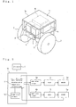
- the traveling dolly according to the present invention has left and right wheels 2 and 3 disposed in a lower portion of a main body of the dolly (hereinafter, referred to as "body") 1 formed by framing to substantial rectangular hexahedral shape.
- the wheels 2 and 3 are arranged on the same rotation axis bilaterally symmetrically, and the body 1 can be tilted to the direction rectangular to the rotation axis.
- a motor 4 as a driving means is connected to the right wheel 2, and a motor 5 as a driving means is connected to the left wheel 3.
- Encoders 4a and 5a are attached to the motors 4 and 5 respectively so as to detect rotation speed thereof.
- a motor driver 6 driving the motors 4 and 5, a battery 8 and a control computer 10 as a control means are mounted to the inside (storage part) of the body 1.
- the control computer 10 calculates torque command value, which is control command value, based on the output of the gyro sensor 7 and the encoder output of the motors 4 and 5.
- the torque command value calculated by the control computer 10 is outputted to the motor driver 6, and the motor driver 6 controls the motors 4 and 5 based on this torque command value.
- a body of a robot (not shown) or the like is disposed on an upper portion 1a of the body 1.
- a traveling dolly according to the present invention is not limited thereto, and what is necessary is just that the dolly comprises one wheel or two or more wheels arranged on the same rotation axis. Namely, with regard to a traveling dolly according to the present invention, what is necessary is just that the control about the dolly translation direction is performed.
- the gyro sensor 7 is connected to the control computer 10, and the output of the gyro sensor 7 (body tilt angular velocity) is inputted into the control computer 10.
- the gyro sensor 7 is an example of a first detection means.
- the control command value calculation means 11 calculates a torque command value for the motors 4 and 5 so as to control the dolly translation direction.
- the traveling dolly is modeled as a single-wheel inverted pendulum in side view.
- a lettering 1C designates the centroid of the body 1 (hereinafter, referred to as "body centroid")
- a lettering S designates the rotation axis of the wheel.
- Fig. 3(b) shows the connection between the motor 4 (or 5) and the wheel 2 (or 3).
- a lettering m 1 designates the mass of the body 1
- a lettering J 1 designates the moment of inertia around the centroid of the body 1
- a lettering m w designates the mass of the wheel
- a lettering J w designates the moment of inertia around the axis of the wheel
- a lettering J m designates the moment of inertia of the motor rotor
- a lettering n designates the gear ratio
- a lettering 1 designates the distance between the rotation axis (axle) S and the body centroid C1
- a lettering r designates the radius of the wheel.
- a letter ⁇ designates the tilt of the body 1 from the vertical direction (a vertical line x passing through the rotation axis S) (hereinafter, referred to as "body tilt angle")
- a letter ⁇ designates the rotation angle of the wheel from the vertical direction (hereinafter, referred to as "wheel angle")
- a letter g designates the gravitational acceleration.
- a lettering l f designates the distance between the rotation axis S and the material point P
- a lettering ⁇ f designates the angle of the material point P from the vertical line x centering on the rotation axis S (hereinafter, referred to as "material point tilt angle").
- the external force moment f is estimated, and the body tilt angle ⁇ at which the gravity moment around the rotation axis S of the body centroid 1C is equal to the external force moment f is set as target body tilt angle ⁇ c .
- the torque command value u which is the control command value is calculated.
- the gravity moment around the rotation axis S of the body centroid 1C is expressed as m 1 gl 1 sin( ⁇ c ).
- the target body tilt angle ⁇ c is set according to the formula (3) so as to satisfy below formula.
- the dummy body tilt angle ⁇ becomes zero (the body centroid 1C is on the x axis) so that the dolly can stops at the initial position even if the external force is applied. Namely, even if large external force is applied on the body 1, the dolly (the position of the wheel) is not moved and the position can be controlled stably at the place, whereby an operator can get on and off easily and goods can be taken on and off easily.
- the external force moment f can be found with the existing gyro sensor 7 and the existing encoders 4a and 5a without providing a sensor or the like newly so as to detect the state quantity.
- the control computer 10 firstly loads the body tilt angular velocity d ⁇ /dt detected by the gyro sensor 7 and the values from the encoders 4a and 5a of the motors 4 and 5 (the wheel rotation angle ⁇ of the wheels 2 and 3) as the state quantity X, and then estimates the external force moment f from these values and differentials and integrals thereof with the formula (13) (step S10).
- step S20 the body tilt angle ⁇ at which the gravity moment of the body centroid 1C balances with the external force moment f estimated in the step S10 is calculated by the formula (15) (step S20).
- the control computer 10 does not transmit the torque command value for moving the body 1 (the torque command value concerning the dolly translation direction and the dolly rotation direction) to the motor driver 6 (the state that the body 1 is at a standstill)
- the body tilt angle ⁇ calculated from the detection value of the gyro sensor 7 becomes a value other than zero
- the target body tilt angle of the body 1 (the target body tilt angle ⁇ c ) is increased and decreased so as to make the body tilt angle ⁇ zero
- the torque command value u is calculated based on this target body tilt angle ⁇ c .
- ⁇ is integrated to the target body tilt angle ⁇ c until the body tilt angle ⁇ becomes zero.
- the direction of a component F of the disturbance applied on the body 1 along the dolly translation direction is considered to be positive.
- the position of the body centroid 1C is moved forward by the disturbance, whereby the body tilt angle ⁇ is increased positively.
- ⁇ is integrated to the target body tilt angle ⁇ c so as to offset the influence of the disturbance. Namely, when the body tilt angle ⁇ generated by the disturbance is the material point tilt angle ⁇ f , ⁇ integrated to the target body tilt angle ⁇ c is negative.
- the formula (4) is materialized when the body tilt angular velocity d ⁇ /dt becomes zero. Namely, the external force moment f generated by the disturbance applied on the body 1 balances with the gravity moment around the rotation axis S of the body centroid 1C. At this time, the integration of ⁇ is stopped.
- the moving distance from the time that the external force applied on the body 1 by the disturbance to the time that the traveling dolly is stopped stably is shorten. Accordingly, for example in the two-wheel state of the traveling dolly (the state that the body 1 is supported only by the wheels 2 and 3), goods can be taken on and off easily and an operator can get on and off easily.
- the body tilt angular velocity d ⁇ /dt may be used so as to estimate the external force applied on the body 1 indirectly.
- the control computer 10 does not transmit the torque command value for moving the body 1 to the motor driver 6.
- the target body tilt angle ⁇ c is increased and decreased until the body tilt angular velocity d ⁇ /dt becomes zero, and the torque command value u is calculated based on this target body tilt angle ⁇ c .
- the slight vibration can be prevented in the region that the absolute value of the body tilt angle ⁇ or the body tilt angular velocity d ⁇ /dt is small, that is, in the vicinity of the balanced position of the body 1.
- the wheel angular velocity d ⁇ /dt is adjusted so as to offset the wheel angular velocity d ⁇ /dt (to make the wheel angular velocity d ⁇ /dt zero).
- ⁇ which is the increase and decrease value of the target body tilt angle ⁇ c , based on the absolute value of the wheel angular velocity d ⁇ /dt.
- the slight vibration can be prevented in the region that the absolute value of the wheel angular velocity d ⁇ /dt is small, that is, in the vicinity of the balanced position of the body 1.
- the body 1 can be stopped immediately. Furthermore, the vibration of the body 1 caused by the sequential fluctuation of the target body tilt angle ⁇ c can be reduced or prevented.
- ⁇ integrated to the target body tilt angle ⁇ c can also be learned sequentially. Namely, for example, the magnitude of the wheel rotation angle ⁇ (the moving direction of the wheel) and the fluctuation of the wheel angular velocity d ⁇ /dt in the case that the external force is applied on the body 1 are regarded as the performance indexes, and ⁇ is learned so as to decrease the magnitude of the wheel rotation angle ⁇ and the fluctuation of the wheel angular velocity d ⁇ /dt.
- the present invention provides control method of a traveling dolly and the traveling dolly which makes the movement of the dolly (a position of a wheel) minimum and enables stable position control in the case that large external force is applied on the dolly so that goods can be taken on and off easily and an operator can get on and off easily. accordingly, the present invention is useful industrially.
Landscapes
- Engineering & Computer Science (AREA)
- Mechanical Engineering (AREA)
- Physics & Mathematics (AREA)
- Automation & Control Theory (AREA)
- General Physics & Mathematics (AREA)
- Transportation (AREA)
- Aviation & Aerospace Engineering (AREA)
- Power Engineering (AREA)
- Remote Sensing (AREA)
- Radar, Positioning & Navigation (AREA)
- Computer Vision & Pattern Recognition (AREA)
- Software Systems (AREA)
- Evolutionary Computation (AREA)
- Artificial Intelligence (AREA)
- Medical Informatics (AREA)
- Health & Medical Sciences (AREA)
- Motorcycle And Bicycle Frame (AREA)
- Feedback Control In General (AREA)
- Electric Propulsion And Braking For Vehicles (AREA)
- Control Of Position, Course, Altitude, Or Attitude Of Moving Bodies (AREA)
Abstract
the control computer 10 estimates external force moment, which is moment of inertia around the rotation axis of the wheels 2 and 3 generated by external force applied on the body 1;
tilt angle of the body 1, which makes gravity moment around the rotation axis of the centroid of the body 1 balances with the external force moment, is set as target body tilt angle; and
based on the target body tilt angle, torque command value for the motors 4 and 5 is calculated.
Description
- The present invention relates to control method of an inverted pendulum-type traveling dolly that a centroid of the body positions above a rotation axis of a wheel. The present invention also relates to the traveling dolly.
- With regard to an inverted pendulum-type traveling dolly and control method thereof, for example, there is known an art described in the
Japanese Patent Laid Open Gazette 2004-295430 - In the
Japanese Patent Laid Open Gazette 2004-295430 - The traveling dolly has a control means calculating control command value to a drive means for the wheel (torque command value to a motor). The control means is so robust as to make the body stand invertedly stably against disturbance. Accordingly, even if the dolly located surface slopes or load is changed, the body can keep on standing stably.
- With regard to the control at the dolly translation direction, wheel angle (rotation angle of the wheel relative to the body); wheel angular velocity which is single integral of the wheel angle, body tilt angle (tilt from the vertical direction) and body tilt angular velocity which is single integral of the body tilt angle are used as state quantities (observed quantities). Hereupon, the body tilt angle is instable so that the dolly cannot stand invertedly stably without feedback control. Accordingly, with regard to the control at the dolly translation direction, the control input is determined so as to make all the state quantities zero.
- However, the control at the dolly translation direction disclosed in the
Japanese Patent Laid Open Gazette 2004-295430 - Namely, since the control at the dolly translation direction has one input and two outputs as mentioned above, when the external force is applied on the body by the movement of the centroid caused by the change of position of an operator on the body, the fluctuation of centroid position caused by mounting a burden on the body, the operator riding on and off or the like, firstly, the axle torque is applied so as to make the body tilt angle fluctuated by the external force return to zero. The body tilt angle is stabilized accordingly and then the axle torque is applied so as to make the wheel angle zero, thereby returning the moved dolly to the initial position.
- When the disturbance is small, the dolly slightly moves and stops at the initial position by the above-mentioned control. However, for example when the external force caused by the large disturbance which is stationary or changes transiently widely is applied on the body, the body tilt angle and the wheel angle cannot be made zero simultaneously, whereby the oscillation centering on the initial position (the position of the dolly before applying the disturbance thereon) is difficult to be converged. Accordingly, the position of the wheel is moved widely (the wheel angle is changed widely). Furthermore, according to the same reason, if an operator jumps on the traveling dolly or similar operation is performed on the dolly, the position of the wheel must be moved widely and an operator cannot get on and off easily.
- Namely, in the dolly translation direction, if a heavy thing is mounted on a position difference from the centroid position of the body or an operator rides on the body and lifts a heavy thing by a suspension mechanism such as an arm provided on the upper portion of the dolly, the centroid position of the body is changed, whereby the dolly cannot stop at the initial position.
- Considering such a traveling dolly as a mobile body on which an operator rides or which carries goods, the occurrence of large movement of the wheel position by the disturbance makes an operator difficult to get on and off and makes goods difficult to be taken on and off.
- Accordingly, the purpose of the present invention is to provide control method of a traveling dolly and the traveling dolly which makes the movement of the dolly (a position of a wheel) minimum and enables stable position control in the case that large external force is applied on the dolly so that goods can be taken on and off easily and an operator can get on and off easily.
- According to the present invention, control method of a traveling dolly having a wheel driven by a drive means, a body supported by the wheel, and a control means commanding control command value to the drive means, a centroid of the body positioning above a rotation axis of the wheel, is characterized in that:
- the control means estimates external force moment, which is moment of inertia around the rotation axis generated by external force applied on the body;
- based on the estimated external force moment, tilt angle of the body, which makes gravity moment around the rotation axis of the body centroid balances with the external force moment, is set as target body tilt angle; and
- based on the target body tilt angle, the control command value is calculated.
- Accordingly, by calculating the control command value based on the target body tilt angle, dummy body tilt angle becomes zero so that the dolly can stops at the initial position even if the external force is applied. Namely, even if large external force is applied on the body, the dolly (the position of the wheel) is not moved and the position can be controlled stably at the place, whereby an operator can get on and off easily and goods can be taken on and off easily.
- With regard to the control method of the traveling dolly according to the present invention, the external force moment is found from disturbance observer. Namely, by using the disturbance observer estimated from the disturbance as state quantity, the external force moment generated by the external force applied on the body by the disturbance is estimated as state quantity so as to offset the estimated disturbance included in the parameter fluctuation controllingly.
- Accordingly, the external force moment can be found with an existing sensor or the like without providing a sensor newly so as to detect the state quantity.
- According to the present invention, control method of a traveling dolly having a wheel driven by a drive means, a body supported by the wheel, and a control means commanding control command value to the drive means, a centroid of the body positioning above a rotation axis of the wheel, is characterized in that:
- the traveling dolly comprises a first detection means detecting at least one of tilt angle and tilt angular velocity of the body and a second detection means detecting at least one of rotation angle and angular velocity of the wheel; and
- in the case that the control means does not transmit control command value for moving the body and the tilt angle or the tilt angular velocity of the body detected by the first detection means becomes a value other than zero, target tilt angle of the body is increased or decreased until the tilt angle or the tilt angular velocity becomes zero, and the control command value is calculated based on the target tilt angle.
- Accordingly, the moving distance from the time that the external force applied on the body by the disturbance to the time that the traveling dolly is stopped stably is shorten. Accordingly, for example in the two-wheel state of the traveling, goods can be taken on and off easily and an operator can get on and off easily.
- With regard to the control method of the traveling dolly according to the present invention, the target tilt angle is increased or decreased corresponding to the absolute value of the tilt angle or the tilt angular velocity of the body detected by the first detection means.
- Accordingly, the slight vibration can be prevented in the region that the absolute value of the body tilt angle or the body tilt angular velocity is small, that is, in the vicinity of the balanced position of the body.
- Furthermore, with regard to the control method of the traveling dolly according to the present invention, the increase and decrease value of the target tilt angle is learned so as to decrease the fluctuation of the tilt angle and the tilt angular velocity based on at least one of the tilt angle and the tilt angular velocity as the performance indexes.
- Accordingly, the slight vibration in the vicinity of the balanced position of the body is prevented efficiently.
- According to the present invention, control method of a traveling dolly having a wheel driven by a drive means, a body supported by the wheel, and a control means commanding control command value to the drive means, a centroid of the body positioning above a rotation axis of the wheel, is characterized in that:
- the traveling dolly comprises a first detection means detecting at least one of tilt angle and tilt angular velocity of the body and a second detection means detecting at least one of rotation angle and angular velocity of the wheel; and
- in the case that the control means does not transmit control command value for moving the body and the angular velocity of the wheel detected by the second detection means becomes a value other than zero, target tilt angle of the body is increased or decreased until the angular velocity becomes zero, and the control command value is calculated based on the target tilt angle.
- Accordingly, the moving distance from the time that the external force applied on the body by the disturbance to the time that the traveling dolly is stopped stably is shorten. Accordingly, for example in the two-wheel state of the traveling, goods can be taken on and off easily and an operator can get on and off easily.
- With regard to the control method of the traveling dolly according to the present invention, the target tilt angle is increased or decreased corresponding to the absolute value of the angular velocity of the wheel detected by the second detection means.
- Accordingly, the slight vibration can be prevented in the region that the absolute value of the angular velocity of the wheel is small, that is, in the vicinity of the balanced position of the body.
- Furthermore, with regard to the control method of the traveling dolly according to the present invention, the increase and decrease value of the target tilt angle is learned so as to decrease the fluctuation of the rotation angle and the angular velocity of the wheel based on at least one of the rotation angle and the angular velocity of the wheel as the performance indexes.
- Accordingly, the slight vibration in the vicinity of the balanced position of the body is prevented efficiently.
- According to the present invention, a traveling dolly having a wheel driven by a drive means, a body supported by the wheel, and a control means commanding control command value to the drive means, a centroid of the body positioning above a rotation axis of the wheel, is characterized in that:
- the control means estimates external force moment, which is moment of inertia around the rotation axis generated by external force applied on the body;
- based on the estimated external force moment, tilt angle of the body, which makes gravity moment around the rotation axis of the body centroid balances with the external force moment, is set as target body tilt angle; and
- based on the target body tilt angle, the control command value is calculated.
- Accordingly, by calculating the control command value based on the target body tilt angle, dummy body tilt angle becomes zero so that the dolly can stops at the initial position even if the external force is applied. Namely, even if large external force is applied on the body, the dolly (the position of the wheel) is not moved and the position can be controlled stably at the place, whereby an operator can get on and off easily and goods can be taken on and off easily.
- According to the present invention, a traveling dolly having a wheel driven by a drive means, a body supported by the wheel, and a control means commanding control command value to the drive means, a centroid of the body positioning above a rotation axis of the wheel, is characterized in that:
- the traveling dolly comprises a first detection means detecting at least one of tilt angle and tilt angular velocity of the body and a second detection means detecting at least one of rotation angle and angular velocity of the wheel; and
- in the case that the control means does not transmit control command value for moving the body and the tilt angle or the tilt angular velocity of the body detected by the first detection means becomes a value other than zero, target tilt angle of the body is increased or decreased until the tilt angle or the tilt angular velocity becomes zero, and the control command value is calculated based on the target tilt angle.
- Accordingly, the moving distance from the time that the external force applied on the body by the disturbance to the time that the traveling dolly is stopped stably is shorten. Accordingly, for example in the two-wheel state of the traveling, goods can be taken on and off easily and an operator can get on and off easily.
- According to the present invention, a traveling dolly having a wheel driven by a drive means, a body supported by the wheel, and a control means commanding control command value to the drive means, a centroid of the body positioning above a rotation axis of the wheel, is characterized in that:
- the traveling dolly comprises a first detection means detecting at least one of tilt angle and tilt angular velocity of the body and a second detection means detecting at least one of rotation angle and angular velocity of the wheel; and
- in the case that the control means does not transmit control command value for moving the body, the angular velocity of the wheel detected by the second detection means becomes a value other than zero, target tilt angle of the body is increased or decreased until the angular velocity becomes zero, and the control command value is calculated based on the target tilt angle.
- Accordingly, the moving distance from the time that the external force applied on the body by the disturbance to the time that the traveling dolly is stopped stably is shorten. Accordingly, for example in the two-wheel state of the traveling, goods can be taken on and off easily and an operator can get on and off easily.
-
- Fig. 1 is a perspective view of schematic construction of a traveling dolly according to the present invention.
- Fig. 2 is a control block diagram of a control system of the traveling dolly.
- Fig. 3 is a drawing of the traveling dolly modeled according to the translation direction.
- Fig. 4 is a flow chart of process steps performed by a control computer.
- Firstly, explanation will be given on schematic construction of an example of a traveling dolly according to the present invention by reference to Fig. 1.
- The traveling dolly according to the present invention has left and
right wheels wheels body 1 can be tilted to the direction rectangular to the rotation axis. - A
motor 4 as a driving means is connected to theright wheel 2, and amotor 5 as a driving means is connected to theleft wheel 3.Encoders 4a and 5a (see Fig. 2) are attached to themotors - A single-
shaft gyro sensor 7 is arranged along the direction rectangular to the rotation axis of thewheels 2 and 3 (the tilt direction of the body 1). Then, thegyro sensor 7 detects tilt angular velocity of the body 1 (hereinafter, referred to as "body tilt angular velocity"). In addition, the sensor measuring the body tilt angular velocity is not limited to the gyro sensor. Various measuring instruments measuring tilt angle or tilt angular velocity, such as a gravitational acceleration sensor and strapped-down, may be used. - A
motor driver 6 driving themotors battery 8 and acontrol computer 10 as a control means are mounted to the inside (storage part) of thebody 1. - The
control computer 10 calculates torque command value, which is control command value, based on the output of thegyro sensor 7 and the encoder output of themotors control computer 10 is outputted to themotor driver 6, and themotor driver 6 controls themotors - A body of a robot (not shown) or the like is disposed on an
upper portion 1a of thebody 1. - Next, explanation will be given on control system of the traveling dolly, constructed as mentioned above, according to fig. 2.
- As shown in Fig. 2, the
control computer 10 as the control means controls the traveling dolly. Thecontrol computer 10 comprises a CPU, a ROM, a RAM and the like and functions as a dolly translation direction control command value calculation means 11 (hereinafter, simply referred to as "control command value calculation means") calculating a control command value concerning the dolly translation direction (the direction rectangular to the rotation axis of thewheels 2 and 3) and as a target value set means 12 setting a target body tilt angle discussed later by executing a control program stored in the ROM. In addition, by executing the control program, thecontrol computer 10 also functions as a dolly rotation direction control command value calculation means calculating a control command value concerning the dolly rotation direction (the turning direction of the rotation axis of thewheels 2 and 3). - Namely, as shown in Fig. 1, with regard to the traveling dolly comprising the two
wheels wheels - The
gyro sensor 7 is connected to thecontrol computer 10, and the output of the gyro sensor 7 (body tilt angular velocity) is inputted into thecontrol computer 10. Namely, thegyro sensor 7 is an example of a first detection means. -
Motor drive circuits motor driver 6 are connected to thecontrol computer 10. Themotor drive circuit 6a is connected to themotor 4 and drives themotor 4 according to a torque command value from thecontrol computer 10. Similarly, themotor drive circuit 6b is connected to themotor 5 and drives themotor 5 according to a torque command value from thecontrol computer 10. Theencoders 4a and 5a of themotors control computer 10 so that the output of each of theencoders 4a and 5a (the rotation angle of each of themotors 4 and 5) is inputted into thecontrol computer 10. Namely, theencoders 4a and 5a are an example of a second detection means. - Net, explanation will be given on the control command value calculation means 11. The control command value calculation means 11 calculates a torque command value for the
motors - Explanation will be given on an example of the design process of the control command value calculation means 11.
- Firstly, as shown in Fig. 3(a), the traveling dolly is modeled as a single-wheel inverted pendulum in side view. A
lettering 1C designates the centroid of the body 1 (hereinafter, referred to as "body centroid"), and a lettering S designates the rotation axis of the wheel. Fig. 3(b) shows the connection between the motor 4 (or 5) and the wheel 2 (or 3). - In Fig. 3, a lettering m1 designates the mass of the
body 1, a lettering J1 designates the moment of inertia around the centroid of thebody 1, a lettering mw designates the mass of the wheel, a lettering Jw designates the moment of inertia around the axis of the wheel, a lettering Jm designates the moment of inertia of the motor rotor, a lettering n designates the gear ratio, alettering 1 designates the distance between the rotation axis (axle) S and the body centroid C1, and a lettering r designates the radius of the wheel. - Each of the parameters m1, J1, mw, Jw, Jm, n, l and r can be found by calculation or observation. A letter η designates the tilt of the
body 1 from the vertical direction (a vertical line x passing through the rotation axis S) (hereinafter, referred to as "body tilt angle"), a letter θ designates the rotation angle of the wheel from the vertical direction (hereinafter, referred to as "wheel angle"), and a letter g designates the gravitational acceleration. - Then, an equation of motion is made concerning the single-wheel inverted pendulum shown in Fig. 3(a). Namely, the equation of motion made supposing that a torque command value u is inputted into the control model is below.


- When external force is applied on the
body 1 by disturbance such as movement of an operator or loading of a burden, the moment of inertia around the rotation axis S of the wheel is generated by a component F of the external force along the dolly translation direction. When the moment of inertia around the rotation axis S of thebody 1 caused by the external force (hereinafter, referred to as "external force moment f") is exchanged for gravity moment of a material point P having mass mf around the rotation axis S, the external force moment f is formulated by below formula.
- Herein, a lettering lf designates the distance between the rotation axis S and the material point P, and a lettering ηf designates the angle of the material point P from the vertical line x centering on the rotation axis S (hereinafter, referred to as "material point tilt angle").
- In this control, the external force moment f is estimated, and the body tilt angle η at which the gravity moment around the rotation axis S of the
body centroid 1C is equal to the external force moment f is set as target body tilt angle ηc. Based on the target body tilt angle ηc, the torque command value u which is the control command value is calculated. - Namely, the gravity moment around the rotation axis S of the
body centroid 1C is expressed as m1gl1sin(ηc). Accordingly, the target body tilt angle ηc is set according to the formula (3) so as to satisfy below formula.
- By calculating the torque command value u based on the target body tilt angle ηc found from the estimated external force moment f by the formula (4), the dummy body tilt angle η becomes zero (the
body centroid 1C is on the x axis) so that the dolly can stops at the initial position even if the external force is applied. Namely, even if large external force is applied on thebody 1, the dolly (the position of the wheel) is not moved and the position can be controlled stably at the place, whereby an operator can get on and off easily and goods can be taken on and off easily. - Explanation will be given below on the estimation method of the external force moment f.
- Supposing that η in the equation of motion shown in formulas (1) and (2) is small, the linearization is performed and the matrix display is performed so as to lead below formula.

- Herein, M in the formula (5) is shown below.

- A0 in the formula (5) is shown below.

- B0 in the formula (5) is shown below.

- Accordingly, below state equation is led from the formulas (5) to (8).

- Herein, the state quantity X is shown below.
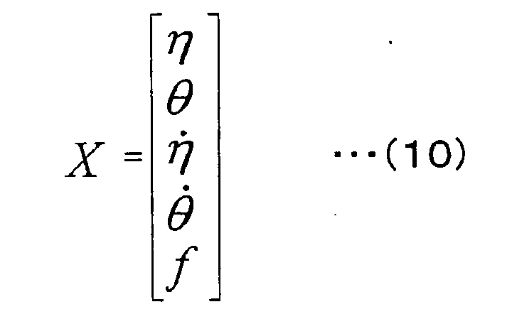
- By multiplying both sides of the formula (9) by M-1 from the left, below formula is led.

- Herein, M-1M = 1. Supposing that M-1A0 = A and M-1B0 = B, below formula is led.

- Herein, with regard to the state quantity (observed quantity) X observed in the above-mentioned control system, the body tilt angular velocity dη/dt can be measured by the
gyro sensor 7, and the wheel rotation angle θ can be measured by theencoders 4a and 5a. Accordingly, by differentiation and integration, the body tilt angle η which is single integral of the body tilt angular velocity dη /dt and the wheel angular velocity dθ/dt which is single differential of the wheel rotation angle θ are calculated. - As the state quantity X, the combination such as the body tilt angle η and the wheel rotation angle θ or the body tilt angle η and the wheel angular velocity dθ/dt can be adopted.
- Accordingly, a disturbance observer estimating the external force moment f which is unknown state quantity in the formula (12) is constructed based on below formula.

- Herein, a lettering X designates the state quantity (displacement and speed), a lettering C designates the damper term, and a lettering L designates the observer gain. A lettering y designates the observed quantity and shows the body tilt angle η, the body tilt angular velocity dη/dt, the wheel rotation angle θ and the wheel angular velocity dθ/dt in this case. When a part of the state quantities is unknown, the quantity is calculated by approximate differentiation or integration.
- For example, when four state quantities is known which is the body tilt angular velocity dη/dt detected by the
gyro sensor 7, the wheel rotation angle θ measured by theencoders 4a and 5a, the body tilt angle η being single integral of the body tilt angular velocity dη/dt, and the wheel angular velocity dθ/dt being single differential of the wheel rotation angle θ, C in the formula (13) is below matrix.
- Then, the external force moment f is estimated by the formula (13), and the relation of the formula (4) is materialized.
- Accordingly, it is necessary to set the target body tilt angle ηc in the formula (4) so as to balance with the external force moment f estimated by the disturbance observer estimating unknown state quantity. Essentially, the target body tilt angle is set to 0 so as to stabilize the inverted pendulum shown in fig. 3(a). However, in this control, the target body tilt angle ηc led by the formula (4) is given by below formula so as to offset the external force moment f which is the influence of the external force.

- By the disturbance observer estimating unknown state quantity as mentioned above, the external force moment f can be found with the existing
gyro sensor 7 and the existingencoders 4a and 5a without providing a sensor or the like newly so as to detect the state quantity. - Next, explanation will be given on the process performed by the
control computer 10 constructed as mentioned above according to a flow chart shown in Fig. 4. - As shown in Fig. 4, the
control computer 10 firstly loads the body tilt angular velocity dη/dt detected by thegyro sensor 7 and the values from theencoders 4a and 5a of themotors 4 and 5 (the wheel rotation angle θ of thewheels 2 and 3) as the state quantity X, and then estimates the external force moment f from these values and differentials and integrals thereof with the formula (13) (step S10). - Next, the body tilt angle η at which the gravity moment of the
body centroid 1C balances with the external force moment f estimated in the step S10 is calculated by the formula (15) (step S20). - The body tilt angle η calculated in the step S20 is set into the target value set means 12 as the target body tilt angle ηc (step S30).
- Then, based on the target body tilt angle ηc set at the step S30, the control command value calculation means 11 calculates the torque command value u for the
motor drive circuits motors 4 and 5 (step S40). The calculated torque command value u is inputted into themotor drive circuits motors body 1. - In addition, the above-mentioned process of the steps S10 to S40 is performed at fixed intervals (for example, 10ms).
- Upon this, the external force applied on the
body 1 may be estimated indirectly from the body tilt angle η instead of finding the external force moment f directly as mentioned above. - When the disturbance is applied on the
body 1, thebody 1 is tilted and the body tilt angle η becomes a value other than zero. Namely, in the case that thebody 1 is at a standstill stably (the body tilt angle η is zero) and thecontrol computer 10 does not transmit the torque command value concerning the dolly translation direction and the dolly rotation direction, that is, the case that thebody 1 does not move along longitudinal or turning direction and is at a standstill, for example the case that any operator does not ride on thebody 1, the body tilt angle η being a value other than zero means that the external force is applied on thebody 1. Then, when the body tilt angle η becomes a value other than zero by the external force applied on thebody 1, the body tilt angle η is adjusted so as to offset the body tilt angle η (to make the body tilt angle η zero). - Namely, in the state that the
control computer 10 does not transmit the torque command value for moving the body 1 (the torque command value concerning the dolly translation direction and the dolly rotation direction) to the motor driver 6 (the state that thebody 1 is at a standstill), when the body tilt angle η calculated from the detection value of thegyro sensor 7 becomes a value other than zero, the target body tilt angle of the body 1 (the target body tilt angle ηc) is increased and decreased so as to make the body tilt angle η zero, and the torque command value u is calculated based on this target body tilt angle ηc. - Concretely, when the disturbance is applied on the
body 1 and the body tilt angle η becomes a value other than zero, Δη is integrated to the target body tilt angle ηc until the body tilt angle η becomes zero. Herein, as shown in Fig. 3 (a), the direction of a component F of the disturbance applied on thebody 1 along the dolly translation direction is considered to be positive. In this case, the position of thebody centroid 1C is moved forward by the disturbance, whereby the body tilt angle η is increased positively. Supposing that the generated body tilt angle η is the material point tilt angle ηf similarly to the above, Δη is integrated to the target body tilt angle ηc so as to offset the influence of the disturbance. Namely, when the body tilt angle η generated by the disturbance is the material point tilt angle ηf, Δη integrated to the target body tilt angle ηc is negative. - By integrating Δη to the target body tilt angle ηc until the body tilt angle η becomes zero, the formula (4) is materialized when the body tilt angular velocity dη/dt becomes zero. Namely, the external force moment f generated by the disturbance applied on the
body 1 balances with the gravity moment around the rotation axis S of thebody centroid 1C. At this time, the integration of Δη is stopped. - Accordingly, by estimating the external force applied on the
body 1 indirectly from the body tilt angle η and increasing and decreasing the target body tilt angle ηc so as to offset the external force, the moving distance from the time that the external force applied on thebody 1 by the disturbance to the time that the traveling dolly is stopped stably is shorten. Accordingly, for example in the two-wheel state of the traveling dolly (the state that thebody 1 is supported only by thewheels 2 and 3), goods can be taken on and off easily and an operator can get on and off easily. - In addition, instead of the body tilt angle η, the body tilt angular velocity d η/dt may be used so as to estimate the external force applied on the
body 1 indirectly. In this case, thecontrol computer 10 does not transmit the torque command value for moving thebody 1 to themotor driver 6. When the body tilt angular velocity dη/dt detected by thegyro sensor 7 is not zero, the target body tilt angle ηc is increased and decreased until the body tilt angular velocity d η /dt becomes zero, and the torque command value u is calculated based on this target body tilt angle ηc. - When the external force applied on the
body 1 is estimated indirectly from the body tilt angle η or the body tilt angular velocity dη/dt so as to increase and decrease the target body tilt angle ηc, it is preferable to increase and decrease Δη, which is the increase and decrease value of the target body tilt angle ηc, based on the absolute value of the body tilt angle η or the body tilt angular velocity dη/dt. - Namely, when the external force applied on the
body 1 is large and the absolute value of the body tilt angle η or the body tilt angular velocity dη/dt generated by the external force is large, the absolute value of Δη is increased. Then, following the decrease of the absolute value of the body tilt angle η by the target body tilt angle ηc offsetting the influence of the disturbance, the absolute value of Δη is decreased. - Accordingly, by increasing and decreasing Δη integrated to the target body tilt angle ηc according to the absolute value of the body tilt angle η or the body tilt angular velocity dη/dt, the slight vibration can be prevented in the region that the absolute value of the body tilt angle η or the body tilt angular velocity dη/dt is small, that is, in the vicinity of the balanced position of the
body 1. - Therefore, even if the external force applied on the
body 1 is large, thebody 1 can be stopped immediately. Furthermore, the vibration of thebody 1 caused by the sequential fluctuation of the target body tilt angle ηc can be reduced or prevented. Δη integrated to the target body tilt angle ηc can be learned sequentially. Namely, for example, the magnitude of the body tilt angle η and the fluctuation of the body tilt angular velocity dη/dt in the case that the external force is applied on thebody 1 are regarded as the performance indexes, and Δη is learned so as to decrease the magnitude of the body tilt angle η and the fluctuation of the body tilt angular velocity dη/dt. - For example, for decreasing the magnitude of the body tilt angle η in the case that the external force is applied on the
body 1, what is necessary is just to increase Δη integrated to the target body tilt angle ηc. As large as Δη becomes, as soon as the target body tilt angle ηc reaches the state balancing with the external force (the state that the formula (4) is materialized) so that the gravity moment of thebody centroid 1C balances with the external force moment f. However, if Δη is increased, the slight vibration in the vicinity of the balanced position of thebody 1 becomes large in the balancing process. - The body tilt angular velocity dη/dt is decreased following the integration of Δη to the target body tilt angle ηc from the time that the external force is applied on the
body 1. Accordingly, by decreasing Δη following this decrease of the body tilt angular velocity dη/dt, the fluctuation of the body tilt angular velocity dη/dt becomes small. - Accordingly, the correspondence between Δη integrated to the target body tilt angle ηc and the body tilt angular velocity dη/dt in the case that the external force is applied on the
body 1 is memorized sequentially in the RAM or the like of thecontrol computer 10. Therefore, Δη which makes both the body tilt angle η and the body tilt angular velocity d η/dt small is learned finally so as to prevent the slight vibration in the vicinity of the balanced position of thebody 1 efficiently. - The external force applied on the
body 1 can also be estimated indirectly from the wheel angular velocity dθ/dt. In addition, the explanation overlapping the case estimating the external force applied on thebody 1 from the body tilt angle η will be omitted below. - When the external force is applied on the
body 1, thebody 1 is tilted. Thewheels body 1, whereby the wheel angular velocity dθ/dt becomes a value other than zero. Namely, in the case that thebody 1 stops stably (the wheel angular velocity d θ /dt is zero) and thecontrol computer 10 does not transmit the torque command value concerning the dolly translation direction and the dolly rotation direction, such as the case that the time that an operator does not operates the dolly, the wheel angular velocity dθ/dt being a value other than zero means that the external force is applied on thebody 1. Then, when the wheel angular velocity d θ /dt becomes a value other than zero by the external force applied on thebody 1, the wheel angular velocity dθ/dt is adjusted so as to offset the wheel angular velocity dθ/dt (to make the wheel angular velocity d θ /dt zero). - Namely, in the state that the
control computer 10 does not transmit the torque command value for moving thebody 1 to themotor driver 6, when the wheel angular velocity d θ /dt calculated from the wheel rotation angle θ measured by theencoders 4a and 5a becomes a value other than zero, the body tilt angle ηc is increased and decreased so as to make the wheel angular velocity dθ/dt zero, and the torque command value u is calculated based on this target body tilt angle ηc. - Concretely, when the disturbance is applied on the
body 1 and the wheel angular velocity dθ/dt becomes a value other than zero, Δη is integrated to the target body tilt angle η c until the wheel angular velocity d θ /dt becomes zero. Herein, as shown in Fig. 3 (a), the direction of a component F of the disturbance applied on thebody 1 along the dolly translation direction is considered to be positive. In this case, the position of thebody centroid 1C is moved forward by the disturbance, whereby the body tilt angle η is increased positively. Supposing that the generated body tilt angle η is the material point tilt angle ηf similarly to the above, Δη is integrated to the target body tilt angle ηc so as to offset the influence of the disturbance. Namely, when the body tilt angle η generated by the disturbance is the material point tilt angle ηf, Δη integrated to the target body tilt angle ηc is negative. - By integrating Δη to the target body tilt angle ηc until the body tilt angle η becomes zero, the formula (4) is materialized when the body tilt angular velocity dη/dt becomes zero. Namely, the external force moment f generated by the disturbance applied on the
body 1 balances with the gravity moment around the rotation axis S of thebody centroid 1C. At this time, the integration of Δη is stopped. - Accordingly, by estimating the external force applied on the
body 1 indirectly from the wheel angular velocity dθ/dt and increasing and decreasing the target body tilt angle ηc so as to offset the external force, the same effect as was previously mentioned can be obtained. - When the external force applied on the
body 1 is estimated indirectly from the wheel angular velocity d θ /dt so as to increase and decrease the target body tilt angle ηc, it is also preferable to increase and decrease Δη, which is the increase and decrease value of the target body tilt angle ηc, based on the absolute value of the wheel angular velocity dθ/dt. - Namely, when the external force applied on the
body 1 is large and the absolute value of the wheel angular velocity dθ/dt generated by the external force is large, the absolute value of Δη is increased. Then, following the decrease of the absolute value of the body tilt angle η by the target body tilt angle ηc offsetting the influence of the disturbance, the absolute value of Δη is decreased. - Accordingly, by increasing and decreasing Δη integrated to the target body tilt angle ηc according to the absolute value of the wheel angular velocity dθ/dt, the slight vibration can be prevented in the region that the absolute value of the wheel angular velocity dθ/dt is small, that is, in the vicinity of the balanced position of the
body 1. - Therefore, even if the external force applied on the
body 1 is large, thebody 1 can be stopped immediately. Furthermore, the vibration of thebody 1 caused by the sequential fluctuation of the target body tilt angle ηc can be reduced or prevented. - In this case, Δη integrated to the target body tilt angle ηc can also be learned sequentially. Namely, for example, the magnitude of the wheel rotation angle θ (the moving direction of the wheel) and the fluctuation of the wheel angular velocity dθ/dt in the case that the external force is applied on the
body 1 are regarded as the performance indexes, and Δη is learned so as to decrease the magnitude of the wheel rotation angle θ and the fluctuation of the wheel angular velocity dθ/dt. - For example, for decreasing the magnitude of the moving direction of the wheel in the case that the external force is applied on the
body 1, what is necessary is just to increase Δη integrated to the target body tilt angle ηc. As large as Δη becomes, as soon as the target body tilt angle ηc reaches the state balancing with the external force (the state that the formula (4) is materialized) so that the gravity moment of thebody centroid 1C balances with the external force moment f. However, if Δη is increased, the slight vibration in the vicinity of the balanced position of thebody 1 becomes large in the balancing process. - The wheel angular velocity dθ/dt is decreased following the integration of Δη to the target body tilt angle ηc from the time that the external force is applied on the
body 1. Accordingly, by decreasing Δη following this decrease of the wheel angular velocity dθ/dt, the fluctuation of the wheel angular velocity dθ/dt becomes small. - Accordingly, the correspondence between Δη integrated to the target body tilt angle ηc and the wheel angular velocity dθ/dt in the case that the external force is applied on the
body 1 is memorized sequentially in the RAM or the like of thecontrol computer 10. Therefore, Δη which makes both the moving direction of the wheel and the wheel angular velocity d θ /dt small finally is learned so as to prevent the slight vibration in the vicinity of the balanced position of thebody 1 efficiently. - The present invention provides control method of a traveling dolly and the traveling dolly which makes the movement of the dolly (a position of a wheel) minimum and enables stable position control in the case that large external force is applied on the dolly so that goods can be taken on and off easily and an operator can get on and off easily. accordingly, the present invention is useful industrially.
Claims (11)
- Control method of a traveling dolly having a wheel driven by a drive means, a body supported by the wheel, and a control means commanding control command value to the drive means, a centroid of the body positioning above a rotation axis of the wheel, characterized in that:the control means estimates external force moment, which is moment of inertia around the rotation axis generated by external force applied on the body;based on the estimated external force moment, tilt angle of the body, which makes gravity moment around the rotation axis of the body centroid balances with the external force moment, is set as target body tilt angle; andbased on the target body tilt angle, the control command value is calculated.
- The control method of the traveling dolly as set forth in claim 1, wherein the external force moment is found from disturbance observer.
- Control method of a traveling dolly having a wheel driven by a drive means, a body supported by the wheel, and a control means commanding control command value to the drive means, a centroid of the body positioning above a rotation axis of the wheel, characterized in that:the traveling dolly comprises a first detection means detecting at least one of tilt angle and tilt angular velocity of the body and a second detection means detecting at least one of rotation angle and angular velocity of the wheel; andin the case that the control means does not transmit control command value for moving the body and the tilt angle or the tilt angular velocity of the body detected by the first detection means becomes a value other than zero, target tilt angle of the body is increased or decreased until the tilt angle or the tilt angular velocity becomes zero, and the control command value is calculated based on the target tilt angle.
- The control method of the traveling dolly as set forth in claim 3, wherein the target tilt angle is increased or decreased corresponding to the absolute value of the tilt angle or the tilt angular velocity of the body detected by the first detection means.
- The control method of the traveling dolly as set forth in claim 4, wherein the increase and decrease value of the target tilt angle is learned so as to decrease the fluctuation of the tilt angle and the tilt angular velocity based on at least one of the tilt angle and the tilt angular velocity as the performance indexes.
- Control method of a traveling dolly having a wheel driven by a drive means, a body supported by the wheel, and a control means commanding control command value to the drive means, a centroid of the body positioning above a rotation axis of the wheel, characterized in that:the traveling dolly comprises a first detection means detecting at least one of tilt angle and tilt angular velocity of the body and a second detection means detecting at least one of rotation angle and angular velocity of the wheel; andin the case that the control means does not transmit control command value for moving the body and the angular velocity of the wheel detected by the second detection means becomes a value other than zero, target tilt angle of the body is increased or decreased until the angular velocity becomes zero, and the control command value is calculated based on the target tilt angle.
- The control method of the traveling dolly as set forth in claim 6, wherein the target tilt angle is increased or decreased corresponding to the absolute value of the angular velocity of the wheel detected by the second detection means.
- The control method of the traveling dolly as set forth in claim 7, wherein the increase and decrease value of the target tilt angle is learned so as to decrease the fluctuation of the rotation angle and the angular velocity of the wheel based on at least one of the rotation angle and the angular velocity of the wheel as the performance indexes.
- A traveling dolly having a wheel driven by a drive means, a body supported by the wheel, and a control means commanding control command value to the drive means, a centroid of the body positioning above a rotation axis of the wheel, characterized in that:the control means estimates external force moment, which is moment of inertia around the rotation axis generated by external force applied on the body;based on the estimated external force moment, tilt angle of the body, which makes gravity moment around the rotation axis of the body centroid balances with the external force moment, is set as target body tilt angle; andbased on the target body tilt angle, the control command value is calculated.
- A traveling dolly having a wheel driven by a drive means, a body supported by the wheel, and a control means commanding control command value to the drive means, a centroid of the body positioning above a rotation axis of the wheel, characterized in that:the traveling dolly comprises a first detection means detecting at least one of tilt angle and tilt angular velocity of the body and a second detection means detecting at least one of rotation angle and angular velocity of the wheel; andin the case that the control means does not transmit control command value for moving the body and the tilt angle or the tilt angular velocity of the body detected by the first detection means becomes a value other than zero, target tilt angle of the body is increased or decreased until the tilt angle or the tilt angular velocity becomes zero, and the control command value is calculated based on the target tilt angle.
- A traveling dolly having a wheel driven by a drive means, a body supported by the wheel, and a control means commanding control command value to the drive means, a centroid of the body positioning above a rotation axis of the wheel, characterized in that:the traveling dolly comprises a first detection means detecting at least one of tilt angle and tilt angular velocity of the body and a second detection means detecting at least one of rotation angle and angular velocity of the wheel; andin the case that the control means does not transmit control command value for moving the body, the angular velocity of the wheel detected by the second detection means becomes a value other than zero, target tilt angle of the body is increased or decreased until the angular velocity becomes zero, and the control command value is calculated based on the target tilt angle.
Applications Claiming Priority (2)
| Application Number | Priority Date | Filing Date | Title |
|---|---|---|---|
| JP2005190781A JP4760162B2 (en) | 2005-06-29 | 2005-06-29 | Control method of mobile cart and mobile cart |
| PCT/JP2006/313201 WO2007001083A1 (en) | 2005-06-29 | 2006-06-27 | Control method for moving carriage |
Publications (3)
| Publication Number | Publication Date |
|---|---|
| EP1788469A1 true EP1788469A1 (en) | 2007-05-23 |
| EP1788469A4 EP1788469A4 (en) | 2011-11-30 |
| EP1788469B1 EP1788469B1 (en) | 2012-10-10 |
Family
ID=37595314
Family Applications (1)
| Application Number | Title | Priority Date | Filing Date |
|---|---|---|---|
| EP06767778A Ceased EP1788469B1 (en) | 2005-06-29 | 2006-06-27 | Control method for moving carriage |
Country Status (6)
| Country | Link |
|---|---|
| US (1) | US8155828B2 (en) |
| EP (1) | EP1788469B1 (en) |
| JP (1) | JP4760162B2 (en) |
| KR (1) | KR100950952B1 (en) |
| CN (1) | CN100530018C (en) |
| WO (1) | WO2007001083A1 (en) |
Cited By (1)
| Publication number | Priority date | Publication date | Assignee | Title |
|---|---|---|---|---|
| WO2009072215A1 (en) | 2007-12-03 | 2009-06-11 | Toyota Jidosha Kabushiki Kaisha | Travel gear and its controlling method |
Families Citing this family (43)
| Publication number | Priority date | Publication date | Assignee | Title |
|---|---|---|---|---|
| CN100557539C (en) * | 2005-07-26 | 2009-11-04 | 松下电器产业株式会社 | Inverted two-wheel walking robot and control method thereof |
| JP2008263676A (en) * | 2007-04-10 | 2008-10-30 | Toyota Central R&D Labs Inc | Self-propelled vehicle and its control device and control method |
| JP4735598B2 (en) * | 2007-04-27 | 2011-07-27 | トヨタ自動車株式会社 | Inverted wheel type moving body and control method thereof |
| JP4867823B2 (en) | 2007-07-09 | 2012-02-01 | トヨタ自動車株式会社 | Inverted wheel type moving body and control method thereof |
| JP5115133B2 (en) * | 2007-10-12 | 2013-01-09 | 株式会社エクォス・リサーチ | vehicle |
| JP4605204B2 (en) | 2007-10-24 | 2011-01-05 | トヨタ自動車株式会社 | Inverted pendulum type moving body and control method thereof |
| JP4992754B2 (en) * | 2008-02-25 | 2012-08-08 | トヨタ自動車株式会社 | Inverted wheeled mobile robot and its control method |
| JP5228560B2 (en) * | 2008-03-25 | 2013-07-03 | トヨタ自動車株式会社 | Inverted traveling robot and control method thereof |
| WO2010032493A1 (en) * | 2008-09-17 | 2010-03-25 | 株式会社村田製作所 | Fall prevention controller and computer program |
| WO2010035324A1 (en) * | 2008-09-25 | 2010-04-01 | トヨタ自動車株式会社 | Self-propelled vehicle, and device and method for controlling same |
| JP2010125969A (en) * | 2008-11-27 | 2010-06-10 | Toyota Motor Corp | Movable body |
| JP5093185B2 (en) * | 2009-04-28 | 2012-12-05 | トヨタ自動車株式会社 | Inverted moving body control device |
| JP4957769B2 (en) | 2009-09-08 | 2012-06-20 | トヨタ自動車株式会社 | Traveling apparatus and control method thereof |
| US8513917B2 (en) * | 2009-09-18 | 2013-08-20 | Honda Motor Co., Ltd. | Recharging system for a rechargeable battery of an inverted pendulum type vehicle |
| US8567537B2 (en) * | 2009-09-18 | 2013-10-29 | Honda Motor Co., Ltd | Inverted pendulum type vehicle |
| DE112009005274B4 (en) | 2009-09-23 | 2015-09-24 | Honda Motor Co., Ltd. | Regulation / control device for inverspendelartiges vehicle |
| JP5560234B2 (en) * | 2011-05-31 | 2014-07-23 | トヨタテクニカルディベロップメント株式会社 | Center of gravity angle estimation method and inverted wheel type traveling body controlled by the method |
| JP5182401B2 (en) * | 2011-08-31 | 2013-04-17 | トヨタ自動車株式会社 | Traveling apparatus and control method thereof |
| JP5786633B2 (en) * | 2011-10-13 | 2015-09-30 | トヨタ自動車株式会社 | MOBILE BODY CONTROL DEVICE, ITS CONTROL METHOD, AND PROGRAM |
| JP5716873B2 (en) * | 2012-09-18 | 2015-05-13 | 株式会社村田製作所 | Moving body |
| TW201446561A (en) * | 2013-06-05 | 2014-12-16 | Cal Comp Electronics & Comm Co | Carrier |
| CN103407530A (en) * | 2013-07-14 | 2013-11-27 | 刘军民 | Independent self-balance device of transverse two-wheeled electric bicycle |
| CN103792946B (en) * | 2014-02-14 | 2016-08-24 | 上海创绘机器人科技有限公司 | The signal processing method of motor type reversible pendulum system control and Intelligent self-balancing car whistle control system |
| CN103941741B (en) * | 2014-04-28 | 2016-06-01 | 北京控制工程研究所 | Based on the control moment gyro frame corners speed control method for determination of amount of zero motion |
| CA3278463A1 (en) | 2016-02-23 | 2025-10-27 | Deka Products Limited Partnership | Mobility device control system |
| US10908045B2 (en) | 2016-02-23 | 2021-02-02 | Deka Products Limited Partnership | Mobility device |
| US11399995B2 (en) | 2016-02-23 | 2022-08-02 | Deka Products Limited Partnership | Mobility device |
| US10926756B2 (en) | 2016-02-23 | 2021-02-23 | Deka Products Limited Partnership | Mobility device |
| EP3443426B1 (en) | 2016-04-14 | 2022-10-26 | DEKA Products Limited Partnership | A transporter and a control method for a transporter |
| CN107472419A (en) * | 2016-06-07 | 2017-12-15 | 韩莹光 | A kind of method for adjusting gravity center of balance car |
| CN107685325B (en) * | 2016-08-10 | 2020-04-03 | 北京小米移动软件有限公司 | Self-balancing robot and its speed control device and speed control method |
| CN106828627A (en) * | 2017-04-06 | 2017-06-13 | 桂林理工大学 | Flying wheel and bicycle machines people |
| USD829612S1 (en) | 2017-05-20 | 2018-10-02 | Deka Products Limited Partnership | Set of toggles |
| USD1047785S1 (en) | 2017-05-20 | 2024-10-22 | Deka Products Limited Partnership | Toggle control device |
| USD846452S1 (en) | 2017-05-20 | 2019-04-23 | Deka Products Limited Partnership | Display housing |
| JP6709292B2 (en) * | 2017-07-27 | 2020-06-10 | 納恩博(北京)科技有限公司Ninebot (Beijing) Tech Co.,Ltd. | Roller skating device and electric balance car |
| JP2021527204A (en) | 2018-06-07 | 2021-10-11 | デカ・プロダクツ・リミテッド・パートナーシップ | Systems and methods for delivery multipurpose service execution |
| KR20210103217A (en) | 2020-02-13 | 2021-08-23 | 조유진 | Electric dolly that can be controlled by the application |
| CN112506049A (en) * | 2020-11-02 | 2021-03-16 | 江阴市智行工控科技有限公司 | Anti-shaking positioning control method based on interference observer and generalized load position tracking |
| KR102909027B1 (en) * | 2021-07-01 | 2026-01-07 | 현대자동차주식회사 | Movable object and method of controlling the same |
| KR20240053217A (en) | 2022-10-17 | 2024-04-24 | 현대자동차주식회사 | Robot and control method for the same |
| JP2024088228A (en) * | 2022-12-20 | 2024-07-02 | 株式会社豊田自動織機 | Loading and unloading vehicles |
| DE102024128292A1 (en) * | 2023-10-24 | 2025-04-24 | Sew-Eurodrive Gmbh & Co Kg | Handset, especially a handset that can be moved on a floor surface |
Family Cites Families (19)
| Publication number | Priority date | Publication date | Assignee | Title |
|---|---|---|---|---|
| JP2530652B2 (en) | 1987-06-05 | 1996-09-04 | シ−ケ−ディ株式会社 | Attitude control method for coaxial two-wheeled vehicles |
| JPH0415713A (en) * | 1990-05-01 | 1992-01-21 | Komatsu Ltd | Posture control method for parallel two-wheeled vehicle |
| JP3070015B2 (en) | 1990-11-30 | 2000-07-24 | 本田技研工業株式会社 | Travel control system for unstable vehicles |
| US7546889B2 (en) * | 1993-02-24 | 2009-06-16 | Deka Products Limited Partnership | Guided control of a transporter |
| US5701965A (en) | 1993-02-24 | 1997-12-30 | Deka Products Limited Partnership | Human transporter |
| US6302230B1 (en) | 1999-06-04 | 2001-10-16 | Deka Products Limited Partnership | Personal mobility vehicles and methods |
| JP4449201B2 (en) * | 2000-10-04 | 2010-04-14 | 株式会社ジェイテクト | Steering torque estimation device, steering torque estimation method, and steering device |
| JP4063560B2 (en) | 2002-03-18 | 2008-03-19 | 株式会社国際電気通信基礎技術研究所 | Communication robot |
| CN100361862C (en) | 2002-11-20 | 2008-01-16 | 中国科学技术大学 | Self-balancing two-wheeled electric vehicle |
| JP2004276727A (en) * | 2003-03-14 | 2004-10-07 | Matsushita Electric Works Ltd | Mobile equipment for person, and its braking method |
| JP4138546B2 (en) * | 2003-03-26 | 2008-08-27 | トヨタ自動車株式会社 | Mobile cart and control method of mobile cart |
| WO2004110854A1 (en) * | 2003-06-12 | 2004-12-23 | Sony Corporation | Coaxial motorcycle |
| JP4296853B2 (en) * | 2003-06-12 | 2009-07-15 | トヨタ自動車株式会社 | Coaxial motorcycle |
| JP4503267B2 (en) * | 2003-11-21 | 2010-07-14 | オリエンタルモーター株式会社 | Method and apparatus for high-speed positioning of electric motor |
| US7424927B2 (en) * | 2004-04-28 | 2008-09-16 | Yamaha Hatsudoki Kabushiki Kaisha | Vehicle, vehicle control device and vehicle control method |
| CN100557539C (en) * | 2005-07-26 | 2009-11-04 | 松下电器产业株式会社 | Inverted two-wheel walking robot and control method thereof |
| JP4872276B2 (en) * | 2005-09-02 | 2012-02-08 | トヨタ自動車株式会社 | Traveling body |
| JP4802622B2 (en) * | 2005-09-06 | 2011-10-26 | トヨタ自動車株式会社 | Running body and method of adjusting running body |
| JP4291822B2 (en) * | 2006-02-03 | 2009-07-08 | トヨタ自動車株式会社 | Inverted wheel type traveling body |
-
2005
- 2005-06-29 JP JP2005190781A patent/JP4760162B2/en not_active Expired - Fee Related
-
2006
- 2006-06-27 CN CNB2006800009936A patent/CN100530018C/en not_active Expired - Fee Related
- 2006-06-27 US US11/994,379 patent/US8155828B2/en not_active Expired - Fee Related
- 2006-06-27 EP EP06767778A patent/EP1788469B1/en not_active Ceased
- 2006-06-27 KR KR1020077029776A patent/KR100950952B1/en not_active Expired - Fee Related
- 2006-06-27 WO PCT/JP2006/313201 patent/WO2007001083A1/en not_active Ceased
Cited By (2)
| Publication number | Priority date | Publication date | Assignee | Title |
|---|---|---|---|---|
| WO2009072215A1 (en) | 2007-12-03 | 2009-06-11 | Toyota Jidosha Kabushiki Kaisha | Travel gear and its controlling method |
| EP2093100A4 (en) * | 2007-12-03 | 2009-12-16 | Toyota Motor Co Ltd | CHASSIS AND CONTROL PROCESS THEREFOR |
Also Published As
| Publication number | Publication date |
|---|---|
| EP1788469A4 (en) | 2011-11-30 |
| JP4760162B2 (en) | 2011-08-31 |
| US20090030597A1 (en) | 2009-01-29 |
| KR100950952B1 (en) | 2010-04-01 |
| US8155828B2 (en) | 2012-04-10 |
| JP2007011634A (en) | 2007-01-18 |
| KR20080011705A (en) | 2008-02-05 |
| CN101040233A (en) | 2007-09-19 |
| CN100530018C (en) | 2009-08-19 |
| WO2007001083A1 (en) | 2007-01-04 |
| EP1788469B1 (en) | 2012-10-10 |
Similar Documents
| Publication | Publication Date | Title |
|---|---|---|
| EP1788469B1 (en) | Control method for moving carriage | |
| EP2128011B1 (en) | Mobile and control method of mobile | |
| JP3993883B2 (en) | Inverted two-wheeled traveling robot and control method thereof | |
| KR101117040B1 (en) | Inverted pendulum type moving mechanism | |
| US8000925B2 (en) | Moving body with tilt angle estimating mechanism | |
| US8442753B2 (en) | Inverted pendulum vehicle with stability on a slope | |
| JP4605227B2 (en) | Fall prevention control device | |
| CN101568465A (en) | Inverted two-wheel type carrier, and its control method | |
| KR100958532B1 (en) | Fall prevention control device of two-wheeled vehicle | |
| JP4138546B2 (en) | Mobile cart and control method of mobile cart | |
| Mahler et al. | Mathematical model and control strategy of a two-wheeled self-balancing robot | |
| JP2012126293A (en) | Steering controlling system of vehicle | |
| JP5907037B2 (en) | Moving body | |
| JP2008241462A (en) | Wheel radius estimation device | |
| EP2426566B1 (en) | Control portion for inverted vehicle | |
| JP2004338507A (en) | Motorcycle | |
| EP1714853A2 (en) | Electric power steering apparatus | |
| JPH1114353A (en) | Correcting device of inclination sensor | |
| KR102632765B1 (en) | Driving state observer estimating angular velocity, pitch angle, and disturbance, and mobile robot including the same | |
| JP2009201321A (en) | Inverted-wheel mobile robot and method of controlling the same | |
| Brüning et al. | Stabilisation and manoeuvre of electrically powered pedestrian controlled uniaxial vehicles for goods transport | |
| Ręczkowicz | Mechatronic design of a two-wheeled mobile platform | |
| Yang et al. | A study on self-balancing electric motorcycles with two-wheel steering | |
| Corredor Rosendo et al. | DESIGN AND REAL-TIME PID CONTROL APPROACH OF A TWO-WHEELED VEHICLE WITH AN EXTENDED ROD | |
| Dai et al. | Reviewers' comments:-Before the final submission, the Authors can get help from English proofreading services (for example" English Language Editing" of Elsevier) to improve the writing of the paper. |
Legal Events
| Date | Code | Title | Description |
|---|---|---|---|
| PUAI | Public reference made under article 153(3) epc to a published international application that has entered the european phase |
Free format text: ORIGINAL CODE: 0009012 |
|
| 17P | Request for examination filed |
Effective date: 20070131 |
|
| AK | Designated contracting states |
Kind code of ref document: A1 Designated state(s): AT BE BG CH CY CZ DE DK EE ES FI FR GB GR HU IE IS IT LI LT LU LV MC NL PL PT RO SE SI SK TR |
|
| AX | Request for extension of the european patent |
Extension state: AL BA HR MK YU |
|
| DAX | Request for extension of the european patent (deleted) | ||
| RBV | Designated contracting states (corrected) |
Designated state(s): DE FR GB |
|
| DAX | Request for extension of the european patent (deleted) | ||
| A4 | Supplementary search report drawn up and despatched |
Effective date: 20111027 |
|
| RIC1 | Information provided on ipc code assigned before grant |
Ipc: B62K 17/00 20060101ALI20111021BHEP Ipc: B60L 15/20 20060101ALI20111021BHEP Ipc: G05D 1/08 20060101AFI20111021BHEP |
|
| GRAP | Despatch of communication of intention to grant a patent |
Free format text: ORIGINAL CODE: EPIDOSNIGR1 |
|
| RIN1 | Information on inventor provided before grant (corrected) |
Inventor name: NAKASHIMA, ISSEI, TOYOTA JIDOSHA KABUSHIKI KAISHA Inventor name: FUWA, TOSHIO, TOYOTA JIDOSHA KABUSHIKI KAISHA |
|
| GRAS | Grant fee paid |
Free format text: ORIGINAL CODE: EPIDOSNIGR3 |
|
| GRAA | (expected) grant |
Free format text: ORIGINAL CODE: 0009210 |
|
| AK | Designated contracting states |
Kind code of ref document: B1 Designated state(s): DE FR GB |
|
| REG | Reference to a national code |
Ref country code: GB Ref legal event code: FG4D |
|
| REG | Reference to a national code |
Ref country code: DE Ref legal event code: R096 Ref document number: 602006032407 Country of ref document: DE Effective date: 20121206 |
|
| RAP2 | Party data changed (patent owner data changed or rights of a patent transferred) |
Owner name: TOYOTA JIDOSHA KABUSHIKI KAISHA |
|
| PLBE | No opposition filed within time limit |
Free format text: ORIGINAL CODE: 0009261 |
|
| STAA | Information on the status of an ep patent application or granted ep patent |
Free format text: STATUS: NO OPPOSITION FILED WITHIN TIME LIMIT |
|
| 26N | No opposition filed |
Effective date: 20130711 |
|
| REG | Reference to a national code |
Ref country code: DE Ref legal event code: R097 Ref document number: 602006032407 Country of ref document: DE Effective date: 20130711 |
|
| REG | Reference to a national code |
Ref country code: DE Ref legal event code: R084 Ref document number: 602006032407 Country of ref document: DE |
|
| REG | Reference to a national code |
Ref country code: GB Ref legal event code: 746 Effective date: 20150330 |
|
| REG | Reference to a national code |
Ref country code: DE Ref legal event code: R084 Ref document number: 602006032407 Country of ref document: DE Effective date: 20150326 |
|
| REG | Reference to a national code |
Ref country code: FR Ref legal event code: PLFP Year of fee payment: 11 |
|
| REG | Reference to a national code |
Ref country code: FR Ref legal event code: PLFP Year of fee payment: 12 |
|
| REG | Reference to a national code |
Ref country code: FR Ref legal event code: PLFP Year of fee payment: 13 |
|
| PGFP | Annual fee paid to national office [announced via postgrant information from national office to epo] |
Ref country code: DE Payment date: 20180612 Year of fee payment: 13 |
|
| PGFP | Annual fee paid to national office [announced via postgrant information from national office to epo] |
Ref country code: FR Payment date: 20180511 Year of fee payment: 13 |
|
| PGFP | Annual fee paid to national office [announced via postgrant information from national office to epo] |
Ref country code: GB Payment date: 20180403 Year of fee payment: 13 |
|
| REG | Reference to a national code |
Ref country code: DE Ref legal event code: R119 Ref document number: 602006032407 Country of ref document: DE |
|
| GBPC | Gb: european patent ceased through non-payment of renewal fee |
Effective date: 20190627 |
|
| PG25 | Lapsed in a contracting state [announced via postgrant information from national office to epo] |
Ref country code: DE Free format text: LAPSE BECAUSE OF NON-PAYMENT OF DUE FEES Effective date: 20200101 Ref country code: GB Free format text: LAPSE BECAUSE OF NON-PAYMENT OF DUE FEES Effective date: 20190627 |
|
| PG25 | Lapsed in a contracting state [announced via postgrant information from national office to epo] |
Ref country code: FR Free format text: LAPSE BECAUSE OF NON-PAYMENT OF DUE FEES Effective date: 20190630 |