EP1788349A2 - Geokodierungsverfahren eines perspektivischen Bildes - Google Patents
Geokodierungsverfahren eines perspektivischen Bildes Download PDFInfo
- Publication number
- EP1788349A2 EP1788349A2 EP06077050A EP06077050A EP1788349A2 EP 1788349 A2 EP1788349 A2 EP 1788349A2 EP 06077050 A EP06077050 A EP 06077050A EP 06077050 A EP06077050 A EP 06077050A EP 1788349 A2 EP1788349 A2 EP 1788349A2
- Authority
- EP
- European Patent Office
- Prior art keywords
- location
- array
- image
- geocode
- column
- Prior art date
- Legal status (The legal status is an assumption and is not a legal conclusion. Google has not performed a legal analysis and makes no representation as to the accuracy of the status listed.)
- Granted
Links
Images


Classifications
-
- G—PHYSICS
- G01—MEASURING; TESTING
- G01C—MEASURING DISTANCES, LEVELS OR BEARINGS; SURVEYING; NAVIGATION; GYROSCOPIC INSTRUMENTS; PHOTOGRAMMETRY OR VIDEOGRAMMETRY
- G01C11/00—Photogrammetry or videogrammetry, e.g. stereogrammetry; Photographic surveying
-
- G—PHYSICS
- G06—COMPUTING OR CALCULATING; COUNTING
- G06T—IMAGE DATA PROCESSING OR GENERATION, IN GENERAL
- G06T17/00—Three dimensional [3D] modelling, e.g. data description of 3D objects
- G06T17/05—Geographic models
-
- H—ELECTRICITY
- H04—ELECTRIC COMMUNICATION TECHNIQUE
- H04N—PICTORIAL COMMUNICATION, e.g. TELEVISION
- H04N2201/00—Indexing scheme relating to scanning, transmission or reproduction of documents or the like, and to details thereof
- H04N2201/32—Circuits or arrangements for control or supervision between transmitter and receiver or between image input and image output device, e.g. between a still-image camera and its memory or between a still-image camera and a printer device
- H04N2201/3201—Display, printing, storage or transmission of additional information, e.g. ID code, date and time or title
- H04N2201/3225—Display, printing, storage or transmission of additional information, e.g. ID code, date and time or title of data relating to an image, a page or a document
- H04N2201/3253—Position information, e.g. geographical position at time of capture, GPS data
Definitions
- the present invention pertains to a method of geocoding a perspective image comprised of a two dimensional array of picture elements or pixels, so that each picture element or pixel of the perspective image has associated with it a unique, three dimensional geographic location in the scene depicted by the perspective image.
- the three dimensional location at each pixel is obtained using a corresponding database stored reference digital elevation model, or a three dimensional surface model of the location.
- the reference elevation model or surface model may be composed of rows and columns of height values corresponding to two dimensions of location values in the scene, or it may be composed of a three dimensional surface or volume model of the scene area, such as a computer-aided design model or any other means of describing the three dimensional characteristics of a scene area.
- Modern military aircraft require a capability to target, from the aircraft cockpit, precision-guided weapons. Many of these weapons require precise, accurate knowledge of the geographic location to which they are to be directed, including three dimensions of information such as latitude, longitude and altitude of the target point.
- One method to do this is to use sensor images obtained by sensors carried on the aircraft. Such sensors produce a perspective view of the target and the scene area around the target. Typical sensors may also produce a set of geographic coordinates for some marked location in the perspective image, such as the location indicated by a cross-hair or cursor mark in the image.
- making an on-board sensor highly accurate, so that targets can be located within a ground coordinate system with sufficient accuracy using the image produced by the sensor is difficult and expensive.
- a similar application involves automated guidance of a robot, such as the robot arm of the Space Shuttle or any remote manipulator, or an autonomous mobile vehicle, where a precise goal point or desired location point for motion is identified in a sensor image presenting a perspective view of the scene, but the goal point's precise three dimensional location must be obtained in the scene area imaged by the sensor.
- a precise goal point or desired location point for motion is identified in a sensor image presenting a perspective view of the scene, but the goal point's precise three dimensional location must be obtained in the scene area imaged by the sensor.
- Such precise knowledge of location could be used to navigate the robot arm, or an autonomous mobile vehicle, to arrive precisely at the desired goal point.
- the precise knowledge could also be used to remotely measure locations, distances, shapes, or other two or three dimensional geometric properties in the scene area. If the perspective image is geocoded using an associated three dimensional model of the scene area, such as a computer aided design model, it is possible to determine precisely the desired point location in the scene area, in coordinates of the
- a perspective image of a three dimensional scene presents a two dimensional depiction of that scene as observed from the viewpoint of the sensor. While each pixel in the perspective image depicts the scene content at a single location in the scene area, the projection means discards one dimension of information as it operates, and a two dimensional perspective image does not contain enough information to reconstruct the three dimensional information.
- the projection means such as a simple frame camera model with parameters describing the camera properties and its location and orientation when the perspective image was collected, it is only possible to associate a line in three dimensions, from any pixel in the perspective scene, projected back through the scene. It is not possible, however, to identify a single, specific point on that line to be identified as the scene location which is depicted in that pixel.
- auxiliary three dimensional model of the scene area it is possible to determine the three dimensional points associated with the pixels in a two dimensional perspective image, although the process has been difficult and slow.
- a three dimensional model of the scene area it is possible to perform an intersection of each light ray, projected from each pixel in the perspective image, through the camera model, and projecting onwards through the three dimensional model of the scene area.
- Such ray projection must be performed for each pixel in the perspective image to fully geocode the image. This intersection is an extremely difficult process, as it must account for multiple possible intersections of each ray with the three dimensional elevation model or scene model.
- a search is conducted along a path through the rows and columns of the digital elevation model, beneath the line of the ray, checking at each row and column location on that path if the ray intersects the elevation model surface at the point above that point on the path. This entails a calculation to determine if the line of the ray projection passes the geographic location associated with that row and column in the digital elevation model at an altitude sufficiently close to the elevation given at that row and column location in the digital elevation model.
- the first intersection of the ray with the scene area elevation model surface indicates the closest visible location in the scene area.
- the three dimensional location at the closest point is the location to be associated with the scene element depicted in that pixel.
- a three dimensional surface model such as a facet model used in computer graphics representations of three dimensional scenes
- an intersection must be determined between the ray and all surface facets in the model.
- the facet which intersects the ray at the closest distance from the sensor location along the ray, and which is visible from the point of view of the sensor, gives the three dimensional location to associate with the corresponding perspective image pixel.
- a typical facet model may contain millions of facets, so the search with each ray for facet intersections is very expensive.
- a similar difficulty occurs with a volume model of the scene, and the volume model may first have to be reduced to a collection of surface facets which are then treated as a facet model of the scene area.
- the OpenGL projection model (for example the "Woo 99" model disclosed in " Open GL Programming Guide, 3rd Ed.,” Woo, Mason; J. Neider; T. David; D. Shreiner; Addison Wesley, Boston 1999 ) contains a simple means to associate three dimensional location information for a scene area, with a two dimensional image projection of that area, but can only be applied when the OpenGL projection model is employed. Many projection operators, including that in OpenGL, actually transform three dimensional coordinates into three dimensional coordinates, with two of the resulting coordinates immediately useful as row and column pixel locations in the perspective image. The third result coordinate, typically called the Z coordinate, is discarded in constructing a perspective image.
- OpenGL retain the Z coordinate for each projected pixel of the perspective image, and allow an inverse projection function, called "unproject”, that calculates from the two dimensional projected pixel location in the perspective image, making use of the third or Z coordinate value retained for that pixel location, to produce an approximation of the three dimensional location from which the projection to that perspective pixel was obtained.
- This projection method which operates to produce for each projected location a corresponding three dimensional scene location requires that OpenGL be used to produce the projected image.
- the projected image is not geocoded by this means.
- the unproject means can provide a geocoding for the perspective image.
- the OpenGL projection model is computationally demanding. It operates by transforming three dimensional coordinates from the scene area model into two dimensional, perspective image, projection coordinates, with the hidden but retained Z coordinate.
- the OpenGL projection assumes a facet model of the scene area, and performs visibility checks and ray intersection for each facet in the scene area model. Each facet is separately processed. Facets are checked for visibility by examining their bounding corner points, and the orientation of their visible face. Facets not visible by location, or by orientation away from the viewing location, are skipped. All facets which are at least partly visible are processed. This leads to a requirement for a major computational effort, normally provided by implementing OpenGL in a specialized hardware graphics adaptor.
- the processing maps each three dimensional coordinate at the corners of the visible part of a facet into the perspective image, defining a two dimensional facet in the perspective projection space to be filled with the picture contents assigned to the scene model facet.
- a Z-buffer technique is used, whereby each pixel can only be assigned to a part of the facet picture content if its Z value is smaller than any previously saved Z value for that pixel location. If a pixel passes the Z value test, its value is assigned to the facet pixel, which is also assigned the Z value for that part of the facet providing the pixel value.
- the present invention provides a method of producing a geocoding for a two dimensional image presenting a perspective view of a scene area, without requiring specialized computing hardware, while allowing the use of complex sensor model software for particular types of sensors (for example FLIR and SAR), that can compute and correct for geometric distortions particular to the specific types of sensors.
- the examples of particular geometric distortions would include lens distortions from a FLIR sensor, or layover and foreshortening distortions of a SAR sensor.
- the problem solved by the invention is the generation of a geocoding for a perspective image that faithfully associates pixels in the perspective image with the scene locations being viewed, taking into account both the viewing perspective and the characteristic image geometry of a particular sensor, without requiring the use of specialized hardware and without the computational difficulty inherent in existing geocoding methods.
- the invention generates a geocoding in a forward-mapping manner, and solves the problem of hidden surfaces within the scene elevation model in a simple way that provides sufficient speed and adequate quality and accuracy, enabling standard reference elevation data base sources to be used for geocoding sensor images from all perspectives or points of view, by producing an array of geocoordinates, one for each pixel in the perspective image, that accurately represent the corresponding three dimensional locations in the scene being projected to perspective pixels. It also solves the assured assignment problem by using a novel backfilling process to ensure each pixel location in the perspective image is given an appropriate three dimensional geocoding value to represent the corresponding location in the scene area from which it came.
- the present invention provides a method of generating a geocoding for a perspective image of a location as a computer storage array of rows and columns of three geographic coordinate values each, representing three dimensions of location, where each row and column location in the array corresponds to a single row and column location of a pixel in the perspective image.
- the geographic coordinate values are obtained from a digital elevation model or DEM of the scene area, or from a computer-aided design three dimensional model of the scene area, or from any other means of depicting three dimensional information about a scene area.
- the generated geocoding is constructed to geometrically match the perspective image of the location, so that it faithfully corresponds to the scene geometry as depicted in the perspective image.
- the method is described herein as being used in military aircraft to generate a geocoding of a perspective image of a target area.
- the method also has other applications, for example, in directing the movements of a robot around obstacles at a given location, or in directing the movements of a mechanical arm in a particular location, or in numerous other applications requiring a sensor image to be accurately geocoded to a three dimensional reference model, in which precise information as to the relative positions of the sensor and scene is known, and the three dimensional, elevation or scene model reference has an accurate geocoding or association to a scene model coordinate system, or has a known and accurate mathematical relationship to the same scene model coordinate system.
- the method first involves having a perspective image of a location being observed.
- This image may be obtained by directing an image sensor, for example a FLIR sensor or SAR sensor, having a line of sight so that the line of sight intersects with the particular location desired to be viewed.
- the image sensor produces the perspective image of the location around the line of sight, and it is to this image that the invention herein is applied.
- Reference elevation information for the location is then obtained.
- the elevation information is obtained from any of a variety of available sources of the information, for example digital elevation model (DEM) information available from the United States Geological Survey (USGS) or the National Emergency Management Association (NEMA).
- DEM digital elevation model
- USGS United States Geological Survey
- NEMA National Emergency Management Association
- the elevation information obtained is then associated with geographic coordinates of the scene area.
- the reference elevation array consists of a plurality of rows and columns of elevation measurements, said measurements sometimes called posts. It has associated with each entry a two dimensional coordinate location, according to the entry's row and column position in the array.
- the two dimensional coordinate may consist of 2 numeric values stored in additional computer storage locations associated with the element, or it may be implicitly represented by a pair of computational formulae that associate the row and column numbers of the entry with the corresponding two dimensional coordinates.
- each reference elevation array element is implicitly associated with a given latitude and given longitude corresponding with its row and column location in the array.
- Each entry in the reference elevation array contains a value which represents the third coordinate value in the scene, at the point whose location is given by the two dimensional coordinate associated with the row and column position of that element in the array.
- the height or geographic elevation at that geographic location in the scene could be taken as the value to be stored in that element of the reference elevation array.
- the value in the reference elevation array element would be a third coordinate of a point in the model that corresponds to a point seen in the perspective image, such as a corner of a visible object.
- each element of the reference elevation array may be said to be a three dimensional geocoordinate value, consisting of the two dimensional coordinates represented by its row and column location in the array, and the third coordinate value contained in the element itself.
- This terminology will be used in the following discussions.
- the reference elevation array is then oriented so that the reference elevation array orientation corresponds to the orientation of the perspective image line of sight to the desired location.
- the described orientation of the reference may then be said to place the reference elevation array so that entries at the bottom of the reference elevation array correspond to scene locations closer to the sensor location, and pixels at the top of the reference elevation array correspond to scene locations farther from the sensor location.
- Each of the reference elevation array entries are then mapped to locations in the computer storage array for perspective geocoordinate values, with each reference elevation array entry mapped according to the 2 scene coordinates associated with the elevation array entry's row and column position, and the third coordinate stored in that array entry, using a standard coordinate projection transform, known in existing art.
- a front row or bottom row of the reference elevation array is mapped into a front line or bottom line of the geocoordinate array, with the 2 scene coordinates for each reference elevation array element and the third coordinate stored in the reference elevation array element taken as a geocoordinate value as described above, and assigned to the mapped perspective geocoordinate array element.
- the line or sequence of locations in the perspective geocoordinate array mapped from a row of locations in the reference elevation array will follow a path through the perspective geocoordinate array that depends on the elevations stored in the elements of that row in the reference elevation array. Successive rows of the reference elevation array, upwardly across the reference elevation array are then mapped to successive lines of the perspective geocoordinate array, upwardly across the perspective geocoordinate array.
- the placement of successive lines in the perspective geocoordinate array depends on the elevations associated with the geocoordinate values of the successive rows of the reference elevation array as they are mapped to the perspective geocoordinate array.
- a sequence of mapped perspective geocoordinate array elements may cross behind a previously mapped sequence, indicating that low elevations mapped from the current row of reference elevation array elements are obscured by higher elevations closer to the sensor, from a previously mapped row of reference elevation array elements, and resulting in some geocoordinate values in the succeeding line of the perspective geocoordinate array not being retained.
- the lines of geocoordinate elements mapped in the perspective geocoordinate array may come closer together or spread farther apart, indicating differing changes in elevations across successive rows of geocoordinate elements in the reference elevation array.
- the top or back row of the reference elevation array is last mapped to a top or back line of the perspective geocoordinate array completing the perspective geocoordinate mapping.
- Each of the perspective geocoordinate elements so mapped by a reference elevation array element is assigned the geocoordinate value of the corresponding reference elevation array element.
- This assigned geocoordinate value gives the three dimensional scene location corresponding to that element location in the perspective geocoordinate array. Since there is an exact correspondence between pixels in the perspective image array, and elements in the perspective geocoordinate array, the geocoordinate at each array element also gives the scene location from which the corresponding pixel seen in the perspective image was imaged. By this means, a three dimensional location in the scene can be associated with any object or location observed in the perspective image.
- unmapped perspective geocoordinate array elements in a row having adjacent mapped or backfilled perspective geocoordinate array elements in the same row on opposite sides of the unmapped perspective geocoordinate array element are backfilled with an interpolation of the geocoordinate value of the adjacent mapped perspective geocoordinate array elements.
- the novel backfilling of the perspective geocoordinate array elements fills (as needed) the unassigned geocoordinate array elements in the perspective geocoordinate array, resulting in a complete geocoding for the perspective image of the sensed location.
- the perspective geocoordinate array so completed is now rotated using standard image rotation means to conform to the rotation known for the sensor image. If the geocoordinate array is stored as 3 separate arrays, one for each of the 3 coordinate values, then 3 separate image rotations should be applied. If the geocoordinate array is stored with some form of data compression or data coding, it may be rotated in its coded form, if the coding permits a nearest neighbor resampling during rotation to preserve sufficient accuracy, or it may be necessary to decode the compressed or coded form into 3 separate coordinate arrays, to rotate each separately, and recombine them afterwards into a compressed or coded form.
- the invention provides a method of generating a perspective geocoordinate array for a location from a reference elevation array of the location, where the generated perspective geocoordinate array is recorded as a numerical array of electronically stored values for additional processing, or for storage in a computer file for later use.
- the description of the method to follow is made with reference to its use in a military aircraft, where the method generates a perspective geocoordinate array for a geographic target area.
- the method of the invention has many different applications, for example, for generating a perspective model coordinate array for a location to be used by a robot to enable movement of the robot around obstacles at the given location.
- the method of the invention may be employed in generating a perspective scene coordinate array of a location where a remotely-operated mechanical arm is located to enable movement of the mechanical arm around obstacles at the particular location.
- the method of the invention may be employed to generate a perspective measurement coordinate array of an object where precise measurements must be made of points around that object, by making those measurements in a perspective image of that object, and then using the precise registration of the perspective image to the perspective measurement array of the object to achieve the measurements.
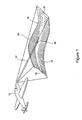
- Figure 1 shows a representation of an aircraft 10 that is equipped with a forward-looking sensor such as a forward-looking infrared (FLIR) sensor or a synthetic aperture radar (SAR) sensor.
- a forward-looking sensor such as a forward-looking infrared (FLIR) sensor or a synthetic aperture radar (SAR) sensor.
- FLIR forward-looking infrared
- SAR synthetic aperture radar
- the drawing figure depicts the aircraft sensor having a line of sight 12 that is directed to a geographic area 14 and intersects with the terrain of the geographic area 14 at a particular point 16.
- Known sensors of this type are capable of sensing the contours of the land and/or objects within predefined boundaries of the geographic area or location 14 represented by the perimeter edge 18 shown in Figure 1.
- the sensor provides signals to the electronics of the aircraft 10 that produce a visual display (not shown) and recorded array (not shown) of the sensed image of the location 14 around the line of sight 16 within the sensed image boundaries 18.
- This visual display and the recorded array are a perspective image which depicts the land and objects in the scene around the point 16 being viewed by the sensor.
- the viewing conditions such as aircraft 10 location and orientation, and line of sight 12 direction, and location of the particular point 16 within the geographic area 14, and properties of the sensor, such as field of view and any image formation characteristics peculiar to the sensor, are expected to be known, in order that the perspective geocoordinate array for that perspective image can be constructed as this invention describes.
- the method of the construction is depicted in the flow chart of Figures 6-8.
- the method of this invention is also provided with a database that includes reference elevation arrays of several geographic areas or locations, including a reference elevation array of the geographic area or location 14 that is depicted in the perspective image.
- a typical reference elevation array database contains a geographically registered elevation array that depicts elevation or height information for the geographic area, in the form of a digital elevation model (DEM).
- DEM digital elevation model
- Each reference elevation array typically consists of a DEM with a plurality of rows and columns of elevation measures over a geographic area or location, where the row and column indices of the array have been put into mathematical correspondence with a geographic coordinate system for the area, such as the World Geodetic System 1984, or WGS84.
- the correspondence is such that each array element's location in a row and column of the digital image may be associated with a specific geographic coordinate, such as latitude and longitude in the geographic coordinate system.
- the correspondence operates in reverse, also, so that any geographic coordinate may be associated with an element's row and column location in the reference image.
- the mathematical relationship of elevation array element row and column locations to a geographic system is normally much more coarse for the DEM than for a perspective image, due to differences in the corresponding geographic spacing of the pixels and elevation measurements in the elevation array.
- pixels in a perspective image will usually have small corresponding geographic spacing, perhaps representing a ground resolution of 3.5 meters or less ground spacing between pixels, for images originating with a SPOT satellite reference image.
- DEM elevation array elements are normally more widely spaced in corresponding ground coordinates, such as 30 meter spacing for a United States Geodetic Service Level II DEM.
- the elevation measurements in the reference elevation array are then resampled by approximation, to increase or decrease the spacing of measurements to best correspond to the estimated ground coordinate spacing of pixels in the perspective image.
- the estimated ground spacing is obtained by standard geometrical calculation, based on a known range from sensor to scene, known characteristics of the sensor such as width of field of view and the incremental width of field of view for a single sensing element or pixel in the sensor, and known sensor resolution at the center of the perspective image. Resolution is measured across the direction of the line of sight as it falls on the ground to obtain best accuracy.
- Resampling is performed by establishing a grid of points covering the scene area as an array of geographic locations, with columns of points in the array running parallel to the line of sight of the sensor when projected on a plane of constant height running through the scene, and rows of points in the array running perpendicular to the line of sight of the sensor when projected on a plane of constant height running through the scene.
- Each of these points is given a known two dimensional geographic coordinate, according to its position in a row and column of the array, using the mathematical correspondence similar to that for a DEM to relate row and column indices to geographic coordinates, except that the rows and columns are aligned with the perspective image sensor line of sight, rather than with North for the typical DEM.
- an elevation measurement is approximated, by interpolation using a standard interpolation resampling means.
- the row and column indices of that grid point are used to determine corresponding geographic coordinate location for that grid point.
- the reversed correspondence of the DEM is then used to determine a fraction index location in the DEM.
- the interpolation is then done using a weighting means, based on distance from the fraction array location corresponding to the grid point to the four or more mutually adjacent posts in the DEM.
- the latitude, longitude, and elevation information for each resampled reference elevation array element is given to an appropriate accuracy.
- the accuracy figure may be retained, for use in estimating accuracy in positional calculations to be carried out in applications using the perspective image.
- DEM information is available from sources such as the United States Geological Surveys (USGS) or the National Emergency Management Association (NEMA), as well as other, Government or commercial sources.
- a region of interest is first selected from the reference elevation array.
- the region of interest is a rectangular sub-array of rows and columns from the DEM, with sub-array rows chosen to all have the same extent and to encompass all the across line of sight extent of the depicted geographic area, and with sub-array columns chosen to all have the same extent and to encompass all the along line of sight extent of the depicted geographic area.
- the rows and columns of the sub-array are aligned with the rows and columns of the DEM, respectively, and the sub-array surrounds the known location of the center of the sensor image view, or the location of the intersection 16 of the sensor image line of sight 12 with the geographic area 14.
- the location of the intersection 16 of the sensor image line of sight 12 with the geographic area 14 should be known precisely, in order that the geocoding of the perspective image be accurate, so that geocoordinates associated with each different pixel in the perspective image will accurately represent the geocoordinates of the point in the scene depicted in each of those pixels.
- this precise knowledge might be obtained by constructing a synthetic perspective image at the same time as the geocoding is constructed, so that both represent the same common perspective.
- the synthetic perspective image could be constructed by the method disclosed in my copending patent application Serial No. 11/174,036, which is incorporated herein by reference.
- the region of interest of the reference elevation array is then rotated to the previously known azimuth of the perspective image view.
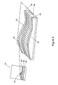
- This orientation of the reference image 22 is represented in Figure 2.
- the reference elevation array is oriented so that it is in alignment within less than 1.5 degrees relative to the orientation of the geographic area 14 as depicted in the perspective image for the aircraft image sensor line of sight 12.
- latitude and longitude position information of the aircraft image sensor which obtained the perspective image, as well as altitude information, compass heading information, and pitch and yaw information for the aircraft image sensor are used to adjust the orientation of the reference elevation array 22.
- the reference elevation array 22 is cropped or reduced in size prior to being oriented, so that only the portion of the reference elevation array needed is oriented and to reduce the computational work load.
- the reference elevation array 22 may also be resampled prior to being oriented, to a ground sample resolution or geographic spacing on the ground that better matches the ground sample resolution of the perspective image, in order to further reduce the computation work load, in the case of sampling to lower resolution, or to improve the fidelity of the synthetic perspective image, in the case of sampling to higher resolution.
- the reference elevation array 22 would be resampled to the ground sample resolution of the center pixel in the perspective image, measured along the row direction or along the direction of a line in a horizontal plane of the sensed scene perpendicular to the sensor line of sight 12 if the sensor image is rotated about the line of sight.
- the measured ground sample resolution of the perspective image may alternatively be taken as the smaller of the ground sample resolutions along the center row or along the center column of the sensor image.
- the order and nature of cropping the reference elevation array, resampling the reference elevation array, and rotating the reference elevation array to the orientation of the perspective image sensor line of sight 12 is adjusted to minimize the amount of elevation information to process. Resampling may be done first, if it reduces the number of elevation array elements that must be processed. Some cropping of the reference elevation array before its rotation is usually desirable, to eliminate processing array elements in the reference elevation array which will represent locations not visible in the perspective image, and hence need not be included in the rotation of the reference elevation array. A second cropping of the reference elevation array following its rotation is also possible, to reduce the computational burden of unneeded array element processing in generating the perspective image geocoding.
- the perspective geocoordinate array 24 is generated in a forward-mapping procedure which solves the hidden surface problem in a way that provides sufficient speed and adequate quality in generating the perspective geocoordinate array from standard reference elevation arrays that are selected corresponding to the sensor parameters of the aircraft 10 or other sensor that obtained the perspective image.
- the perspective geocoordinate array 24 is generated by mapping the cropped and oriented reference elevation array 22 into the perspective geocoordinate array 24.
- the reference elevation array 22 is mapped to the perspective geocoordinate array 24 from foreground to background of the location area 14, or from the bottom of the elevation array to the top of the elevation array, row by row, and within rows, element-by-element, using the surface elevation measurement associated with each row and column index of the reference elevation array 22 in order to properly map array elements into locations in bottom to top order. This ordering is crucial to ensuring that foreground objects at higher elevations obscure background objects at lower elevations in the generated perspective geocoordinate array 24.
- a geocoordinate value consisting of the X and Y geocoordinate values associated with the row and column indices of the reference elevation array element location in the reference elevation array, together with the elevation or Z value stored in that element of the reference elevation array, are stored as the geocoordinate value in the mapped element in the perspective geocoordinate array.
- the generated perspective elevation array element values are blurred downward and to the sides in the perspective geocoordinate array 24, to provide complete filling of the generated perspective geocoordinate array elements, and assure assignment of values to all elements in the perspective geocoordinate array.
- Figure 2 represents the manner in which the reference elevation array 22 is processed or used to generate the perspective geocoordinate array 24 by mapping each element 32 of the reference elevation array 22 individually into an element 34 in the perspective geocoordinate array 24. This is accomplished by using a standard projection coordinate transform known in the art for mapping locations from a three-dimensional scene into a two-dimensional image plane, and which corresponds accurately with the projection means that formed the perspective image.
- Figure 2 shows the rows 36 and columns 38 of the reference elevation array elements in the three-dimensional reference elevation array where each element of the reference elevation array retains a Z-component for the height or elevation value associated with the reference elevation array element.
- the row and column indices of the array element 32 are assigned X-component and Y-component values to complete the three-dimensional geocoordinate.
- the X-component and Y-component values are obtained using the correspondence to geocoordinates for row and column indices from the resampled reference elevation array.
- the information provided by the resampled elevation array is used as the Z-component in the perspective image transformation, so that the perspective geocoordinate array 24 is given an accurate rendering of the perspective geometry of the geographic area or location 14.
- the particular standard transformation employed in generating the perspective geocoordinate array 24 may be modified, or an additional transformation included, to adjust for sensor-specific geometric distortions that occur in the perspective image. These modifications that accommodate for known distortions in particular types of sensors are known in the art.
- a front row or bottom row 42 of the reference elevation array elements is first mapped into a front line or bottom line 44 of the perspective geocoordinate array element with the geocoordinate value associated with each reference elevation array element being assigned to the mapped perspective geocoordinate array element.
- the line of elements 44 in the perspective geocoordinate array 24 mapped from a row of elements 42 in the reference elevation array 22 will follow a path through the perspective geocoordinate array 24 that depends on the elevations stored in the elements in the row of elements 42 in the reference elevation array 22.
- Successive rows 36 of the reference elevation array elements extending upwardly across the reference elevation array 22 are then mapped to successive lines 40 of perspective geocoordinate array elements upwardly across the perspective geocoordinate array 24.
- the placement in row and column locations of successive lines 40 of the perspective geocoordinate array elements depends on the elevation measurements in the elements in the successive rows of reference elevation array elements 36 mapped to each line 40 of perspective geocoordinate array elements.
- a line 40 of perspective geocoordinate array elements may cross a previously mapped line, indicating low elevations mapped from the current row 36 of reference elevation array elements are obscured by higher elevations closer to the perspective image sensor, mapped from a previously mapped row of reference elevation array elements, and resulting in some elements 34 in the succeeding line of the perspective geocoordinate array 24 not being retained.
- the lines 40 of elements in the perspective geocoordinate array 24 may come closer together or spread farther apart, indicating differing changes in elevations between the rows 36 of elements in the reference elevation array 22.
- the top or back row 46 of the reference elevation array elements is last mapped to a top or back line 48 of the perspective geocoordinate array elements, completing the generation of the perspective geocoordinate array 24 of the sensed location depicted in the perspective image.
- the perspective geocoordinate array so completed is now rotated using standard image rotation means to conform to the rotation known for the perspective image.
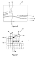
- a novel aspect of the invention is the complete filling of the geocoordinate array space in the perspective geocoordinate array 24.
- a forward transform, as used here in mapping the individual reference elevation array elements 32 from the reference elevation array 22 to perspective geocoordinate array elements 34 of the perspective geocoordinate array 24, will typically not completely fill the perspective geocoordinate array 24. This means some perspective geocoordinate array elements 34 will not be mapped with a reference elevation array element 32. Completing the perspective geocoordinate array by filling in unmapped geocoordinate elements is an important step in creating a useful perspective geocoordinate array.
- the novel method employed with the invention to determine values for perspective geocoordinate array elements whose values were not determined by the direct projection or mapping from the three-dimensional reference elevation array elements, requires processing the reference elevation array elements 32 by rows 36, from the closest or bottommost reference elevation array row 42 successively across the reference elevation array to the farthest or top reference elevation array row 46. As each reference elevation array row 36 is processed, it is known thereby that all closer rows of the reference elevation array elements have already been processed.
- a reference elevation array element 32 is projected into an array location in the perspective geocoordinate array 24 that has already been assigned or mapped a reference elevation array element value, it is known that the reference elevation array element being mapped is occluded or hidden from view from the viewpoint of the perspective image sensor of the aircraft 10 and cannot be seen in the perspective image 24, and should not be represented in the perspective geocoordinate array, so that reference elevation array element is processed no further. If a reference elevation array element 32 is projected into an element location in the perspective geocoordinate array 24 that has not been previously assigned a value, then the reference elevation array element is visible and its value is assigned to the perspective geocoordinate array element 34 into which it is projected.
- the geocoordinate value assigned to the mapped perspective geocoordinate array element 52 is used to assign a geocoordinate value to any perspective geocoordinate array element in the column 54 below the mapped perspective geocoordinate array element 52, which has not previously been mapped by a reference elevation array element and not previously been assigned a geocoordinate value. It is important that the backfill be done for each row as the row is projected, and as each element is projected, else some later projected element be mapped into an unfilled element that would have been filled if the filling had been done as each element was initially mapped.
- This backfilling technique is to ensure that no elements of the perspective geocoordinate array lacking an assigned geocoordinate value will be left surrounded by pixels having assigned geocoordinate values in the completed perspective geocoordinate array. Any elements in the perspective geocoordinate array 24 that are below the mapped perspective geocoordinate array element 52 and that have not been previously mapped, come from or correspond to closer locations in the reference scene area. Hence, if the perspective geocoordinate array elements in the column 54 below the mapped perspective geocoordinate array element 52 have not been assigned geocoordinate values, those lower, unassigned elements of the column 54 should be given the geocoordinate value of closer elements from the reference elevation array.
- any remaining, unassigned elements in that column 54 and beneath the mapped perspective geocoordinate array element 52 in the perspective geocoordinate array 24 are determined to be related to that presently mapped perspective geocoordinate array element 52.
- the geocoordinate values assigned to the lower perspective geocoordinate array elements in the column 54 are copied from the mapped element 52, when it is known that the last (or uppermost) assigned perspective geocoordinate element 56 below the presently mapped perspective geocoordinate array element 52 in that column came from other than the next closest row of elements in the reference elevation array 22.
- the geocoordinate values assigned to perspective geocoordinate array elements in that column 54 below the presently mapped perspective geocoordinate array element 52 and above the last (or uppermost) assigned perspective geocoordinate array element 56 should be determined by interpolating between the geocoordinate value of the last (or uppermost) assigned perspective geocoordinate array element 56 and the geocoordinate value of the presently mapped perspective geocoordinate array element 52, using an interpolation means such as linear interpolation.
- Successive reference elevation array elements 32 from a given row 36 of the reference elevation array also may or may not map onto perspective geocoordinate array elements 34 in successive columns 54 in the perspective geocoordinate array as shown in Figure 4. This will typically occur if the reference elevation array 22 has a lower spatial resolution when projected to the perspective geocoordinate array 24, than the perspective image of the projected area 24 presents, as may be the case in the foreground or lower areas of the perspective geocoordinate array 24. This is another aspect of the lack of mapped coverage in the perspective geocoordinate array 24 that may arise in the projection of reference elevation array elements 32 from the reference elevation array 22 to the perspective geocoordinate array 24.
- the novel method to complete mapped coverage in this situation is to interpolate spatially to the sides, to neighboring columns 54, that is, to interpolate unmapped perspective geocoordinate array elements in a row 58 of the perspective geocoordinate array between the two successively mapped geocoordinate array elements 62, 64 across the columns of the perspective geocoordinate array, and to treat the intermediate interpolated perspective geocoordinate array elements 66 as individually mapped elements.
- its assigned geocoordinate value is copied or interpolated down its column 68 to the last (or uppermost) perspective geocoordinate array element 72 below it which was previously assigned a geocoordinate value, as if element 66 had actually been mapped from the reference elevation array 22.
- the spatial interpolation between the current 64 and preceding 62 mapped perspective geocoordinate array elements can be accomplished by any reasonable interpolation means, such as the Brezenham blind interpolation algorithm, a known prior art algorithm, and may proceed in any order, such as from the current perspective geocoordinate array element 64 to a preceding mapped perspective geocoordinate array element 62, or the reverse.
- any reasonable interpolation means such as the Brezenham blind interpolation algorithm, a known prior art algorithm, and may proceed in any order, such as from the current perspective geocoordinate array element 64 to a preceding mapped perspective geocoordinate array element 62, or the reverse.
- the present perspective geocoordinate array element 64 and the preceding mapped perspective geocoordinate array element 62 may have different row and column positions, or either or both could be the same, so that the interpolation may not be a simple sequencing along a row or column, but will generally sequence on an angular, stepped path through the perspective geocoordinate array as shown in Figure 4 for interpolation from a currently mapped element 52 of the perspective geocoordinate array 24 to the last preceding currently mapped element 62, both of which came from the same row 36 of elements in the reference elevation array, and from adjacent elements in that row.
- Intermediate mapped perspective geocoordinate array elements 66 so interpolated in this line of elements in the perspective geocoordinate array should be assigned interpolated geocoordinate values determined proportionally and separately for each X, Y and Z component of the geocoordinate values, from the current mapped element 54 to the last preceding currently mapped element 62, or in the reverse direction, for best accuracy, where the geocoordinate value interpolation means may be an extension of the location interpolation means, or a separate interpolation means.
- these elements 52 through 62 should be treated each as a mapped element, and any unmapped elements in the columns 54 beneath them in the perspective geocoordinate array should be back filled in the manner described above.
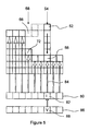
- FIG. 5 Another novel aspect of the invention, depicted in Figure 5, gives increased efficiency of interpolation down a column of perspective geocoordinate array elements 54 from the currently mapped perspective geocoordinate array element 52 to the last previously mapped perspective geocoordinate array element 56 in that column 54. It utilizes a row index array 80 of row index values 82, one for each column of elements 54 in the perspective geocoordinate array, to indicate 84 where in the column 54 the last previously mapped perspective geocoordinate array element was mapped, and thus to also indicate how far down it is necessary to interpolate in that column.
- the row index value I in the row index array location 82 corresponding to a column 54 is the row index of the last previously mapped or horizontally interpolated element 56 in that column.
- a similar geocoordinate value array 86 of geocoordinate values X, Y and Z shown as V 88 is used to hold corresponding geocoordinate values of the last previously mapped perspective geocoordinate array element 56 for each column 54. Interpolation down a column 54 of perspective geocoordinate array elements can then be easily done without checking if elements have been assigned a geocoordinate value, as the interpolation proceeds from the row position of the currently mapped element 52 to the row position above the row indexed 82 in the row index array 80 for that column 54 containing the last previously mapped element 56.
- This use of the row index array also eliminates any need to interpret one geocoordinate value as a sentinel value, to indicate when no value has yet been assigned to a geocoordinate value storage element, allowing fullest use of element values to hold geocoordinate values, which could be encoded or compressed more readily in the absence of a need for a sentinel value. Interpolation is then done using the geocoordinate value of the currently mapped element 52 and, when appropriate, the geocoordinate value 88 obtained from the geocoordinate value array 86 of the last mapped element 56 in that column 54, according to the previously described interpolation means.
- the row index value for the currently mapped perspective geocoordinate array element 52 is copied into the row index array location 82 corresponding to that column 54 of perspective geocoordinate array, replacing the value that was there, and the geocoordinate value of the currently mapped perspective geocoordinate array element 52 is copied into the geocoordinate value array location 88 corresponding to that column 54 of perspective geocoordinate array, replacing the value that was there.
- the geocodes may be represented in more than one way, and usually, the two geocode arrays involved will represent the geocodes differently.
- the "geocode” could also include non-geographic, 3-D coordinate systems.
- the location geocode array normally has a simple relation to a planar orthogonal coordinate system. This might be geographic longitude and latitude, or it might be meters North and meters East in a UTM map coordinate system, or it might be meters units in two orthogonal coordinate axes of a model coordinate system for the scene. The axes don't actually have to be orthogonal; however orthogonal axes makes the coordinate transforms easier.
- a simple relation may be a set of two linear transforms (scale and offset) that transform one row or column coordinate of the array into one of the location coordinates.
- row coordinates might transform into latitude values
- column coordinates might transform into longitude values.
- the row and column index pair might transform into a pair of longitude and latitude values, under a two dimensional linear transform.
- Such simple transforms are invertible, so the location geocode value can be transformed (by the inverse transform) into corresponding row and column indices.
- the third geocode coordinate falls on a coordinate axis that is usually orthogonal to both of the other two axes, such as the way altitude is related to longitude and latitude.
- the location geocode array is best presented as an array of third coordinate values only (e.g. altitude values) where the row and column array coordinates (indices) have a simple relation to the first two location coordinate values.
- each location geocode value is represented at a location in the array by (i) the row and column position in the array, which directly relates to the planar two dimensional position, and (ii) the value stored at that position in the array, the third coordinate.
- the row and column index of a geocode value in the location geocode array represent longitude and latitude coordinates, and the value stored is the elevation coordinate.
- the situation is different. It may or may not be feasible to use the row and column indices of those image geocode values to simply translate into two of the three location geocode values.
- a projection transform is used to map a three dimensional location geocode (longitude, latitude, altitude) to a two dimensional (row and column) pixel location in the image. This row and column location is the same as for the image geocode value for that pixel, but the inverse of a projective transform can not produce three coordinates from only two coordinates, it requires the use of all three image geocode coordinates.
- the inverse projection may be performed using the row index and column index values, and a value at that row and column location, if the proper value is stored at that location. What the proper value is depends on the type of projection, and may involve a more difficult computation to determine the location geocode that was originally mapped to that image geocode location. This particularly becomes a difficulty under the backfill method of the invention.
- a simpler, approach is to simply record the complete location geocode coordinate set of three values in the image geocode location mapped when the location geocode coordinates were projected to the image array.
- An equivalent approach is to record the location geocode row and column array index coordinates, and the the third location coordinate.
- the row and column index coordinates usually require less computer storage, making this method more efficient in use of storage.
- the image geocode value is clearly a location geocode.
- the value in a location geocode array element is an altitude value, while the position of that value in the array represents the other two coordinates of the location geocode. It is necessary to distinguish the two different arrays of geocodes, because the projection maps location geocodes to image pixel locations, and the location geocode is stored into that image pixel's associated image geocode.
- backfilling and sidemapping are systems that they must be done incrementally, as each new location geocode is mapped to an image pixel.
- the mapping order is important.
- the mapping of geographic coordinates to pixels must operate to first map the row of geocoordinates that are closest to the sensor's geographic location when the image was obtained, then successive rows of geocoordinates that each fall farther than the last from the sensor's location, and finally the row of geocoordinates that are farthest from the sensor's geographic location.
- the reference array of geocodes (that is, of geographic coordinates, or the elevation values in the array for which the row and column addresses in the array are associated with longitude and latitude coordinates of the area around the location seen in the image) is rotated to achieve this particular orientation, that is, so there will be a row of geographic coordinates closest to the sensor's location, and the direction of that row will be perpendicular to the direction of the sensor's line of sight.
- This orientation is important, as it makes the projection come out right.
- mapping of rows of geocodes to the image pixel array is then to lines of pixels in the image that are not necessarily rows of pixels nor necessarily straight lines. Only in general will those lines proceed from the bottom of the image to the top. With variation in the elevation values, the lines of pixels so mapped can be wavy. They will, however, not have loops, because the elevation in the location area can not have overhangs. (Such might exist in nature, but the geographic information will only show the highest part of an overhang.)
- mapping has only an incidental relation to pixel locations, but is fully dependent on the location geocode order.
Landscapes
- Engineering & Computer Science (AREA)
- Physics & Mathematics (AREA)
- General Physics & Mathematics (AREA)
- Remote Sensing (AREA)
- Software Systems (AREA)
- Geometry (AREA)
- Computer Graphics (AREA)
- Theoretical Computer Science (AREA)
- Multimedia (AREA)
- Radar, Positioning & Navigation (AREA)
- Image Processing (AREA)
- Processing Or Creating Images (AREA)
- Analysing Materials By The Use Of Radiation (AREA)
- Adornments (AREA)
Priority Applications (1)
| Application Number | Priority Date | Filing Date | Title |
|---|---|---|---|
| EP09165211.5A EP2103903B1 (de) | 2005-11-22 | 2006-11-20 | Verfahren zur Geocodierung eines perspektivischen Bildes |
Applications Claiming Priority (1)
| Application Number | Priority Date | Filing Date | Title |
|---|---|---|---|
| US11/285,248 US7873240B2 (en) | 2005-07-01 | 2005-11-22 | Method for analyzing geographic location and elevation data and geocoding an image with the data |
Related Child Applications (1)
| Application Number | Title | Priority Date | Filing Date |
|---|---|---|---|
| EP09165211.5A Division EP2103903B1 (de) | 2005-11-22 | 2006-11-20 | Verfahren zur Geocodierung eines perspektivischen Bildes |
Publications (3)
| Publication Number | Publication Date |
|---|---|
| EP1788349A2 true EP1788349A2 (de) | 2007-05-23 |
| EP1788349A3 EP1788349A3 (de) | 2007-07-11 |
| EP1788349B1 EP1788349B1 (de) | 2010-01-06 |
Family
ID=37762100
Family Applications (2)
| Application Number | Title | Priority Date | Filing Date |
|---|---|---|---|
| EP06077050A Active EP1788349B1 (de) | 2005-11-22 | 2006-11-20 | Geokodierungsverfahren eines perspektivischen Bildes |
| EP09165211.5A Active EP2103903B1 (de) | 2005-11-22 | 2006-11-20 | Verfahren zur Geocodierung eines perspektivischen Bildes |
Family Applications After (1)
| Application Number | Title | Priority Date | Filing Date |
|---|---|---|---|
| EP09165211.5A Active EP2103903B1 (de) | 2005-11-22 | 2006-11-20 | Verfahren zur Geocodierung eines perspektivischen Bildes |
Country Status (4)
| Country | Link |
|---|---|
| US (1) | US7873240B2 (de) |
| EP (2) | EP1788349B1 (de) |
| AT (1) | ATE454606T1 (de) |
| DE (1) | DE602006011562D1 (de) |
Cited By (1)
| Publication number | Priority date | Publication date | Assignee | Title |
|---|---|---|---|---|
| CN105571570A (zh) * | 2016-01-07 | 2016-05-11 | 中国科学院遥感与数字地球研究所 | 一种航空摄影外业的方法及装置 |
Families Citing this family (37)
| Publication number | Priority date | Publication date | Assignee | Title |
|---|---|---|---|---|
| US8055100B2 (en) * | 2004-04-02 | 2011-11-08 | The Boeing Company | Method and system for image registration quality confirmation and improvement |
| US20070253639A1 (en) * | 2006-05-01 | 2007-11-01 | The United States Of America As Represented By The Secretary Of The Navy | Imagery analysis tool |
| US20070257903A1 (en) * | 2006-05-04 | 2007-11-08 | Harris Corporation | Geographic information system (gis) for displaying 3d geospatial images with reference markers and related methods |
| BRPI0606106B1 (pt) * | 2006-11-28 | 2018-02-14 | Fundação Oswaldo Cruz | Método para criar uma imagem em perspectiva, e, uso do método |
| US7865285B2 (en) * | 2006-12-27 | 2011-01-04 | Caterpillar Inc | Machine control system and method |
| US8253797B1 (en) * | 2007-03-05 | 2012-08-28 | PureTech Systems Inc. | Camera image georeferencing systems |
| EP2172031A1 (de) * | 2007-07-04 | 2010-04-07 | Saab AB | Anordnung und verfahren zum bereitstellen einer dreidimensionalen kartendarstellung eines gebiets |
| US8095249B2 (en) * | 2007-09-04 | 2012-01-10 | Honeywell International Inc. | System and method for displaying a digital terrain |
| US8121433B2 (en) * | 2008-01-18 | 2012-02-21 | California Institute Of Technology | Ortho-rectification, coregistration, and subpixel correlation of optical satellite and aerial images |
| EP2356584B1 (de) * | 2008-12-09 | 2018-04-11 | Tomtom North America, Inc. | Verfahren zum erzeugen eines geodetischen referenzdatenbankprodukts |
| WO2010085822A2 (en) * | 2009-01-26 | 2010-07-29 | Shotspotter, Inc. | Systems and methods with improved three-dimensional source location processing including constraint of location solutions to a two-dimensional plane |
| US8331611B2 (en) * | 2009-07-13 | 2012-12-11 | Raytheon Company | Overlay information over video |
| EP2583060A4 (de) * | 2010-06-18 | 2014-04-09 | Saab Ab | Verfahren zur zielortung und system zur zielortung |
| US20120092348A1 (en) * | 2010-10-14 | 2012-04-19 | Immersive Media Company | Semi-automatic navigation with an immersive image |
| GB201100403D0 (en) * | 2011-01-11 | 2011-02-23 | Totom Dev Germany Gmbh | An efficient location referencing method |
| ES2743529T3 (es) * | 2011-11-08 | 2020-02-19 | Saab Ab | Procedimiento y sistema de determinación de una relación entre una primera escena y una segunda escena |
| US9476970B1 (en) * | 2012-03-19 | 2016-10-25 | Google Inc. | Camera based localization |
| CN103344250B (zh) * | 2013-07-05 | 2017-06-09 | 深圳市大疆创新科技有限公司 | 无人飞行器的飞行辅助方法和装置 |
| CN105493136A (zh) | 2013-07-19 | 2016-04-13 | 慧与发展有限责任合伙企业 | 具有不同程度的重叠地理编码像素的地图 |
| US20150176989A1 (en) * | 2013-12-23 | 2015-06-25 | Hti Ip, Llc | Accelerometer-Based Hill Angle Estimation |
| US9709673B2 (en) * | 2014-04-14 | 2017-07-18 | Vricon Systems Ab | Method and system for rendering a synthetic aperture radar image |
| US10802135B2 (en) | 2016-12-21 | 2020-10-13 | The Boeing Company | Method and apparatus for raw sensor image enhancement through georegistration |
| US11175398B2 (en) | 2016-12-21 | 2021-11-16 | The Boeing Company | Method and apparatus for multiple raw sensor image enhancement through georegistration |
| CN110869981B (zh) * | 2016-12-30 | 2023-12-01 | 辉达公司 | 用于自主车辆的高清晰度地图数据的向量数据编码 |
| US10509415B2 (en) * | 2017-07-27 | 2019-12-17 | Aurora Flight Sciences Corporation | Aircrew automation system and method with integrated imaging and force sensing modalities |
| US11080537B2 (en) * | 2017-11-15 | 2021-08-03 | Uatc, Llc | Autonomous vehicle lane boundary detection systems and methods |
| AU2018381377B2 (en) * | 2017-12-08 | 2021-12-09 | Asia Air Survey Co., Ltd. | Feature height-based colored image generating apparatus and feature height-based colored image generating program |
| EP3664038A1 (de) * | 2018-12-06 | 2020-06-10 | Ordnance Survey Limited | Geospatiales vermessungsinstrument |
| KR102522923B1 (ko) * | 2018-12-24 | 2023-04-20 | 한국전자통신연구원 | 차량의 자기위치 추정 장치 및 그 방법 |
| CN110765665B (zh) * | 2019-11-27 | 2024-01-26 | 武汉中地数码科技有限公司 | 一种地学动态建模方法及系统 |
| CN111983608A (zh) * | 2020-07-07 | 2020-11-24 | 西安瑞得空间信息技术有限公司 | 一种快速dem生成方法 |
| EP4036859A1 (de) * | 2021-01-27 | 2022-08-03 | Maxar International Sweden AB | System und verfahren zur bereitstellung von verbesserten geocodierten referenzdaten an eine 3d-kartendarstellung |
| CN114022594B (zh) * | 2022-01-04 | 2022-04-01 | 北京山维科技股份有限公司 | 一种斜坡类地理信息要素图形处理方法和装置 |
| FR3132777B1 (fr) * | 2022-02-11 | 2024-12-13 | Thales Sa | Système électronique d’assistance à la navigation d’un aéronef, procédé et programme d’ordinateur associés |
| CN115311396B (zh) * | 2022-08-09 | 2023-06-02 | 北京飞渡科技股份有限公司 | 一种超高建筑物屋顶轮廓线的自动提取方法及系统 |
| US12037769B1 (en) * | 2023-06-29 | 2024-07-16 | Built Robotics Inc. | Autonomous offroad vehicle path planning with collision avoidance |
| CN119879837B (zh) * | 2024-12-27 | 2025-10-17 | 西安电子科技大学 | 基于同航过多角度sar图像的海面高程测量方法及装置 |
Family Cites Families (20)
| Publication number | Priority date | Publication date | Assignee | Title |
|---|---|---|---|---|
| US4988189A (en) | 1981-10-08 | 1991-01-29 | Westinghouse Electric Corp. | Passive ranging system especially for use with an electro-optical imaging system |
| JP2531605B2 (ja) | 1984-02-24 | 1996-09-04 | 株式会社東芝 | 画像の位置合せ装置 |
| US4970666A (en) | 1988-03-30 | 1990-11-13 | Land Development Laboratory, Inc. | Computerized video imaging system for creating a realistic depiction of a simulated object in an actual environment |
| US5173949A (en) | 1988-08-29 | 1992-12-22 | Raytheon Company | Confirmed boundary pattern matching |
| US5870486A (en) | 1991-12-11 | 1999-02-09 | Texas Instruments Incorporated | Method of inferring sensor attitude through multi-feature tracking |
| US5550937A (en) | 1992-11-23 | 1996-08-27 | Harris Corporation | Mechanism for registering digital images obtained from multiple sensors having diverse image collection geometries |
| CA2114986A1 (en) | 1993-02-08 | 1994-08-09 | Robert T. Frankot | Automatic subarea selection for image registration |
| US5606627A (en) * | 1995-01-24 | 1997-02-25 | Eotek Inc. | Automated analytic stereo comparator |
| JP3375258B2 (ja) | 1996-11-07 | 2003-02-10 | 株式会社日立製作所 | 地図表示方法及び装置並びにその装置を備えたナビゲーション装置 |
| US6512857B1 (en) * | 1997-05-09 | 2003-01-28 | Sarnoff Corporation | Method and apparatus for performing geo-spatial registration |
| US6597818B2 (en) * | 1997-05-09 | 2003-07-22 | Sarnoff Corporation | Method and apparatus for performing geo-spatial registration of imagery |
| US5995681A (en) | 1997-06-03 | 1999-11-30 | Harris Corporation | Adjustment of sensor geometry model parameters using digital imagery co-registration process to reduce errors in digital imagery geolocation data |
| AU9783798A (en) | 1997-10-06 | 1999-04-27 | John A. Ciampa | Digital-image mapping |
| US6266452B1 (en) | 1999-03-18 | 2001-07-24 | Nec Research Institute, Inc. | Image registration method |
| US6694064B1 (en) * | 1999-11-19 | 2004-02-17 | Positive Systems, Inc. | Digital aerial image mosaic method and apparatus |
| US6738532B1 (en) | 2000-08-30 | 2004-05-18 | The Boeing Company | Image registration using reduced resolution transform space |
| US6795590B1 (en) | 2000-09-22 | 2004-09-21 | Hrl Laboratories, Llc | SAR and FLIR image registration method |
| US20040041999A1 (en) * | 2002-08-28 | 2004-03-04 | Hogan John M. | Method and apparatus for determining the geographic location of a target |
| US20050147324A1 (en) | 2003-10-21 | 2005-07-07 | Kwoh Leong K. | Refinements to the Rational Polynomial Coefficient camera model |
| US7751651B2 (en) | 2004-04-02 | 2010-07-06 | The Boeing Company | Processing architecture for automatic image registration |
-
2005
- 2005-11-22 US US11/285,248 patent/US7873240B2/en active Active
-
2006
- 2006-11-20 DE DE602006011562T patent/DE602006011562D1/de active Active
- 2006-11-20 AT AT06077050T patent/ATE454606T1/de not_active IP Right Cessation
- 2006-11-20 EP EP06077050A patent/EP1788349B1/de active Active
- 2006-11-20 EP EP09165211.5A patent/EP2103903B1/de active Active
Cited By (2)
| Publication number | Priority date | Publication date | Assignee | Title |
|---|---|---|---|---|
| CN105571570A (zh) * | 2016-01-07 | 2016-05-11 | 中国科学院遥感与数字地球研究所 | 一种航空摄影外业的方法及装置 |
| CN105571570B (zh) * | 2016-01-07 | 2018-01-12 | 中国科学院遥感与数字地球研究所 | 一种航空摄影外业的方法及装置 |
Also Published As
| Publication number | Publication date |
|---|---|
| DE602006011562D1 (de) | 2010-02-25 |
| ATE454606T1 (de) | 2010-01-15 |
| EP2103903A2 (de) | 2009-09-23 |
| EP2103903A3 (de) | 2009-09-30 |
| EP2103903B1 (de) | 2019-01-09 |
| US20070002040A1 (en) | 2007-01-04 |
| EP1788349A3 (de) | 2007-07-11 |
| US7873240B2 (en) | 2011-01-18 |
| EP1788349B1 (de) | 2010-01-06 |
Similar Documents
| Publication | Publication Date | Title |
|---|---|---|
| EP2103903B1 (de) | Verfahren zur Geocodierung eines perspektivischen Bildes | |
| US7580591B2 (en) | Method for generating a synthetic perspective image | |
| CA2395257C (en) | Any aspect passive volumetric image processing method | |
| CA2705809C (en) | Method and apparatus of taking aerial surveys | |
| US8107722B2 (en) | System and method for automatic stereo measurement of a point of interest in a scene | |
| Al-Rousan et al. | Automated DEM extraction and orthoimage generation from SPOT level 1B imagery | |
| US8139111B2 (en) | Height measurement in a perspective image | |
| US8098958B2 (en) | Processing architecture for automatic image registration | |
| US20060215935A1 (en) | System and architecture for automatic image registration | |
| KR20090064679A (ko) | 이종 센서 통합 모델링에 의한 수치 사진 측량 방법 및장치 | |
| AU2013260677B2 (en) | Method and apparatus of taking aerial surveys | |
| Paar et al. | Preparing 3D vision & visualization for ExoMars | |
| Niu et al. | Geometric modeling and processing of QuickBird stereo imagery | |
| CN118379453A (zh) | 一种无人机航拍影像与webGIS三维场景联动交互方法及系统 | |
| WO2009042933A1 (en) | Photogrammetric networks for positional accuracy and ray mapping |
Legal Events
| Date | Code | Title | Description |
|---|---|---|---|
| PUAI | Public reference made under article 153(3) epc to a published international application that has entered the european phase |
Free format text: ORIGINAL CODE: 0009012 |
|
| AK | Designated contracting states |
Kind code of ref document: A2 Designated state(s): AT BE BG CH CY CZ DE DK EE ES FI FR GB GR HU IE IS IT LI LT LU LV MC NL PL PT RO SE SI SK TR |
|
| AX | Request for extension of the european patent |
Extension state: AL BA HR MK YU |
|
| PUAL | Search report despatched |
Free format text: ORIGINAL CODE: 0009013 |
|
| AK | Designated contracting states |
Kind code of ref document: A3 Designated state(s): AT BE BG CH CY CZ DE DK EE ES FI FR GB GR HU IE IS IT LI LT LU LV MC NL PL PT RO SE SI SK TR |
|
| AX | Request for extension of the european patent |
Extension state: AL BA HR MK YU |
|
| 17P | Request for examination filed |
Effective date: 20070719 |
|
| 17Q | First examination report despatched |
Effective date: 20070907 |
|
| AKX | Designation fees paid |
Designated state(s): AT BE BG CH CY CZ DE DK EE ES FI FR GB GR HU IE IS IT LI LT LU LV MC NL PL PT RO SE SI SK TR |
|
| GRAP | Despatch of communication of intention to grant a patent |
Free format text: ORIGINAL CODE: EPIDOSNIGR1 |
|
| GRAS | Grant fee paid |
Free format text: ORIGINAL CODE: EPIDOSNIGR3 |
|
| GRAA | (expected) grant |
Free format text: ORIGINAL CODE: 0009210 |
|
| AK | Designated contracting states |
Kind code of ref document: B1 Designated state(s): AT BE BG CH CY CZ DE DK EE ES FI FR GB GR HU IE IS IT LI LT LU LV MC NL PL PT RO SE SI SK TR |
|
| REG | Reference to a national code |
Ref country code: GB Ref legal event code: FG4D |
|
| REG | Reference to a national code |
Ref country code: CH Ref legal event code: EP |
|
| REG | Reference to a national code |
Ref country code: IE Ref legal event code: FG4D |
|
| REF | Corresponds to: |
Ref document number: 602006011562 Country of ref document: DE Date of ref document: 20100225 Kind code of ref document: P |
|
| REG | Reference to a national code |
Ref country code: NL Ref legal event code: VDEP Effective date: 20100106 |
|
| PG25 | Lapsed in a contracting state [announced via postgrant information from national office to epo] |
Ref country code: SI Free format text: LAPSE BECAUSE OF FAILURE TO SUBMIT A TRANSLATION OF THE DESCRIPTION OR TO PAY THE FEE WITHIN THE PRESCRIBED TIME-LIMIT Effective date: 20100106 |
|
| LTIE | Lt: invalidation of european patent or patent extension |
Effective date: 20100106 |
|
| PG25 | Lapsed in a contracting state [announced via postgrant information from national office to epo] |
Ref country code: AT Free format text: LAPSE BECAUSE OF FAILURE TO SUBMIT A TRANSLATION OF THE DESCRIPTION OR TO PAY THE FEE WITHIN THE PRESCRIBED TIME-LIMIT Effective date: 20100106 |
|
| PG25 | Lapsed in a contracting state [announced via postgrant information from national office to epo] |
Ref country code: IS Free format text: LAPSE BECAUSE OF FAILURE TO SUBMIT A TRANSLATION OF THE DESCRIPTION OR TO PAY THE FEE WITHIN THE PRESCRIBED TIME-LIMIT Effective date: 20100506 Ref country code: LT Free format text: LAPSE BECAUSE OF FAILURE TO SUBMIT A TRANSLATION OF THE DESCRIPTION OR TO PAY THE FEE WITHIN THE PRESCRIBED TIME-LIMIT Effective date: 20100106 Ref country code: PT Free format text: LAPSE BECAUSE OF FAILURE TO SUBMIT A TRANSLATION OF THE DESCRIPTION OR TO PAY THE FEE WITHIN THE PRESCRIBED TIME-LIMIT Effective date: 20100506 Ref country code: NL Free format text: LAPSE BECAUSE OF FAILURE TO SUBMIT A TRANSLATION OF THE DESCRIPTION OR TO PAY THE FEE WITHIN THE PRESCRIBED TIME-LIMIT Effective date: 20100106 Ref country code: ES Free format text: LAPSE BECAUSE OF FAILURE TO SUBMIT A TRANSLATION OF THE DESCRIPTION OR TO PAY THE FEE WITHIN THE PRESCRIBED TIME-LIMIT Effective date: 20100417 |
|
| PG25 | Lapsed in a contracting state [announced via postgrant information from national office to epo] |
Ref country code: PL Free format text: LAPSE BECAUSE OF FAILURE TO SUBMIT A TRANSLATION OF THE DESCRIPTION OR TO PAY THE FEE WITHIN THE PRESCRIBED TIME-LIMIT Effective date: 20100106 Ref country code: LV Free format text: LAPSE BECAUSE OF FAILURE TO SUBMIT A TRANSLATION OF THE DESCRIPTION OR TO PAY THE FEE WITHIN THE PRESCRIBED TIME-LIMIT Effective date: 20100106 Ref country code: FI Free format text: LAPSE BECAUSE OF FAILURE TO SUBMIT A TRANSLATION OF THE DESCRIPTION OR TO PAY THE FEE WITHIN THE PRESCRIBED TIME-LIMIT Effective date: 20100106 |
|
| PG25 | Lapsed in a contracting state [announced via postgrant information from national office to epo] |
Ref country code: BE Free format text: LAPSE BECAUSE OF FAILURE TO SUBMIT A TRANSLATION OF THE DESCRIPTION OR TO PAY THE FEE WITHIN THE PRESCRIBED TIME-LIMIT Effective date: 20100106 Ref country code: EE Free format text: LAPSE BECAUSE OF FAILURE TO SUBMIT A TRANSLATION OF THE DESCRIPTION OR TO PAY THE FEE WITHIN THE PRESCRIBED TIME-LIMIT Effective date: 20100106 Ref country code: RO Free format text: LAPSE BECAUSE OF FAILURE TO SUBMIT A TRANSLATION OF THE DESCRIPTION OR TO PAY THE FEE WITHIN THE PRESCRIBED TIME-LIMIT Effective date: 20100106 Ref country code: CY Free format text: LAPSE BECAUSE OF FAILURE TO SUBMIT A TRANSLATION OF THE DESCRIPTION OR TO PAY THE FEE WITHIN THE PRESCRIBED TIME-LIMIT Effective date: 20100106 Ref country code: SE Free format text: LAPSE BECAUSE OF FAILURE TO SUBMIT A TRANSLATION OF THE DESCRIPTION OR TO PAY THE FEE WITHIN THE PRESCRIBED TIME-LIMIT Effective date: 20100106 Ref country code: GR Free format text: LAPSE BECAUSE OF FAILURE TO SUBMIT A TRANSLATION OF THE DESCRIPTION OR TO PAY THE FEE WITHIN THE PRESCRIBED TIME-LIMIT Effective date: 20100407 |
|
| PLBE | No opposition filed within time limit |
Free format text: ORIGINAL CODE: 0009261 |
|
| STAA | Information on the status of an ep patent application or granted ep patent |
Free format text: STATUS: NO OPPOSITION FILED WITHIN TIME LIMIT |
|
| PG25 | Lapsed in a contracting state [announced via postgrant information from national office to epo] |
Ref country code: BG Free format text: LAPSE BECAUSE OF FAILURE TO SUBMIT A TRANSLATION OF THE DESCRIPTION OR TO PAY THE FEE WITHIN THE PRESCRIBED TIME-LIMIT Effective date: 20100406 Ref country code: CZ Free format text: LAPSE BECAUSE OF FAILURE TO SUBMIT A TRANSLATION OF THE DESCRIPTION OR TO PAY THE FEE WITHIN THE PRESCRIBED TIME-LIMIT Effective date: 20100106 Ref country code: SK Free format text: LAPSE BECAUSE OF FAILURE TO SUBMIT A TRANSLATION OF THE DESCRIPTION OR TO PAY THE FEE WITHIN THE PRESCRIBED TIME-LIMIT Effective date: 20100106 |
|
| 26N | No opposition filed |
Effective date: 20101007 |
|
| PG25 | Lapsed in a contracting state [announced via postgrant information from national office to epo] |
Ref country code: DK Free format text: LAPSE BECAUSE OF FAILURE TO SUBMIT A TRANSLATION OF THE DESCRIPTION OR TO PAY THE FEE WITHIN THE PRESCRIBED TIME-LIMIT Effective date: 20100106 |
|
| PG25 | Lapsed in a contracting state [announced via postgrant information from national office to epo] |
Ref country code: IT Free format text: LAPSE BECAUSE OF FAILURE TO SUBMIT A TRANSLATION OF THE DESCRIPTION OR TO PAY THE FEE WITHIN THE PRESCRIBED TIME-LIMIT Effective date: 20100106 |
|
| PG25 | Lapsed in a contracting state [announced via postgrant information from national office to epo] |
Ref country code: MC Free format text: LAPSE BECAUSE OF NON-PAYMENT OF DUE FEES Effective date: 20101130 |
|
| REG | Reference to a national code |
Ref country code: CH Ref legal event code: PL |
|
| PG25 | Lapsed in a contracting state [announced via postgrant information from national office to epo] |
Ref country code: CH Free format text: LAPSE BECAUSE OF NON-PAYMENT OF DUE FEES Effective date: 20101130 Ref country code: LI Free format text: LAPSE BECAUSE OF NON-PAYMENT OF DUE FEES Effective date: 20101130 |
|
| REG | Reference to a national code |
Ref country code: FR Ref legal event code: ST Effective date: 20110801 |
|
| PG25 | Lapsed in a contracting state [announced via postgrant information from national office to epo] |
Ref country code: FR Free format text: LAPSE BECAUSE OF NON-PAYMENT OF DUE FEES Effective date: 20101130 Ref country code: IE Free format text: LAPSE BECAUSE OF NON-PAYMENT OF DUE FEES Effective date: 20101120 |
|
| PG25 | Lapsed in a contracting state [announced via postgrant information from national office to epo] |
Ref country code: HU Free format text: LAPSE BECAUSE OF FAILURE TO SUBMIT A TRANSLATION OF THE DESCRIPTION OR TO PAY THE FEE WITHIN THE PRESCRIBED TIME-LIMIT Effective date: 20100707 Ref country code: LU Free format text: LAPSE BECAUSE OF NON-PAYMENT OF DUE FEES Effective date: 20101120 |
|
| PG25 | Lapsed in a contracting state [announced via postgrant information from national office to epo] |
Ref country code: TR Free format text: LAPSE BECAUSE OF FAILURE TO SUBMIT A TRANSLATION OF THE DESCRIPTION OR TO PAY THE FEE WITHIN THE PRESCRIBED TIME-LIMIT Effective date: 20100106 |
|
| P01 | Opt-out of the competence of the unified patent court (upc) registered |
Effective date: 20230503 |
|
| PGFP | Annual fee paid to national office [announced via postgrant information from national office to epo] |
Ref country code: DE Payment date: 20241127 Year of fee payment: 19 |
|
| PGFP | Annual fee paid to national office [announced via postgrant information from national office to epo] |
Ref country code: GB Payment date: 20241127 Year of fee payment: 19 |