EP1788277B1 - Isolierungssystem für Trägheitsmesseinheit - Google Patents
Isolierungssystem für Trägheitsmesseinheit Download PDFInfo
- Publication number
- EP1788277B1 EP1788277B1 EP06124381A EP06124381A EP1788277B1 EP 1788277 B1 EP1788277 B1 EP 1788277B1 EP 06124381 A EP06124381 A EP 06124381A EP 06124381 A EP06124381 A EP 06124381A EP 1788277 B1 EP1788277 B1 EP 1788277B1
- Authority
- EP
- European Patent Office
- Prior art keywords
- imu
- outer ring
- isolator
- elastomer
- inner ring
- Prior art date
- Legal status (The legal status is an assumption and is not a legal conclusion. Google has not performed a legal analysis and makes no representation as to the accuracy of the status listed.)
- Expired - Fee Related
Links
Images


Classifications
-
- F—MECHANICAL ENGINEERING; LIGHTING; HEATING; WEAPONS; BLASTING
- F16—ENGINEERING ELEMENTS AND UNITS; GENERAL MEASURES FOR PRODUCING AND MAINTAINING EFFECTIVE FUNCTIONING OF MACHINES OR INSTALLATIONS; THERMAL INSULATION IN GENERAL
- F16F—SPRINGS; SHOCK-ABSORBERS; MEANS FOR DAMPING VIBRATION
- F16F15/00—Suppression of vibrations in systems; Means or arrangements for avoiding or reducing out-of-balance forces, e.g. due to motion
- F16F15/02—Suppression of vibrations of non-rotating, e.g. reciprocating systems; Suppression of vibrations of rotating systems by use of members not moving with the rotating systems
- F16F15/04—Suppression of vibrations of non-rotating, e.g. reciprocating systems; Suppression of vibrations of rotating systems by use of members not moving with the rotating systems using elastic means
- F16F15/08—Suppression of vibrations of non-rotating, e.g. reciprocating systems; Suppression of vibrations of rotating systems by use of members not moving with the rotating systems using elastic means with rubber springs ; with springs made of rubber and metal
-
- F—MECHANICAL ENGINEERING; LIGHTING; HEATING; WEAPONS; BLASTING
- F16—ENGINEERING ELEMENTS AND UNITS; GENERAL MEASURES FOR PRODUCING AND MAINTAINING EFFECTIVE FUNCTIONING OF MACHINES OR INSTALLATIONS; THERMAL INSULATION IN GENERAL
- F16F—SPRINGS; SHOCK-ABSORBERS; MEANS FOR DAMPING VIBRATION
- F16F15/00—Suppression of vibrations in systems; Means or arrangements for avoiding or reducing out-of-balance forces, e.g. due to motion
- F16F15/10—Suppression of vibrations in rotating systems by making use of members moving with the system
- F16F15/12—Suppression of vibrations in rotating systems by making use of members moving with the system using elastic members or friction-damping members, e.g. between a rotating shaft and a gyratory mass mounted thereon
- F16F15/121—Suppression of vibrations in rotating systems by making use of members moving with the system using elastic members or friction-damping members, e.g. between a rotating shaft and a gyratory mass mounted thereon using springs as elastic members, e.g. metallic springs
- F16F15/124—Elastomeric springs
- F16F15/126—Elastomeric springs consisting of at least one annular element surrounding the axis of rotation
-
- G—PHYSICS
- G01—MEASURING; TESTING
- G01C—MEASURING DISTANCES, LEVELS OR BEARINGS; SURVEYING; NAVIGATION; GYROSCOPIC INSTRUMENTS; PHOTOGRAMMETRY OR VIDEOGRAMMETRY
- G01C19/00—Gyroscopes; Turn-sensitive devices using vibrating masses; Turn-sensitive devices without moving masses; Measuring angular rate using gyroscopic effects
- G01C19/56—Turn-sensitive devices using vibrating masses, e.g. vibratory angular rate sensors based on Coriolis forces
-
- G—PHYSICS
- G01—MEASURING; TESTING
- G01P—MEASURING LINEAR OR ANGULAR SPEED, ACCELERATION, DECELERATION, OR SHOCK; INDICATING PRESENCE, ABSENCE, OR DIRECTION, OF MOVEMENT
- G01P1/00—Details of instruments
- G01P1/02—Housings
- G01P1/023—Housings for acceleration measuring devices
-
- Y—GENERAL TAGGING OF NEW TECHNOLOGICAL DEVELOPMENTS; GENERAL TAGGING OF CROSS-SECTIONAL TECHNOLOGIES SPANNING OVER SEVERAL SECTIONS OF THE IPC; TECHNICAL SUBJECTS COVERED BY FORMER USPC CROSS-REFERENCE ART COLLECTIONS [XRACs] AND DIGESTS
- Y10—TECHNICAL SUBJECTS COVERED BY FORMER USPC
- Y10T—TECHNICAL SUBJECTS COVERED BY FORMER US CLASSIFICATION
- Y10T74/00—Machine element or mechanism
- Y10T74/21—Elements
- Y10T74/2121—Flywheel, motion smoothing-type
- Y10T74/2131—Damping by absorbing vibration force [via rubber, elastomeric material, etc.]
Definitions
- the present invention relates generally to inertial measurement units (IMUs) and more particularly to attenuating shock and vibrational energy using an IMU isolator.
- IMUs inertial measurement units
- ISA inertial sensor assembly
- IMU inertial measurement unit
- An ISA typically includes inertial sensors that detect acceleration and/or rotation in three axes. Usually, three accelerometers and three rotational rate sensors are arranged with their input axes in a perpendicular relationship.
- the sensors may generally be rigidly and precisely mounted within an ISA housing along with related electronics and hardware.
- the housing of the ISA may be mounted to a container of the IMU, and the IMU may be rigidly and precisely mounted to a frame of a vehicle, such as an aircraft, missile, or other object.
- Some applications expose the IMU to extremely high dynamic environments, such as ballistic applications wherein a projectile including an IMU may be fired from a gun.
- the inertial sensors were protected to some degree from relatively low level shock and vibration through the use of vibration isolators.
- vibration isolators demand a smaller, lighter, and more durable mechanism to withstand the high acceleration, such as 20,000 g's, associated with these environments. Therefore, it may be desirable to provide a mechanism, particularly a vibration isolator, to attenuate shock and vibrational energy and having integrated features providing protection for the inertial sensors in these high dynamic applications, such as ballistic applications, to increase the performance and reliability of the inertial sensor system.
- the present invention relates generally to inertial measurement units (IMUs) and more particularly to an IMU isolator for attenuating shock and vibrational energy. See US-A-2002158390 and WO-A-9855832 for examples.
- the protruding portion is positioned at least partially within the recessed portion and may be interlocking to prevent excessive rotation of the inner ring relative to the outer ring when the IMU experiences a high rotational force.
- the illustrative IMU may include a sensor suite attached to the inner ring, the sensor suite having at least one inertial sensor, and a cover member and a base member attached to the outer ring forming a cavity for the sensor suite, the cavity defined by cavity walls.
- the elastomer may be positioned between at least one side surface of the recessed portion and at least one side surface of the protruding portion. However, in other cases, the elastomer may not be positioned between at least one side surface of the recessed portion and at least one side surface of the protruding portion.
- an isolator for an inertial measurement unit might include an outer ring having an inner surface, an inner ring having an outer surface adjacent the inner surface of the outer ring, and an elastomer situated therebetween, the elastomer covering substantially the entire height of at least a portion of the inner surface of the outer ring and substantially the entire height of at least a portion of the outer surface of the inner ring providing an elastomer-to-elastomer contact should the outer surface of the inner ring attempt to engage the inner surface of the outer ring during a shock event.
- the elastomer may extend between the outer ring and the inner ring and may have a top gap and a bottom gap between the inner ring and the outer ring.
- an isolator for an inertial measurement unit might include an outer ring having an inner surface with a recessed portion and an inner ring having an outer surface adjacent the inner surface of the outer ring, the outer surface having a protruding portion.
- the protruding portion may be interlocked with the recessed portion by positioning the protruding portion at least partially within the recessed portion to prevent excessive rotation of the inner ring relative to the outer ring when a rotational force is experienced and an elastomer may be positioned between at least a portion of the outer ring and at least a portion of the inner ring.
- FIG. 1 is a perspective view of an illustrative inertial measurement unit (IMU) 10 in accordance with the present invention.
- the illustrative IMU 10 is designed to help decrease the shock, vibrational, and/or acoustic energy transmitted to the inertial sensors contained in the IMU 10 and may include self-snubbing features when exposed to high dynamic environments, including, for example, gun launches greater than 20,000 g's, to protect the inertial sensors. Additionally, the illustrative IMU 10 may be able to withstand higher g-forces than conventional IMUs due to its smaller and lighter weight design.
- the forces realized on the IMU is directly related to the mass of the IMU, thus the smaller size and lighter weight may help improve the illustrative IMU's 10 performance and durability in these high dynamic environments by decreasing the g-force exerted on the IMU 10. Additionally, the illustrative IMU 10 may also have a relatively low production costs.
- the illustrative IMU 10 includes a container, which includes a cover member 14 and a base member 34 forming a cavity defined by the cavity walls.
- the container may also include an isolator 24 situated between the cover member 14 and the base member 34.
- the isolator 24, in some cases, may define a portion of the cavity walls of the cavity.
- the cover member 14, base member 34, and isolator 24 may be secured together using one or more fasteners 12, such as, for example bolts or screws 12.
- the illustrative embodiment may include four screws 12 to secure the cover member 14, base member 34, and isolator 24 together.
- the container may be used to help mechanically isolate a sensor suite, which may be contained inside the container, from shock, vibration, and/or acoustic energy.
- the container may be secured to a projectile, which can be shot from a gun.
- Figure A is a perspective assembly view of the illustrative IMU 10 in Figure 1 .
- the cover member 14, the isolator 24, and the base member 34, which form the container of the IMU 10 are shown in an exploded view.
- the illustrative embodiment may also include a first o-ring seal 16 or gasket situated between the cover member 14 and the isolator 24. Additionally, a second o-ring seal 32 or gasket may be situated between the isolator 24 and the base member 34.
- the illustrative embodiment may also include a sensor suite 36, for example, an inertial sensor assembly (ISA), situated in the cavity of the container.
- the illustrative sensor suite 36 may measure acceleration and/or rotation in three planes.
- the container may provide protection for the sensor suite 36.
- the sensor suite 36 is attached to a portion of the isolator 24 in the cavity. The isolator 24 may help attenuate shock and vibrational energy at the sensor suite 36.
- the illustrative sensor suite 36 may include one or more inertial sensors, such as, for example, a MEMS gyroscope or a MEMS accelerometer.
- the one or more inertial sensors may be included in one or more printed wiring assemblies (PWAs) 22 and 26.
- PWAs printed wiring assemblies
- the sensor suite includes two PWA 22 and 26.
- a first PWA 22 is situated above the isolator 24 and a second PWA 26 is situated below the isolator 24.
- the first PWA 22 has a processor mounted thereon that may provide electronic circuitry and control for the IMU 10. in some cases, the processor may be a microprocessor.
- the first PWA 22 may have an inertial sensor, such as a MEMS gyroscope or MEMS accelerometer, situated thereon.
- the second PWA 26 has an inertial sensor, such as a MEMS gyroscope or MEMS accelerometer, situated thereon.
- a processor may be situated on the second PWA 26 and the inertial sensor situated on the first PWA 22, as desired.
- the sensor suite 36 may include any number of PWAs 22 and 26 with any suitable device or component mounted thereon, depending on the desired application.
- the illustrative sensor suite 36 may also include one or more support members 20,28.
- the one or more support members 20, 28 may include a support ring and/or a center support.
- the center support 21 and 29 may be a washer.
- the first support member 20 and the second support member 28 may be adapted to secure the sensor suite 36 together as well as secure the sensor suite 36 to the isolator 24.
- the support members 20, 28 may include one or more holes for one or more fasteners 30, such as bolts or screws 30.
- the isolator 24 may be adapted to secure the sensor suite 36 thereto by providing one or more holes for the one or more fasteners 30.
- any number of fasteners 30 may be used, as desired.
- the illustrative embodiment may include an input/output connector 18 "flextape" adjacent the sensor suite 36 and the cover member 14.
- a portion of the connector 18 may be coupled to the sensor suite 36.
- a portion of the connector 18 may extend through an opening in the cover member 14 and may provide or receive inertial data externally of the IMU 10.
- the illustrative IMU 10 may provide inertial data, such as linear and angular acceleration information, about the movement of the IMU 10.
- the data may provide information relating to the flight and control of the IMU 10 to a navigational computer.
- the IMU 10 may provide guidance information about the flight of a projectile.
- the IMU 10 may provide information relating to the flight of an aircraft. More generally, the IMU 10 may be used to provide data relating to any movable object, as desired.
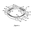
- FIG 2 is a perspective view of the illustrative IMU isolator 24 in Figure 1 .
- the illustrative IMU isolator 24 may include an inner ring 42 having an outer surface 47, and an outer ring 40 having an inner surface 49 situated adjacent the outer surface 47 of the inner ring 42.
- the IMU isolator 24 may also include an elastomer 44 provided between at least a portion of the inner ring 42 and at least a portion of the outer ring 40.
- the elastomer 44 may be a silicone rubber, however, it is contemplated that the elastomer 44 may be any material that may absorb energy and that may dampen vibration and shock during normal operation and during the impact between the inner ring 42 and outer ring 40.
- the illustrative inner ring 42 and outer ring 40 may be adapted to provide a rotation stop mechanism, such as interlocking portions, which may help prevent the inner ring 42 from excessively rotating relative to the outer ring 40. This may help protect the elastomer during high dynamic events. That is, the rotation stop mechanism may help prevent the inner ring 42 from "spinning out" of the outer ring 40 and tearing the elastomer 44 when exposed to high dynamic environments.
- a rotation stop mechanism such as interlocking portions
- the illustrative rotational stop mechanism may include a recessed portion 43 and a protruding portion 41.
- the inner ring 42 has an outer surface that may be designed to have at least one recessed portion 43.
- the outer ring 40 may be designed and machined to have an inner surface with at least one protruding portion 41 corresponding to the at least one recessed portion 43 of the inner ring 42.
- the inner ring 42 may have at least one protruding portion and the outer ring 40 may have at least one corresponding recessed portion.
- the protruding portion 41 may be positioned at least partially within the recessed portion 43 so that they are interlocking, which may inhibit or substantially inhibit excessive rotation of the inner ring 42 relative to the outer ring 40 when exposed to high rotational forces.
- high rotational forces may be provided by, for example, the "rifling" of a projectile that includes the IMU with the barrel of a gun or cannon.
- the use of four recessed portions 43 and protruding portions 41 is only illustrative and it is contemplated that any number of recessed portions 43 and protruding portions 41 may be used, as desired
- the illustrative IMU isolator 24 inner ring 42 may be adapted to mount the sensor suite thereto and the IMU isolator 24 outer ring 40 may be adapted to secure the cover member and base member thereto.
- the illustrative inner ring 42 may be adapted to mount the sensor suite thereto by provide one or more holes 48 to facilitate the insertion of fasteners. In the illustrative embodiment, there are three holes 48 provided for fasteners. However, it is contemplated that any number of holes 48 may be used depending on the design of the sensor suite.
- the outer ring 40 may provide one or more holes 46 for securing the base member and cover member thereto. In the illustrative embodiment, there are six holes 46 provided.
- any number of holes 46 may be provided to secure the base member and cover member to the outer ring 40, as desired.
- any method of fastening or securing the sensor suite to the inner ring 42 and any method of fastening or securing the cover member and base member to the outer ring 40 may be used, as desired.
- FIG 3 is a perspective assembly view of the illustrative IMU isolator 24 of Figure 2 .
- the illustrative IMU isolator 24 assembly includes the inner ring 42, the elastomer 44, and the outer ring 40.
- the inner ring 42 and outer ring 40 may be designed to provide a recessed portion 43 and a protruding portion 41. Once the inner ring 42 and the outer ring 40 are machined, or otherwise formed, the inner ring 42 may be positioned within the outer ring 40. Next the elastomer 44 may be provided between at least a portion of the inner ring 42 and at least a portion of the outer ring 40.
- the elastomer 44 may be provided in the outer ring 40 before positioning the inner ring 42 in the outer ring 40, the elastomer 44 may be provided around the inner ring 42 before positioning the inner ring 42 and elastomer 44 in the outer ring 40, or the elastomer 44 may be positioned in the outer ring 40 at the same or substantially the same time that the inner ring 42 is positioned in the outer ring 40.
- the inner ring 42 and outer ring 40 may be placed in a mold in which the elastomer 44 may be applied.
- the elastomer 44 may be applied between the entire inner ring 42 and the entire outer ring 40 or between a portion of the inner ring 42 and a portion of the outer ring 40, as desired.
- the elastomer 44 may be provided between the inner ring 42 and the outer ring 40 by spraying, coating, dipping, molding, or by any other suitable method as desired.
- the illustrative IMU isolator 24 may have a temperature range of -55 degrees Celsius to 90 degrees Celsius. Over this temperature range, the IMU isolator 24 may have a natural frequency of about 260 hertz (Hz). The natural frequency temperature variation may have a range of 50 Hz. In one case, the IMU isolator 24 may have a natural frequency of 225 Hz with an allowable range of 35 Hz over the temperature range.
- the illustrative IMU isolator 24 may also have a transmissibility that ranges from 3.0 to 7.0 over the temperature range. However, it is contemplated that any suitable temperature range, frequency, or transmissibility may be used, depending on the application.
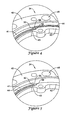
- FIG 4 is a perspective view of the illustrative rotational stop mechanism of the IMU isolator 24 of Figure 2 .
- the illustrative rotational stop mechanism includes the recessed portion 43 of the outer surface of the inner ring 42 and the protruding portion 41 of the inner surface of the outer ring 40.
- the recessed portion 43 and the protruding portion 41 may be situated so that the protruding portion 41 is at least partially within the recessed portion 43. With such an alignment, the side surface 52 of the recessed portion 43 of the inner ring 42 may come into contact with the side surface 50 of the protruding portion 41 of the outer ring 40 when the IMU isolator 24 experiences a significant rotational force.
- the illustrative rotation stop mechanism may cause the inner ring 42 and outer ring 40 to interlock, preventing or substantially preventing rotation of the inner ring 42 relative to the outer ring 40.
- the side surface 52 of the recessed portion 43 may recede at an angle of 90 degrees.
- the side surface 50 of the protruding portion 41 may be protruding at an angle similar to that of the recessed portion 43, in this case, 90 degrees. Additionally, in some cases, the side surface 52 of the recessed portion 43 may be recessed at an angle greater than 90 degrees.
- the side surface 50 of the protruding portion may also protrude at a corresponding angle. However, it is contemplated that the side surface 52 of the recessed portion 43 and the side surface 50 of the protruding portion 41 may have any suitable angle greater than or less than 90 degrees, as desired.
- the elastomer 44 may be positioned between a portion of the inner ring 42 and the outer ring 40, and in some cases, may be adjacent to the side surface 52 of the recessed portion 43 and the side surface 50 of the protruding portion 41, shown in region 54.
- the elastomer 44 may, for example, be provided in region 54 to help attenuate the shock and vibrational energy when the IMU isolator 24 bottoms out during a high rotational event. In this case, there is an elastomer-to-elastomer contact between the inner ring 42 and the outer ring 40.
- the elastomer 44 may be provided only on one surface causing an elastomer-to-metal contact or on no surface, as illustrated in Figure 6 , having a metal-to-metal contact.
- One advantage of providing elastomer 44 on at least one surface 50 or 52 may be the increased attenuation of shock and vibrational energy in the sensor suite of the IMU during a high rotational event.
- FIG 5 is a perspective view of another illustrative rotational stop mechanism of the IMU isolator 24 of Figure 2 . Similar to Figure 4 , the illustrative IMU isolator 24 has a rotational stop mechanism that includes the recessed portion 43 of the inner ring 42 and the protruding portion 41 of the outer ring 40. The recessed portion 43 and the protruding portion 41 may be positioned so that the protruding portion 41 is at least partially within the recessed portion 43.
- the side surface 52 of the recessed portion 43 of the inner ring 42 may come into contact with the side surface 50 of the protruding portion 41 of the outer ring 40, preventing or substantially preventing excessive rotation of the inner ring 42 relative to the outer ring 40 during a high rotational event.
- the elastomer 44 is not provided between the side surface 52 of the recessed portion 43 and the side surface 50 of the protruding portion 41, shown in region 55.
- Two reasons for not providing the elastomer 44 in region 55 may be the design constraints and the increased cost.
- the side surface 52 of the recessed portion 43 and the side surface 50 of the protruding portion 41 may come into contact as a metal-to-metal contact when the illustrative IMU isolator 24 is exposed to high rotation forces.
- a metal-to-metal contact may produce a reduced attenuation of shock and vibrational energy in the senor suite during such events, as compared to Figure 4 .
- elastomer 44 may be provided on both the side surface 50 and 52 of the recessed portion 43 and the protruding portion 41, on only the side surface 52 of the recessed portion 43, on only the side surface 50 of the protruding portion 41, or not provided at all between the side surfaces 50, 52 of the recessed portion 43 and protruding portion 41, as desired.
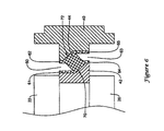
- FIG 6 is a schematic diagram of a cross-sectional view of the illustrative IMU isolator of Figure 2 .
- the illustrative IMU isolator includes inner ring 42, outer ring 40, and elastomer 44 extending therebetween.
- the illustrative elastomer 44 may be disposed over the entire height of the inner ring 42 and the entire height of the outer ring 40, if desired.
- the elastomer has a top gap 60 and a bottom gap 63. Under some circumstances, the IMU isolator may be exposed to translational forces causing a compression between the inner ring 42 and the outer ring 40.
- elastomer area 61 on the inner ring 42 may come into contact with elastomer area 62 on the outer ring 40.
- elastomer area 64 on the inner ring 42 may come into contact with elastomer area 65 on the outer ring 40.
- One advantage of having full surface coverage may be to help prevent a metal-to-metal or metal-to-elastomer contact.
- An elastomer-to-elastomer contact may have a higher attenuation of shock and vibrational energy, which may be advantageous when operating in high dynamic environments.
- the elastomer 44 may provide full surface coverage only on either the inner ring 42, such as areas 61 and 64, or only on the outer ring 40, such as areas 62 and 65 or on neither the inner or outer rings, as desired.
- the inner surface 72 of the outer ring 40 may be similarly shaped to the outer surface 70 of the inner ring 42 and not have any pointed regions.
- a non-pointed region is that when exposed to translational forces that cause a compression of the inner ring 42 and outer ring 40, a non-pointed region may spread out the force over the entire surface area of the inner ring 42 and the outer ring 40 and may not cause the elastomer 44 to tear or cut, whereas a pointed region may centralize the force in one point and cause the elastomer 44 to tear or cut, resulting in a metal-to-metal contact.
- the illustrative elastomer 44 may be symmetrical or nearly symmetrical in shape in the isolator.
- the symmetrical shape may provide an advantage of having the elastic center of the elastomer 44 at the geometric center of the isolator similarly located.
- the elastomer 44 may balance the axial and radial stiffness of the isolator at a ratio of approximately 1:1.
- the elastomer 44 may have a linear spring rate over an expected deflection range associated with shock and vibrational energy during a high dynamic event. In one case, the expected deflection range may be approximately 0.0076 cm (0.003 inches). However, it is contemplated that the elastomer 44 may have a linear spring rate or stiffness up to a deflection of approximately 0.0356 cm (0.014 inches) in the radial direction and an even greater deflection range in the axial direction.
- the illustrative isolator may provide protection and/or attenuation of the inertial sensors in all six degrees of freedom, such as the longitudinal, lateral, axial, roll, pitch, and yaw degrees of freedom.
- the illustrative elastomer 44 may provide the protection and/or attenuation of the inertial sensor in three degrees of freedom, such as, for example, the longitudinal, lateral, and the axial degrees of freedom.
Claims (5)
- Isolator für eine Trägheitsmesseinheit (IMU), der Folgendes umfasst:einen starren äußeren Ring (40) zur Befestigung an einem Stützelement der IMU, wobei der äußere Ring eine innere Oberfläche (72) mit mindestens einem vorspringenden Abschnitt (41) aufweist;einen starren inneren Ring (42) zur Befestigung an einer Sensorenreihe der IMU, wobei der innere Ring eine an die innere Oberfläche (72) des äußeren Rings (40) angrenzende äußere Oberfläche (70) aufweist, wobei die äußere Oberfläche (70) des inneren Rings (42) mindestens einen rückspringenden Abschnitt (43) aufweist; undein Elastomer (44), das zwischen mindestens einem Abschnitt des äußeren Rings (40) und mindestens einem Abschnitt des inneren Rings (42) positioniert ist,wobei der vorspringende Abschnitt (41) mindestens teilweise innerhalb des rückspringenden Abschnitts (43) positioniert ist; und
wobei der vorspringende Abschnitt (41) mindestens eine Seitenoberfläche (50) und der rückspringende Abschnitt (43) mindestens eine Seitenoberfläche (52) aufweist,
wobei die Seitenoberflächen (50, 52) verriegelbar sind, um eine Drehung des inneren Rings (42) im Verhältnis zum äußeren Ring (40) zu begrenzen. - Isolator nach Anspruch 1, bei dem das Elastomer (44) zwischen der mindestens einen Seitenoberfläche (52) des rückspringenden Abschnitts (43) und der mindestens einen Seitenoberfläche (50) des vorspringenden Abschnitts (41) positioniert ist.
- Isolator nach Anspruch 1, bei dem das Elastomer (44) nicht zwischen der mindestens einen Seitenoberfläche (52) des rückspringenden Abschnitts (43) und der mindestens einen Seitenoberfläche (50) des vorspringenden Abschnitts (41) positioniert ist.
- Isolator nach einem der vorstehend aufgeführten Ansprüche, bei dem die Sensorenreihe mindestens einen Trägheitssensor aufweist.
- Isolator nach Anspruch 4, der weiterhin ein Abdeckelement (14) und ein Basiselement (34), die am äußeren Ring (40) befestigt sind, umfasst, so dass dadurch ein Hohlraum für die Sensorenreihe entsteht,
wobei der Hohlraum durch Hohlraumwände definiert ist.
Applications Claiming Priority (1)
| Application Number | Priority Date | Filing Date | Title |
|---|---|---|---|
| US11/164,355 US20070113702A1 (en) | 2005-11-18 | 2005-11-18 | Isolation system for an inertial measurement unit |
Publications (3)
| Publication Number | Publication Date |
|---|---|
| EP1788277A2 EP1788277A2 (de) | 2007-05-23 |
| EP1788277A3 EP1788277A3 (de) | 2007-08-08 |
| EP1788277B1 true EP1788277B1 (de) | 2009-11-18 |
Family
ID=37887794
Family Applications (1)
| Application Number | Title | Priority Date | Filing Date |
|---|---|---|---|
| EP06124381A Expired - Fee Related EP1788277B1 (de) | 2005-11-18 | 2006-11-20 | Isolierungssystem für Trägheitsmesseinheit |
Country Status (4)
| Country | Link |
|---|---|
| US (1) | US20070113702A1 (de) |
| EP (1) | EP1788277B1 (de) |
| JP (1) | JP2007163471A (de) |
| DE (1) | DE602006010502D1 (de) |
Families Citing this family (28)
| Publication number | Priority date | Publication date | Assignee | Title |
|---|---|---|---|---|
| US7404324B2 (en) * | 2005-08-19 | 2008-07-29 | Honeywell International Inc. | Gunhard shock isolation system |
| US8266960B2 (en) | 2009-04-10 | 2012-09-18 | Honeywell International Inc. | Systems and methods for potted shock isolation |
| US8573056B1 (en) * | 2010-06-04 | 2013-11-05 | The United States Of America As Represented By The Secretary Of The Army | Guided projectile with motion restricting piezoelectric actuator |
| CN102121829B (zh) | 2010-08-09 | 2013-06-12 | 汪滔 | 一种微型惯性测量系统 |
| US10292445B2 (en) | 2011-02-24 | 2019-05-21 | Rochester Institute Of Technology | Event monitoring dosimetry apparatuses and methods thereof |
| US9339224B2 (en) | 2011-02-24 | 2016-05-17 | Rochester Institute Of Technology | Event dosimeter devices and methods thereof |
| CN102980584B (zh) | 2011-09-02 | 2017-12-19 | 深圳市大疆创新科技有限公司 | 一种无人飞行器惯性测量模块 |
| US8931765B2 (en) * | 2012-09-27 | 2015-01-13 | Honeywell International Inc. | Systems and methods for high frequency isolation |
| DE102013014622A1 (de) * | 2013-09-02 | 2015-03-05 | Northrop Grumman Litef Gmbh | System und Verfahren zum Bestimmen von Bewegungen und Schwingungen bewegter Strukturen |
| WO2015161517A1 (en) | 2014-04-25 | 2015-10-29 | SZ DJI Technology Co., Ltd. | Inertial sensing device |
| US20160054355A1 (en) * | 2014-08-20 | 2016-02-25 | Honeywell International Inc. | Compact inertial measurement unit with interface adapter |
| US9541568B2 (en) * | 2014-10-08 | 2017-01-10 | Honeywell International Inc. | Systems and methods for isolated sensor device protection |
| GB2536037A (en) * | 2015-03-05 | 2016-09-07 | Atlantic Inertial Systems Ltd | Anti-vibration mounting system |
| CN113959440A (zh) | 2015-04-07 | 2022-01-21 | 深圳市大疆创新科技有限公司 | 用于提供简单而可靠的惯性测量单元的系统和方法 |
| CN104833821B (zh) * | 2015-05-07 | 2017-11-03 | 深圳导远科技有限公司 | 环形悬挂式内隔振的惯性测量组件 |
| US9625284B2 (en) * | 2015-09-04 | 2017-04-18 | Honeywell International Inc | Shock mount in environment sensor protector for non-isolated systems |
| KR101724332B1 (ko) * | 2015-12-16 | 2017-04-07 | 국방과학연구소 | 관성 측정 장치 |
| US20170350913A1 (en) * | 2016-06-03 | 2017-12-07 | Green Power Monitoring Systems, Inc. | Suspension System |
| CN108050191B (zh) * | 2017-12-13 | 2020-07-03 | 中国飞机强度研究所 | 一种圆环形金属橡胶隔振器 |
| WO2019156585A1 (en) * | 2018-02-08 | 2019-08-15 | Llc "Topcon Positioning Systems" | Wedged three-axis inertial sensor damper-suspension |
| GB2575978A (en) * | 2018-07-30 | 2020-02-05 | Innalabs Ltd | Gyroscope |
| US11312619B1 (en) | 2018-10-04 | 2022-04-26 | EngeniusMicro, LLC | Methods of manufacture of microisolators and devices for mechanical isolation or mechanical damping of microfabricated inertial sensors |
| CN111197981A (zh) * | 2018-11-16 | 2020-05-26 | 北京自动化控制设备研究所 | 一种对惯性组合整体屏蔽的双轴旋转装置 |
| JP6545918B1 (ja) * | 2019-05-22 | 2019-07-17 | Imv株式会社 | 加速度センサコアユニット、加速度センサを載置する基板のたわみを防止する方法 |
| CN110425250A (zh) * | 2019-07-17 | 2019-11-08 | 北京自动化控制设备研究所 | 用于mems惯性仪表系统的一体化减振结构 |
| US11459231B2 (en) | 2020-11-23 | 2022-10-04 | United States Government As Represented By The Secretary Of The Army | Microelectronic isolation system |
| CN113090709B (zh) * | 2021-04-12 | 2024-04-09 | 西安航弓机电科技有限公司 | 一种带有隔振结构的惯性模块 |
| KR20240011997A (ko) | 2022-07-20 | 2024-01-29 | 국방과학연구소 | 관성센서 조립체 및 관성센서 조립체용 관성센서 블록 단위체 |
Family Cites Families (53)
| Publication number | Priority date | Publication date | Assignee | Title |
|---|---|---|---|---|
| FR663418A (fr) * | 1928-02-17 | 1929-08-21 | Jules Richard Sa Des Ets | Dispositif de fixation élastique d'appareils de précision |
| US3167294A (en) * | 1961-01-09 | 1965-01-26 | Zenas B Andrews | Missile launcher shock absorber |
| US3483623A (en) * | 1968-08-20 | 1969-12-16 | George R Kruzell | Shock-proof telescopic gun sight mount |
| FR2058451A5 (de) * | 1969-09-05 | 1971-05-28 | Aquitaine Petrole | |
| US3843108A (en) * | 1973-01-31 | 1974-10-22 | Singer Co | Vibration and shock isolated gyroscope assembly |
| US3933012A (en) * | 1973-07-13 | 1976-01-20 | Trw Inc. | Torque absorber for submergible pumps |
| US4026054A (en) * | 1976-02-02 | 1977-05-31 | Snyder Wesley L | Laser aiming system for weapons |
| US4178811A (en) * | 1977-06-15 | 1979-12-18 | Wallace Murray Corporation | Meta reinforced plastic damper hub |
| US4114246A (en) * | 1977-06-29 | 1978-09-19 | Houdaille Industries, Inc. | Method of and means for making tuned viscous torsional vibration dampers |
| US4228664A (en) * | 1978-11-08 | 1980-10-21 | Douville-Johnston Corporation | Flexible drive coupling |
| GB2068503B (en) * | 1980-01-25 | 1983-07-06 | Concentric Pumps Ltd | Vibration dampers |
| US4494072A (en) * | 1980-04-21 | 1985-01-15 | Exploration Logging, Inc. | Well logging apparatus with replaceable sensor carrying insulating sleeve disposed in rotation restrained position around a drill string |
| JPS5812747U (ja) * | 1981-07-20 | 1983-01-26 | 小松ゼノア株式会社 | 防振装置 |
| US4524675A (en) * | 1982-08-03 | 1985-06-25 | The United States Of America As Represented By The Secretary Of The Army | Detachably connectable sight assembly for a small defense weapon |
| DE3403858A1 (de) * | 1984-02-03 | 1985-08-14 | Metzeler Kautschuk GmbH, 8000 München | An einer welle befestigbarer tragring aus kunststoff fuer einen drehschwingungsdaempfer |
| SE459993B (sv) * | 1985-01-25 | 1989-08-28 | Philips Norden Ab | Anordning foer eldledning vid en kanon innefattande en foeljeradarenhet med radarsaendare/mottagare och antennorgan |
| US4581933A (en) * | 1985-02-04 | 1986-04-15 | Penn Airborne Products Company | Aircraft casing indicator seal |
| DE3514268A1 (de) * | 1985-04-19 | 1986-10-23 | Metzeler Kautschuk GmbH, 8000 München | Vorspannbares und hydraulisches gedaempftes lagerelement |
| US5425287A (en) * | 1986-08-29 | 1995-06-20 | Beattie; James C. | System for damping vibration of crankshafts and the like |
| US5299468A (en) * | 1989-08-04 | 1994-04-05 | Withers Graham R | Elastomeric vibrational dampers |
| US4936190A (en) * | 1989-09-20 | 1990-06-26 | The United States Of America As Represented By The Secretary Of The Army | Electrooptical muzzle sight |
| US4972619A (en) * | 1989-11-29 | 1990-11-27 | Eckert Kenneth I | Rifle sighting apparatus |
| US5040764A (en) * | 1990-09-28 | 1991-08-20 | The United States Of America As Represented By The Secretary Of The Navy | Low frequency vibration absorber |
| US5237871A (en) * | 1990-10-12 | 1993-08-24 | Teledyne Industries Incorporated | Vibration attenuation assembly with venting passageway |
| US5305981A (en) * | 1991-10-31 | 1994-04-26 | Honeywell Inc. | Multiaxis vibration isolation system |
| US5267720A (en) * | 1991-12-06 | 1993-12-07 | Sperry Marine Inc. | Structureborne noise isolator |
| US5231893A (en) * | 1991-12-10 | 1993-08-03 | Simpson Industries, Inc. | Dual mode damper |
| US5189245A (en) * | 1992-01-02 | 1993-02-23 | The United States Of America As Represented By The Secretary Of The Army | Thermally and mechanically stable muzzle reference system collimator assembly |
| US5368271A (en) * | 1992-03-02 | 1994-11-29 | Hughes Aircraft Company | Gimbal vibration isolation system |
| DE4209610C1 (de) * | 1992-03-25 | 1993-03-11 | Fa. Carl Freudenberg, 6940 Weinheim, De | |
| DE4238512C1 (de) * | 1992-11-14 | 1994-01-20 | Deutsche Aerospace | Inertialstabilisierungssystem |
| US5363700A (en) * | 1992-11-17 | 1994-11-15 | Honeywell Inc. | Skewed axis inertial sensor assembly |
| US5360236A (en) * | 1992-12-14 | 1994-11-01 | Honeywell Inc. | Apparatus and methods for mounting an inertial sensor chassis to an aircraft support frame |
| US5474499A (en) * | 1993-07-12 | 1995-12-12 | The United States Of America As Represented By The Secretary Of The Navy | Flexible drive shaft coupling |
| US5389746A (en) * | 1994-06-30 | 1995-02-14 | The United States Of America As Represented By The Secretary Of The Navy | Submarine hull structures providing acoustically isolated hull openings |
| US5529277A (en) * | 1994-09-20 | 1996-06-25 | Ball Corporation | Suspension system having two degrees of rotational freedom |
| JPH09303354A (ja) * | 1996-05-21 | 1997-11-25 | Kioritz Corp | 抜け止め構造体、及び、該抜け止め構造体を備えた刈払機 |
| US5803213A (en) * | 1997-02-03 | 1998-09-08 | Honeywell Inc. | Heavy load vibration isolation apparatus |
| US5947240A (en) * | 1997-02-03 | 1999-09-07 | Honeywell, Inc. | Load vibration isolation apparatus |
| US5878980A (en) * | 1997-02-05 | 1999-03-09 | Hughes Electronics Corporation | Attenuation ring |
| US5890569A (en) * | 1997-06-06 | 1999-04-06 | Honeywell Inc. | Vibration isolation system for an inertial sensor assembly |
| US6113030A (en) * | 1997-11-17 | 2000-09-05 | Lord Corporation | Readily changeable isolator and method of assembly thereof |
| US6237463B1 (en) * | 1999-06-14 | 2001-05-29 | Honeywell Inc. | Isolation system mount for mounting sensitive electronic equipment to non-recoiled artillery |
| US6202961B1 (en) * | 2000-03-21 | 2001-03-20 | Csa Engineering | Passive, multi-axis, highly damped, shock isolation mounts for spacecraft |
| US6808455B1 (en) * | 2000-05-03 | 2004-10-26 | Michael Solorenko | Torsional shock absorber for a drill string |
| US6522992B1 (en) * | 2000-05-24 | 2003-02-18 | American Gnc Corporation | Core inertial measurement unit |
| US6578682B2 (en) * | 2001-04-26 | 2003-06-17 | Honeywell International Inc. | Compact vibration isolation system for an inertial sensor assembly |
| US6993989B2 (en) * | 2002-04-26 | 2006-02-07 | Denso Corporation | Starting apparatus |
| US6959682B2 (en) * | 2002-09-05 | 2005-11-01 | General Motors Corporation | Engine balancer with chain drive vibration isolation |
| US20040150144A1 (en) * | 2003-01-30 | 2004-08-05 | Honeywell International Inc. | Elastomeric vibration and shock isolation for inertial sensor assemblies |
| US6704619B1 (en) * | 2003-05-24 | 2004-03-09 | American Gnc Corporation | Method and system for universal guidance and control of automated machines |
| US6879875B1 (en) * | 2003-09-20 | 2005-04-12 | American Gnc Corporation | Low cost multisensor high precision positioning and data integrated method and system thereof |
| US7448306B2 (en) * | 2004-12-21 | 2008-11-11 | Honeywell International Inc. | Pointing device inertial isolation and alignment mounting system |
-
2005
- 2005-11-18 US US11/164,355 patent/US20070113702A1/en not_active Abandoned
-
2006
- 2006-11-20 JP JP2006313193A patent/JP2007163471A/ja not_active Withdrawn
- 2006-11-20 DE DE602006010502T patent/DE602006010502D1/de active Active
- 2006-11-20 EP EP06124381A patent/EP1788277B1/de not_active Expired - Fee Related
Also Published As
| Publication number | Publication date |
|---|---|
| JP2007163471A (ja) | 2007-06-28 |
| DE602006010502D1 (de) | 2009-12-31 |
| EP1788277A2 (de) | 2007-05-23 |
| EP1788277A3 (de) | 2007-08-08 |
| US20070113702A1 (en) | 2007-05-24 |
Similar Documents
| Publication | Publication Date | Title |
|---|---|---|
| EP1788277B1 (de) | Isolierungssystem für Trägheitsmesseinheit | |
| US7404324B2 (en) | Gunhard shock isolation system | |
| AU2004252398B2 (en) | Elastomeric vibration and shock isolation for inertial sensor assemblies | |
| CA2445015C (en) | Compact vibration isolation system for an inertial sensor assembly | |
| RU2219498C2 (ru) | Виброизолирующая система для блока инерциальных датчиков | |
| US20100257932A1 (en) | Systems and methods for potted shock isolation | |
| US20100037694A1 (en) | Snubbing system for a suspended body | |
| CN111397601B (zh) | 一种微惯性测量单元抗冲击减振结构及减振系统 | |
| EP2712841B1 (de) | System und Verfahren zur Isolierung von MEMS gegen hohe Frequenzen | |
| WO2006073632A9 (en) | Gas supported inertial sensor system | |
| US20190178904A1 (en) | Device, system and method for stress-sensitive component isolation in severe environments | |
| US9625284B2 (en) | Shock mount in environment sensor protector for non-isolated systems | |
| CN108036781A (zh) | 频带自适应抗振陀螺仪 | |
| EP3009846B1 (de) | Isolierte sensorvorrichtung mit isolator und aufprall-interface | |
| EP0675825B1 (de) | Vorrichtung zur nutationsdämpfung für kreisel | |
| CN107628261B (zh) | 一种imu气压计组件及无人机 | |
| CN108146645A (zh) | 一种imu机构及无人机 | |
| KR101724332B1 (ko) | 관성 측정 장치 | |
| Veprik et al. | Synthesis of snubber's spectral characteristics for vibration protection of sensitive components in airborne gyrostabilized electro-optic payloads |
Legal Events
| Date | Code | Title | Description |
|---|---|---|---|
| PUAI | Public reference made under article 153(3) epc to a published international application that has entered the european phase |
Free format text: ORIGINAL CODE: 0009012 |
|
| AK | Designated contracting states |
Kind code of ref document: A2 Designated state(s): AT BE BG CH CY CZ DE DK EE ES FI FR GB GR HU IE IS IT LI LT LU LV MC NL PL PT RO SE SI SK TR |
|
| AX | Request for extension of the european patent |
Extension state: AL BA HR MK YU |
|
| PUAL | Search report despatched |
Free format text: ORIGINAL CODE: 0009013 |
|
| AK | Designated contracting states |
Kind code of ref document: A3 Designated state(s): AT BE BG CH CY CZ DE DK EE ES FI FR GB GR HU IE IS IT LI LT LU LV MC NL PL PT RO SE SI SK TR |
|
| AX | Request for extension of the european patent |
Extension state: AL BA HR MK YU |
|
| 17P | Request for examination filed |
Effective date: 20080208 |
|
| 17Q | First examination report despatched |
Effective date: 20080311 |
|
| AKX | Designation fees paid |
Designated state(s): DE FR GB |
|
| GRAP | Despatch of communication of intention to grant a patent |
Free format text: ORIGINAL CODE: EPIDOSNIGR1 |
|
| GRAS | Grant fee paid |
Free format text: ORIGINAL CODE: EPIDOSNIGR3 |
|
| GRAA | (expected) grant |
Free format text: ORIGINAL CODE: 0009210 |
|
| AK | Designated contracting states |
Kind code of ref document: B1 Designated state(s): DE FR GB |
|
| REG | Reference to a national code |
Ref country code: GB Ref legal event code: FG4D |
|
| REF | Corresponds to: |
Ref document number: 602006010502 Country of ref document: DE Date of ref document: 20091231 Kind code of ref document: P |
|
| PGFP | Annual fee paid to national office [announced via postgrant information from national office to epo] |
Ref country code: DE Payment date: 20091130 Year of fee payment: 4 |
|
| PGFP | Annual fee paid to national office [announced via postgrant information from national office to epo] |
Ref country code: FR Payment date: 20091203 Year of fee payment: 4 |
|
| PLBE | No opposition filed within time limit |
Free format text: ORIGINAL CODE: 0009261 |
|
| STAA | Information on the status of an ep patent application or granted ep patent |
Free format text: STATUS: NO OPPOSITION FILED WITHIN TIME LIMIT |
|
| 26N | No opposition filed |
Effective date: 20100819 |
|
| GBPC | Gb: european patent ceased through non-payment of renewal fee |
Effective date: 20101120 |
|
| REG | Reference to a national code |
Ref country code: FR Ref legal event code: ST Effective date: 20110801 |
|
| REG | Reference to a national code |
Ref country code: DE Ref legal event code: R119 Ref document number: 602006010502 Country of ref document: DE Effective date: 20110601 Ref country code: DE Ref legal event code: R119 Ref document number: 602006010502 Country of ref document: DE Effective date: 20110531 |
|
| PG25 | Lapsed in a contracting state [announced via postgrant information from national office to epo] |
Ref country code: FR Free format text: LAPSE BECAUSE OF NON-PAYMENT OF DUE FEES Effective date: 20101130 |
|
| PG25 | Lapsed in a contracting state [announced via postgrant information from national office to epo] |
Ref country code: GB Free format text: LAPSE BECAUSE OF NON-PAYMENT OF DUE FEES Effective date: 20101120 |
|
| PG25 | Lapsed in a contracting state [announced via postgrant information from national office to epo] |
Ref country code: DE Free format text: LAPSE BECAUSE OF NON-PAYMENT OF DUE FEES Effective date: 20110531 |
|
| P01 | Opt-out of the competence of the unified patent court (upc) registered |
Effective date: 20230525 |