EP1788111A2 - Resin product, production method for the same, and deposition method for a metallic coating - Google Patents
Resin product, production method for the same, and deposition method for a metallic coating Download PDFInfo
- Publication number
- EP1788111A2 EP1788111A2 EP20060122842 EP06122842A EP1788111A2 EP 1788111 A2 EP1788111 A2 EP 1788111A2 EP 20060122842 EP20060122842 EP 20060122842 EP 06122842 A EP06122842 A EP 06122842A EP 1788111 A2 EP1788111 A2 EP 1788111A2
- Authority
- EP
- European Patent Office
- Prior art keywords
- coating
- inorganic
- undercoating
- metallic
- resin product
- Prior art date
- Legal status (The legal status is an assumption and is not a legal conclusion. Google has not performed a legal analysis and makes no representation as to the accuracy of the status listed.)
- Withdrawn
Links
- 238000000576 coating method Methods 0.000 title claims abstract description 182
- 239000011248 coating agent Substances 0.000 title claims abstract description 179
- 239000011347 resin Substances 0.000 title claims abstract description 52
- 229920005989 resin Polymers 0.000 title claims abstract description 52
- 238000000151 deposition Methods 0.000 title claims description 21
- 238000004519 manufacturing process Methods 0.000 title claims description 11
- 238000000034 method Methods 0.000 claims abstract description 36
- 238000005240 physical vapour deposition Methods 0.000 claims abstract description 22
- 239000000463 material Substances 0.000 claims description 91
- GWEVSGVZZGPLCZ-UHFFFAOYSA-N Titan oxide Chemical compound O=[Ti]=O GWEVSGVZZGPLCZ-UHFFFAOYSA-N 0.000 claims description 20
- 239000010408 film Substances 0.000 claims description 20
- 239000011651 chromium Substances 0.000 claims description 18
- XUIMIQQOPSSXEZ-UHFFFAOYSA-N Silicon Chemical compound [Si] XUIMIQQOPSSXEZ-UHFFFAOYSA-N 0.000 claims description 11
- 229910052710 silicon Inorganic materials 0.000 claims description 11
- 239000010703 silicon Substances 0.000 claims description 11
- 229910010272 inorganic material Inorganic materials 0.000 claims description 9
- 239000010409 thin film Substances 0.000 claims description 9
- 229910052738 indium Inorganic materials 0.000 claims description 8
- 150000002484 inorganic compounds Chemical class 0.000 claims description 8
- 229910000765 intermetallic Inorganic materials 0.000 claims description 8
- 229910052804 chromium Inorganic materials 0.000 claims description 7
- OGIDPMRJRNCKJF-UHFFFAOYSA-N titanium oxide Inorganic materials [Ti]=O OGIDPMRJRNCKJF-UHFFFAOYSA-N 0.000 claims description 5
- VYZAMTAEIAYCRO-UHFFFAOYSA-N Chromium Chemical compound [Cr] VYZAMTAEIAYCRO-UHFFFAOYSA-N 0.000 claims description 4
- APFVFJFRJDLVQX-UHFFFAOYSA-N indium atom Chemical compound [In] APFVFJFRJDLVQX-UHFFFAOYSA-N 0.000 claims description 4
- 150000003377 silicon compounds Chemical class 0.000 claims description 4
- 150000003609 titanium compounds Chemical class 0.000 claims description 4
- 239000002585 base Substances 0.000 description 46
- VYPSYNLAJGMNEJ-UHFFFAOYSA-N Silicium dioxide Chemical compound O=[Si]=O VYPSYNLAJGMNEJ-UHFFFAOYSA-N 0.000 description 25
- 238000007740 vapor deposition Methods 0.000 description 21
- 230000000052 comparative effect Effects 0.000 description 17
- 238000002834 transmittance Methods 0.000 description 16
- NIXOWILDQLNWCW-UHFFFAOYSA-N acrylic acid group Chemical group C(C=C)(=O)O NIXOWILDQLNWCW-UHFFFAOYSA-N 0.000 description 14
- 229910052681 coesite Inorganic materials 0.000 description 12
- 229910052906 cristobalite Inorganic materials 0.000 description 12
- 239000002923 metal particle Substances 0.000 description 12
- 239000000377 silicon dioxide Substances 0.000 description 12
- 229910052682 stishovite Inorganic materials 0.000 description 12
- 229910052905 tridymite Inorganic materials 0.000 description 12
- 239000004417 polycarbonate Substances 0.000 description 10
- 230000008901 benefit Effects 0.000 description 6
- 239000010410 layer Substances 0.000 description 5
- 238000004544 sputter deposition Methods 0.000 description 5
- 229910052581 Si3N4 Inorganic materials 0.000 description 4
- 230000015572 biosynthetic process Effects 0.000 description 4
- 150000001875 compounds Chemical class 0.000 description 4
- 238000005260 corrosion Methods 0.000 description 4
- 230000007797 corrosion Effects 0.000 description 4
- 230000008021 deposition Effects 0.000 description 4
- 238000001035 drying Methods 0.000 description 4
- 230000000694 effects Effects 0.000 description 4
- 238000002474 experimental method Methods 0.000 description 4
- 230000007246 mechanism Effects 0.000 description 4
- 230000001681 protective effect Effects 0.000 description 4
- 229920000178 Acrylic resin Polymers 0.000 description 3
- 239000004925 Acrylic resin Substances 0.000 description 3
- 239000011521 glass Substances 0.000 description 3
- 238000000465 moulding Methods 0.000 description 3
- 229910052760 oxygen Inorganic materials 0.000 description 3
- 229920000515 polycarbonate Polymers 0.000 description 3
- LIVNPJMFVYWSIS-UHFFFAOYSA-N silicon monoxide Chemical compound [Si-]#[O+] LIVNPJMFVYWSIS-UHFFFAOYSA-N 0.000 description 3
- 238000005507 spraying Methods 0.000 description 3
- IJGRMHOSHXDMSA-UHFFFAOYSA-N Atomic nitrogen Chemical compound N#N IJGRMHOSHXDMSA-UHFFFAOYSA-N 0.000 description 2
- UQSXHKLRYXJYBZ-UHFFFAOYSA-N Iron oxide Chemical compound [Fe]=O UQSXHKLRYXJYBZ-UHFFFAOYSA-N 0.000 description 2
- QVGXLLKOCUKJST-UHFFFAOYSA-N atomic oxygen Chemical compound [O] QVGXLLKOCUKJST-UHFFFAOYSA-N 0.000 description 2
- CETPSERCERDGAM-UHFFFAOYSA-N ceric oxide Chemical compound O=[Ce]=O CETPSERCERDGAM-UHFFFAOYSA-N 0.000 description 2
- 239000011247 coating layer Substances 0.000 description 2
- 230000003247 decreasing effect Effects 0.000 description 2
- 238000013461 design Methods 0.000 description 2
- 238000010438 heat treatment Methods 0.000 description 2
- 230000002401 inhibitory effect Effects 0.000 description 2
- 238000007737 ion beam deposition Methods 0.000 description 2
- 238000007733 ion plating Methods 0.000 description 2
- 238000001659 ion-beam spectroscopy Methods 0.000 description 2
- 229910052751 metal Inorganic materials 0.000 description 2
- 239000002184 metal Substances 0.000 description 2
- 239000001301 oxygen Substances 0.000 description 2
- 229920000728 polyester Polymers 0.000 description 2
- 229920000915 polyvinyl chloride Polymers 0.000 description 2
- 238000012805 post-processing Methods 0.000 description 2
- 229910052984 zinc sulfide Inorganic materials 0.000 description 2
- JOYRKODLDBILNP-UHFFFAOYSA-N Ethyl urethane Chemical compound CCOC(N)=O JOYRKODLDBILNP-UHFFFAOYSA-N 0.000 description 1
- 229910001111 Fine metal Inorganic materials 0.000 description 1
- AFCARXCZXQIEQB-UHFFFAOYSA-N N-[3-oxo-3-(2,4,6,7-tetrahydrotriazolo[4,5-c]pyridin-5-yl)propyl]-2-[[3-(trifluoromethoxy)phenyl]methylamino]pyrimidine-5-carboxamide Chemical compound O=C(CCNC(=O)C=1C=NC(=NC=1)NCC1=CC(=CC=C1)OC(F)(F)F)N1CC2=C(CC1)NN=N2 AFCARXCZXQIEQB-UHFFFAOYSA-N 0.000 description 1
- GEIAQOFPUVMAGM-UHFFFAOYSA-N Oxozirconium Chemical compound [Zr]=O GEIAQOFPUVMAGM-UHFFFAOYSA-N 0.000 description 1
- 239000004793 Polystyrene Substances 0.000 description 1
- 229910018557 Si O Inorganic materials 0.000 description 1
- 229910009815 Ti3O5 Inorganic materials 0.000 description 1
- 229910003077 Ti−O Inorganic materials 0.000 description 1
- 206010047289 Ventricular extrasystoles Diseases 0.000 description 1
- 239000005083 Zinc sulfide Substances 0.000 description 1
- 239000002253 acid Substances 0.000 description 1
- 230000009471 action Effects 0.000 description 1
- 239000003513 alkali Substances 0.000 description 1
- AZDRQVAHHNSJOQ-UHFFFAOYSA-N alumane Chemical class [AlH3] AZDRQVAHHNSJOQ-UHFFFAOYSA-N 0.000 description 1
- PNEYBMLMFCGWSK-UHFFFAOYSA-N aluminium oxide Inorganic materials [O-2].[O-2].[O-2].[Al+3].[Al+3] PNEYBMLMFCGWSK-UHFFFAOYSA-N 0.000 description 1
- 230000015556 catabolic process Effects 0.000 description 1
- 229940044927 ceric oxide Drugs 0.000 description 1
- 150000001785 cerium compounds Chemical class 0.000 description 1
- 229910000422 cerium(IV) oxide Inorganic materials 0.000 description 1
- 230000008859 change Effects 0.000 description 1
- 238000007796 conventional method Methods 0.000 description 1
- 229910052593 corundum Inorganic materials 0.000 description 1
- 239000013078 crystal Substances 0.000 description 1
- 238000006731 degradation reaction Methods 0.000 description 1
- 238000009792 diffusion process Methods 0.000 description 1
- 238000010894 electron beam technology Methods 0.000 description 1
- 238000005530 etching Methods 0.000 description 1
- 230000006872 improvement Effects 0.000 description 1
- 238000002347 injection Methods 0.000 description 1
- 239000007924 injection Substances 0.000 description 1
- 150000007529 inorganic bases Chemical class 0.000 description 1
- 239000011147 inorganic material Substances 0.000 description 1
- 150000002506 iron compounds Chemical class 0.000 description 1
- JEIPFZHSYJVQDO-UHFFFAOYSA-N iron(III) oxide Inorganic materials O=[Fe]O[Fe]=O JEIPFZHSYJVQDO-UHFFFAOYSA-N 0.000 description 1
- 238000002156 mixing Methods 0.000 description 1
- 239000000203 mixture Substances 0.000 description 1
- 238000012986 modification Methods 0.000 description 1
- 230000004048 modification Effects 0.000 description 1
- 229910052757 nitrogen Inorganic materials 0.000 description 1
- 150000007530 organic bases Chemical class 0.000 description 1
- 150000002894 organic compounds Chemical class 0.000 description 1
- 239000011368 organic material Substances 0.000 description 1
- 230000008520 organization Effects 0.000 description 1
- TWNQGVIAIRXVLR-UHFFFAOYSA-N oxo(oxoalumanyloxy)alumane Chemical compound O=[Al]O[Al]=O TWNQGVIAIRXVLR-UHFFFAOYSA-N 0.000 description 1
- 239000002245 particle Substances 0.000 description 1
- 229920002223 polystyrene Polymers 0.000 description 1
- 229920002635 polyurethane Polymers 0.000 description 1
- 239000004814 polyurethane Substances 0.000 description 1
- HQVNEWCFYHHQES-UHFFFAOYSA-N silicon nitride Chemical compound N12[Si]34N5[Si]62N3[Si]51N64 HQVNEWCFYHHQES-UHFFFAOYSA-N 0.000 description 1
- 229910052814 silicon oxide Inorganic materials 0.000 description 1
- 239000000126 substance Substances 0.000 description 1
- 229920005992 thermoplastic resin Polymers 0.000 description 1
- 229910052718 tin Inorganic materials 0.000 description 1
- -1 titanium oxide (TiO Chemical class 0.000 description 1
- 238000013519 translation Methods 0.000 description 1
- 229910001845 yogo sapphire Inorganic materials 0.000 description 1
- 150000003752 zinc compounds Chemical class 0.000 description 1
- DRDVZXDWVBGGMH-UHFFFAOYSA-N zinc;sulfide Chemical compound [S-2].[Zn+2] DRDVZXDWVBGGMH-UHFFFAOYSA-N 0.000 description 1
- 150000003755 zirconium compounds Chemical class 0.000 description 1
Images


Classifications
-
- C—CHEMISTRY; METALLURGY
- C23—COATING METALLIC MATERIAL; COATING MATERIAL WITH METALLIC MATERIAL; CHEMICAL SURFACE TREATMENT; DIFFUSION TREATMENT OF METALLIC MATERIAL; COATING BY VACUUM EVAPORATION, BY SPUTTERING, BY ION IMPLANTATION OR BY CHEMICAL VAPOUR DEPOSITION, IN GENERAL; INHIBITING CORROSION OF METALLIC MATERIAL OR INCRUSTATION IN GENERAL
- C23C—COATING METALLIC MATERIAL; COATING MATERIAL WITH METALLIC MATERIAL; SURFACE TREATMENT OF METALLIC MATERIAL BY DIFFUSION INTO THE SURFACE, BY CHEMICAL CONVERSION OR SUBSTITUTION; COATING BY VACUUM EVAPORATION, BY SPUTTERING, BY ION IMPLANTATION OR BY CHEMICAL VAPOUR DEPOSITION, IN GENERAL
- C23C14/00—Coating by vacuum evaporation, by sputtering or by ion implantation of the coating forming material
- C23C14/06—Coating by vacuum evaporation, by sputtering or by ion implantation of the coating forming material characterised by the coating material
- C23C14/14—Metallic material, boron or silicon
- C23C14/20—Metallic material, boron or silicon on organic substrates
-
- C—CHEMISTRY; METALLURGY
- C23—COATING METALLIC MATERIAL; COATING MATERIAL WITH METALLIC MATERIAL; CHEMICAL SURFACE TREATMENT; DIFFUSION TREATMENT OF METALLIC MATERIAL; COATING BY VACUUM EVAPORATION, BY SPUTTERING, BY ION IMPLANTATION OR BY CHEMICAL VAPOUR DEPOSITION, IN GENERAL; INHIBITING CORROSION OF METALLIC MATERIAL OR INCRUSTATION IN GENERAL
- C23C—COATING METALLIC MATERIAL; COATING MATERIAL WITH METALLIC MATERIAL; SURFACE TREATMENT OF METALLIC MATERIAL BY DIFFUSION INTO THE SURFACE, BY CHEMICAL CONVERSION OR SUBSTITUTION; COATING BY VACUUM EVAPORATION, BY SPUTTERING, BY ION IMPLANTATION OR BY CHEMICAL VAPOUR DEPOSITION, IN GENERAL
- C23C14/00—Coating by vacuum evaporation, by sputtering or by ion implantation of the coating forming material
- C23C14/0015—Coating by vacuum evaporation, by sputtering or by ion implantation of the coating forming material characterized by the colour of the layer
-
- C—CHEMISTRY; METALLURGY
- C23—COATING METALLIC MATERIAL; COATING MATERIAL WITH METALLIC MATERIAL; CHEMICAL SURFACE TREATMENT; DIFFUSION TREATMENT OF METALLIC MATERIAL; COATING BY VACUUM EVAPORATION, BY SPUTTERING, BY ION IMPLANTATION OR BY CHEMICAL VAPOUR DEPOSITION, IN GENERAL; INHIBITING CORROSION OF METALLIC MATERIAL OR INCRUSTATION IN GENERAL
- C23C—COATING METALLIC MATERIAL; COATING MATERIAL WITH METALLIC MATERIAL; SURFACE TREATMENT OF METALLIC MATERIAL BY DIFFUSION INTO THE SURFACE, BY CHEMICAL CONVERSION OR SUBSTITUTION; COATING BY VACUUM EVAPORATION, BY SPUTTERING, BY ION IMPLANTATION OR BY CHEMICAL VAPOUR DEPOSITION, IN GENERAL
- C23C14/00—Coating by vacuum evaporation, by sputtering or by ion implantation of the coating forming material
- C23C14/02—Pretreatment of the material to be coated
- C23C14/024—Deposition of sublayers, e.g. to promote adhesion of the coating
-
- Y—GENERAL TAGGING OF NEW TECHNOLOGICAL DEVELOPMENTS; GENERAL TAGGING OF CROSS-SECTIONAL TECHNOLOGIES SPANNING OVER SEVERAL SECTIONS OF THE IPC; TECHNICAL SUBJECTS COVERED BY FORMER USPC CROSS-REFERENCE ART COLLECTIONS [XRACs] AND DIGESTS
- Y10—TECHNICAL SUBJECTS COVERED BY FORMER USPC
- Y10T—TECHNICAL SUBJECTS COVERED BY FORMER US CLASSIFICATION
- Y10T428/00—Stock material or miscellaneous articles
- Y10T428/24—Structurally defined web or sheet [e.g., overall dimension, etc.]
- Y10T428/24802—Discontinuous or differential coating, impregnation or bond [e.g., artwork, printing, retouched photograph, etc.]
- Y10T428/24917—Discontinuous or differential coating, impregnation or bond [e.g., artwork, printing, retouched photograph, etc.] including metal layer
-
- Y—GENERAL TAGGING OF NEW TECHNOLOGICAL DEVELOPMENTS; GENERAL TAGGING OF CROSS-SECTIONAL TECHNOLOGIES SPANNING OVER SEVERAL SECTIONS OF THE IPC; TECHNICAL SUBJECTS COVERED BY FORMER USPC CROSS-REFERENCE ART COLLECTIONS [XRACs] AND DIGESTS
- Y10—TECHNICAL SUBJECTS COVERED BY FORMER USPC
- Y10T—TECHNICAL SUBJECTS COVERED BY FORMER US CLASSIFICATION
- Y10T428/00—Stock material or miscellaneous articles
- Y10T428/31504—Composite [nonstructural laminate]
- Y10T428/31678—Of metal
Definitions
- the present invention relates to a resin product having a metallic coating that has a sheen and a discontinuous structure, a manufacturing method for the same, and a deposition method for the metallic coating, and is used for a millimeter wave radar apparatus cover and other various uses.
- a millimeter wave radar apparatus for measuring distance on each part of an automobile, for example, behind the radiator grill, the side moldings, the back panels, and the like.
- this metallic coating blocks or greatly attenuates the millimeter waves.
- the path of the millimeter waves of the radar apparatus must be covered by a radar apparatus cover that has a sheen and has millimeter wave transparency.
- the metallic coating In order for the metallic coating to be transparent to millimeter waves, a discontinuous structure is necessary.
- the metallic coating does not form one continuous surface, but instead it has a structure (sea-island structure) in which many fine metal particles are spread over the surface in a state in which they are slightly separated from each other or have portions thereof in contact so as to coalesce into islands.
- the following methods are conventionally known for forming metallic coatings having a sheen and a discontinuous structure by using a physical vapor deposition method.
- the industrial applicability of these methods has progressed with the goal of attaining, as coating characteristics, the effects of an improvement in corrosion resistance, conforming to stresses, and transparency to high frequency electromagnetic waves.
- the present invention employs the following means [1] to [3]:
- the form of the resin base material is not limited in particular, but a base board, a sheet material, a film and the like may be mentioned as examples.
- the resin for the base material is not limited in particular, but a thermoplastic resin is preferable, and PCs (polycarbonates), acrylic resins, polystyrenes, PVCs (polyvinyl chlorides), and polyurethanes may be mentioned as examples.
- the material for an inorganic undercoating that includes an inorganic compound is not limited in particular, but the following examples may be mentioned.
- the inorganic undercoating may include small amounts (for example, 20 wt. % or less) of organic compounds in the inorganic compounds.
- a coating film made of an inorganic coating material in which silicon, amorphous TiO 2 or the like is used as the principal component.
- the deposition method for the inorganic undercoating is not limited in particular, but in the case of a thin film made of the metallic compounds in (a) described above, a physical vapor deposition method may be mentioned as an example, and in the case of a coating film made of the inorganic coating materials in (b) described above, a spray coating or the like may be mentioned as an example.
- the physical vapor deposition method is not particular limited, but a vacuum vapor deposition method, molecular beam deposition, ion plating, ion beam deposition, sputtering, and the like may be mentioned as examples.
- baking after coating is preferable.
- the coating thickness of the inorganic undercoating is not limited in particular, but in the case of a physical vapor deposition method using any of the metallic compounds in (a) described above, about 7 to 100 nm is preferable, and in the case of a spray coating using any of the coating materials in (b) described above, about 0.5 to 3 ⁇ m is preferable. It is considered that the function of providing the metallic coating with a discontinuous structure is present even at less than 7 nm, but the continuity (leveling) of the undercoating itself is frequently poor, and the original object of covering the resin base material with an inorganic material becomes difficult to attain.
- the thickness of the metallic coating is not limited inparticular, but 10 to 100 nm is preferable. The reason for this is that when the coating thickness is less than 10 nm, the sheen tends to decrease, while the coating thickness exceeds 100 nm, the electrical resistance tends to become low, and for example, the millimeter wave transparency tends to degrade.
- the physical vapor depositionmethod which is a deposition method for a metallic coating, is not limited in particular, but a vacuum vapor deposition method, molecular beam deposition, ion plating, ion beam deposition, sputtering and the like may be mentioned as examples.
- a protective film is formed on the metallic coating in order to protect this metallic coating.
- a press coating film or the like may be formed as a protective filmonthemetalliccoating.
- aresinbackingmaterial may be injection molded onto the press coating.
- a clear top coating film or the like may be formed as a protective film on the metallic coating.
- the metallic coating is discontinuous, the metallic coating has a high electrical resistance. Thereby, properties such as millimeter wave transparency and a lightning protecting capacity are present. Furthermore, because of its discontinuity, the spread of corrosion is suppressed, so that corrosion resistance is present. In addition, the discontinuous metallic coating readily conforms to the curved surfaces of the resin base material.
- the types (uses) of resin products that can be realized due to having these qualities are not limited in particular, but the following may be mentioned as examples:
- this metallic coating When the metallic coating is deposited by a physical vapor deposition method either directly on a resin base material or over an organic undercoating, this metallic coating has a sheen, but also acquires a continuous structure. In contrast, it has been turned out that when the metallic coating is deposited by a physical vapor deposition method on an inorganic undercoating, the metallic coating readily acquires a sheen and a discontinuous structure (a sea-island structure). It is conjectured that this occurs due to the following mechanism.
- the metal particles that have landed on the resin base material select a Volmer-Weber growth mode if they have a large degree of freedom to migrate on this resin base material, and in the end readily acquire the discontinuous structure.
- the metal particles stop at the location where they have landed, and select a flat Frank-Von der Merwe growth mode, and in the end readily acquire a continuous structure.
- depositing the metallic coating by using a sputtering method, in which the energy that the metal particles acquire is higher than the energy acquired by using a vacuum vapor deposition method readily yields a continuous structure.
- the reason for this is that the metal particles are readily stuck into the resin base material.
- the metallic coating readily acquires a discontinuous structure in addition to growing into spheres. It is considered that the reason for this is that the metal particles do not stop where they land, and they acquire the energy for escaping from the binding force that would adhere them.
- the metal particles land on the base material in a reactive state (a pure metal atomic state) that would not allow them to be ordinarily present at atmospheric pressure (in the presence of oxygen).
- the metal particles immediately react to form compounds when oxygen, nitrogen or the like are present in the vicinity.
- organic and inorganic base material surfaces generally an organic network of C-C, C-O, C-H or the like are chemically more unstable than an inorganic network of Si-O, Ti-O or the like.
- the inorganic coatings when comparing weather resistance capacity, alkali resistance, and acid resistance capacity, among the inorganic coating materials and organic coating materials, clearly the inorganic coatings have a lower degree of degradation, and this means that they are chemically stable, that is, the inorganic coatings form an unreactive and durable network.
- a metallic coating that has a sheen and has a discontinuous structure can be obtained at high productivity and low cost even by a physical vapor deposition method.
- a resin product 10 for example, a millimeter wave radar apparatus cover shown in FIG. 1 includes a plate-shaped resin base material 11; an inorganic undercoating 12 that includes inorganic compounds that are deposited on the resin base material 11; and a metallic coating 13 that has a sheen and has a discontinuous structure, and has been deposited onto the inorganic undercoating 12 by using a physical vapor deposition method.
- a top coating film and a press coating film, or the like are formed as a protective film.
- the resin base material 11 has a plate-shape that is 5 mm thick, and is made of, for example, a PC (polycarbonate).
- the thin film made of a metallic compound is deposited by using a vacuum vapor deposition, and a coating film made of an inorganic coating material is deposited by using a spray coating.
- the metallic coating of the examples is one in which Cr or In is deposited by vacuum vapor deposition or sputtering.
- the conditions for the vacuum vapor deposition are not limited in particular, but in the following examples, a vacuum vapor deposition apparatus made by Shincron was used, electron beam heating was used as a heating method, the attained degree of vacuum was 5.0 ⁇ 10 -3 Pa, and the deposition was carried out with the chamber at room temperature.
- the conditions for the sputtering are not limited in particular, but in the following examples, a sputtering apparatus made by Kawai Optics was used, and using a DC magnetron method, the attained degree of vacuum was 5.0 ⁇ 10 -3 Pa, and the deposition was carried out with the chamber at room temperature.
- a Cr coating was deposited by using a vacuum vapor deposition on an undercoating of SiO 2 that was deposited by using a vacuum vapor deposition so as to attain a light transmittance of 26 to 29%.
- a Cr coating was similarly deposited directly on a PC base material and one in which a Cr coating was similarly deposited on an undercoating made by coating the base material with a polyester coating material were produced. Because the electrical resistance of the Cr coating in the example was high (a discontinuous structure), the effectiveness of the SiO 2 undercoating was confirmed.
- an In coating was deposited by using a vacuum vapor deposition on an undercoating of SiO 2 that was deposited by using a vacuum vapor deposition such that the light transmittance was about 4%.
- a vacuum vapor deposition on an undercoating of SiO 2 that was deposited by using a vacuum vapor deposition such that the light transmittance was about 4%.
- an In coating was similarly deposited directly on a PC base material and one in which an In coating was similarly deposited on an undercoating made by coating the base material with an acrylic coating material were produced. Because the electrical resistance of the In coating in the example was high, the effectiveness of the SiO 2 undercoating was confirmed.
- This example was produced by modifying the example in Group 2 by changing the undercoating to TiO 2 and changing the light transmittance of the In coating. Because the electrical resistance of the In coating in the example was high, the effectiveness of the TiO 2 undercoating was confirmed.
- the morphology (fine structure) of the deposited In coating of these Groups 2 and 3 was observed by using a microscope.
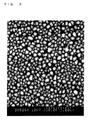
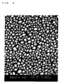
- the portion that appears black (background) is the surface of the undercoating, which is the base material, and the granular portion that appears white is the sheen of the metal In particles.
- Fig.2 shows the surface of the In coating of the example in Group 2 (which has an undercoating of SiO 2 a light transmittance of 4.02%, and an electrical resistance value of 6.38E+12 ⁇ / ⁇ ). An extremely fine and discontinuous sea-island structure has been established.
- Fig.3 shows the surface of the In coating of the comparative example (which has an undercoating of an acrylic coating material, a light transmittance of 3.99%, and an electrical resistance value of 3.26E+01 ⁇ / ⁇ ) .
- a structure has been established in which the organization is coarse and some parts are joined (continuous).
- Fig. 4 shows the surface of the In coating of the example in Group 3 (which has an undercoating of TiO 2 , a light transmittance of 3.92%, and an electrical resistance value of 5.46E+11 ⁇ / ⁇ ). Similar to the example in FIG. 2 described above, an extremely fine and discontinuous sea-island structure has been established.
- an In coating was deposited by using sputtering on an undercoating made by coating the base material with an inorganic coating material whose principal component was silicon.
- the In coating was deposited so as to form three layers having respective light transmittances of 8%, 14%, and 23% (all average values). As the light transmittance becomes higher, which means that as the coating becomes thinner, the electrical resistance tends to increase.
- an In coating was similarly deposited in three layers on an undercoating made by coating the base material with an organic coating that was a mixture of acrylic and polyester and one in which an In coating was similarly deposited in three layers directly on a glass base material were produced.
- the examples and the comparative examples at the same light transmittance were compared respectively, and for all of the light transmittances, it was confirmed that the electrical resistances of the In coating in the examples was high in comparison to the comparative examples in which an organic coating film was used. In addition, it was further confirmed that the electrical resistance of the examples was equal to or greater than in the comparative examples in which an inorganic glass base material was used as well. Thereby the effectiveness of the SiO 2 undercoating was confirmed.
- This example was produced by modifying Group 4 such that a Cr coating was deposited by using vacuum vapor deposition to attain a light transmittance of 26 to 29%.
- a Cr coating was similarly deposited on an undercoating that was formed by coating the base material with an acrylic coating material and one in which a Cr coating was similarly deposited directly on a PC base material were produced.
- the electrical resistance of the Cr coating in the example was high, and the effectiveness of the SiO 2 undercoating was thereby confirmed.
- This group consisted entirely of comparative examples. These comparative examples were produced by modifying Group 6 such that the undercoating was replaced by an undercoating made by coating the base material with an acrylic coating material and the hydrophilic property was similarly varied at three levels: high, medium, and low. Even when the hydrophilic property was varied, the electrical resistance of all of the comparative examples was low and no significant differences were found. It was thereby understood that the hydrophilic property was weakly related to the discontinuous structure.
- an In coating was deposited by vacuum vapor deposition on the undercoating formed by coating the base material with an amorphous TiO 2 inorganic coating material such that the light transmittance was somewhat less than 4%.
- an In coating was similarly deposited on an undercoating made by coating the base material with an acrylic coating material and one in which an In coating was similarly deposited directly on a PC base material were produced. Because the electrical resistance of the In coating in the example was high, the effectiveness of the TiO 2 undercoating was confirmed.
- the present invention provides a metallic coating having a sheen and discontinuous structure and a resin product having the metallic coating by using a physical vapor deposition method at high productivity and low cost.
Landscapes
- Chemical & Material Sciences (AREA)
- Chemical Kinetics & Catalysis (AREA)
- Engineering & Computer Science (AREA)
- Materials Engineering (AREA)
- Mechanical Engineering (AREA)
- Metallurgy (AREA)
- Organic Chemistry (AREA)
- Laminated Bodies (AREA)
- Physical Vapour Deposition (AREA)
Abstract
The present invention provides a metallic coating having a sheen and discontinuous structure and a resin product having the metallic coating by using a physical vapor deposition method at high productivity and low cost.
Description
- The present invention relates to a resin product having a metallic coating that has a sheen and a discontinuous structure, a manufacturing method for the same, and a deposition method for the metallic coating, and is used for a millimeter wave radar apparatus cover and other various uses.
- In order to warn a driver that the automobile is approaching an object in its vicinity, providing a millimeter wave radar apparatus for measuring distance on each part of an automobile, for example, behind the radiator grill, the side moldings, the back panels, and the like, is under study. However, in the case in which the radiator grill and the like are provided with a sheen by using a metallic coating, this metallic coating blocks or greatly attenuates the millimeter waves. Thus, the path of the millimeter waves of the radar apparatus must be covered by a radar apparatus cover that has a sheen and has millimeter wave transparency. In order for the metallic coating to be transparent to millimeter waves, a discontinuous structure is necessary. In this discontinuous structure, the metallic coating does not form one continuous surface, but instead it has a structure (sea-island structure) in which many fine metal particles are spread over the surface in a state in which they are slightly separated from each other or have portions thereof in contact so as to coalesce into islands.
- The following methods are conventionally known for forming metallic coatings having a sheen and a discontinuous structure by using a physical vapor deposition method. The industrial applicability of these methods has progressed with the goal of attaining, as coating characteristics, the effects of an improvement in corrosion resistance, conforming to stresses, and transparency to high frequency electromagnetic waves.
- (1) In many conventional methods, in order to cause the metallic coating to become discontinuous to a degree that does not lose the sheen, a physical vapor deposition method is used to form a metallic coating that has a sheen and a continuous structure, and subsequently, a post-processing treatment, for example, etching using masks, is applied. However, it cannot be said that this method is optimal in terms of the treatment costs.
- (2) In addition, a method has been reported in which the treatment is stopped in a state of an ultra-thin film before metallic coating formation by a physical vapor deposition method to obtain a discontinuous structure. However, in this method, a metallic sheen that is adequate in terms of external appearance cannot be obtained.
- (3) As a method for solving these problems, the formation of an In or Sn coating by using a physical vapor deposition method has been reported in the following patent documents: Japanese Examined Utility Model No.
JP-U-S63-30136 JP-A-H7-316782 PCT International Application No. 2001-526983 - (4) In addition, in Japanese Patent Application Publication No.
JP-A-H9-70920 - Thus, it is an object of the present invention to obtain a metallic coating that has a sheen and discontinuous structure at high productivity and low cost even when using a physical vapor deposition method.
- In order to solve the problems described above, the present invention employs the following means [1] to [3]:
- [1] A resin product which comprises a resin base material; an inorganic undercoating that comprises an inorganic compound deposited on the resin base material; and a metallic coating deposited on the inorganic undercoating by using a physical vapor deposition method, the metallic coating comprising at least one of chromium (Cr) and indium (In) and having a sheen and a discontinuous structure.
- [2] The manufacturing method for a resin product which comprises the steps of forming an inorganic undercoating that comprises an inorganic compound on the resin base material; and depositing a metallic coating on the inorganic undercoating by using a physical vapor deposition method, the metallic coating comprising at least one of Cr and In and having a sheen and a discontinuous structure.
- [3] A deposition method for a metallic coating which comprises the step of depositing a metallic coating on the inorganic undercoating by using a physical vapor deposition method, the metallic coating comprising at least one of Cr and In and having a sheen and a discontinuous structure.
- Each of the elements in these means is illustrated in the following examples.
- The form of the resin base material is not limited in particular, but a base board, a sheet material, a film and the like may be mentioned as examples. The resin for the base material is not limited in particular, but a thermoplastic resin is preferable, and PCs (polycarbonates), acrylic resins, polystyrenes, PVCs (polyvinyl chlorides), and polyurethanes may be mentioned as examples.
- The material for an inorganic undercoating that includes an inorganic compound is not limited in particular, but the following examples may be mentioned. Note that the inorganic undercoating may include small amounts (for example, 20 wt. % or less) of organic compounds in the inorganic compounds.
-
- Titanium compounds such as titanium oxide (TiO, TiO2, Ti3O5 and the like)
- Silicon compounds such as silicon oxide (SiO, SiO2 and the like), silicon nitride (Si3N4 and the like)
- Aluminum compounds such as aluminum oxide (Al2O3)
- Iron compounds such as iron oxide (Fe2O3)
- Cerium compounds such as ceric oxide (CeO)
- Zirconium compounds such as zirconium oxide (ZrO)
- Zinc compounds such as zinc sulfide (ZnS)
- A coating film made of an inorganic coating material in which silicon, amorphous TiO2 or the like (additionally, the metallic compounds illustrated above) is used as the principal component.
- The deposition method for the inorganic undercoating is not limited in particular, but in the case of a thin film made of the metallic compounds in (a) described above, a physical vapor deposition method may be mentioned as an example, and in the case of a coating film made of the inorganic coating materials in (b) described above, a spray coating or the like may be mentioned as an example. The physical vapor deposition method is not particular limited, but a vacuum vapor deposition method, molecular beam deposition, ion plating, ion beam deposition, sputtering, and the like may be mentioned as examples. In the case of a coating film made of an inorganic coating material, baking after coating is preferable.
- The coating thickness of the inorganic undercoating is not limited in particular, but in the case of a physical vapor deposition method using any of the metallic compounds in (a) described above, about 7 to 100 nm is preferable, and in the case of a spray coating using any of the coating materials in (b) described above, about 0.5 to 3 µm is preferable. It is considered that the function of providing the metallic coating with a discontinuous structure is present even at less than 7 nm, but the continuity (leveling) of the undercoating itself is frequently poor, and the original object of covering the resin base material with an inorganic material becomes difficult to attain.
- The thickness of the metallic coating is not limited inparticular, but 10 to 100 nm is preferable. The reason for this is that when the coating thickness is less than 10 nm, the sheen tends to decrease, while the coating thickness exceeds 100 nm, the electrical resistance tends to become low, and for example, the millimeter wave transparency tends to degrade.
- The physical vapor depositionmethod, which is a deposition method for a metallic coating, is not limited in particular, but a vacuum vapor deposition method, molecular beam deposition, ion plating, ion beam deposition, sputtering and the like may be mentioned as examples.
- Preferably, a protective film is formed on the metallic coating in order to protect this metallic coating. In the case in which the lower surface side of the resin base material is a design surface, a press coating film or the like may be formed as a protective filmonthemetalliccoating. Furthermore, aresinbackingmaterial may be injection molded onto the press coating. In contrast, in the case in which the upper surface side of the metallic coating is a design surface, a clear top coating film or the like may be formed as a protective film on the metallic coating.
- Because the metallic coating is discontinuous, the metallic coating has a high electrical resistance. Thereby, properties such as millimeter wave transparency and a lightning protecting capacity are present. Furthermore, because of its discontinuity, the spread of corrosion is suppressed, so that corrosion resistance is present. In addition, the discontinuous metallic coating readily conforms to the curved surfaces of the resin base material. The types (uses) of resin products that can be realized due to having these qualities are not limited in particular, but the following may be mentioned as examples:
- (a) Use in a millimeter wave radar apparatus cover may be mentioned as an example of the use for taking advantage of the millimeter wave transparency. The part to which this cover is applied is not limited in particular, but use in an external application product for an automobile is preferable, and in particular, suitable for a radiator grill, a grill cover, sidemoldings, backpanels, bumpers, emblems, and the like.
- (b) Use in an umbrella or the like may be mentioned as an example of the use for taking advantage of the lightning protecting capacity.
- (c) Use in a printed circuit board may be mentioned as an example of the use for taking advantage of the property that only treated areas are electrically insulating.
- (d) Use in exterior parts of an automobile such as emblems, radiator grills, and shiny moldings may be mentioned as an example of the use for taking advantage of the corrosion resistance characteristic.
- (e) Use in elastic shiny moldings may be mentioned as an example of the use for taking advantage of conforming to curved surfaces.
- (f) In addition, use in containers for use in a microwave oven may be mentioned as an example of the use for taking advantage of the infrared transparency.
- When the metallic coating is deposited by a physical vapor deposition method either directly on a resin base material or over an organic undercoating, this metallic coating has a sheen, but also acquires a continuous structure. In contrast, it has been turned out that when the metallic coating is deposited by a physical vapor deposition method on an inorganic undercoating, the metallic coating readily acquires a sheen and a discontinuous structure (a sea-island structure). It is conjectured that this occurs due to the following mechanism.
- It is considered that an important factor is that the metal particles that have landed on the resin base material select a Volmer-Weber growth mode if they have a large degree of freedom to migrate on this resin base material, and in the end readily acquire the discontinuous structure. Alternatively, it is considered that if the metal particles have no degree of freedom to migrate, the metal particles stop at the location where they have landed, and select a flat Frank-Von der Merwe growth mode, and in the end readily acquire a continuous structure. For example, depositing the metallic coating by using a sputtering method, in which the energy that the metal particles acquire is higher than the energy acquired by using a vacuum vapor deposition method, readily yields a continuous structure. It is considered that the reason for this is that the metal particles are readily stuck into the resin base material. In addition, when the temperature of the resin base material is made high, the metallic coating readily acquires a discontinuous structure in addition to growing into spheres. It is considered that the reason for this is that the metal particles do not stop where they land, and they acquire the energy for escaping from the binding force that would adhere them.
- In a physical vapor deposition method, the metal particles land on the base material in a reactive state (a pure metal atomic state) that would not allow them to be ordinarily present at atmospheric pressure (in the presence of oxygen). The metal particles immediately react to form compounds when oxygen, nitrogen or the like are present in the vicinity. In contrast, when considering organic and inorganic base material surfaces, generally an organic network of C-C, C-O, C-H or the like are chemically more unstable than an inorganic network of Si-O, Ti-O or the like. In fact, when comparing weather resistance capacity, alkali resistance, and acid resistance capacity, among the inorganic coating materials and organic coating materials, clearly the inorganic coatings have a lower degree of degradation, and this means that they are chemically stable, that is, the inorganic coatings form an unreactive and durable network.
- Therefore, it is considered that there is the possibility that some sort of chemical interference (an absorbing action or an affinity) is acting between the metal particles and the resin base material, and in particular, operating on the metal particles that first land on the resin base material, and that this acts to inhibit the diffusion movement of the metal particles over the resin base material. This inhibiting is significant when the base material surface is organic and in an active state. Thus, it is considered that by making the base material surface inorganic and in an unreactive state, this inhibiting will be decreased, the sea-island morphology will be promoted, and finally a discontinuous structure will be obtained.
- According to the present invention, a metallic coating that has a sheen and has a discontinuous structure can be obtained at high productivity and low cost even by a physical vapor deposition method.
-
- FIG. 1 is a cross-sectional view showing the resin product in an example of the present invention,
- FIG. 2 is a microscopic photograph of the In coating of the example in
Group 2, which has an undercoating of SiO2, and a light transmittance of 4.02%, - FIG. 3 is a microscopic photograph of the In coating of the comparative example in
Group 2, which has an undercoating of an acrylic coating material, and a light transmittance of 3.99%, and - FIG. 4 is a microscopic photograph of the In coating of the example in Group 3, which has an undercoating of TiO2, and a light transmittance of 3.92%.
- A resin product 10 (for example, a millimeter wave radar apparatus cover) shown in FIG. 1 includes a plate-shaped
resin base material 11; aninorganic undercoating 12 that includes inorganic compounds that are deposited on theresin base material 11; and ametallic coating 13 that has a sheen and has a discontinuous structure, and has been deposited onto theinorganic undercoating 12 by using a physical vapor deposition method. On themetallic coating 13, a top coating film and a press coating film, or the like are formed as a protective film. - This
resin product 10 is produced by the steps described below. Theresin base material 11 has a plate-shape that is 5 mm thick, and is made of, for example, a PC (polycarbonate). - As shown in the following TABLE 1, in the
inorganic undercoating 12 in each of the examples, the thin film made of a metallic compound is deposited by using a vacuum vapor deposition, and a coating film made of an inorganic coating material is deposited by using a spray coating. - As shown in the following TABLE 1, the metallic coating of the examples is one in which Cr or In is deposited by vacuum vapor deposition or sputtering.
- The conditions for the vacuum vapor deposition are not limited in particular, but in the following examples, a vacuum vapor deposition apparatus made by Shincron was used, electron beam heating was used as a heating method, the attained degree of vacuum was 5.0×10⁻³ Pa, and the deposition was carried out with the chamber at room temperature.
- The conditions for the sputtering are not limited in particular, but in the following examples, a sputtering apparatus made by Kawai Optics was used, and using a DC magnetron method, the attained degree of vacuum was 5.0×10⁻³ Pa, and the deposition was carried out with the chamber at room temperature.
- As shown in the following TABLE 1, resin product samples for the examples and the comparative examples of groups No. 1 to No. 10 were produced.


- In this example, a Cr coating was deposited by using a vacuum vapor deposition on an undercoating of SiO2 that was deposited by using a vacuum vapor deposition so as to attain a light transmittance of 26 to 29%. As comparative examples, one in which a Cr coating was similarly deposited directly on a PC base material and one in which a Cr coating was similarly deposited on an undercoating made by coating the base material with a polyester coating material were produced. Because the electrical resistance of the Cr coating in the example was high (a discontinuous structure), the effectiveness of the SiO2 undercoating was confirmed.
- In this example, an In coating was deposited by using a vacuum vapor deposition on an undercoating of SiO2 that was deposited by using a vacuum vapor deposition such that the light transmittance was about 4%. As comparative examples, one in which an In coating was similarly deposited directly on a PC base material and one in which an In coating was similarly deposited on an undercoating made by coating the base material with an acrylic coating material were produced. Because the electrical resistance of the In coating in the example was high, the effectiveness of the SiO2 undercoating was confirmed.
- This example was produced by modifying the example in
Group 2 by changing the undercoating to TiO2 and changing the light transmittance of the In coating. Because the electrical resistance of the In coating in the example was high, the effectiveness of the TiO2 undercoating was confirmed. - The morphology (fine structure) of the deposited In coating of these
Groups 2 and 3 was observed by using a microscope. In FIG. 2 to FIG. 4, the portion that appears black (background) is the surface of the undercoating, which is the base material, and the granular portion that appears white is the sheen of the metal In particles. - Fig.2 shows the surface of the In coating of the example in Group 2 (which has an undercoating of SiO2 a light transmittance of 4.02%, and an electrical resistance value of 6.38E+12 Ω/□). An extremely fine and discontinuous sea-island structure has been established.
- Fig.3 shows the surface of the In coating of the comparative example (which has an undercoating of an acrylic coating material, a light transmittance of 3.99%, and an electrical resistance value of 3.26E+01Ω/□) . In comparison to the example in FIG. 2 described above, a structure has been established in which the organization is coarse and some parts are joined (continuous).
- Fig. 4 shows the surface of the In coating of the example in Group 3 (which has an undercoating of TiO2, a light transmittance of 3.92%, and an electrical resistance value of 5.46E+11Ω/□). Similar to the example in FIG. 2 described above, an extremely fine and discontinuous sea-island structure has been established.
- In this example, an In coating was deposited by using sputtering on an undercoating made by coating the base material with an inorganic coating material whose principal component was silicon. The In coating was deposited so as to form three layers having respective light transmittances of 8%, 14%, and 23% (all average values). As the light transmittance becomes higher, which means that as the coating becomes thinner, the electrical resistance tends to increase. As comparative examples, one in which an In coating was similarly deposited in three layers on an undercoating made by coating the base material with an organic coating that was a mixture of acrylic and polyester and one in which an In coating was similarly deposited in three layers directly on a glass base material were produced. The examples and the comparative examples at the same light transmittance were compared respectively, and for all of the light transmittances, it was confirmed that the electrical resistances of the In coating in the examples was high in comparison to the comparative examples in which an organic coating film was used. In addition, it was further confirmed that the electrical resistance of the examples was equal to or greater than in the comparative examples in which an inorganic glass base material was used as well. Thereby the effectiveness of the SiO2 undercoating was confirmed.
- This example was produced by modifying Group 4 such that a Cr coating was deposited by using vacuum vapor deposition to attain a light transmittance of 26 to 29%. As comparative examples, one in which a Cr coating was similarly deposited on an undercoating that was formed by coating the base material with an acrylic coating material and one in which a Cr coating was similarly deposited directly on a PC base material were produced. The electrical resistance of the Cr coating in the example was high, and the effectiveness of the SiO2 undercoating was thereby confirmed.
- These examples were produced by modifying Group 4 such that the hydrophilic property of the undercoating, which was made by coating the base material with an inorganic coating whose principal component was silicon, was varied at three levels: high, medium, and low. Even when the hydrophilic property was varied, the electrical resistance of all the examples was high and no significance differences were found. It was thereby understood that the hydrophilic property was weakly related to the discontinuous structure.
- This group consisted entirely of comparative examples. These comparative examples were produced by modifying Group 6 such that the undercoating was replaced by an undercoating made by coating the base material with an acrylic coating material and the hydrophilic property was similarly varied at three levels: high, medium, and low. Even when the hydrophilic property was varied, the electrical resistance of all of the comparative examples was low and no significant differences were found. It was thereby understood that the hydrophilic property was weakly related to the discontinuous structure.
- In this example, an In coating was deposited by vacuum vapor deposition on the undercoating formed by coating the base material with an amorphous TiO2 inorganic coating material such that the light transmittance was somewhat less than 4%. As comparative examples, one in which an In coating was similarly deposited on an undercoating made by coating the base material with an acrylic coating material and one in which an In coating was similarly deposited directly on a PC base material were produced. Because the electrical resistance of the In coating in the example was high, the effectiveness of the TiO2 undercoating was confirmed.
- In this example, after forming the undercoating by coating the base material with an inorganic silicon coating material, the undercoating underwent treatment in three drying conditions; 1) drying for 6 hours at room temperature; 2) baking for 2 hours at 80°C; and 3) baking for 4 hours at 150°C.
- Subsequently, an In coating was deposited by vacuum vapor deposition on these undercoatings. As the temperature during baking and drying increased, the electrical resistance of the In coating also increased. Thereby, the presence of the effect was confirmed under drying conditions.
- This group consisted entirely of comparative examples. In these comparative examples, the case in which a rigid acrylic hard coating was used in the undercoating was compared to the case of a normal acrylic coating material and the case of a PC base material to ascertain whether or not there was any change. However, it was found that an acrylic material was not effective even when hardened.
- Next, as shown in TABLE 2, from experiment No. 1, it was confirmed that even when the SiO2 undercoating deposited by vacuum vapor deposition was an extremely thin 7 nm, the electrical resistance of the In coating deposited thereon by using vacuum vapor deposition was sufficiently high, and that this undercoating was effective. It is considered that this effect would be present even if the undercoating were less than 7 nm, but because of control difficulties related to uniform continuous coating production, this is not practically useful.
TABLE 2 Experiment No. Comparative Example 1 2 3 4 5 Coating Structure Base material PC ← ← Glass Material ← ← Undercoating None SiO2 vapor deposition at 7 nm Si3N4 vapor deposition at 10 nm Acrylic 30/ Silicon 100 coating Acrylic 10/ Silicon 100 coating Acrylic 0/ Silicon 100 coating Metallic Coating In vapor deposition at 60nm ← ← ← ← ← Result Light Transmittance (@550nm) 3.89% 4.47% 6.78% 2.45% 2.61% 2.42% Electrical Resistance (Ω/□) 3.26E+01 7.31E+12 2.96E+12 1.53E+08 2.07E+10 3.50E+10 - In addition, as shown in TABLE 2, from experiment No. 2, an effectiveness similar to that of SiO2 was confirmed for the Si3N4 undercoating deposited by using vacuum vapor deposition.
- Furthermore, as shown in TABLE 2, in experiments No. 3 to No. 5, an undercoating was coated and formed by using a coating material in which the acrylic resin coating material was mixed in three steps of 50 mass units, 10 mass units, and 0 mass units per 100 mass units of inorganic silicon resin coating material, and the effect of an organic material that was mixed into the inorganic undercoating on the electrical resistance value of the above In coating was investigated. As a result, it was determined that the electrical resistance value of the In coating decreased as the mixing amount of the acrylic resin coating material increased. Based on this result, the conjecture described above about the mechanism by which the metallic coating acquires a discontinuous structure (sea-island structure) was confirmed. Specifically, the mechanism by which an inorganic undercoating promotes the formation of a discontinuous structure and an organic undercoating hinders formation of a discontinuous structure was confirmed.
- Note that the present invention is not limited by the examples described above, and the present invention may be practiced after suitable modifications within a range that does not depart from the spirit of the present invention.
- The present invention provides a metallic coating having a sheen and discontinuous structure and a resin product having the metallic coating by using a physical vapor deposition method at high productivity and low cost.
Claims (18)
- A resin product having a resin base material and a metallic coating, characterized in that;
the resin product comprises an inorganic undercoating that comprises an inorganic compound deposited on the resin base material;
the metallic coating comprises at least one of chromium and indium and have a sheen and a discontinuous structure; and
the metallic coating is deposited on the inorganic undercoating by using a physical vapor deposition. - The resin product according to claim 1, wherein the inorganic undercoating is a thin film made of a metallic compound.
- The resin product according to claim 2, wherein the metallic compound comprises at least one of a silicon compound and a titanium compound.
- The resin product according to claim 1, wherein the inorganic undercoating is a coating filmmade of an inorganic coating material.
- The resin product according to claim 4, wherein the inorganic coating material comprises at least one of an inorganic silicon coating material and an amorphous titanium oxide inorganic coating material.
- The resin product according to claim 4, wherein the coating film made of the inorganic coating material is baked after coating.
- The manufacturing method for a resin product, characterized in that the method comprises the steps of:forming an inorganic undercoating that comprises an inorganic compound on the resin base material; anddepositing a metallic coating on the inorganic undercoating by using a physical vapor deposition method, said metallic coating comprising at least one of chromium and indium and having a sheen and a discontinuous structure.
- The manufacturing method for a resin product according to claim 7, wherein the inorganic undercoating is a thin film made of a metallic compound.
- The manufacturing method for a resin product according to claim 8, wherein the metallic compound comprises at least one of a silicon compound and a titanium compound.
- The manufacturing method for a resin product according to claim 7, wherein the inorganic undercoating is a coating film made of an inorganic coating material.
- The manufacturing method for a resin product according to claim 10, wherein the inorganic coating material comprises at least one of an inorganic silicon coating material and an amorphous titanium oxide inorganic coating material.
- The manufacturing method for a resin product according to claim 10, wherein the coating film made of the inorganic coating material is baked after coating.
- A deposition method for a metallic coating, characterized in that the method comprises the step of:depositing a metallic coating on the inorganic undercoating by using a physical vapor deposition method, said metallic coating comprising at least one of chromium and indium and having a sheen and a discontinuous structure.
- The deposition method for a metallic coating according to claim 13, wherein the inorganic undercoating is a thin film made of a metallic compound.
- The deposition method for a metallic coating according to claim 14, wherein the metallic compound comprises at least one of a silicon compound and a titanium compound.
- The deposition method for a metallic coating according to claim 13, wherein the inorganic undercoating is a coating film made of an inorganic coating material.
- The deposition method for a metallic coating according to claim 16, wherein the inorganic coating material comprises at least one of an inorganic silicon coating material and an amorphous titanium oxide inorganic coating material.
- The deposition method for a metallic coating according to claim 16, wherein the coating film made of the inorganic coating material is baked after coating.
Applications Claiming Priority (2)
| Application Number | Priority Date | Filing Date | Title |
|---|---|---|---|
| JP2005317070 | 2005-10-31 | ||
| JP2006227916A JP4706596B2 (en) | 2005-10-31 | 2006-08-24 | Resin product, method for producing the same, and method for forming metal film |
Publications (1)
| Publication Number | Publication Date |
|---|---|
| EP1788111A2 true EP1788111A2 (en) | 2007-05-23 |
Family
ID=37685694
Family Applications (1)
| Application Number | Title | Priority Date | Filing Date |
|---|---|---|---|
| EP20060122842 Withdrawn EP1788111A2 (en) | 2005-10-31 | 2006-10-24 | Resin product, production method for the same, and deposition method for a metallic coating |
Country Status (3)
| Country | Link |
|---|---|
| US (1) | US7846498B2 (en) |
| EP (1) | EP1788111A2 (en) |
| JP (1) | JP4706596B2 (en) |
Cited By (2)
| Publication number | Priority date | Publication date | Assignee | Title |
|---|---|---|---|---|
| CN111839360A (en) * | 2020-06-22 | 2020-10-30 | 珠海格力电器股份有限公司 | Sweeper data processing method, device, device and computer readable medium |
| EP3804982A4 (en) * | 2018-06-01 | 2022-03-02 | Dai Nippon Printing Co., Ltd. | METALLIC DECORATIVE ELEMENT AND METALLIC DECORATIVE CAST BODY USING THE SAME |
Families Citing this family (32)
| Publication number | Priority date | Publication date | Assignee | Title |
|---|---|---|---|---|
| JP2008080712A (en) * | 2006-09-28 | 2008-04-10 | Toyoda Gosei Co Ltd | Resin product which has metal film having brightness and discontinuous structure |
| JP2009078458A (en) * | 2007-09-26 | 2009-04-16 | Toyoda Gosei Co Ltd | Apparatus housing and apparatus decoration with interference color film |
| DE102008034991A1 (en) * | 2008-07-25 | 2010-01-28 | Leybold Optics Gmbh | Method for producing a layer system on a substrate, and layer system |
| JP4881984B2 (en) * | 2009-08-28 | 2012-02-22 | 株式会社ファルテック | Manufacturing method of radome |
| JP5817195B2 (en) * | 2011-04-19 | 2015-11-18 | アイシン精機株式会社 | Door opener |
| KR101745053B1 (en) * | 2014-02-13 | 2017-06-08 | 현대자동차주식회사 | Surface treatment of the metallic member using on transmission path of the radar and a method of manufacturing it |
| JP6566750B2 (en) * | 2015-07-02 | 2019-08-28 | Cbc株式会社 | Method for forming discontinuous metal film |
| US9828036B2 (en) | 2015-11-24 | 2017-11-28 | Srg Global Inc. | Active grille shutter system with integrated radar |
| JP2018035402A (en) * | 2016-08-31 | 2018-03-08 | 株式会社ファルテック | Radar cover manufacturing method |
| US10090588B2 (en) | 2016-09-26 | 2018-10-02 | Srg Global Inc. | Selectively chrome plated vehicle radome and vehicle radiator grille and methods of manufacturing |
| JP6400062B2 (en) | 2016-10-24 | 2018-10-03 | 日東電工株式会社 | Electromagnetic wave transmitting metallic luster member, article using the same, and metallic thin film |
| KR101856441B1 (en) * | 2017-09-29 | 2018-05-10 | 인탑스 주식회사 | Manufacturing method emblem are built sensor |
| JP7516707B2 (en) | 2018-01-12 | 2024-07-17 | 日東電工株式会社 | Radio wave-transmitting metallic glossy member, article using same, and method for manufacturing same |
| WO2019139122A1 (en) | 2018-01-12 | 2019-07-18 | 日東電工株式会社 | Radio wave-transmitting lustrous metal member, article using same, and method for producing same |
| JP7332298B2 (en) * | 2018-01-12 | 2023-08-23 | 日東電工株式会社 | Electromagnetic wave permeable metallic luster film |
| JP6980537B2 (en) * | 2018-01-12 | 2021-12-15 | 株式会社ウェーブロック・アドバンスト・テクノロジー | Metal layer holding film, metal-like decorative sheet intermediate, metal-like decorative sheet, extrusion laminated body, metal-like molded body, injection molded body, manufacturing method of metal-like molded body, manufacturing method of injection molded body and extrusion laminating How to make a body |
| JP7319080B2 (en) | 2018-04-23 | 2023-08-01 | 日東電工株式会社 | Electromagnetic wave transparent metallic luster article and metal thin film |
| WO2019208490A1 (en) | 2018-04-23 | 2019-10-31 | 日東電工株式会社 | Electromagnetic wave-permeable metal glossy article and method for manufacturing same |
| JP2019188809A (en) | 2018-04-23 | 2019-10-31 | 日東電工株式会社 | Electromagnetic wave transmissible metallic sheen article |
| KR20210005585A (en) | 2018-04-23 | 2021-01-14 | 닛토덴코 가부시키가이샤 | Electromagnetic wave-transmitting metallic luster article, and decorative member |
| CN112020424A (en) | 2018-04-23 | 2020-12-01 | 日东电工株式会社 | Electromagnetic wave transmitting metallic luster article |
| JP7319077B2 (en) | 2018-04-23 | 2023-08-01 | 日東電工株式会社 | Electromagnetic wave transparent metallic luster article and metal thin film |
| JP7003827B2 (en) * | 2018-04-25 | 2022-01-21 | 豊田合成株式会社 | Bright products |
| WO2020046087A1 (en) | 2018-08-31 | 2020-03-05 | 주식회사 엘지화학 | Method for producing decorative member film |
| KR102507549B1 (en) | 2018-08-31 | 2023-03-07 | 주식회사 엘지화학 | Manufacturing method for decoration element and decoration element |
| KR102474038B1 (en) | 2018-08-31 | 2022-12-02 | 주식회사 엘지화학 | Manufacturing method for decoration element film |
| WO2020067052A1 (en) * | 2018-09-25 | 2020-04-02 | 積水化学工業株式会社 | Radio wave permeable body |
| DE102019102657A1 (en) * | 2019-02-04 | 2020-08-06 | Bayerische Motoren Werke Aktiengesellschaft | Radio-frequency permeable component and method for producing the same |
| JP6736105B1 (en) * | 2019-08-27 | 2020-08-05 | 柿原工業株式会社 | Radio-wave transparent film forming method by insulating chrome sputtering and smart entry unlocking/locking structure resin molded product |
| JP6736104B1 (en) * | 2019-08-27 | 2020-08-05 | 柿原工業株式会社 | Radio-wave transparent film forming method by insulating chrome sputtering and smart entry unlocking/locking structure resin molded product |
| WO2021182380A1 (en) * | 2020-03-09 | 2021-09-16 | 日東電工株式会社 | Electromagnetic-wave-transmissive laminated member and method for manufacturing same |
| JP7316671B2 (en) * | 2020-11-17 | 2023-07-28 | 尾池工業株式会社 | Scale-like pigment, paint, and painted object having millimeter wave transparency |
Family Cites Families (14)
| Publication number | Priority date | Publication date | Assignee | Title |
|---|---|---|---|---|
| JPH0818094B2 (en) | 1986-07-23 | 1996-02-28 | 株式会社古河テクノマテリアル | Method for manufacturing shape memory alloy wire compact |
| US5468518A (en) | 1994-05-25 | 1995-11-21 | Davidson Textron Inc. | Combined primer/basecoat island coating system |
| JP3839096B2 (en) | 1995-06-30 | 2006-11-01 | 豊田合成株式会社 | Soft brightening product |
| JP3291222B2 (en) * | 1997-05-19 | 2002-06-10 | トヨタ自動車株式会社 | Soft brightening products |
| WO1999033649A1 (en) | 1997-12-31 | 1999-07-08 | Textron Systems Corporation | Metallized sheeting, composites, and methods for their formation |
| DE19819709C2 (en) * | 1998-05-02 | 2000-05-25 | Daimler Chrysler Ag | Method for producing a radome for a distance warning radar and radome for a distance warning radar |
| JP2000344032A (en) * | 1999-06-08 | 2000-12-12 | Nissan Motor Co Ltd | Grill cover structure |
| US6767589B1 (en) * | 1999-10-12 | 2004-07-27 | Toray Composites (America), Inc. | Method for metal coating a flywheel rim |
| JP3581081B2 (en) * | 2000-07-11 | 2004-10-27 | リンテック株式会社 | Light-transmitting pressure-sensitive adhesive sheet for heat transfer image formation and light-transmitting decorative pressure-sensitive adhesive sheet |
| JP4099946B2 (en) * | 2001-01-11 | 2008-06-11 | 株式会社ファルテック | Method for producing molded product exhibiting metallic brilliant color |
| JP3568493B2 (en) * | 2001-06-18 | 2004-09-22 | 日本写真印刷株式会社 | Infrared transmission cover panel, decorative sheet for infrared transmission cover panel |
| JP2005249773A (en) * | 2004-02-02 | 2005-09-15 | Toyota Motor Corp | Molded product for beam path of radar equipment |
| JP3659354B1 (en) * | 2004-02-02 | 2005-06-15 | セイコーエプソン株式会社 | Decorative product, method of manufacturing decorative product, and watch |
| JP2006117048A (en) * | 2004-10-20 | 2006-05-11 | Toyota Motor Corp | Bright decorative molded product and molded product for radar device beam path |
-
2006
- 2006-08-24 JP JP2006227916A patent/JP4706596B2/en active Active
- 2006-10-24 US US11/585,148 patent/US7846498B2/en active Active
- 2006-10-24 EP EP20060122842 patent/EP1788111A2/en not_active Withdrawn
Cited By (4)
| Publication number | Priority date | Publication date | Assignee | Title |
|---|---|---|---|---|
| EP3804982A4 (en) * | 2018-06-01 | 2022-03-02 | Dai Nippon Printing Co., Ltd. | METALLIC DECORATIVE ELEMENT AND METALLIC DECORATIVE CAST BODY USING THE SAME |
| US11827762B2 (en) | 2018-06-01 | 2023-11-28 | Dai Nippon Printing Co., Ltd. | Metallic decorative member, and metallic decorative molded body using same |
| CN111839360A (en) * | 2020-06-22 | 2020-10-30 | 珠海格力电器股份有限公司 | Sweeper data processing method, device, device and computer readable medium |
| CN111839360B (en) * | 2020-06-22 | 2021-09-14 | 珠海格力电器股份有限公司 | Data processing method, device and equipment of sweeper and computer readable medium |
Also Published As
| Publication number | Publication date |
|---|---|
| US20070098967A1 (en) | 2007-05-03 |
| US7846498B2 (en) | 2010-12-07 |
| JP4706596B2 (en) | 2011-06-22 |
| JP2007144988A (en) | 2007-06-14 |
Similar Documents
| Publication | Publication Date | Title |
|---|---|---|
| US7846498B2 (en) | Resin product, production method for the same, and deposition method for a metallic coating | |
| KR20010042939A (en) | Transparent conductive laminate, its manufacturing method, and display comprising transparent conductive laminate | |
| EP0871792B1 (en) | Process for coating a substrate with titanium dioxide | |
| DE60318632T2 (en) | Thin film coating with a transparent primer layer | |
| EP0751235B1 (en) | Flexible metallized products and process for producing the same | |
| CA2526216A1 (en) | Appliance with coated transparency | |
| EP1962109A2 (en) | Glass sheet with antireflection film and laminated glass for windows | |
| US20110151246A1 (en) | Stone agglomerate slab or flag with tio2 or zno coating | |
| EP1923362A1 (en) | Infrared reflective glass plate and laminated glass for vehicle window | |
| US7722963B2 (en) | Resin product having a metallic coating | |
| EP3355408B1 (en) | Stacked body | |
| RU2481364C2 (en) | Intermediate layers providing improved top layer functionality | |
| CN102804390A (en) | Silicon thin-film solar cells with improved undercoating | |
| JP5061539B2 (en) | Resin product, method for producing the same, and method for forming metal film | |
| TW201945176A (en) | Electromagnetic-wave-permeable metallic-luster article, and decorative member | |
| RU2669408C2 (en) | Method of manufacturing of thermally processed coated product with the use of carbon coating and protective film | |
| US5714268A (en) | Coated solar protection glazing | |
| JP3501820B2 (en) | Transparent conductive film with excellent flexibility | |
| TWI869564B (en) | Electromagnetic wave permeable multilayer structure and manufacturing method thereof | |
| KR100963875B1 (en) | Method for coating thin film using an alloy of silicon and aluminium | |
| CN112020424A (en) | Electromagnetic wave transmitting metallic luster article | |
| KR102361847B1 (en) | Hard coat film with optical adjustment layer for transparent conductive film and transparent conductive film | |
| TW202003233A (en) | Electromagnetic wave transmissive metallic luster product and metal thin film | |
| EP4079513A1 (en) | Transparent substrate provided with multilayer film | |
| DE102007033665A1 (en) | Method for producing a layer system on a dielectric substrate having a first reflecting metal layer and a layer structure, comprises applying the first metal layer on the substrate by a vacuum coating process |
Legal Events
| Date | Code | Title | Description |
|---|---|---|---|
| PUAI | Public reference made under article 153(3) epc to a published international application that has entered the european phase |
Free format text: ORIGINAL CODE: 0009012 |
|
| 17P | Request for examination filed |
Effective date: 20061024 |
|
| AK | Designated contracting states |
Kind code of ref document: A2 Designated state(s): AT BE BG CH CY CZ DE DK EE ES FI FR GB GR HU IE IS IT LI LT LU LV MC NL PL PT RO SE SI SK TR |
|
| AX | Request for extension of the european patent |
Extension state: AL BA HR MK YU |
|
| STAA | Information on the status of an ep patent application or granted ep patent |
Free format text: STATUS: THE APPLICATION HAS BEEN WITHDRAWN |
|
| 18W | Application withdrawn |
Effective date: 20100811 |