EP1787738B1 - Joining method - Google Patents
Joining method Download PDFInfo
- Publication number
- EP1787738B1 EP1787738B1 EP20050025086 EP05025086A EP1787738B1 EP 1787738 B1 EP1787738 B1 EP 1787738B1 EP 20050025086 EP20050025086 EP 20050025086 EP 05025086 A EP05025086 A EP 05025086A EP 1787738 B1 EP1787738 B1 EP 1787738B1
- Authority
- EP
- European Patent Office
- Prior art keywords
- hole
- joining
- section
- fixing
- sections
- Prior art date
- Legal status (The legal status is an assumption and is not a legal conclusion. Google has not performed a legal analysis and makes no representation as to the accuracy of the status listed.)
- Expired - Fee Related
Links
Images


Classifications
-
- B—PERFORMING OPERATIONS; TRANSPORTING
- B21—MECHANICAL METAL-WORKING WITHOUT ESSENTIALLY REMOVING MATERIAL; PUNCHING METAL
- B21D—WORKING OR PROCESSING OF SHEET METAL OR METAL TUBES, RODS OR PROFILES WITHOUT ESSENTIALLY REMOVING MATERIAL; PUNCHING METAL
- B21D39/00—Application of procedures in order to connect objects or parts, e.g. coating with sheet metal otherwise than by plating; Tube expanders
- B21D39/03—Application of procedures in order to connect objects or parts, e.g. coating with sheet metal otherwise than by plating; Tube expanders of sheet metal otherwise than by folding
- B21D39/031—Joining superposed plates by locally deforming without slitting or piercing
- B21D39/032—Joining superposed plates by locally deforming without slitting or piercing by fitting a projecting part integral with one plate in a hole of the other plate
Description
Die Erfindung betrifft ein Verfahren zum Fixieren von aufeinander liegenden oder aneinander anliegenden Fixierabschnitten von mindestens zwei Teilen, insbesondere Blechteilen, relativ zueinander, wobei die Fixierabschnitte durch einen Stempel verformt werden, gemäß dem Oberbegriff des Anspruchs 1 (siehe z.B.
Es ist bekannt, Fixierabschnitte von Blechteilen zu verschweißen, zu vernieten oder zu verstemmen. Darüber hinaus ist aus der deutschen Offenlegungsschrift
Aufgabe der Erfindung ist es, das Fixieren von aufeinander liegenden oder aneinander anliegenden Fixierabschnitten von mindestens zwei Teilen, insbesondere Blechteilen, relativ zueinander zu vereinfachen, wobei die Fixierabschnitte durch einen Stempel verformt werden.The object of the invention is to simplify the fixing of superimposed or adjoining fixing sections of at least two parts, in particular sheet metal parts, relative to each other, wherein the fixing sections are deformed by a punch.
Die Aufgabe ist durch ein Verfahren gemäß Anspruch 1 gelöst. Das erfindungsgemäße Verfahren liefert den Vorteil, dass der Fixierabschnitt ohne Loch auch nach dem Verformen eine hohe Dichtigkeit aufweist. Das Loch liefert unter anderem den Vorteil, dass ein dem Stempel gegenüberliegender Gegenhalter, der auch als Matrize bezeichnet wird, mit einer ebenen Oberfläche ohne Vertiefungen ausgestattet sein kann.The object is achieved by a method according to
Ein bevorzugtes Ausführungsbeispiel des Verfahrens ist dadurch gekennzeichnet, dass das Loch vor dem Verformen der Fixierabschnitte auf der dem anderen Fixierabschnitt zugewandten Seite mit einer Fase versehen wird. Durch die Fase wird die Lagefindung mit dem Stempel vereinfacht. Dadurch wird die Prozesssicherheit erhöht.A preferred embodiment of the method is characterized in that the hole is provided with a chamfer on the side facing the other fixing section prior to the deformation of the fixing sections. The chamfer makes finding the position with the punch easier. This increases the process reliability.
Ein weiteres bevorzugtes Ausführungsbeispiel des Verfahrens ist dadurch gekennzeichnet, dass der Fixierabschnitt mit dem Loch eine größere Dicke aufweist als der andere Fixierabschnitt. Das Fügen der Fixierabschnitte erfolgt durch Verstemmen des dünneren Fixierabschnitts in das Loch in dem dickeren Fixierabschnitt.A further preferred embodiment of the method is characterized in that the fixing section with the hole has a greater thickness than the other fixing section. The joining of the fixing sections takes place by caulking the thinner fixing section into the hole in the thicker fixing section.
Ein weiteres bevorzugtes Ausführungsbeispiel des Verfahrens ist dadurch gekennzeichnet, dass der Fixierabschnitt mit dem Loch etwa zweimal bis dreimal so dick wie der andere Fixierabschnitt ist. Vorzugsweise ist der Fixierabschnitt mit dem Loch etwa 2,5 mal so dick wie der andere Fixierabschnitt.A further preferred embodiment of the method is characterized in that the fixing portion with the hole is about twice to three times as thick as the other fixing portion. Preferably, the fixing portion with the hole is about 2.5 times as thick as the other fixing portion.
Ein weiteres bevorzugtes Ausführungsbeispiel des Verfahrens ist dadurch gekennzeichnet, dass das Loch einen kreisförmigen Querschnitt aufweist. Das Loch wird zum Beispiel mit einer herkömmlichen Bohrmaschine hergestellt. Mit einem kreisrunden Querschnitt wurden im Rahmen der vorliegenden Erfindung die besten Ergebnisse erzielt.A further preferred embodiment of the method is characterized in that the hole has a circular cross-section. The hole is made, for example, with a conventional drilling machine. With a circular cross section in the context of the present invention, the best results were achieved.
Weitere Vorteile, Merkmale und Einzelheiten der Erfindung ergeben sich aus der nachfolgenden Beschreibung, in der unter Bezugnahme auf die Zeichnung verschiedene Ausführungsbeispiele im Einzelnen beschrieben sind. Es zeigen:
Figur 1- eine perspektivische Darstellung eines rohrförmigen Sammelkastens, an dem ein Halter befestigt ist;
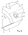
- Figur 2
- einen vergrößerten Ausschnitt aus
Figur 1 Figur 3- eine schematische Darstellung einer Vorrichtung zum Fixieren von zwei Fixierabschnitten aneinander.
- FIG. 1
- a perspective view of a tubular collecting tank to which a holder is attached;
- FIG. 2
- an enlarged section
FIG. 1 and - FIG. 3
- a schematic representation of an apparatus for fixing two fixing portions together.
In
Der Sammelkasten 1 weist des Weiteren einen Deckel 8 auf, der, wie der Boden 3, ebenfalls die Gestalt eines Halbkreiszylindermantels aufweist. Der Boden 3 und der Deckel 8 sind aus Aluminiumblech gebildet und werden miteinander verlötet. An dem Deckel 8 ist ein Halter 10 fixiert, der ebenfalls aus Aluminiumblech gebildet ist. Der Halter 10 weist einen Fuß 12 auf, der im Wesentlichen die Gestalt eines Teilkreiszylinderabschnitts aufweist und einen Fixierabschnitt bildet, der an einem zugehörigen Fixierabschnitt des Deckels 8 anliegt. An den Fixierabschnitten wird der Halter 10 vor dem Verlöten an dem Sammelkasten 1 fixiert.The
Von dem Fuß 12 des Halters 10 erstreckt sich ein Verbindungssteg 14 in radialer Richtung, von dem eine Befestigungslasche 15 mit einem Durchgangsloch 16 ausgeht. Das Durchgangsloch 16 dient zum Durchführen von einem Befestigungsmittel, wie einer Schraube, mit deren Hilfe der Sammelkasten 1 an einer Tragstruktur eines Kraftfahrzeugs befestigbar ist.From the
Um den Halter 10 vor dem Verlöten des Fußes 12 mit dem Deckel 8 an dem Deckel 8 zu fixieren, ist der Fuß 12 an zwei Befestigungsstellen 21, 22 mit dem Deckel 8 verstemmt.To fix the
In
In
Auf der Auflagefläche 33 des Tischs 32, der auch als Matrize oder Gegenhalter bezeichnet wird, liegen zwei Aluminiumbleche 50, 51 übereinander. Das untere Aluminiumblech 50 ist mit einem Durchgangsloch 54 ausgestattet, das einen kreisförmigen Querschnitt aufweist. Das Durchgangsloch 54 ist koaxial zu der Längsachse 35 der Antriebsstange 35 und des Stempels 42 angeordnet. Das Aluminiumblech 50 weist eine Dicke von 3 mm auf. Das Aluminiumblech 51 weist eine Dicke von 1,2 mm auf. Gemäß einem vorteilhaften Aspekt der vorliegenden Erfindung ist das unten angeordnete Aluminiumblech 50 dicker als das oben liegende Aluminiumblech 51. Gemäß einem weiteren Aspekt weist der Stempel 42 einen größeren Durchmesser als das Durchgangsloch 54 auf. Das Verhältnis zwischen dem Durchmesser des Durchgangslochs 54 und dem Durchmesser des Stempels 42 beträgt 0,73. Die beiden Aluminiumbleche 50 und 51 werden verstemmt, indem das dünnere Aluminiumblech 50 in das Durchgangsloch 54 in dem dickeren Aluminiumblech gefügt beziehungsweise verformt wird. Das Verstemmen erfolgt nur durch die von dem Stempel 42 aufgebrachte Druckkraft. Ein Verdrehen des Stempels 42 ist nicht erforderlich.On the
Das Durchgangsloch 54 ist an seinem dem oben liegenden Aluminiumblech 51 zugewandten Ende mit einer Fase versehen. Bei dem Aluminiumblech 50 handelt es sich zum Beispiel um den Fuß 12 des Halters 10 (siehe
Bei dem Aluminiumblech 51 handelt es sich zum Beispiel um den Deckel 8 des Sammelkastens 1 (siehe
Claims (5)
- A method for joining the joining sections, which are disposed on top of one another or next to one another, of at least two parts (12, 8), in particular sheet metal parts, relative to one another, the joining sections being deformed by a plunger (42), one of the joining sections being provided with a hole (24; 54), in particular a through hole, into which the other joining section is deformed by way of the plunger (42), characterized in that the other joining section is deformed into the hole (24; 54) by way of the plunger (42) such that both joining sections are partially plastically deformed.
- The method according to claim 1, characterized in that, prior to deforming the joining sections, the hole (24; 54) is provided with a chamfer on the side facing the other joining section.
- A method according to any one of the preceding claims, characterized in that the joining section having the hole (24; 54) has a greater thickness than the other joining section.
- The method according to claim 3, characterized in that the joining section having the hole (24; 54) is approximately two to three times as thick as the other joining section
- A method according to any one of the preceding claims, characterized in that the hole (24; 54) has a circular cross-section.
Priority Applications (2)
| Application Number | Priority Date | Filing Date | Title |
|---|---|---|---|
| DE200550009688 DE502005009688D1 (en) | 2005-11-17 | 2005-11-17 | fixing |
| EP20050025086 EP1787738B1 (en) | 2005-11-17 | 2005-11-17 | Joining method |
Applications Claiming Priority (1)
| Application Number | Priority Date | Filing Date | Title |
|---|---|---|---|
| EP20050025086 EP1787738B1 (en) | 2005-11-17 | 2005-11-17 | Joining method |
Publications (2)
| Publication Number | Publication Date |
|---|---|
| EP1787738A1 EP1787738A1 (en) | 2007-05-23 |
| EP1787738B1 true EP1787738B1 (en) | 2010-06-02 |
Family
ID=35466515
Family Applications (1)
| Application Number | Title | Priority Date | Filing Date |
|---|---|---|---|
| EP20050025086 Expired - Fee Related EP1787738B1 (en) | 2005-11-17 | 2005-11-17 | Joining method |
Country Status (2)
| Country | Link |
|---|---|
| EP (1) | EP1787738B1 (en) |
| DE (1) | DE502005009688D1 (en) |
Families Citing this family (1)
| Publication number | Priority date | Publication date | Assignee | Title |
|---|---|---|---|---|
| FR2935912B1 (en) * | 2008-09-18 | 2015-04-10 | Valeo Systemes Thermiques | METHOD FOR ASSEMBLING AND BRATING TWO PARTS HAVING ASSEMBLY ELEMENTS |
Family Cites Families (8)
| Publication number | Priority date | Publication date | Assignee | Title |
|---|---|---|---|---|
| DE2713893C3 (en) * | 1977-03-29 | 1980-10-30 | Siemens Ag, 1000 Berlin Und 8000 Muenchen | Device for joining two parts |
| ATE33954T1 (en) | 1984-01-30 | 1988-05-15 | Flowdrill Bv | DRILLING TOOL, PARTICULARLY FOR USE IN A HAND DRILLING MACHINE. |
| US4728842A (en) * | 1986-09-29 | 1988-03-01 | Carbet Corporation | Laminated assembly for a dynamoelectric machine and method for manufacturing laminated assemblies having ridges formed on projections which interlock with recesses of adjacent laminations |
| DD277113A1 (en) * | 1988-11-16 | 1990-03-21 | Karl Marx Stadt Haushaltgeraet | METHOD AND DEVICE FOR CONNECTING TWO FLAE-PARTICULAR PARTS |
| DE19929375B4 (en) | 1999-06-25 | 2008-07-24 | Tox Pressotechnik Gmbh & Co. Kg | Method, apparatus and tool unit for clinching |
| DE10315718A1 (en) | 2002-04-04 | 2003-11-13 | Tox Pressotechnik Gmbh | Deep-draw joining process uses deep-drawing tool to from rivet-like joint with increased strength and quality |
| DE10309381A1 (en) * | 2003-03-03 | 2004-09-16 | Mds Maschinen- Und Werkzeugbau Gmbh | Connecting workpieces within an adding range, by pushing a portion of one workpiece through a stamp towards the other workpiece such that the connecting pin of that workpiece is inserted into the opening of the other workpiece |
| JP4501408B2 (en) * | 2003-10-30 | 2010-07-14 | アイシン精機株式会社 | Fastening method |
-
2005
- 2005-11-17 EP EP20050025086 patent/EP1787738B1/en not_active Expired - Fee Related
- 2005-11-17 DE DE200550009688 patent/DE502005009688D1/en active Active
Also Published As
| Publication number | Publication date |
|---|---|
| EP1787738A1 (en) | 2007-05-23 |
| DE502005009688D1 (en) | 2010-07-15 |
Similar Documents
| Publication | Publication Date | Title |
|---|---|---|
| DE69532542T2 (en) | Einpressmutter | |
| EP2177776B1 (en) | Assembly composed of an attachment element and a piece of sheet metal and a method for producing such an assembly | |
| DE602005005394T2 (en) | Fastening device for self-piercing rivets with improved die | |
| EP2980426B1 (en) | Assembled component comprising a force fitting element and a sheet metal part | |
| EP2834528B1 (en) | Self-piercing rivet with a pre-perforated flat element, production method and joining method therefor | |
| EP2294350B1 (en) | Heat exchanger | |
| WO2003072407A1 (en) | Wiper arm | |
| DE60106028T2 (en) | CONTROLLED MATERIAL FLOW IN PUNCH NIET PROCESS | |
| EP3371467B1 (en) | Semi-hollow self-piercing rivet for thin sheet metal joints, method for producing said semi-hollow self-piercing rivet, and method for producing a joint | |
| EP2730456B1 (en) | Drive for a seat adjusting device for motor vehicles | |
| DE60105724T2 (en) | DIE MOTHER | |
| DE19810367C1 (en) | Method of production of bore in sandwiched metal sheets | |
| DE4419065A1 (en) | Self=stamping riveting machine for overlapping sheet metal components | |
| DE10303184B3 (en) | Plate production process for plates varying in thickness involves forging metal sheet in tool with punch | |
| DE102009014206B4 (en) | cockpit cross member | |
| EP1787738B1 (en) | Joining method | |
| DE112012000353B4 (en) | rivet connection | |
| EP1705446A1 (en) | Tube for a heat exchanger | |
| WO2005056373A1 (en) | Bodywork component and associated production method | |
| EP1078701B1 (en) | Method of producing a riveted joint | |
| DE102006030493B4 (en) | Compressor crankshaft, in particular refrigerant compressor crankshaft, and method for its production | |
| WO2002083357A1 (en) | Method of applying a functional element to a structural component and corresponding tool | |
| DE60319220T2 (en) | ONE-PIECE FLAG NUT | |
| DE102016200357A1 (en) | Method for joining at least two components by means of a hardened joining element | |
| WO2002081145A2 (en) | Method for attaching a functional element to a component and tool associated therewith |
Legal Events
| Date | Code | Title | Description |
|---|---|---|---|
| PUAI | Public reference made under article 153(3) epc to a published international application that has entered the european phase |
Free format text: ORIGINAL CODE: 0009012 |
|
| AK | Designated contracting states |
Kind code of ref document: A1 Designated state(s): AT BE BG CH CY CZ DE DK EE ES FI FR GB GR HU IE IS IT LI LT LU LV MC NL PL PT RO SE SI SK TR |
|
| AX | Request for extension of the european patent |
Extension state: AL BA HR MK YU |
|
| 17P | Request for examination filed |
Effective date: 20071123 |
|
| 17Q | First examination report despatched |
Effective date: 20071220 |
|
| AKX | Designation fees paid |
Designated state(s): DE ES FR GB IT |
|
| GRAP | Despatch of communication of intention to grant a patent |
Free format text: ORIGINAL CODE: EPIDOSNIGR1 |
|
| RTI1 | Title (correction) |
Free format text: JOINING METHOD |
|
| GRAS | Grant fee paid |
Free format text: ORIGINAL CODE: EPIDOSNIGR3 |
|
| GRAA | (expected) grant |
Free format text: ORIGINAL CODE: 0009210 |
|
| AK | Designated contracting states |
Kind code of ref document: B1 Designated state(s): DE ES FR GB IT |
|
| REG | Reference to a national code |
Ref country code: GB Ref legal event code: FG4D Free format text: NOT ENGLISH |
|
| REF | Corresponds to: |
Ref document number: 502005009688 Country of ref document: DE Date of ref document: 20100715 Kind code of ref document: P |
|
| PGFP | Annual fee paid to national office [announced via postgrant information from national office to epo] |
Ref country code: GB Payment date: 20101213 Year of fee payment: 6 Ref country code: IT Payment date: 20101120 Year of fee payment: 6 |
|
| PLBE | No opposition filed within time limit |
Free format text: ORIGINAL CODE: 0009261 |
|
| STAA | Information on the status of an ep patent application or granted ep patent |
Free format text: STATUS: NO OPPOSITION FILED WITHIN TIME LIMIT |
|
| 26N | No opposition filed |
Effective date: 20110303 |
|
| REG | Reference to a national code |
Ref country code: DE Ref legal event code: R097 Ref document number: 502005009688 Country of ref document: DE Effective date: 20110302 |
|
| PGFP | Annual fee paid to national office [announced via postgrant information from national office to epo] |
Ref country code: FR Payment date: 20111130 Year of fee payment: 7 |
|
| GBPC | Gb: european patent ceased through non-payment of renewal fee |
Effective date: 20111117 |
|
| PG25 | Lapsed in a contracting state [announced via postgrant information from national office to epo] |
Ref country code: IT Free format text: LAPSE BECAUSE OF NON-PAYMENT OF DUE FEES Effective date: 20111117 |
|
| PG25 | Lapsed in a contracting state [announced via postgrant information from national office to epo] |
Ref country code: GB Free format text: LAPSE BECAUSE OF NON-PAYMENT OF DUE FEES Effective date: 20111117 |
|
| PGFP | Annual fee paid to national office [announced via postgrant information from national office to epo] |
Ref country code: DE Payment date: 20121227 Year of fee payment: 8 |
|
| REG | Reference to a national code |
Ref country code: FR Ref legal event code: ST Effective date: 20130731 |
|
| PG25 | Lapsed in a contracting state [announced via postgrant information from national office to epo] |
Ref country code: ES Free format text: LAPSE BECAUSE OF FAILURE TO SUBMIT A TRANSLATION OF THE DESCRIPTION OR TO PAY THE FEE WITHIN THE PRESCRIBED TIME-LIMIT Effective date: 20100913 |
|
| PG25 | Lapsed in a contracting state [announced via postgrant information from national office to epo] |
Ref country code: FR Free format text: LAPSE BECAUSE OF NON-PAYMENT OF DUE FEES Effective date: 20121130 |
|
| PG25 | Lapsed in a contracting state [announced via postgrant information from national office to epo] |
Ref country code: DE Free format text: LAPSE BECAUSE OF NON-PAYMENT OF DUE FEES Effective date: 20140603 |
|
| REG | Reference to a national code |
Ref country code: DE Ref legal event code: R119 Ref document number: 502005009688 Country of ref document: DE Effective date: 20140603 |