EP1787493B1 - Earpiece for a hearing aid and a hearing aid - Google Patents
Earpiece for a hearing aid and a hearing aid Download PDFInfo
- Publication number
- EP1787493B1 EP1787493B1 EP05777681.7A EP05777681A EP1787493B1 EP 1787493 B1 EP1787493 B1 EP 1787493B1 EP 05777681 A EP05777681 A EP 05777681A EP 1787493 B1 EP1787493 B1 EP 1787493B1
- Authority
- EP
- European Patent Office
- Prior art keywords
- earpiece
- contact element
- hearing aid
- fixture
- users
- Prior art date
- Legal status (The legal status is an assumption and is not a legal conclusion. Google has not performed a legal analysis and makes no representation as to the accuracy of the status listed.)
- Active
Links
- 210000000613 ear canal Anatomy 0.000 claims description 26
- 241000746998 Tragus Species 0.000 claims description 11
- 230000000284 resting effect Effects 0.000 claims description 6
- 210000000883 ear external Anatomy 0.000 claims description 5
- 239000004952 Polyamide Substances 0.000 claims description 4
- 229920002647 polyamide Polymers 0.000 claims description 4
- 229920006324 polyoxymethylene Polymers 0.000 claims description 4
- -1 polytetrafluoroethylene Polymers 0.000 claims description 4
- 239000000463 material Substances 0.000 claims description 3
- 229920000642 polymer Polymers 0.000 claims description 3
- 229930040373 Paraformaldehyde Natural products 0.000 claims description 2
- 229930182556 Polyacetal Natural products 0.000 claims description 2
- 210000003027 ear inner Anatomy 0.000 claims description 2
- 229920001971 elastomer Polymers 0.000 claims description 2
- 239000000806 elastomer Substances 0.000 claims description 2
- BFMKFCLXZSUVPI-UHFFFAOYSA-N ethyl but-3-enoate Chemical compound CCOC(=O)CC=C BFMKFCLXZSUVPI-UHFFFAOYSA-N 0.000 claims description 2
- 229920001296 polysiloxane Polymers 0.000 claims description 2
- 229920001343 polytetrafluoroethylene Polymers 0.000 claims description 2
- 239000004810 polytetrafluoroethylene Substances 0.000 claims description 2
- 229920002635 polyurethane Polymers 0.000 claims description 2
- 239000004814 polyurethane Substances 0.000 claims description 2
- 229920002725 thermoplastic elastomer Polymers 0.000 claims description 2
- 239000012858 resilient material Substances 0.000 description 4
- 210000003454 tympanic membrane Anatomy 0.000 description 4
- 210000005069 ears Anatomy 0.000 description 3
- 230000003993 interaction Effects 0.000 description 3
- 230000014759 maintenance of location Effects 0.000 description 3
- 238000004519 manufacturing process Methods 0.000 description 3
- 230000006978 adaptation Effects 0.000 description 2
- 238000004026 adhesive bonding Methods 0.000 description 2
- 230000007812 deficiency Effects 0.000 description 2
- 210000001699 lower leg Anatomy 0.000 description 2
- 206010011878 Deafness Diseases 0.000 description 1
- 229920002614 Polyether block amide Polymers 0.000 description 1
- 238000004873 anchoring Methods 0.000 description 1
- 239000011324 bead Substances 0.000 description 1
- 238000005452 bending Methods 0.000 description 1
- 230000008878 coupling Effects 0.000 description 1
- 238000010168 coupling process Methods 0.000 description 1
- 238000005859 coupling reaction Methods 0.000 description 1
- 230000001419 dependent effect Effects 0.000 description 1
- 230000000694 effects Effects 0.000 description 1
- 239000000835 fiber Substances 0.000 description 1
- 230000010370 hearing loss Effects 0.000 description 1
- 231100000888 hearing loss Toxicity 0.000 description 1
- 208000016354 hearing loss disease Diseases 0.000 description 1
- 230000005236 sound signal Effects 0.000 description 1
Images


Classifications
-
- H—ELECTRICITY
- H04—ELECTRIC COMMUNICATION TECHNIQUE
- H04R—LOUDSPEAKERS, MICROPHONES, GRAMOPHONE PICK-UPS OR LIKE ACOUSTIC ELECTROMECHANICAL TRANSDUCERS; DEAF-AID SETS; PUBLIC ADDRESS SYSTEMS
- H04R25/00—Deaf-aid sets, i.e. electro-acoustic or electro-mechanical hearing aids; Electric tinnitus maskers providing an auditory perception
- H04R25/65—Housing parts, e.g. shells, tips or moulds, or their manufacture
- H04R25/652—Ear tips; Ear moulds
- H04R25/656—Non-customized, universal ear tips, i.e. ear tips which are not specifically adapted to the size or shape of the ear or ear canal
-
- H—ELECTRICITY
- H04—ELECTRIC COMMUNICATION TECHNIQUE
- H04R—LOUDSPEAKERS, MICROPHONES, GRAMOPHONE PICK-UPS OR LIKE ACOUSTIC ELECTROMECHANICAL TRANSDUCERS; DEAF-AID SETS; PUBLIC ADDRESS SYSTEMS
- H04R2225/00—Details of deaf aids covered by H04R25/00, not provided for in any of its subgroups
- H04R2225/021—Behind the ear [BTE] hearing aids
-
- H—ELECTRICITY
- H04—ELECTRIC COMMUNICATION TECHNIQUE
- H04R—LOUDSPEAKERS, MICROPHONES, GRAMOPHONE PICK-UPS OR LIKE ACOUSTIC ELECTROMECHANICAL TRANSDUCERS; DEAF-AID SETS; PUBLIC ADDRESS SYSTEMS
- H04R2460/00—Details of hearing devices, i.e. of ear- or headphones covered by H04R1/10 or H04R5/033 but not provided for in any of their subgroups, or of hearing aids covered by H04R25/00 but not provided for in any of its subgroups
- H04R2460/11—Aspects relating to vents, e.g. shape, orientation, acoustic properties in ear tips of hearing devices to prevent occlusion
Definitions
- the present invention relates generally to hearing aids.
- the invention further relates to an earpiece for a hearing aid.
- the invention more particularly, relates to behind-the-ear hearing aids.
- Behind-the-ear (BTE) hearing aids generally comprise a housing, a tube and an earpiece.
- the housing accommodates electronics, a microphone and a miniature loudspeaker, which serve to pick up sounds, amplify them and produce an amplified acoustic output signal.
- the tube provides a conduit for conveying the acoustic signal from the housing to the earpiece, and the earpiece couples acoustic energy from the tube into the ear canal.
- the housing is placed behind the external ear, partially concealed.
- the tube, or at least a part of it, is semi-rigid or resilient in order that the tube may also serve the purpose of resting the hearing aid on the external ear of the user.
- the earpiece is adapted, e.g. through resilience or customization, to the users ear, to rest in the meatus of the ear canal.
- EP-A-1448014 provides an earpiece adapted to allow sounds from outside the ear to propagate to the tympanic membrane.
- This earpiece comprises a resilient fiber for abutting a lower part of the concha when the earpiece is inserted in the ear canal.
- US 2003/002700 A1 discloses a hearing aid system including a BTE hearing aid case, a tube for conducting sound, and an ear tip for anchoring the end of the tube within the ear canal of the user.
- the tube is formed in a preformed shape of a material with sufficient rigidity to support the hearing aid in a proper position on the user's ear.
- the ear tip may be one of several different designs which secures an end of the tube in place in the ear canal in a comfortable manner without the need for an expensive custom made ear mould and without complete occlusion of the ear canal.
- One of the ear tip designs is adapted to hook behind the tragus of the user's ear canal (see figures 17-19 ).
- the plug provides a comfortable, partial support for the earpiece and is adapted to direct sounds amplified by the hearing aid towards the users ear canal.
- the support is complemented by the contact element, which rests against another part of the ear.
- the fixture permits adjusting the contact element and thereby permits adapting the hearing aid to different sizes of ears and ear canals, or to different preferences regarding pretension.
- the adjustment facility permits customizing the hearing aid in order that it may accommodate a wide variety of users.
- the contact element may be partially shaped as an ellipse. It may have any other shape adapted for resting against an inside of the users tragus, thereby holding the earpiece in a fixed position when the earpiece is in use, e.g. it may be essentially circular, elliptic or triangular.
- the contact element may be produced in different sizes for different sizes of ears.
- the fixture comprises a number of guideways.
- the number may be between 1 and 50.
- the guideways may be grooves, flutes or protrusions.
- the contact element may comprise a number of guideways adapted for interaction with the guideways on the fixture.
- the number of guideways may be between 1 and 50.
- the guideways may be grooves or protrusions.
- the guideways allow the contact element to be rotated into a selected orientation relative to the earplug, thereby enabling a fitter to select the most comfortable position of resting against an inside of the user's tragus and the ear canal. Furthermore the rotational capability allows for adjusting and fixing the position of the contact element in the ear for a variety of users.
- the fixture comprises resilient means in order to improve user comfort and to enhance the fit.
- the earpiece is adapted for incremental adjustment.
- the incremental adjustment permits adaptation and simple securing of the size, once decided by the fitter or the end user.
- the adjustment may be provided by providing a flexible beam, such as a branch or a rod, with a plurality of grooves and a catch means for selectively engaging one of the grooves.
- a flexible beam such as a branch or a rod
- the beam may comprise a pair of opposing, generally flat faces, wherein the plurality of grooves is positioned on a first one of the faces.
- the flat opposing faces adapt the beam for bending, e.g. into a loop.
- the fixture may comprise catch means to retain an end of the beam.
- the catch means comprises a rib and a resilient strand, the rib being adapted for engaging one of the grooves.
- the beam is provided with a plurality of grooves on both of the faces. This permits looping the beam either way, e.g. for the purpose of using it for a left ear version and a right ear version, e.g. in combination with the retainer being adapted to accept the end of the beam when entered from either one of two sides.
- the beam may be provided with a plurality of grooves on all of the faces, this provides for a better fixation of the beam.
- the grooves may be placed with increments varying between 0.5 mm and 5 mm and preferably between 1.5 mm and 2.5 mm.
- the earpiece comprises a body with an axis and a through axial bore, wherein the flexible beam extends from the body at an angle from the axis within a range of 45 to 90 degrees, and preferably within a range of 55 to 80 degrees from the axis.
- the body may be generally cylindrical.
- the retainer may simply be arranged to accept the beam end when introduced tangentially to the cylindrical body from either one of two sides, the beam being twisted due to the angled extension of the cantilevered base end.
- the fixture is made of a material selected from the group consisting of polyamide, silicone, polyurethane, polytetrafluoroethylene, ethylvinylacetate, polyacetal, thermoplastic elastomer, polymer, elastomer, and polyoxymethylene.
- the earpiece comprises a plug for contacting the wall of the users ear canal, in order to guide the amplified sound signal into the users auditory canal.
- the plug is adapted to support a sound conduit tube, while it is adapted to permit exterior sounds to bypass the plug in order to reach the users inner ear.
- This avoids uncomfortable occlusion effects.
- the sound bypass is further a substantial advantage to users with a mild hearing deficiency, e.g. users with a hearing deficiency in only part of the frequency range, as they may then still directly hear such sounds as they are able to hear unaided.
- the plug may be adapted to fit the ear canal, thereby not allowing external sounds to bypass the plug. This may be an advantage for moderate to high hearing loss.
- the invention in a second aspect, provides a hearing aid according to claim 17.
- figure 1 shows the outer ear.
- the ear canal 10 and tragus 8 are shown.
- the outer portion of the ear canal is relatively soft.
- Figure 1 further shows Helix 1, Fossa of Helix 2, Antihelix 3, Crus Antihelix 4, Concha (cavuum) 5, Antitragus 6, Lobule 7, and Crus helices 9.
- FIGS 2-5 show a hearing aid 12 with an earpiece 11, according to a first embodiment of the invention.
- the hearing aid comprises a behind-the-ear housing 29 and a tube 26 transferring sound from the housing to the earpiece 11.
- the tube 26 has a first bend 27 and a second bend 28.
- the tube 26 is connected at one end with the housing and at the other end with the earpiece 11
- the earpiece generally comprises a peg 15, an earplug 20 and a body 21.
- the cross section of the body may be circular, elliptic, rectangular or any other form allowing sound from the tube to pass through to the earplug.
- the earplug 20 allows sound from the surroundings to pass through to the tympanic membrane by one, two or more apertures 31.
- the body 21, a rim 22, and a number of spokes 23 define the apertures.
- the peg engages the earplug 20 by threading into a through bore of the plug, the peg having a bead 19 for securing the position.
- Figure 5 shows a branch 13 connected with the peg 15, in a first state.
- the branch comprises a beam-like structure protruding generally radially from the peg.
- the branch is flexible in order that it may be formed into a loop, an exterior side of the loop providing support against the users ear when the earpiece is fitted into the ear.
- the peg 15 has a bore 17 that allows sound from the tube to pass through to the earplug.
- the peg 15 further has a branch 13 and a retainer 18 in form of an eyelet.
- the branch 13 has a pointed end 14.
- the branch 13 extends from the peg by a first, cantilevered end, and threads by its other, pointed end into the retainer 18.
- the branch 13 is a beam like structure with two generally flat opposing faces, each provided with a number of transverse grooves 24, placed along the branch 13 at increments 25 of 2 mm.
- the grooves are 1,65 mm wide.
- the length of the branch 13 from the peg to the pointed end is approximately 44 mm.
- the branch 13 is made of a flexible, resilient material such as a polymer, a polyether block amide or a polyamide.
- the retainer 18 is likewise made of a flexible, resilient material such as polyamide, and comprises a strap that defines a tangential hole, adapted to receive an end of the branch 13.
- the branch 13 will be arrested once inserted into the retainer 18 by a rib of the peg engaging one of the grooves, biased by resilience of the strap.
- the branch 13 Once the branch 13 has been fixed in the retainer 18, as shown in Figure 6 , it forms a loop. This is referred to as the second state of the fixture.
- the size of the loop may vary depending on which of the grooves 24 in the branch 13 that interacts with the rib in the retainer 18.
- the branch 13 has no grooves and may be connected to the peg 15 by gluing.
- the branch 13 may be fixed in the retainer before gluing.
- the protruding end of the branch 13 may be cut off, to reach the third state, which is shown in Figure 7 .
- the branch 13 has grooves on both faces in order that it is possible to form a loop either way around. In this way the branch 13 can be used for both a right ear and a left ear. Between the axis 16 and the base portion of the branch 13 there is an angle of approximately 60° so that when the branch 13 is fixed into the retainer 18, the loop will be twisted. In other embodiments of the invention this angle may vary between 45° and 90°.
- the convex side of the loop provides a contact surface 30, which may be in contact with concha 5, tragus 8, and the ear canal 10.
- Figure 8 shows a hearing aid with an earpiece according to the first embodiment of the invention.
- the earpiece is kept in a fixed position due to retention by the exterior of the branch 13, which provides the contact surface 30.
- the interaction between the branch 13, specifically the contact surface 30, and the inside of the tragus 8 and the interaction of the earplug with the ear canal 10, provides the retention of the earpiece.
- the two bends 27, 28 of the tube 26 provides for the earpiece to be kept in a fixed position in the ear.
- Figure 9 shows an earpiece with a tube 26 according to a first embodiment of the invention, in a second state, i.e. a state where the branch forms a loop with a protruding end.
- the branch 13 has one or more retainers 18 for fixation of the pointed end.
- the branch 13 has one or more spokes 32, which are connected to a hub 33.
- the branch 13 assumes an essentially circular shape.
- Part of the convex side of the fixed branch 13 provides a contact surface 30, which is in contact with the inside of tragus 8 or the ear canal 10 or both.
- the branch may be curved narrower along part of its length so that it assumes an essentially elliptic shape, once the pointed end has been fixed.
- the hub 33 has a number of notches 34.
- Figure 11 shows a peg 37 of a second embodiment of the earpiece according to the invention, figure 11 including views of the peg 37 with the tube 26 from two different viewing angles as well as an enlarged view of the peg 37.
- the peg 37 comprises a number of protrusions 35 that match the notches 34 of the hub 33 (ref. figure 10 ).
- the contact element may be rotated relative to the hub to a particular orientation selected for comfort and proper resting of the contact element behind tragus and in the ear canal, and then assembled so as to safely maintain the selected orientation.
- Figure 12 shows three views of a tube 26, an earplug 20 and an earpiece 36 according to the second embodiment of the invention.
- Figure 13 shows three views of a hearing aid with housing 29, tube 26 and earpiece 36 according to the second embodiment of the invention in the use position on the ear.
- FIG 14 shows an earpiece 38 according to a third embodiment of the invention.
- This earpiece 38 comprises a contact element molded in a resilient material so as to have the general appearance of a half-circle.
- the contact element comprises a hub 39 comprising a number of notches 34.
- Figure 15 shows a hearing aid with housing 29, tube 26, earplug 20 and earpiece 38 according to the third embodiment, which may be clicked on a fixture (e.g. the peg 37 shown in Figure 11 ).
- the contact element may be produced in different sizes for different sizes of ears.
- Figure 16 shows an earpiece 40 according to a fourth embodiment of the invention, this earpiece comprising a contact element molded in a resilient material so as to generally resemble a full circle.
- the earpiece 40 comprises hub 41 in a closed shape comprising a number of notches that match the peg 37 (ref. Figure 11 ).
- Figure 17 suggests how the contact element may be mounted on the fixture by pushing the hub 41 and then the earplug 20 onto the peg 37.
- Figure 18 shows three views of a hearing aid with housing 29, tube 26 and an earpiece 40 according to the fourth embodiment of the invention, in the use position on the ear.
Landscapes
- Engineering & Computer Science (AREA)
- Manufacturing & Machinery (AREA)
- Health & Medical Sciences (AREA)
- General Health & Medical Sciences (AREA)
- Neurosurgery (AREA)
- Otolaryngology (AREA)
- Physics & Mathematics (AREA)
- Acoustics & Sound (AREA)
- Signal Processing (AREA)
- Headphones And Earphones (AREA)
Description
- The present invention relates generally to hearing aids. The invention further relates to an earpiece for a hearing aid. The invention, more particularly, relates to behind-the-ear hearing aids.
- Behind-the-ear (BTE) hearing aids generally comprise a housing, a tube and an earpiece. The housing accommodates electronics, a microphone and a miniature loudspeaker, which serve to pick up sounds, amplify them and produce an amplified acoustic output signal. The tube provides a conduit for conveying the acoustic signal from the housing to the earpiece, and the earpiece couples acoustic energy from the tube into the ear canal. In use, the housing is placed behind the external ear, partially concealed. The tube, or at least a part of it, is semi-rigid or resilient in order that the tube may also serve the purpose of resting the hearing aid on the external ear of the user. The earpiece is adapted, e.g. through resilience or customization, to the users ear, to rest in the meatus of the ear canal.
-
EP-A-1448014 provides an earpiece adapted to allow sounds from outside the ear to propagate to the tympanic membrane. This earpiece comprises a resilient fiber for abutting a lower part of the concha when the earpiece is inserted in the ear canal. -
US 2003/002700 A1 discloses a hearing aid system including a BTE hearing aid case, a tube for conducting sound, and an ear tip for anchoring the end of the tube within the ear canal of the user. The tube is formed in a preformed shape of a material with sufficient rigidity to support the hearing aid in a proper position on the user's ear. The ear tip may be one of several different designs which secures an end of the tube in place in the ear canal in a comfortable manner without the need for an expensive custom made ear mould and without complete occlusion of the ear canal. One of the ear tip designs is adapted to hook behind the tragus of the user's ear canal (seefigures 17-19 ). - It is an object of the invention to provide a hearing aid that is easily adapted to different users.
- It is a further object of the invention to provide a hearing aid that is simple in manufacture.
- It is a still further object to provide a hearing aid with excellent and comfortable retention on the user.
- It is yet a further object of the invention to provide a hearing aid that provides a good acoustical coupling to the users ear canal.
- It is another object of the invention to provide a hearing aid that is partially open to permit sounds to reach the users tympanic membrane, alongside feeding amplified sounds to also reach the users tympanic membrane.
- It is still another object of the invention to provide an earpiece for a hearing aid that is simple in manufacture and that is easily adapted to different users and types of hearing aids.
- These and other objects are fulfilled, according to a first aspect of the invention, by the earpiece as defined in
claim 1. - The plug provides a comfortable, partial support for the earpiece and is adapted to direct sounds amplified by the hearing aid towards the users ear canal. The support is complemented by the contact element, which rests against another part of the ear. According to the invention, the fixture permits adjusting the contact element and thereby permits adapting the hearing aid to different sizes of ears and ear canals, or to different preferences regarding pretension. The adjustment facility permits customizing the hearing aid in order that it may accommodate a wide variety of users.
- In an embodiment of the invention, the contact element may be partially shaped as an ellipse. It may have any other shape adapted for resting against an inside of the users tragus, thereby holding the earpiece in a fixed position when the earpiece is in use, e.g. it may be essentially circular, elliptic or triangular. The contact element may be produced in different sizes for different sizes of ears.
- In a further embodiment of the invention, the fixture comprises a number of guideways. The number may be between 1 and 50. The guideways may be grooves, flutes or protrusions. Further the contact element may comprise a number of guideways adapted for interaction with the guideways on the fixture. The number of guideways may be between 1 and 50. The guideways may be grooves or protrusions. The guideways allow the contact element to be rotated into a selected orientation relative to the earplug, thereby enabling a fitter to select the most comfortable position of resting against an inside of the user's tragus and the ear canal. Furthermore the rotational capability allows for adjusting and fixing the position of the contact element in the ear for a variety of users.
- According to an embodiment, the fixture comprises resilient means in order to improve user comfort and to enhance the fit.
- According to a further embodiment, the earpiece is adapted for incremental adjustment. The incremental adjustment permits adaptation and simple securing of the size, once decided by the fitter or the end user.
- The adjustment may be provided by providing a flexible beam, such as a branch or a rod, with a plurality of grooves and a catch means for selectively engaging one of the grooves.
- The beam may comprise a pair of opposing, generally flat faces, wherein the plurality of grooves is positioned on a first one of the faces. The flat opposing faces adapt the beam for bending, e.g. into a loop.
- The fixture may comprise catch means to retain an end of the beam.
- According to an embodiment, the catch means comprises a rib and a resilient strand, the rib being adapted for engaging one of the grooves. This design is simple in manufacturing and it provides easy adaptation and securing.
- According to a further embodiment, the beam is provided with a plurality of grooves on both of the faces. This permits looping the beam either way, e.g. for the purpose of using it for a left ear version and a right ear version, e.g. in combination with the retainer being adapted to accept the end of the beam when entered from either one of two sides. In a further embodiment the beam may be provided with a plurality of grooves on all of the faces, this provides for a better fixation of the beam. The grooves may be placed with increments varying between 0.5 mm and 5 mm and preferably between 1.5 mm and 2.5 mm.
- According to an embodiment, the earpiece comprises a body with an axis and a through axial bore, wherein the flexible beam extends from the body at an angle from the axis within a range of 45 to 90 degrees, and preferably within a range of 55 to 80 degrees from the axis. This permits adapting the earpiece for deep recession into the ear canal as the beam may partially protrude to engage the users concha behind tragus and the ear canal. The body may be generally cylindrical. Provided the beam is flexible, the retainer may simply be arranged to accept the beam end when introduced tangentially to the cylindrical body from either one of two sides, the beam being twisted due to the angled extension of the cantilevered base end.
- According to an embodiment, the fixture is made of a material selected from the group consisting of polyamide, silicone, polyurethane, polytetrafluoroethylene, ethylvinylacetate, polyacetal, thermoplastic elastomer, polymer, elastomer, and polyoxymethylene.
- According to a further embodiment, the earpiece comprises a plug for contacting the wall of the users ear canal, in order to guide the amplified sound signal into the users auditory canal.
- According to still another embodiment, the plug is adapted to support a sound conduit tube, while it is adapted to permit exterior sounds to bypass the plug in order to reach the users inner ear. This avoids uncomfortable occlusion effects. The sound bypass is further a substantial advantage to users with a mild hearing deficiency, e.g. users with a hearing deficiency in only part of the frequency range, as they may then still directly hear such sounds as they are able to hear unaided.
- According to another embodiment the plug may be adapted to fit the ear canal, thereby not allowing external sounds to bypass the plug. This may be an advantage for moderate to high hearing loss.
- The invention, in a second aspect, provides a hearing aid according to
claim 17. - Further embodiments appear from the dependent claims.
- Further objects, embodiments and advantages will appear from the detailed part of the specification.
- The invention will now be described in more detail with reference to the accompanying drawings, where
-
Fig. 1 illustrates the outer ear as seen from the side; -
Fig. 2 shows a hearing aid according to a first embodiment of the invention, in side view; -
Fig. 3 shows a hearing aid according to a first embodiment of the invention, in rear view; -
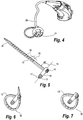
Fig. 4 shows a hearing aid according to a first embodiment of the invention, in perspective; -
Fig. 5 shows a fixture for the earpiece according to a first embodiment of the invention, in a first state; -
Fig. 6 shows a fixture for the earpiece according to a first embodiment of the invention, in a second state; -
Fig. 7 shows a fixture for the earpiece according to a first embodiment of the invention, in a third state; -
Fig. 8 shows a hearing aid according to a first embodiment of the invention, in the use position on the ear; -
Fig. 9 shows a tube with a fixture according to a first embodiment of the invention, the fixture being in a second state; -
Fig. 10 shows a contact element according to a second embodiment of the invention, in a second state; -
Fig. 11 shows part of a hearing aid with a fixture according to a second embodiment of the invention; -
Fig. 12 shows part of a hearing aid with an earpiece according to a second embodiment of the invention; -
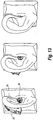
Fig. 13 shows a hearing aid according to the second embodiment of the invention, in the use position on the ear; -
Fig. 14 shows a contact element according to a third embodiment of the invention; -
Fig. 15 shows an exploded view of a hearing aid with an earpiece according to a third embodiment of the invention; -
Fig. 16 shows a contact element according to a fourth embodiment of the invention; -
Fig. 17 shows an exploded view of a hearing aid with an earpiece according to a fourth embodiment of the invention. -
Fig. 18 shows a hearing aid with an earpiece according to the fourth embodiment of the invention, in the use position on the ear. - Reference is first made to
figure 1 , which shows the outer ear. In the figure theear canal 10 andtragus 8 are shown. The outer portion of the ear canal is relatively soft.Figure 1 further showsHelix 1, Fossa ofHelix 2,Antihelix 3,Crus Antihelix 4, Concha (cavuum) 5,Antitragus 6,Lobule 7, andCrus helices 9. - Reference is now made to
Figures 2-5 , which show ahearing aid 12 with anearpiece 11, according to a first embodiment of the invention. The hearing aid comprises a behind-the-ear housing 29 and atube 26 transferring sound from the housing to theearpiece 11. Thetube 26 has afirst bend 27 and asecond bend 28. Thetube 26 is connected at one end with the housing and at the other end with theearpiece 11 - The earpiece generally comprises a
peg 15, anearplug 20 and abody 21. The cross section of the body may be circular, elliptic, rectangular or any other form allowing sound from the tube to pass through to the earplug. Theearplug 20 allows sound from the surroundings to pass through to the tympanic membrane by one, two ormore apertures 31. Thebody 21, arim 22, and a number ofspokes 23 define the apertures. The peg engages theearplug 20 by threading into a through bore of the plug, the peg having abead 19 for securing the position. -
Figure 5 shows abranch 13 connected with thepeg 15, in a first state. The branch comprises a beam-like structure protruding generally radially from the peg. The branch is flexible in order that it may be formed into a loop, an exterior side of the loop providing support against the users ear when the earpiece is fitted into the ear. Thepeg 15 has abore 17 that allows sound from the tube to pass through to the earplug. Thepeg 15 further has abranch 13 and aretainer 18 in form of an eyelet. Thebranch 13 has apointed end 14. Thebranch 13 extends from the peg by a first, cantilevered end, and threads by its other, pointed end into theretainer 18. Thebranch 13 is a beam like structure with two generally flat opposing faces, each provided with a number oftransverse grooves 24, placed along thebranch 13 atincrements 25 of 2 mm. The grooves are 1,65 mm wide. The length of thebranch 13 from the peg to the pointed end is approximately 44 mm. - The
branch 13 is made of a flexible, resilient material such as a polymer, a polyether block amide or a polyamide. Theretainer 18 is likewise made of a flexible, resilient material such as polyamide, and comprises a strap that defines a tangential hole, adapted to receive an end of thebranch 13. Thebranch 13 will be arrested once inserted into theretainer 18 by a rib of the peg engaging one of the grooves, biased by resilience of the strap. Once thebranch 13 has been fixed in theretainer 18, as shown inFigure 6 , it forms a loop. This is referred to as the second state of the fixture. The size of the loop may vary depending on which of thegrooves 24 in thebranch 13 that interacts with the rib in theretainer 18. In this way it is possible to adjust the effective size of the loop to properly fit the users ear. In another embodiment thebranch 13 has no grooves and may be connected to thepeg 15 by gluing. For example, thebranch 13 may be fixed in the retainer before gluing. - The protruding end of the
branch 13 may be cut off, to reach the third state, which is shown inFigure 7 . Thebranch 13 has grooves on both faces in order that it is possible to form a loop either way around. In this way thebranch 13 can be used for both a right ear and a left ear. Between theaxis 16 and the base portion of thebranch 13 there is an angle of approximately 60° so that when thebranch 13 is fixed into theretainer 18, the loop will be twisted. In other embodiments of the invention this angle may vary between 45° and 90°. The convex side of the loop provides acontact surface 30, which may be in contact withconcha 5,tragus 8, and theear canal 10. -
Figure 8 shows a hearing aid with an earpiece according to the first embodiment of the invention. The earpiece is kept in a fixed position due to retention by the exterior of thebranch 13, which provides thecontact surface 30. The interaction between thebranch 13, specifically thecontact surface 30, and the inside of thetragus 8 and the interaction of the earplug with theear canal 10, provides the retention of the earpiece. Also the two bends 27, 28 of thetube 26 provides for the earpiece to be kept in a fixed position in the ear. -
Figure 9 shows an earpiece with atube 26 according to a first embodiment of the invention, in a second state, i.e. a state where the branch forms a loop with a protruding end. - In an
earpiece 36 according to a second embodiment of the invention, shown inFigure 10 , thebranch 13 has one ormore retainers 18 for fixation of the pointed end. Thebranch 13 has one ormore spokes 32, which are connected to ahub 33. Once the pointed end of thebranch 13 has been fixed, thebranch 13 assumes an essentially circular shape. Part of the convex side of the fixedbranch 13 provides acontact surface 30, which is in contact with the inside oftragus 8 or theear canal 10 or both. The branch may be curved narrower along part of its length so that it assumes an essentially elliptic shape, once the pointed end has been fixed. Thehub 33 has a number ofnotches 34. -
Figure 11 shows apeg 37 of a second embodiment of the earpiece according to the invention,figure 11 including views of thepeg 37 with thetube 26 from two different viewing angles as well as an enlarged view of thepeg 37. Thepeg 37 comprises a number ofprotrusions 35 that match thenotches 34 of the hub 33 (ref.figure 10 ). In this way the contact element may be rotated relative to the hub to a particular orientation selected for comfort and proper resting of the contact element behind tragus and in the ear canal, and then assembled so as to safely maintain the selected orientation. -
Figure 12 shows three views of atube 26, anearplug 20 and anearpiece 36 according to the second embodiment of the invention. -
Figure 13 shows three views of a hearing aid withhousing 29,tube 26 andearpiece 36 according to the second embodiment of the invention in the use position on the ear. -
Figure 14 shows anearpiece 38 according to a third embodiment of the invention. Thisearpiece 38 comprises a contact element molded in a resilient material so as to have the general appearance of a half-circle. The contact element comprises ahub 39 comprising a number ofnotches 34. -
Figure 15 shows a hearing aid withhousing 29,tube 26,earplug 20 andearpiece 38 according to the third embodiment, which may be clicked on a fixture (e.g. thepeg 37 shown inFigure 11 ). The contact element may be produced in different sizes for different sizes of ears. -
Figure 16 shows anearpiece 40 according to a fourth embodiment of the invention, this earpiece comprising a contact element molded in a resilient material so as to generally resemble a full circle. Theearpiece 40 compriseshub 41 in a closed shape comprising a number of notches that match the peg 37 (ref.Figure 11 ). -
Figure 17 suggests how the contact element may be mounted on the fixture by pushing thehub 41 and then theearplug 20 onto thepeg 37. -
Figure 18 shows three views of a hearing aid withhousing 29,tube 26 and anearpiece 40 according to the fourth embodiment of the invention, in the use position on the ear.
Claims (19)
- An earpiece (11) for a hearing aid (12), adapted to direct sounds amplified by the hearing aid towards the users ear canal, and comprising- a plug (20) for contacting the meatus of the users ear canal,- a contact element (13) for resting against an inside of the users tragus, and- a fixture (15, 37) for holding the plug and the contact element together, characterized by further comprising- means (18, 24) for adjusting the contact element.
- The earpiece (11) according to claim 1, wherein the contact element (13) is partially shaped as an ellipse.
- The earpiece (11) according to any of the preceding claims, wherein the fixture (15, 37) comprises a number of guideways (35).
- The earpiece (11) according to any of the preceding claims, wherein the contact element (13) comprises a number of guideways (34).
- The earpiece (11) according to claim 1, wherein the means (18, 24) for adjusting the contact element (13) is provided in the fixture (15, 37).
- The earpiece (11) according to claim 5, wherein the fixture (15, 37) comprises resilient means (13, 23, 32) adapted for resiliently spacing the plug (20) from the contact element (13).
- The earpiece (11) according to claim 5, wherein the fixture (15, 37) is adapted for incremental adjustment of the spacing.
- The earpiece (11) according to claim 5, wherein the fixture (15, 37) comprises a flexible beam (13) with a plurality of grooves (24) and a catch means (18) for selectively engaging one of the grooves.
- The earpiece (11) according to claim 8, wherein the beam (13) comprises a pair of opposing, generally flat faces, and wherein the plurality of grooves (24) is positioned on a first one of the faces.
- The earpiece (11) according to claim 9, wherein the beam (13) is adapted for being bent into a loop, and wherein the fixture (15, 37) comprises catch means (18) to retain an end of the beam.
- The earpiece (11) according to claim 10, wherein the catch means (18) comprises a rib and a resilient strand, the rib being adapted for engaging one of the grooves.
- The earpiece (11) according to claim 10, wherein the beam (13) is provided with a plurality of grooves (24) on both of the faces.
- The earpiece (11) according to claim 8, wherein the earpiece comprises a body (21) with an axis and a through axial bore, wherein the flexible beam (13) extends from the body at an angle from the axis within a range of 45 to 90 degrees, and preferably within a range of 55 to 80 degrees from the axis.
- The earpiece (11) according to any of the preceding claims, wherein the fixture (15, 37) is made of a material selected from the group consisting of polyamide, silicone, polyurethane, polytetrafluoroethylene, ethylvinylacetate, polyacetal, TPE, polymer, elastomer, and polyoxymethylene.
- The earpiece (11) according to any of the preceding claims, comprising a plug (20) for contacting an inside of the users ear canal.
- The ear piece according to claim 15, wherein the plug (20) is adapted to support a sound conduit tube (26) and to provide an aperture to permit exterior sounds to reach the users inner ear.
- A hearing aid (12) comprising an earpiece (11), a housing, (29) and a sound conduit tube (26), wherein said earpiece (11) has a plug for contacting the meatus of the users ear canal, a contact element (13) for resting against an inside of the users tragus, and a fixture (15, 37) for holding the plug and the contact element together, characterized by further comprising means (18, 24) for adjusting the contact element.
- The hearing aid (12) according to claim 17, wherein the tube (26) is semi-rigid and adapted to fit over the users external ear in order to support the hearing aid.
- The hearing aid (12) according to claim 18, wherein the tube (26) has a first bend (26) to fit over the users ear and a second bend (27) to direct the tube towards the users ear canal.
Applications Claiming Priority (3)
| Application Number | Priority Date | Filing Date | Title |
|---|---|---|---|
| DKPA200401349 | 2004-09-07 | ||
| US66191705P | 2005-03-16 | 2005-03-16 | |
| PCT/DK2005/000563 WO2006026988A1 (en) | 2004-09-07 | 2005-09-03 | Earpiece for a hearing aid and a hearing aid |
Publications (2)
| Publication Number | Publication Date |
|---|---|
| EP1787493A1 EP1787493A1 (en) | 2007-05-23 |
| EP1787493B1 true EP1787493B1 (en) | 2016-07-06 |
Family
ID=35478249
Family Applications (1)
| Application Number | Title | Priority Date | Filing Date |
|---|---|---|---|
| EP05777681.7A Active EP1787493B1 (en) | 2004-09-07 | 2005-09-03 | Earpiece for a hearing aid and a hearing aid |
Country Status (5)
| Country | Link |
|---|---|
| EP (1) | EP1787493B1 (en) |
| JP (1) | JP4619410B2 (en) |
| AU (1) | AU2005282055B2 (en) |
| CA (1) | CA2579358C (en) |
| WO (1) | WO2006026988A1 (en) |
Families Citing this family (18)
| Publication number | Priority date | Publication date | Assignee | Title |
|---|---|---|---|---|
| EP1829419B1 (en) | 2004-12-22 | 2012-03-07 | Widex A/S | Bte hearing aid with customized shell and earplug |
| DK1911328T3 (en) | 2005-07-08 | 2019-04-08 | Widex As | A HEARING AND A EARRING FOR A HEARING |
| EP1811808B1 (en) | 2006-01-19 | 2017-03-22 | Oticon A/S | Ear canal device retention means |
| US7899200B2 (en) | 2006-06-02 | 2011-03-01 | Phonak Ag | Universal-fit hearing device |
| WO2007028659A1 (en) * | 2006-06-02 | 2007-03-15 | Phonak Ag | Universal-fit hearing device |
| US7931027B2 (en) | 2007-10-15 | 2011-04-26 | Widex A/S | Earplug with engagement means |
| US8885858B2 (en) | 2007-12-27 | 2014-11-11 | Gn Resound A/S | Modular hearing instrument |
| JP6144865B2 (en) * | 2007-12-27 | 2017-06-07 | ジーエヌ リザウンド エー/エスGn Resound A/S | Hearing assistance device having a wall formed of a printed circuit board |
| KR20110065518A (en) * | 2008-10-10 | 2011-06-15 | 비덱스 에이/에스 | A retaining module for the earpiece of a hearing aid |
| EP2433436B1 (en) | 2009-05-18 | 2019-07-10 | Sonova AG | Bendable hearing device |
| GB0922610D0 (en) * | 2009-12-23 | 2010-02-10 | B & W Group Ltd | Earphone |
| JP5522022B2 (en) * | 2010-12-24 | 2014-06-18 | パナソニック株式会社 | hearing aid |
| JP4993023B1 (en) * | 2011-02-25 | 2012-08-08 | パナソニック株式会社 | hearing aid |
| EP2816822B1 (en) | 2013-06-20 | 2016-05-04 | Oticon A/s | Ear strap for a probe tube |
| KR20170080575A (en) | 2014-10-30 | 2017-07-10 | 소니 주식회사 | Sound output device and sound guide device |
| EP3425922B1 (en) * | 2016-03-01 | 2021-02-17 | Sony Corporation | Sound output device |
| EP3352479A1 (en) * | 2017-09-05 | 2018-07-25 | Oticon A/s | Hearing aid with flexible insertion member |
| US11863928B2 (en) * | 2020-11-12 | 2024-01-02 | Gn Hearing A/S | Retaining member for earpiece of hearing device |
Family Cites Families (15)
| Publication number | Priority date | Publication date | Assignee | Title |
|---|---|---|---|---|
| US3934100A (en) * | 1974-04-22 | 1976-01-20 | Seeburg Corporation | Acoustic coupler for use with auditory equipment |
| US3915166A (en) * | 1974-04-23 | 1975-10-28 | Frank P Mccrink | Earplug attached to an elastic band |
| JPS58104077U (en) * | 1981-12-30 | 1983-07-15 | ソニー株式会社 | electroacoustic transducer |
| JPH0542474Y2 (en) * | 1989-08-17 | 1993-10-26 | ||
| JP2511124Y2 (en) * | 1992-03-27 | 1996-09-18 | リオン株式会社 | Ear-hook type hearing aid holder |
| JP3834846B2 (en) * | 1995-08-23 | 2006-10-18 | ソニー株式会社 | Electroacoustic transducer |
| US5794461A (en) * | 1995-10-13 | 1998-08-18 | The Mckinley Group | Key operable restraining device |
| US5761298A (en) * | 1996-05-31 | 1998-06-02 | Plantronics, Inc. | Communications headset with universally adaptable receiver and voice transmitter |
| CA2295750A1 (en) * | 1997-07-18 | 1999-01-28 | Resound Corporation | Behind the ear hearing aid system |
| JP2000092581A (en) * | 1998-09-08 | 2000-03-31 | Yoshihisa Shigyo | Inner ear headphone device |
| JP3897920B2 (en) * | 1998-11-26 | 2007-03-28 | Necトーキン株式会社 | Bone conduction voice detector |
| WO2001028289A1 (en) * | 1999-10-14 | 2001-04-19 | Erich Bayer | Otoplastic for behind-the-ear hearing aids |
| JP2001333484A (en) * | 2000-05-24 | 2001-11-30 | Yoshitaka Watanabe | Earphone |
| US20020096391A1 (en) * | 2001-01-24 | 2002-07-25 | Smith Richard C. | Flexible ear insert and audio communication link |
| ATE308221T1 (en) * | 2003-02-14 | 2005-11-15 | Gn Resound As | HOLDING ELEMENT FOR EARPIECE |
-
2005
- 2005-09-03 JP JP2007529316A patent/JP4619410B2/en not_active Expired - Fee Related
- 2005-09-03 CA CA2579358A patent/CA2579358C/en not_active Expired - Fee Related
- 2005-09-03 EP EP05777681.7A patent/EP1787493B1/en active Active
- 2005-09-03 WO PCT/DK2005/000563 patent/WO2006026988A1/en active Application Filing
- 2005-09-03 AU AU2005282055A patent/AU2005282055B2/en not_active Ceased
Also Published As
| Publication number | Publication date |
|---|---|
| CA2579358C (en) | 2011-11-15 |
| AU2005282055A1 (en) | 2006-03-16 |
| CA2579358A1 (en) | 2006-03-16 |
| AU2005282055B2 (en) | 2008-12-04 |
| JP4619410B2 (en) | 2011-01-26 |
| WO2006026988A1 (en) | 2006-03-16 |
| JP2008512882A (en) | 2008-04-24 |
| EP1787493A1 (en) | 2007-05-23 |
Similar Documents
| Publication | Publication Date | Title |
|---|---|---|
| US7720244B2 (en) | Earpiece for a hearing aid and a hearing aid | |
| EP1787493B1 (en) | Earpiece for a hearing aid and a hearing aid | |
| EP0997057B1 (en) | Behind the ear hearing aid system | |
| US8873786B2 (en) | Retaining module for the earpiece of a hearing aid | |
| US7590255B2 (en) | Retaining member for an earpiece | |
| EP2449797B1 (en) | Hearing device with a vent extension | |
| EP1800516B1 (en) | A bte hearing aid adaptor | |
| US20080025541A1 (en) | Behind-the-ear type hearing aid | |
| US7082207B2 (en) | Adjustable behind-the-ear communication device | |
| US20120257774A1 (en) | Ear plug for a hearing aid and a hearing aid | |
| JP2009500926A (en) | Hearing aids and earpieces for hearing aids | |
| US20140056456A1 (en) | Bte hearing aid with an elongated securing member | |
| CN101023707B (en) | Earpiece for a hearing aid and a hearing aid | |
| EP1763284B1 (en) | Behind the ear hearing system | |
| JP5308518B2 (en) | Elastic shell for inner ear receiver | |
| JP5308518B6 (en) | Elastic shell for inner ear receiver | |
| WO2005043951A1 (en) | Ergonomic ear piece |
Legal Events
| Date | Code | Title | Description |
|---|---|---|---|
| PUAI | Public reference made under article 153(3) epc to a published international application that has entered the european phase |
Free format text: ORIGINAL CODE: 0009012 |
|
| 17P | Request for examination filed |
Effective date: 20070305 |
|
| AK | Designated contracting states |
Kind code of ref document: A1 Designated state(s): AT BE BG CH CY CZ DE DK EE ES FI FR GB GR HU IE IS IT LI LT LU LV MC NL PL PT RO SE SI SK TR |
|
| DAX | Request for extension of the european patent (deleted) | ||
| 17Q | First examination report despatched |
Effective date: 20110324 |
|
| RAP1 | Party data changed (applicant data changed or rights of an application transferred) |
Owner name: WIDEX A/S |
|
| GRAP | Despatch of communication of intention to grant a patent |
Free format text: ORIGINAL CODE: EPIDOSNIGR1 |
|
| INTG | Intention to grant announced |
Effective date: 20160406 |
|
| GRAS | Grant fee paid |
Free format text: ORIGINAL CODE: EPIDOSNIGR3 |
|
| GRAA | (expected) grant |
Free format text: ORIGINAL CODE: 0009210 |
|
| AK | Designated contracting states |
Kind code of ref document: B1 Designated state(s): AT BE BG CH CY CZ DE DK EE ES FI FR GB GR HU IE IS IT LI LT LU LV MC NL PL PT RO SE SI SK TR |
|
| REG | Reference to a national code |
Ref country code: GB Ref legal event code: FG4D |
|
| REG | Reference to a national code |
Ref country code: AT Ref legal event code: REF Ref document number: 811438 Country of ref document: AT Kind code of ref document: T Effective date: 20160715 Ref country code: CH Ref legal event code: EP |
|
| REG | Reference to a national code |
Ref country code: IE Ref legal event code: FG4D |
|
| REG | Reference to a national code |
Ref country code: DK Ref legal event code: T3 Effective date: 20160801 |
|
| REG | Reference to a national code |
Ref country code: DE Ref legal event code: R096 Ref document number: 602005049687 Country of ref document: DE |
|
| REG | Reference to a national code |
Ref country code: NL Ref legal event code: MP Effective date: 20160706 |
|
| REG | Reference to a national code |
Ref country code: LT Ref legal event code: MG4D |
|
| REG | Reference to a national code |
Ref country code: AT Ref legal event code: MK05 Ref document number: 811438 Country of ref document: AT Kind code of ref document: T Effective date: 20160706 |
|
| PG25 | Lapsed in a contracting state [announced via postgrant information from national office to epo] |
Ref country code: IS Free format text: LAPSE BECAUSE OF FAILURE TO SUBMIT A TRANSLATION OF THE DESCRIPTION OR TO PAY THE FEE WITHIN THE PRESCRIBED TIME-LIMIT Effective date: 20161106 Ref country code: IT Free format text: LAPSE BECAUSE OF FAILURE TO SUBMIT A TRANSLATION OF THE DESCRIPTION OR TO PAY THE FEE WITHIN THE PRESCRIBED TIME-LIMIT Effective date: 20160706 Ref country code: LT Free format text: LAPSE BECAUSE OF FAILURE TO SUBMIT A TRANSLATION OF THE DESCRIPTION OR TO PAY THE FEE WITHIN THE PRESCRIBED TIME-LIMIT Effective date: 20160706 Ref country code: FI Free format text: LAPSE BECAUSE OF FAILURE TO SUBMIT A TRANSLATION OF THE DESCRIPTION OR TO PAY THE FEE WITHIN THE PRESCRIBED TIME-LIMIT Effective date: 20160706 Ref country code: NL Free format text: LAPSE BECAUSE OF FAILURE TO SUBMIT A TRANSLATION OF THE DESCRIPTION OR TO PAY THE FEE WITHIN THE PRESCRIBED TIME-LIMIT Effective date: 20160706 |
|
| PG25 | Lapsed in a contracting state [announced via postgrant information from national office to epo] |
Ref country code: LV Free format text: LAPSE BECAUSE OF FAILURE TO SUBMIT A TRANSLATION OF THE DESCRIPTION OR TO PAY THE FEE WITHIN THE PRESCRIBED TIME-LIMIT Effective date: 20160706 Ref country code: BE Free format text: LAPSE BECAUSE OF NON-PAYMENT OF DUE FEES Effective date: 20160706 Ref country code: GR Free format text: LAPSE BECAUSE OF FAILURE TO SUBMIT A TRANSLATION OF THE DESCRIPTION OR TO PAY THE FEE WITHIN THE PRESCRIBED TIME-LIMIT Effective date: 20161007 Ref country code: ES Free format text: LAPSE BECAUSE OF FAILURE TO SUBMIT A TRANSLATION OF THE DESCRIPTION OR TO PAY THE FEE WITHIN THE PRESCRIBED TIME-LIMIT Effective date: 20160706 Ref country code: SE Free format text: LAPSE BECAUSE OF FAILURE TO SUBMIT A TRANSLATION OF THE DESCRIPTION OR TO PAY THE FEE WITHIN THE PRESCRIBED TIME-LIMIT Effective date: 20160706 Ref country code: PT Free format text: LAPSE BECAUSE OF FAILURE TO SUBMIT A TRANSLATION OF THE DESCRIPTION OR TO PAY THE FEE WITHIN THE PRESCRIBED TIME-LIMIT Effective date: 20161107 Ref country code: PL Free format text: LAPSE BECAUSE OF FAILURE TO SUBMIT A TRANSLATION OF THE DESCRIPTION OR TO PAY THE FEE WITHIN THE PRESCRIBED TIME-LIMIT Effective date: 20160706 Ref country code: AT Free format text: LAPSE BECAUSE OF FAILURE TO SUBMIT A TRANSLATION OF THE DESCRIPTION OR TO PAY THE FEE WITHIN THE PRESCRIBED TIME-LIMIT Effective date: 20160706 |
|
| REG | Reference to a national code |
Ref country code: DE Ref legal event code: R097 Ref document number: 602005049687 Country of ref document: DE |
|
| PG25 | Lapsed in a contracting state [announced via postgrant information from national office to epo] |
Ref country code: RO Free format text: LAPSE BECAUSE OF FAILURE TO SUBMIT A TRANSLATION OF THE DESCRIPTION OR TO PAY THE FEE WITHIN THE PRESCRIBED TIME-LIMIT Effective date: 20160706 Ref country code: MC Free format text: LAPSE BECAUSE OF FAILURE TO SUBMIT A TRANSLATION OF THE DESCRIPTION OR TO PAY THE FEE WITHIN THE PRESCRIBED TIME-LIMIT Effective date: 20160706 Ref country code: EE Free format text: LAPSE BECAUSE OF FAILURE TO SUBMIT A TRANSLATION OF THE DESCRIPTION OR TO PAY THE FEE WITHIN THE PRESCRIBED TIME-LIMIT Effective date: 20160706 |
|
| PLBE | No opposition filed within time limit |
Free format text: ORIGINAL CODE: 0009261 |
|
| STAA | Information on the status of an ep patent application or granted ep patent |
Free format text: STATUS: NO OPPOSITION FILED WITHIN TIME LIMIT |
|
| PG25 | Lapsed in a contracting state [announced via postgrant information from national office to epo] |
Ref country code: SK Free format text: LAPSE BECAUSE OF FAILURE TO SUBMIT A TRANSLATION OF THE DESCRIPTION OR TO PAY THE FEE WITHIN THE PRESCRIBED TIME-LIMIT Effective date: 20160706 Ref country code: BG Free format text: LAPSE BECAUSE OF FAILURE TO SUBMIT A TRANSLATION OF THE DESCRIPTION OR TO PAY THE FEE WITHIN THE PRESCRIBED TIME-LIMIT Effective date: 20161006 Ref country code: CZ Free format text: LAPSE BECAUSE OF FAILURE TO SUBMIT A TRANSLATION OF THE DESCRIPTION OR TO PAY THE FEE WITHIN THE PRESCRIBED TIME-LIMIT Effective date: 20160706 |
|
| 26N | No opposition filed |
Effective date: 20170407 |
|
| GBPC | Gb: european patent ceased through non-payment of renewal fee |
Effective date: 20161006 |
|
| REG | Reference to a national code |
Ref country code: IE Ref legal event code: MM4A |
|
| REG | Reference to a national code |
Ref country code: FR Ref legal event code: ST Effective date: 20170531 |
|
| PG25 | Lapsed in a contracting state [announced via postgrant information from national office to epo] |
Ref country code: FR Free format text: LAPSE BECAUSE OF NON-PAYMENT OF DUE FEES Effective date: 20160930 Ref country code: GB Free format text: LAPSE BECAUSE OF NON-PAYMENT OF DUE FEES Effective date: 20161006 Ref country code: IE Free format text: LAPSE BECAUSE OF NON-PAYMENT OF DUE FEES Effective date: 20160903 |
|
| PG25 | Lapsed in a contracting state [announced via postgrant information from national office to epo] |
Ref country code: SI Free format text: LAPSE BECAUSE OF FAILURE TO SUBMIT A TRANSLATION OF THE DESCRIPTION OR TO PAY THE FEE WITHIN THE PRESCRIBED TIME-LIMIT Effective date: 20160706 Ref country code: LU Free format text: LAPSE BECAUSE OF NON-PAYMENT OF DUE FEES Effective date: 20160903 |
|
| PG25 | Lapsed in a contracting state [announced via postgrant information from national office to epo] |
Ref country code: CY Free format text: LAPSE BECAUSE OF FAILURE TO SUBMIT A TRANSLATION OF THE DESCRIPTION OR TO PAY THE FEE WITHIN THE PRESCRIBED TIME-LIMIT Effective date: 20160706 Ref country code: HU Free format text: LAPSE BECAUSE OF FAILURE TO SUBMIT A TRANSLATION OF THE DESCRIPTION OR TO PAY THE FEE WITHIN THE PRESCRIBED TIME-LIMIT; INVALID AB INITIO Effective date: 20050903 |
|
| PG25 | Lapsed in a contracting state [announced via postgrant information from national office to epo] |
Ref country code: TR Free format text: LAPSE BECAUSE OF FAILURE TO SUBMIT A TRANSLATION OF THE DESCRIPTION OR TO PAY THE FEE WITHIN THE PRESCRIBED TIME-LIMIT Effective date: 20160706 |
|
| PGFP | Annual fee paid to national office [announced via postgrant information from national office to epo] |
Ref country code: CH Payment date: 20221001 Year of fee payment: 18 |
|
| PGFP | Annual fee paid to national office [announced via postgrant information from national office to epo] |
Ref country code: DK Payment date: 20230822 Year of fee payment: 19 Ref country code: DE Payment date: 20230822 Year of fee payment: 19 |