EP1786646B2 - Method for train formation from individual cars - Google Patents
Method for train formation from individual cars Download PDFInfo
- Publication number
- EP1786646B2 EP1786646B2 EP05777180.0A EP05777180A EP1786646B2 EP 1786646 B2 EP1786646 B2 EP 1786646B2 EP 05777180 A EP05777180 A EP 05777180A EP 1786646 B2 EP1786646 B2 EP 1786646B2
- Authority
- EP
- European Patent Office
- Prior art keywords
- wagon
- supply
- train
- information
- unit
- Prior art date
- Legal status (The legal status is an assumption and is not a legal conclusion. Google has not performed a legal analysis and makes no representation as to the accuracy of the status listed.)
- Active
Links
- 238000000034 method Methods 0.000 title claims description 22
- 230000015572 biosynthetic process Effects 0.000 title claims description 14
- 230000003137 locomotive effect Effects 0.000 claims description 17
- 230000008878 coupling Effects 0.000 description 10
- 238000010168 coupling process Methods 0.000 description 10
- 238000005859 coupling reaction Methods 0.000 description 10
- 230000008901 benefit Effects 0.000 description 8
- 238000009434 installation Methods 0.000 description 7
- 238000004519 manufacturing process Methods 0.000 description 6
- 230000005540 biological transmission Effects 0.000 description 4
- 239000000872 buffer Substances 0.000 description 4
- 230000009467 reduction Effects 0.000 description 4
- 230000007704 transition Effects 0.000 description 3
- 230000000712 assembly Effects 0.000 description 2
- 238000000429 assembly Methods 0.000 description 2
- 239000002131 composite material Substances 0.000 description 2
- 238000004378 air conditioning Methods 0.000 description 1
- 239000011324 bead Substances 0.000 description 1
- 230000001419 dependent effect Effects 0.000 description 1
- 238000003745 diagnosis Methods 0.000 description 1
- 230000000694 effects Effects 0.000 description 1
- 230000010365 information processing Effects 0.000 description 1
- 238000012423 maintenance Methods 0.000 description 1
- 230000000717 retained effect Effects 0.000 description 1
- 238000009423 ventilation Methods 0.000 description 1
Images

Classifications
-
- B—PERFORMING OPERATIONS; TRANSPORTING
- B61—RAILWAYS
- B61C—LOCOMOTIVES; MOTOR RAILCARS
- B61C3/00—Electric locomotives or railcars
-
- B—PERFORMING OPERATIONS; TRANSPORTING
- B61—RAILWAYS
- B61D—BODY DETAILS OR KINDS OF RAILWAY VEHICLES
- B61D1/00—Carriages for ordinary railway passenger traffic
-
- B—PERFORMING OPERATIONS; TRANSPORTING
- B60—VEHICLES IN GENERAL
- B60L—PROPULSION OF ELECTRICALLY-PROPELLED VEHICLES; SUPPLYING ELECTRIC POWER FOR AUXILIARY EQUIPMENT OF ELECTRICALLY-PROPELLED VEHICLES; ELECTRODYNAMIC BRAKE SYSTEMS FOR VEHICLES IN GENERAL; MAGNETIC SUSPENSION OR LEVITATION FOR VEHICLES; MONITORING OPERATING VARIABLES OF ELECTRICALLY-PROPELLED VEHICLES; ELECTRIC SAFETY DEVICES FOR ELECTRICALLY-PROPELLED VEHICLES
- B60L2200/00—Type of vehicles
- B60L2200/26—Rail vehicles
Definitions
- the present invention relates to a method for forming a train from individual wagons without traction equipment, in particular from passenger train wagons, in which at least one traction unit is coupled to at least one autonomously operable first individual wagon to form a train combination. It also relates to a tensile assembly that can be formed using this method according to the invention. Finally, it relates to a single car without traction equipment for a train assembly according to the invention.
- Such single wagons without traction equipment are mostly passenger wagons, i. H. Wagons that carry travelers without having their own drive. Unlike the so-called articulated train wagons for articulated trains, these single wagons have running gears at both ends so that they can be maneuvered individually. They are usually coupled with locomotives or the like, which provide the traction for the train set. The locomotive usually supplies the individual cars coupled to it with the energy required to supply the on-board systems such as lighting, air conditioning, ventilation, information systems, etc. This is done via a high-voltage line that runs through the train set, the so-called train bus bar (e.g. 1000 V to 3000 V, DC or AC voltage).
- train bus bar e.g. 1000 V to 3000 V, DC or AC voltage
- the locomotive also supplies the individual wagons coupled to it with control information and, if necessary, additional information.
- This is done via an information line running through the train network, often a so-called train bus (e.g. WTB, wired train bus according to UIC 556: "information transmission in the train - train bus").
- train bus e.g. WTB, wired train bus according to UIC 556: "information transmission in the train - train bus”
- information can be transmitted, for example, via conventional lines, e.g.
- the information can also be transmitted via other media, e.g. for the compressed air brake through pneumatic lines or hydraulic lines.
- Such passenger coaches today consist of a car body of about 20 to 28 m in length. Buffers and draw hooks, less often automatic couplings, are attached to the ends.
- the wagons are single-deck or double-deck.
- passenger coaches are generally designed in accordance with the requirements of the UIC in order to ensure universal interchangeability and thus international use of the coaches through standardized mechanical interfaces (buffers, couplings, brakes, transition) and standardized electrical interfaces (power supply, control lines, information lines). .
- Essential parts of the wagons are specified in UIC 567: "General provisions for passenger coaches".
- Specific energy supply issues are specified in UIC 550: "Electrical energy supply systems for passenger train wagons" and UIC 552: “Electrical energy supply for trains - Technical characteristics of the train busbar (ZS)".
- the known passenger carriages are usually designed as autonomously operable carriages, d. H. each car can be operated on its own coupled to a corresponding traction unit. It can be coupled with any other wagon via UIC-compliant interfaces. All devices required for operation are present in each car and designed to supply this one car. This allows trains of different lengths to be formed from a wide variety of cars.
- a further disadvantage occurs when the required assemblies, for example in the case of wagons not designed as high-floor wagons, cannot be arranged, or not completely, below the wagon floor or in the roof space.
- the required assemblies for example in the case of wagons not designed as high-floor wagons, cannot be arranged, or not completely, below the wagon floor or in the roof space.
- at least some of the necessary units then have to be accommodated in cupboards in the passenger compartment, which reduces the transport capacity of the wagon due to the space required for this.
- This principle has the advantage of lighter, less complex and therefore cheaper cars.
- it has the disadvantage of less flexibility in train formation.
- trains with car numbers can be formed that are a multiple correspond to the number of cars in the basic units.
- a generic freight train with a supply car which takes over the energy supply of another freight car that cannot be operated autonomously, is from the U.S. 6,087,739 known.
- the present invention is therefore based on the object of providing a method for train formation, a train set and individual wagons of the type mentioned at the outset, which does not have the above-mentioned disadvantages or at least has them to a lesser extent and, in particular, is as flexible as possible while being simple and inexpensive to implement ensure train formation.
- the present invention solves this problem based on a method for train formation according to the preamble of claim 1 by the features specified in the characterizing part of claim 1. It also solves this problem based on a train assembly according to the preamble of claim 9 by the features specified in the characterizing part of claim 9 . Finally, it solves this problem with individual wagons having the features of claims 21 and 22 and with a wagon unit having the features of claim 23.
- the present invention is based on the technical teaching that flexible train formation from individual wagons without traction equipment is made possible with simple and cost-effective manufacturability if a supply wagon is used as the first individual wagon, which to take over essentially the entire energy supply and information supply of at least one non-autonomously operable second individual car is formed in normal operation.
- Electrical energy is predominantly used today to supply the cars with energy.
- Other forms of energy are, for example, pneumatic energy, which is used, for example, for the brake supply and/or the air spring and other drives. This is transmitted via the one continuous air line, the so-called main air reservoir line. Hydraulic energy can also be provided and used in the train set.
- Information used in the train set is, for example, information about the status of the train, for controlling the train set and individual systems arranged in it, diagnostics or information for the passengers and/or the train crew. These are usually transmitted electrically via conventional control lines, for example via relays, or via digital bus systems. For pneumatically controlled braking systems or electropneumatically controlled braking systems, braking information is transmitted via a compressed air line, the so-called main air line.
- the supply car is designed such that during normal operation it essentially takes over the entire energy supply and/or essentially the entire information supply of at least one second individual car that cannot be operated autonomously, which is also referred to here as a supplementary car.
- the respective second individual wagon can have corresponding emergency supply devices for emergency operation, which may be brief, for safety reasons.
- supplementary wagons can also contain individual systems that implement subtasks in the supplementary wagon independently of the supply wagon.
- the energy supply can only be arranged in the supply wagons in order to also supply the supplementary wagons, but the brake control can be arranged in each wagon of the train set, including the supplementary wagon.
- the supply wagon according to the invention can be coupled with one or more second individual wagons for whose supply it is designed to form a first wagon unit, which has a number of advantages over a coupled unit made up of the same number of known autonomously operable individual wagons.
- the energy supply device of the supply car which is equipped with higher power to supply the cars of the first car unit, can be designed so that its mass is significantly lower than the total mass of the known individual energy supply devices of the individual cars. This reduction in mass is not only noticeable in the manufacture of the wagons, but also in particular when the train is accelerated. On the one hand, this saves energy.
- the brake equipment can in turn be dimensioned correspondingly lighter, which leads to a further reduction in mass.
- Each supply wagon only has to contain the necessary complex interfaces, such as the main switch, earthing device, but also dome sockets, while the supplementary wagons must have significantly simpler interfaces for connecting to the supply wagon.
- the number of control computers required can be significantly reduced, since they are only to be provided in the supply wagon. If supply wagons are intended for self-sufficient use, some interfaces at the ends of the wagon can be simplified if necessary.
- the entire equipment for the first car unit takes up less space than the entire equipment for the known individual cars.
- it is cheaper to install the equipment in cabinets in the passenger compartment.
- a large part of the installations is limited to the supply car, while hardly any installations are to be made in the supplementary cars.
- a further advantage of the present invention over the known multiple units with distributed equipment lies in the autonomous operability of the supply cars. These can also be used individually, i. H. be integrated into the train network without additional cars, so that trains can be formed with any even or odd number of cars up to the operational maximum numbers.
- the supply wagon can be designed to supply any number of second individual wagons.
- a particularly flexible train design with cost-effective manufacturability of the wagons is possible if the supply wagon is designed to supply energy and/or information to exactly one second individual wagon that cannot be operated autonomously in normal operation. Since the cost of supplying several cars increases disproportionately with the number of cars, this two-car configuration also ensures that the cars can be manufactured at particularly low cost.
- the minimum configuration of a train assembly that can be produced using the method according to the invention is accordingly a train with a traction device, for example a locomotive, and a supply wagon coupled thereto.
- the supply trolley is coupled with at least one second individual trolley that cannot be operated autonomously to form a first trolley unit.
- the second individual carriage is designed in such a way that during normal operation it is essentially supplied with energy and/or information by the supply carriage.
- Such second individual wagons that are supplied by the supply wagon during normal operation and cannot be operated autonomously are also referred to below as supplementary wagons.
- a supply trolley and a supplementary trolley are preferably coupled, so that the first trolley unit is preferably designed as a two-trolley unit with a supply trolley and a supplementary trolley.
- a train assembly is preferably formed which comprises a plurality of first car units. Furthermore, in order to achieve any number of wagons, it is preferably provided that a train combination is formed which comprises at least one supply wagon that is not integrated into a first wagon unit.
- the individual wagons designed according to the invention can have any desired functions and designs. It can be a single wagon of the usual high-floor, single-deck or double-deck design with UIC-compliant rubber bead transitions or bellows transitions. It can also be low-floor wagons. Furthermore, it can be a single- or double-decker control car. Special designs can also be implemented due to special train concepts, e.g. B. low-floor connecting and/or control cars.
- both supplementary cars and supply cars can be designed as control cars in order to enable push-pull or wing train operation.
- this is preferably realized by an additional car.
- a supply wagon is therefore preferably coupled to a second individual wagon to form a second wagon unit, with the second individual wagon being designed as a control wagon which cannot be operated autonomously during normal operation.
- the present invention also relates to a train set made up of individual cars without traction equipment, in particular passenger cars, with at least one traction unit and at least one autonomously operable first individual car coupled to the traction unit.
- the first individual wagon is a supply wagon which is designed to take over essentially the entire energy supply and information supply of at least one second individual wagon which cannot be operated autonomously during normal operation.
- This tensile assembly according to the invention can be produced using the method according to the invention described above. With it, the advantages and variants described above can be realized to the same extent, so that the above explanations apply in this regard is referred to.
- the first individual wagon ie the supply wagon
- an autonomous internal supply can be provided as well as an external supply via a corresponding suitable interface.
- Supply is usually provided by the traction unit of the train set via one or more suitable interfaces. It is therefore preferably provided that the first individual carriage is designed for the supply of energy and/or information by the traction unit.
- the power supply to the individual wagons can take place in any suitable way via the supply wagons.
- a train energy supply device is provided for supplying energy to the individual cars.
- This train power supply device can include, for example, a corresponding generator, inverter or rectifier, for example, in the traction unit, z. B a locomotive, or another car is located.
- This train energy supply device also includes a train energy distribution device, in particular a train busbar, which ensures the distribution of energy to the supply wagons. In this way, a particularly simple power supply for the individual carriages can be implemented.
- At least one supply trolley is preferably coupled to at least one second individual trolley to form at least one first trolley unit.
- the supply car includes a first car power supply device, which is designed to supply power to the supply car and the supplementary car, and a car power distribution device, in particular a car busbar.
- the supplementary carriage is then connected to the carriage energy distribution device for the energy supply, in order to implement a simply designed energy supply for the supplementary carriage.
- the information can be supplied to the individual wagons in any suitable manner via the supply wagons.
- an autonomous supply of information can be provided in each or individual supply vehicle.
- a central train information supply device is provided. This can include, for example, a central computer or the like, which is located, for example, in the traction unit, e.g. B. a locomotive is located.
- a computer belonging to the train information supply device can also be arranged in one of the individual cars. This can be the case in particular when a control car is provided, in which a corresponding control computer belonging to the train information supply device is then preferably arranged.
- the train information supply device then also includes a train information distribution device, which is a train bus via which the corresponding information is distributed to the supply wagons.
- a train information distribution device which is a train bus via which the corresponding information is distributed to the supply wagons.
- This can be a wireless and/or wired distribution device.
- the service car then in turn comprises a first car information supply device, which is connected to the train information distribution device for supplying information to the service car.
- the supply carriage is coupled with at least one second individual carriage to form a first carriage unit.
- the supply car then includes a first car information supply device, which is designed to supply information to the supply car and the supplementary car and includes a car information distribution device, which is a car bus.
- the supplementary car is then connected to the car information distribution device for supplying information. Because of the small number of cars to be supplied, the car information supply device can be designed in a correspondingly simple manner and with high transmission rates. In this way, a simple, good and quick supply of information to the supplementary wagons can be guaranteed.
- the traction unit can be any rail vehicle that has appropriate traction devices such as motors and wheel sets driven by them.
- the traction unit is preferably a locomotive or a railcar.
- the present invention further relates to a single wagon without traction equipment, in particular a passenger train wagon, which is designed as an autonomously operable first single wagon of a train assembly according to the invention. As such, it has the features described above of a first individual car of the train combination according to the invention.
- the present invention further relates to a single wagon without traction equipment, in particular a passenger train wagon, which is designed as a second single wagon of a train assembly according to the invention that cannot be operated autonomously. As such, it has the features described above of a second individual car of the train combination according to the invention.
- the invention relates to a wagon unit made up of a first individual wagon according to the invention and at least one second individual wagon according to the invention.
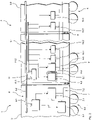
- the train assembly 1 includes a traction unit in the form of a locomotive 2 to which a number of individual cars 3 in the form of passenger cars are coupled.
- the individual wagons 3 each have a chassis 4 at both ends, so that they can be moved individually or autonomously during shunting. Furthermore, they each have a coupling device 5 at their ends, via which they can be coupled to other individual wagons 3 .
- the train set 1 includes individual wagons of different types.
- two first individual wagons 3.1 and two second individual wagons 3.2 are provided.
- a first individual carriage 3.1 and a second individual carriage 3.2 are arranged adjacent to one another and coupled to form a first carriage unit 6 in the form of a two-carriage unit.
- the first individual wagons 3.1 are designed as supply wagons that can be operated autonomously
- the second individual wagons 3.2 are designed as supplementary wagons that cannot be operated autonomously.
- the train assembly 1 includes a train energy supply device 7, via which the entire train assembly 1 is supplied with energy.
- the locomotive 2 comprises a diesel-electric unit 7.1, which represents the central energy source of the train energy supply device 7.
- This diesel-electric unit 7.1 feeds the traction drive 2.1 for the traction units 2.2 of the locomotive 2. It also feeds a train busbar 7.2, which represents a train energy distribution device of the train energy supply device 7. Starting from the locomotive 2, the train busbar 7.2 extends through all the individual wagons 3.
- the train power supply can be provided by an electric locomotive from the contact wire.
- the energy is usually converted via a transformer and fed into the train busbar.
- the train line can be connected directly to the contact wire via switching elements.
- the train assembly 1 also includes a train information supply device 8, via which the entire train assembly 1 is supplied with control information and possibly passenger information, etc.
- the locomotive 2 comprises a central computer device 8.1, which represents the central information source of the train information supply device 8.
- the central computer device 8.1 is connected to a central information line 8.2, which represents a train information distribution device of the train information supply device 8.
- This central information line can be provided both for conventional information processing (relays, etc.) and for bus signals.
- it is a train bus 8.2. Starting from the locomotive 2, the train bus 8.2 also extends through all the individual wagons 3:
- information for passenger information or other information can also be routed via the train bus system 8.2, as described above.
- train bus system 8.2 as described above.
- separate lines can also be provided for this purpose.
- the brakes are controlled across trains either via the pneumatic air line or via conventional electrical signals that are transmitted in lines. If necessary, however, the brake signals can also be transmitted via bus systems.
- the brake line main air line
- the brake line main air line
- the train information distribution device is the train information distribution device.
- All complex and/or heavy systems or components of the energy supply such as converters, rectifiers and switching elements, the vehicle battery, the battery charger, the control electronics, the brake control and possibly the passenger information are in the supply wagon 3.1 (All or parts thereof) installed that are needed to supply the supply car 3.1 and the associated supplementary car 3.2 of the respective first car unit 6 with energy and information.
- the supply wagon 3.1 thus includes a wagon energy supply device 9, via which the supply wagon 3.1 and the associated supplementary wagon 3.2 are supplied with the energy required for the consumers 10.1 to 10.4 during normal operation.
- This car power supply device 9 includes a car power source 9.1, which is fed from the train busbar 7.2.
- the car energy source 9.1 includes a frequency converter device 9.2, which generates all operationally necessary voltages for the consumers 10.1 to 10.4 from the voltage level of the train busbar 7.2 (usually: 24 V, 110 V DC, 400 V AC or 680 V DC).
- a car energy distribution device of the car energy supply device 9 connected to the car energy source 9.1 then takes over the distribution of the energy to the consumers 10.1 to 10.4.
- the carriage energy distribution device comprises an energy distribution device 9.3 connected to the frequency converter device 9.2 and a carriage busbar 9.4 fed from this.
- the carriage busbar 9.4 extends through the supply carriage 3.1 and via suitable coupling devices in the associated supplementary carriage 3.2 of the respective first carriage unit 6. The consumers 10.1 to 10.4 of the supply carriage 3.1 and the supplementary carriage 3.2 are fed from it.
- the car energy source 9.1 is dimensioned so that it can be used to supply consumers 10.1 to 10.4 of the supply car 3.1 and the associated supplementary car 3.2 during normal operation.
- the vehicle battery belonging to the vehicle energy source 9.1 for the supply vehicle 3.1 and the associated supplementary vehicle 3.2 is also housed in the supply vehicle 3.1. This is fed from a battery charger of the car energy source 9.1.
- the supply wagon 3.1 also accommodates the complex information connections that are required to control the train combination 1, the supply wagon 3.1 and the supplementary wagon 3.2 of the respective first wagon unit 6, the brakes and, if necessary, for passenger information.
- the brake control for the supply wagon 3.1 and the associated supplementary wagon 3.2 is also arranged in the supply wagon 3.1.
- a wagon information supply device 11 of the respective first wagon unit 6 is connected to the train bus 8.2.
- This car information supply device 11 comprises a coupling module in the form of a so-called gateway 11.1 and a car information distribution device in the form of a car-related bus system 11.2.
- the bus system 11.2 is a so-called car bus, the z. B. is designed as MVB (Multifunction Vehicle Bus).
- the respective car control computer with the associated diagnostic devices is also connected to this car bus 11.2.
- the systems to be controlled for the supply car 3.1 and the associated supplementary car 3.2 e.g. brakes, energy supply, doors, etc.
- the systems to be controlled include the consumers 10.1 to 10.4.
- the train bus 9.2 and the car bus 11.2 Since different information is transmitted with different levels of diagnosis and control on the two bus systems—that is, the train bus 9.2 and the car bus 11.2—the systems to be controlled for the supply car 3.1 and the associated supplementary car 3.2 cannot be connected directly to the train bus 9.2. Due to the higher data transmission rates within a vehicle, the car bus systems 11.2 cannot be extended over a long train with up to sixteen individual cars for control purposes. In addition, the number of nodes at which systems are connected to the bus is limited and not sufficient for a long train. The invention provides a remedy here through correspondingly short car bus systems 11.2, which only cover a few individual cars—two cars in the present example.
- the supply car 3.1 contains all the components required for the energy supply and the information supply to the supply car 3.1 and the associated supplementary car 3.2, it can also be used alone, d. H. be operated without a supplementary car 3.2 coupled to it.
- the supply wagons 3.1 thus represent autonomously operable individual wagons.
- the supplementary car 3.2 cannot be operated in normal operation without a supply car 3.1 coupled to it. In normal operation, it is essentially completely supplied with energy and information by the associated supply wagon 3.1. It can only be provided that, for safety reasons, it includes emergency operating devices that provide energy and information for safety-related functions, such as brakes, etc., in an emergency.
- the supplementary wagons 3.2 are therefore individual wagons that cannot be operated autonomously.
- the supply wagon 3.1 and the associated supplementary wagon 3.2 form a two-wagon unit 6. It goes without saying, however, that in other variants of the invention it can also be provided that the supply wagon with several second individual wagons, for the supply of which it is designed, to a first Wagon unit is coupled.
- the above-described design and coupling of the individual carriages 3 leads on the one hand to a clear Reducing the total mass of the train set 1.
- the energy supply device 9.1 of the respective supply car 3.1 can be designed in such a way that its mass and its production costs are significantly lower than the total mass and the production costs of the known individual energy supply devices of known individual cars. As already described above, this reduction in mass has an advantageous effect both in the production of the individual wagons 3 and in the operation of the train set 1 .
- each supply wagon 3.1 has to contain the required complex interfaces, while the supplementary wagons 3.2 have to include significantly simpler interfaces for the connection to the supply wagon.
- the number of control computers required for the car control, the information systems and, if necessary, also for the braking devices can be significantly reduced since they are only to be provided in the supply car 3.1.
- the entire equipment for the supply car 3.1 and the supplementary car 3.2 takes up less space than the entire equipment for two of the known individual cars.
- a large part of the installations is limited to the supply wagon 3.1, while hardly any installations are to be made in the supplementary wagon 3.2.
- Train group 1 is a group with four cars. It goes without saying that it can be lengthened by coupling further two-car units 6 to form a train with any even number of cars. Likewise, it goes without saying that one of the two-car units 6 can also be uncoupled, so that a combination with only two cars then arises.
- the respective two-car unit 6 can be provided at its ends with UIC-compliant interfaces.
- the two-car unit 6 can then be coupled to any other individual car like a conventional autonomous individual car.
- the two-car unit 6 then behaves like a conventional autonomous single car, but with a significantly higher transport capacity. Because of the symmetrical interfaces, the two-car unit 6 can then also be used rotated towards the outside.
- FIG 3 describes a further preferred embodiment of the train assembly 101 according to the invention, which was produced using the method for train formation according to the invention.
- This train set 101 is basically the same in structure and function as that from the figures 1 and 2 , so that only the differences will be discussed here. In particular, identical components are provided with identical reference symbols.
- the train set 101 consists of an odd number of cars. This is achieved in that a supply wagon 3.1 alone, ie without an associated supplementary wagon, is coupled into the train combination 101 in the train combination. This is possible because the supply wagons 3.1 can be operated autonomously and has the advantage that, in addition to trains with any even number of wagons, trains can also be formed with any odd number of wagons up to the operational maximum numbers.
- the second individual car or supplementary car 3.3 which cannot be operated autonomously, is designed as a control car with a driver's cab 12 in order to enable push-pull train operation.
- the supply car 3.1 and the associated control car 3.3 thus form a second car unit in the form of a control car unit 106.
- the difference between the supplementary car 3.3 designed as a control car and the supplementary car 3.2 is, among other things, that a direct connection 13 to the train bus 8.2 is provided in the area of the driver's cab 12 to connect the control devices of the driver's cab 12.
- a direct connection 13 to the train bus 8.2 is provided in the area of the driver's cab 12 to connect the control devices of the driver's cab 12.
- Other embodiments not shown here are conceivable, in which the driver's cab is connected to the car bus.
- control car 3.3 Another difference between the control car 3.3 and the supplementary car 3.2 is that the train line 7.2 is not continued in it.
- train busbar can also be continued through such a control car in other variants of the invention.
- a supply car can also be designed as a control car.
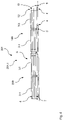
- FIG 4 describes a further preferred embodiment of the train assembly 201 according to the invention, which was produced using the method for train formation according to the invention.
- This train set 201 is basically the same in structure and functionality as that from the figures 1 and 2 or the one from figure 3 , so that only the differences will be discussed here. In particular, identical components are provided with identical reference symbols.
- a train segment 201.1 of the train 201 shows, the difference is that the train segment 201.1 in addition to a second car unit or control car unit 106, as in connection with figure 3 described, a third car unit in the form of a connecting car unit 206 comprises.
- This connecting car unit 206 comprises a supply car 3.1 and a second individual car or supplementary car 3.4 in the form of a connecting car that cannot be operated autonomously.
- the connecting car 3.4 is required if other connections are selected between the cars within the inventive train combination than at the ends to usual conventional or UIC-compliant cars. This can be the case if central buffer couplings are used within the train set, but draw hooks and side buffers are required at the ends.
- a supply trolley can also be designed as a connecting trolley.
- the connecting car 3.4 can be designed to be low-floor and connect high-floor conventional cars to corresponding other low-floor cars in a train assembly according to the invention.
- Connecting cars are always used when the interfaces within the train assembly according to the invention are different than those of conventional cars or traction units that are to be coupled with the train assembly. This is the case, for example, if the electrical interfaces, such as the voltage at the end of the train set, should be UIC-compliant, but are not within a wagon unit or the train set. Mechanical interfaces can also be different, such as the coupling, its height or the floor level. It goes without saying that a connecting car can be designed as a control car.
- train segment 201.1 can be extended by the interposition of one or more first car units 6 (see Fig Figures 1 and 3 ) or from individual supply wagons 3.1 (see figure 3 ) can be extended to any even or odd number of cars.
- the sequence of the wagons or wagon units in the train combination can be as shown here, but also rotated as desired or mirrored. Individual self-sufficient supply wagons can be added to the train at any point.
Description
Die vorliegende Erfindung betrifft ein Verfahren zur Zugbildung aus Einzelwagen ohne Traktionsausrüstung, insbesondere aus Reisezugwagen, bei dem wenigstens eine Traktionseinheit mit wenigstens einem autonom betreibbaren ersten Einzelwagen zu einem Zugverbund gekoppelt wird. Sie betrifft weiterhin einen Zugverbund, der nach diesem erfindungsgemäßen Verfahren gebildet werden kann. Schließlich betrifft sie einen Einzelwagen ohne Traktionsausrüstung für einen erfindungsgemäßen Zugverbund.The present invention relates to a method for forming a train from individual wagons without traction equipment, in particular from passenger train wagons, in which at least one traction unit is coupled to at least one autonomously operable first individual wagon to form a train combination. It also relates to a tensile assembly that can be formed using this method according to the invention. Finally, it relates to a single car without traction equipment for a train assembly according to the invention.
Bei solchen Einzelwagen ohne Traktionsausrüstung handelt es sich meist um Reisezugwagen, d. h. Wagen, die Reisende befördern, ohne einen eigenen Antrieb zu haben. Anders als bei so genannten Gliederzugwagen für Gliederzüge weisen diese Einzelwagen an beiden Enden Fahrwerke auf, sodass sie einzeln rangierbar sind. Sie werden in der Regel mit Lokomotiven oder dergleichen gekoppelt, welche die Traktion für den Zugverbund zur Verfügung stellen. Die Lokomotive versorgt dabei in der Regel die mit ihr gekoppelten Einzelwagen mit der erforderlichen Energie für die Versorgung der Bordsysteme wie Beleuchtung, Klimatisierung, Lüftung, Informationssysteme etc. Dies geschieht über eine durch den Zugverbund durchgehende Hochspannungsleitung, die so genannte Zugsammelschiene (beispielsweise 1000 V bis 3000 V, Gleich- oder Wechselspannung). Die Lokomotive übernimmt in der Regel auch die Versorgung der mit ihr gekoppelten Einzelwagen mit Steuerinformationen und gegebenenfalls weiteren Informationen. Dies geschieht über eine durch den Zugverbund durchgehende Informationsleitung, häufig einen so genannten Zugbus (z. B. WTB, Wired Train Bus nach UIC 556: "informationsübertragung im Zug - Zugbus"). Weiterhin können Informationen beispielsweise über konventionelle Leitungen, z.B. UIC 558: "Fernsteuer- und Informationsleitung; Technische Einheitsmerkmale für die Ausrüstung der RIC-Reisezugwagen", übertragen werden. Die Informationen können auch über andere Medien übertragen werden, z.B. für die Druckluftbremse durch pneumatische Leitungen oder auch hydraulische.Such single wagons without traction equipment are mostly passenger wagons, i. H. Wagons that carry travelers without having their own drive. Unlike the so-called articulated train wagons for articulated trains, these single wagons have running gears at both ends so that they can be maneuvered individually. They are usually coupled with locomotives or the like, which provide the traction for the train set. The locomotive usually supplies the individual cars coupled to it with the energy required to supply the on-board systems such as lighting, air conditioning, ventilation, information systems, etc. This is done via a high-voltage line that runs through the train set, the so-called train bus bar (e.g. 1000 V to 3000 V, DC or AC voltage). As a rule, the locomotive also supplies the individual wagons coupled to it with control information and, if necessary, additional information. This is done via an information line running through the train network, often a so-called train bus (e.g. WTB, wired train bus according to UIC 556: "information transmission in the train - train bus"). Furthermore, information can be transmitted, for example, via conventional lines, e.g. The information can also be transmitted via other media, e.g. for the compressed air brake through pneumatic lines or hydraulic lines.
Solche Reisezugwagen bestehen heute aus einem Wagenkasten von ca. 20 bis 28 m Länge. An den Enden sind Puffer und Zughaken, seltener automatische Kupplungen angebracht. Die Wagen werden einstöckig oder doppelstöckig ausgeführt. Reisezugwagen werden in Europa im Regelfall entsprechend den Forderungen der UIC ausgeführt, um durch standardisierte mechanische Schnittstellen (Puffer, Kupplung, Bremse, Übergang) und standardisierte elektrische Schnittstellen (Energieversorgung, Steuerungsleitungen, Informationsleitungen) eine universelle Austauschbarkeit und damit einen internationalen Einsatz der Wagen zu gewährleisten. Wesentliche Teile der Wagen sind in UIC 567: "Allgemeine Bestimmungen für Reisezugwagen" festgelegt. Spezielle Fragen der Energieversorgung sind in den UIC 550: "Elektrische Energieversorgungseinrichtungen für Wagen der Reisezugbauart" und UIC 552: "Versorgung der Züge mit elektrischer Energie - Technische Merkmale der Zugsammelschiene (ZS)" festgelegt.Such passenger coaches today consist of a car body of about 20 to 28 m in length. Buffers and draw hooks, less often automatic couplings, are attached to the ends. The wagons are single-deck or double-deck. In Europe, passenger coaches are generally designed in accordance with the requirements of the UIC in order to ensure universal interchangeability and thus international use of the coaches through standardized mechanical interfaces (buffers, couplings, brakes, transition) and standardized electrical interfaces (power supply, control lines, information lines). . Essential parts of the wagons are specified in UIC 567: "General provisions for passenger coaches". Specific energy supply issues are specified in UIC 550: "Electrical energy supply systems for passenger train wagons" and UIC 552: "Electrical energy supply for trains - Technical characteristics of the train busbar (ZS)".
Die bekannten Reisezugwagen werden üblicherweise als autonom betreibbare Wagen ausgeführt, d. h. jeder Wagen kann für sich alleine an eine entsprechenden Traktionseinheit gekoppelt betrieben werden. Dabei kann er mit beliebigen anderen Wagen über UIC konforme Schnittstellen gekoppelt werden. Sämtliche für den Betrieb erforderlichen Geräte sind in jedem Wagen vorhanden und für die Versorgung jeweils dieses einen Wagens ausgelegt. Dadurch können unterschiedlich lange Züge aus den unterschiedlichsten Wagen gebildet werden.The known passenger carriages are usually designed as autonomously operable carriages, d. H. each car can be operated on its own coupled to a corresponding traction unit. It can be coupled with any other wagon via UIC-compliant interfaces. All devices required for operation are present in each car and designed to supply this one car. This allows trains of different lengths to be formed from a wide variety of cars.
Zwar lässt sich mit den bekannten Reisezugwagen - anders als beispielsweise bei Gliederzügen mit mehr oder weniger fest vorgegebener Wagenreihung - eine nahezu unbegrenzte Freiheit bei der Bildung eines Zugverbundes erzielen. Die autonom betreibbare Gestaltung der Reisezugwagen bringt jedoch auch eine Reihe von Nachteilen mit sich.It is true that with the known passenger train carriages - in contrast to, for example, articulated trains with a more or less fixed carriage arrangement - an almost unlimited freedom can be achieved in the formation of a train combination. However, the autonomously operable design of the passenger coaches also has a number of disadvantages.
Durch die Ausrüstung jedes Wagens mit den erforderlichen Aggregaten für die Energieversorgung, Energieverteilung, Steuerung und Fahrgastinformation sowie mit den erforderlichen Bremsaggregaten werden die Wagen zum einen schwer, äußerst komplex und teuer.By equipping each car with the necessary units for power supply, power distribution, control and passenger information as well as with the necessary brake units, the cars are heavy, extremely complex and expensive.
Ein weiterer Nachteil tritt auf, wenn die erforderlichen Aggregate, beispielsweise bei nicht als Hochflurwagen ausgebildeten Wagen, nicht oder nicht vollständig unterhalb des Wagenbodens oder im Dachraum angeordnet werden können. Bei niederflurigen Wägen muss beispielsweise zumindest ein Teil der erforderlichen Aggregate dann in Schränken im Fahrgastraum untergebracht werden, wodurch aufgrund des dafür notwendigen Platzbedarfs die Transportkapazität des Wagens sinkt.A further disadvantage occurs when the required assemblies, for example in the case of wagons not designed as high-floor wagons, cannot be arranged, or not completely, below the wagon floor or in the roof space. In the case of low-floor wagons, for example, at least some of the necessary units then have to be accommodated in cupboards in the passenger compartment, which reduces the transport capacity of the wagon due to the space required for this.
Bei Triebzügen ist es hingegen üblich, betriebliche Einheiten zu bilden, die aus zwei oder mehreren Einzelwagen bestehen. Der Grund dafür liegt darin, daß die betriebsnotwendigen Aggregate auf beide oder mehrere Wagen verteilt werden können. Die Einzelwagen können zu Wartungszwecken getrennt werden, müssen aber wegen der Verteilung der Aggregate immer zusammen gekuppelt verkehren. So sind beispielweise die Züge der Berliner S-Bahn nach deren Elektrifizierung in der 20er Jahren mit je einem S-Wagen (Schaltwerk-Wagen) und einem K-Wagen (Kompressor-Wagen) in einem sogenannten Viertelzug ausgeführt worden. Dieses Prinzip der auf mehrere Wagen verteilten Anordnung der betriebsnotwendigen Aggregate wurde bis heute beibehalten. Ähnliche Konzepte wurden auch für andere Triebzüge und U-Bahnen angewendet.In the case of multiple units, on the other hand, it is common to form operational units that consist of two or more individual cars. The reason for this is that the units required for operation can be distributed over both or more cars. The individual wagons can be separated for maintenance purposes, but must always be coupled together because of the distribution of the aggregates. For example, the trains of the Berlin S-Bahn, after their electrification in the 1920s, were each equipped with an S car (switchgear car) and a K car (compressor car) in a so-called quarter train. This principle of distributing the units required for operation across several cars has been retained to this day. Similar concepts were also applied to other multiple units and subways.
Dieses Prinzip hat zwar den Vorteil leichterer, weniger komplexer und damit kostengünstigerer Wagen. Es bringt jedoch den Nachteil einer geringeren Flexibilität bei der Zugbildung mit sich. So können insbesondere nur Züge mit Wagenzahlen gebildet werden, die einem Vielfachen der Wagenzahl der Grundeinheiten entsprechen.This principle has the advantage of lighter, less complex and therefore cheaper cars. However, it has the disadvantage of less flexibility in train formation. In particular, only trains with car numbers can be formed that are a multiple correspond to the number of cars in the basic units.
Ein gattungsgemäßer Güterzug mit einem Versorgungswagen, der die Energieversorgung eines nicht autonom betreibbaren weiteren Güterwagens übernimmt, ist aus der
Der vorliegenden Erfindung liegt daher die Aufgabe zu Grunde, ein Verfahren zur Zugbildung, einen Zugverbund und Einzelwagen der eingangs genannten Art zur Verfügung zu stellen, welche die oben genannten Nachteile nicht oder zumindest in geringerem Maße aufweist und insbesondere bei einfacher und kostengünstiger Realisierbarkeit eine möglichst flexible Zugbildung gewährleisten.The present invention is therefore based on the object of providing a method for train formation, a train set and individual wagons of the type mentioned at the outset, which does not have the above-mentioned disadvantages or at least has them to a lesser extent and, in particular, is as flexible as possible while being simple and inexpensive to implement ensure train formation.
Die vorliegende Erfindung löst diese Aufgabe ausgehend von einem Verfahren zur Zugbildung gemäß dem Oberbegriff des Anspruchs 1 durch die im kennzeichnenden Teil des Anspruchs 1 angegebenen Merkmale. Sie löst diese Aufgabe weiterhin ausgehend von einem Zugverbund gemäß dem Oberbegriff des Anspruchs 9 durch die im kennzeichnenden Teil des Anspruchs 9 angegebenen Merkmale. Schließlich löst sie diese Aufgabe durch Einzelwagen mit den Merkmalen der Ansprüche 21 und 22 sowie durch eine Wageneinheit mit den Merkmalen des Anspruchs 23.The present invention solves this problem based on a method for train formation according to the preamble of
Der vorliegenden Erfindung liegt die technische Lehre zu Grunde, dass man bei einfacher und kostengünstiger Herstellbarkeit eine flexible Zugbildung aus Einzelwagen ohne Traktionsausrüstung ermöglicht, wenn als erster Einzelwagen ein Versorgungswagen verwendet wird, der zur Übernahme im Wesentlichen der gesamten Energieversorgung und Informationsversorgung wenigstens eines nicht autonom betreibbaren zweiten Einzelwagens im Normalbetrieb ausgebildet ist.The present invention is based on the technical teaching that flexible train formation from individual wagons without traction equipment is made possible with simple and cost-effective manufacturability if a supply wagon is used as the first individual wagon, which to take over essentially the entire energy supply and information supply of at least one non-autonomously operable second individual car is formed in normal operation.
Zur Energieversorgung der Wagen wird heute überwiegend elektrische Energie verwendet. Andere Energieformern sind zum Beispiel pneumatische Energie, die beispielsweise für die Bremsversorgung und/oder die Luftfeder und andere Antriebe eingesetzt wird. Diese wird über die eine durchgehende Luftleitung, die sogenannte Hauptluftbehälterleitung, übertragen. Auch hydraulische Energie kann bereitgestellt und im Zugverband verwendet werden.Electrical energy is predominantly used today to supply the cars with energy. Other forms of energy are, for example, pneumatic energy, which is used, for example, for the brake supply and/or the air spring and other drives. This is transmitted via the one continuous air line, the so-called main air reservoir line. Hydraulic energy can also be provided and used in the train set.
Im Zugverband verwendete Informationen sind beispielsweise solche über den Zustand des Zuges, zum Steuern des Zugverbandes und einzelner in ihm angeordneter Systeme, die Diagnose oder solche zur Information der Passagiere und/oder des Zugpersonals. Diese werden üblicherweise elektrisch über konventionelle Steuerleitungen zum Beispiel über Relais übertragen oder über digitale Bussysteme. Für pneumatisch gesteuerte Bremssysteme oder elektropneumatisch gesteuerte Bremssysteme werden Bremsinforationen über eine Druckluftleitung, die sogenannte Hauptluftleitung, übertragen.Information used in the train set is, for example, information about the status of the train, for controlling the train set and individual systems arranged in it, diagnostics or information for the passengers and/or the train crew. These are usually transmitted electrically via conventional control lines, for example via relays, or via digital bus systems. For pneumatically controlled braking systems or electropneumatically controlled braking systems, braking information is transmitted via a compressed air line, the so-called main air line.
Der Versorgungswagen ist hierbei erfindungsgemäß so ausgebildet, dass er im Normalbetrieb im Wesentlichen die gesamte Energieversorgung und/oder im Wesentlichen die gesamte Informationsversorgung wenigstens eines nicht autonom betreibbaren zweiten Einzelwagens übernimmt, der hier im Folgenden auch als Ergänzungswagen bezeichnet wird. Es versteht sich hierbei jedoch, dass der jeweilige zweiten Einzelwagen aus Sicherheitsgründen entsprechende Notversorgungseinrichtungen für den - gegebenenfalls kurzzeitigen - Notbetrieb aufweisen kann. Darüber hinaus können Ergänzungswagen auch einzelne System enthalten, die Teilaufgaben im Ergänzungswagen autark vom Versorgungswagen realisieren. So kann beispielsweise die Energieversorgung nur in den Versorgungswagen angeordnet sein, um die Ergänzungswagen mit zu versorgen, aber die Bremssteuerung in jedem Wagen des Zugverbundes, auch im Ergänzungswagen, angeordnet sein.According to the invention, the supply car is designed such that during normal operation it essentially takes over the entire energy supply and/or essentially the entire information supply of at least one second individual car that cannot be operated autonomously, which is also referred to here as a supplementary car. It goes without saying here, however, that the respective second individual wagon can have corresponding emergency supply devices for emergency operation, which may be brief, for safety reasons. In addition, supplementary wagons can also contain individual systems that implement subtasks in the supplementary wagon independently of the supply wagon. For example, the energy supply can only be arranged in the supply wagons in order to also supply the supplementary wagons, but the brake control can be arranged in each wagon of the train set, including the supplementary wagon.
Der erfindungsgemäße Versorgungswagen kann mit einem oder mehreren zweiten Einzelwagen, für deren Versorgung er ausgelegt ist, zu einer ersten Wageneinheit gekoppelt werden, die eine Reihe von Vorteilen gegenüber einer gekoppelten Einheit aus derselben Anzahl bekannter autonom betreibbarer Einzelwagen mit sich bringt.The supply wagon according to the invention can be coupled with one or more second individual wagons for whose supply it is designed to form a first wagon unit, which has a number of advantages over a coupled unit made up of the same number of known autonomously operable individual wagons.
So führt sie zum einen zu einer deutlichen Verringerung der Gesamtmasse des Zugverbunds. So kann die Energieversorgungseinrichtung des Versorgungswagens, die mit höherer Leistung zur Versorgung der Wagen der ersten Wageneinheit ausgestattet ist, so ausgeführt werden, dass ihre Masse deutlich geringer ist als die Gesamtmasse der bekannten Einzelenergieversorgungseinrichtungen der Einzelwagen. Diese Massenreduktion macht sich nicht nur bei der Herstellung der Wagen sondern insbesondere auch bei Beschleunigungsvorgängen des Zugverbunds bemerkbar. So wird dadurch zum einen Energie eingespart. Zudem kann die Bremsausrüstung wiederum entsprechend leichter dimensioniert werden, was zu einer weiteren Massenreduktion führt.On the one hand, it leads to a significant reduction in the overall mass of the train set. The energy supply device of the supply car, which is equipped with higher power to supply the cars of the first car unit, can be designed so that its mass is significantly lower than the total mass of the known individual energy supply devices of the individual cars. This reduction in mass is not only noticeable in the manufacture of the wagons, but also in particular when the train is accelerated. On the one hand, this saves energy. In addition, the brake equipment can in turn be dimensioned correspondingly lighter, which leads to a further reduction in mass.
Da die Kosten für die elektrische Ausrüstung, gegebenenfalls auch für die pneumatische Ausrüstung und/oder sonstige Medienversorgungsausrüstungen, den Wagenherstellungspreis wesentlich beeinflussen, können mit der vorliegenden Erfindung die Herstellungskosten gesenkt werden. So ist eine Ausrüstung mehrfacher Leistung deutlich günstiger herzustellen, als eine entsprechende Anzahl von Ausrüstungen einfacher Leistung. Gleiches gilt für die erforderlichen Einbauten für die Integration der Ausrüstung in die Wagen (Gehäuse, Schränke, Schalttafeln, Umrichter, Lüfter etc.), die Montage der Ausrüstungen und deren Inbetriebsetzung.Since the costs for the electrical equipment, optionally also for the pneumatic equipment and/or other media supply equipment, have a significant influence on the car production price, the production costs can be reduced with the present invention. Thus, equipment with multiple performance is significantly cheaper to produce than a corresponding number of equipment with single performance. The same applies to the installations required to integrate the equipment into the wagons (housings, cabinets, switchboards, converters, fans, etc.), the assembly of the equipment and its commissioning.
Weiterhin reduziert sich auch der Aufwand für die Anbindung der Wagen an die Zugenergieversorgung und die Zugsteuerung deutlich. So muss nur jeder Versorgungswagen die erforderlichen aufwändigen Schnittstellen, wie beispielsweise Hauptschalter, Erdungseinrichtung, aber auch Kuppeldosen, enthalten, während die Ergänzungswagen deutlich einfachere Schnittstellen für die Anbindung an den Versorgungswagen umfassen müssen. Auch die Anzahl der erforderlichen Steuerrechner (für Wagensteuerung, Informationssysteme und ggf. auch für die Bremseinrichtungen) kann deutlich reduziert werden, da sie jeweils nur in dem Versorgungswagen vorzusehen sind. Werden Versorgungswagen zum autarken Einsatz vorgesehen, können einige Schnittstellen an den Wagenenden gegebenenfalls vereinfacht ausgeführt werden.Furthermore, the effort involved in connecting the wagons to the train energy supply and the train control system is significantly reduced. Each supply wagon only has to contain the necessary complex interfaces, such as the main switch, earthing device, but also dome sockets, while the supplementary wagons must have significantly simpler interfaces for connecting to the supply wagon. The number of control computers required (for wagon control, information systems and, if applicable, also for the braking devices) can be significantly reduced, since they are only to be provided in the supply wagon. If supply wagons are intended for self-sufficient use, some interfaces at the ends of the wagon can be simplified if necessary.
Insgesamt nimmt die gesamte Ausrüstung für die erste Wageneinheit weniger Bauraum ein als die gesamte Ausrüstung für die bekannten Einzelwagen. Insbesondere bei niederflurigen Wagen ist der Einbau der Ausrüstung in Schränken im Fahrgastraum günstiger zu gestalten. So beschränkt sich ein Großteil der Einbauten auf den Versorgungswagen, während in den Ergänzungswagen kaum Einbauten vorzunehmen sind. Wegen der beschriebenen insgesamt geringeren Anzahl und Masse der Ausrüstungen und damit dem insgesamt geringeren erforderlichen Bauraum für die Ausrüstungen der ersten Wageneinheit steht insgesamt mehr Nutzfläche in der Wageneinheit zur Verfügung.Overall, the entire equipment for the first car unit takes up less space than the entire equipment for the known individual cars. In the case of low-floor wagons in particular, it is cheaper to install the equipment in cabinets in the passenger compartment. A large part of the installations is limited to the supply car, while hardly any installations are to be made in the supplementary cars. Because of the overall lower number and mass of equipment described and thus the overall smaller installation space required for the equipment of the first car unit, there is more usable space available in the car unit overall.
Ein weiterer Vorteil der vorliegenden Erfindung gegenüber den bekannten Triebzügen mit verteilter Ausrüstung liegt in der autonomen Betreibbarkeit der Versorgungswagen. Diese können auch einzeln, d. h. ohne Ergänzungswagen in den Zugverbund eingebunden werden, sodass Züge mit beliebiger geradzahliger oder ungeradzahliger Wagenanzahl bis hin zu den betrieblichen Maximalzahlen gebildet werden können.A further advantage of the present invention over the known multiple units with distributed equipment lies in the autonomous operability of the supply cars. These can also be used individually, i. H. be integrated into the train network without additional cars, so that trains can be formed with any even or odd number of cars up to the operational maximum numbers.
Der Vorteil gegenüber Gliederzügen liegt darin, dass die erfindungsgemäß verwendeten Wagen Einzelwagen sind und daher nach wie vor wie bekannte Einzelwagen rangiert und gewartet werden können. Entsprechend den betrieblichen Notwendigkeiten können Züge verstärkt und geschwächt werden. So sind Züge mit bis zu 16 Wagen möglich, je nach Leistungsfähigkeit der Lokomotive und deren Energieversorgung bzw. entsprechend der Infrastruktur oder der Steuerungselektronik,The advantage over articulated trains is that the carriages used according to the invention are individual carriages and can therefore still be shunted and maintained as known individual carriages. Trains can be strengthened and weakened according to operational needs. Trains with up to 16 cars are possible, depending on the performance of the locomotive and its power supply or according to the infrastructure or the control electronics.
Der Versorgungswagen kann grundsätzlich zur Versorgung einer beliebigen Anzahl von zweiten Einzelwagen ausgelegt sein. Eine besonders flexible Zuggestaltung bei kostengünstiger Herstellbarkeit der Wagen ist jedoch möglich, wenn der Versorgungswagen zur Energieversorgung und/oder Informationsversorgung genau eines nicht autonom betreibbaren zweiten Einzelwagens im Normalbetrieb ausgebildet ist. Da der Aufwand für die Versorgung mehrerer Wagen mit der Wagenanzahl überproportional steigt, ist mit dieser Zweierkonfiguration auch eine besonders kostengünstige Herstellbarkeit der Wagen gewährleistet.In principle, the supply wagon can be designed to supply any number of second individual wagons. However, a particularly flexible train design with cost-effective manufacturability of the wagons is possible if the supply wagon is designed to supply energy and/or information to exactly one second individual wagon that cannot be operated autonomously in normal operation. Since the cost of supplying several cars increases disproportionately with the number of cars, this two-car configuration also ensures that the cars can be manufactured at particularly low cost.
Die Minimalkonfiguration eines Zugverbunds, der mit dem erfindungsgemäßen Verfahren hergestellt werden kann, ist demgemäß ein Zug mit einer Traktionseinrichtung, beispielsweise einer Lokomotive, und einem damit gekoppelten Versorgungswagen. Der Versorgungswagen wird mit wenigstens einem nicht autonom betreibbaren zweiten Einzelwagen zu einer ersten Wageneinheit gekoppelt. Der zweite Einzelwagen ist dabei derart ausgebildet, dass im Normalbetrieb im Wesentlichen seine gesamte Energieversorgung und/oder Informationsversorgung durch den Versorgungswagen erfolgt. Derartige im Normalbetrieb durch den Versorgungswagen versorgte, nicht autonom betreibbare zweite Einzelwagen werden im Folgenden auch als Ergänzungswagen bezeichnet.The minimum configuration of a train assembly that can be produced using the method according to the invention is accordingly a train with a traction device, for example a locomotive, and a supply wagon coupled thereto. The supply trolley is coupled with at least one second individual trolley that cannot be operated autonomously to form a first trolley unit. The second individual carriage is designed in such a way that during normal operation it is essentially supplied with energy and/or information by the supply carriage. Such second individual wagons that are supplied by the supply wagon during normal operation and cannot be operated autonomously are also referred to below as supplementary wagons.
Aus den oben bereits erläuterten Gründen werden dabei bevorzugt ein Versorgungswagen und ein Ergänzungswagen gekoppelt, sodass die erste Wageneinheit bevorzugt als Zweiwageneinheit mit einem Versorgungswagen und einem Ergänzungswagen ausgebildet ist.For the reasons already explained above, a supply trolley and a supplementary trolley are preferably coupled, so that the first trolley unit is preferably designed as a two-trolley unit with a supply trolley and a supplementary trolley.
Um die oben geschilderten Vorteile besonders zum Trägen kommen zu lassen, wird bevorzugt ein Zugverbund gebildet, der eine Mehrzahl von ersten Wageneinheiten umfasst. Weiterhin ist zur Erzielung einer beliebigen Wagenanzahl bevorzugt vorgesehen, dass ein Zugverbund gebildet wird, der wenigstens einen nicht in einer ersten Wageneinheit eingebundenen Versorgungswagen umfasst.In order to make the above-described advantages particularly effective, a train assembly is preferably formed which comprises a plurality of first car units. Furthermore, in order to achieve any number of wagons, it is preferably provided that a train combination is formed which comprises at least one supply wagon that is not integrated into a first wagon unit.
Die erfindungsgemäß gestalteten Einzelwagen können grundsätzlich beliebige Funktionen und Gestaltungen aufweisen. So kann es sich um Einzelwagen üblicher hochfluriger, einstöckiger oder doppelstöckiger Bauform mit UIC-konformem Gummiwulst-Übergang oder Faltbalgübergängen handeln. Ebenso kann es sich um Wagen niederfluriger Bauart handeln. Weiterhin kann es sich um ein- oder doppelstöckige Steuerwagen handeln. Ebenso sind Sonderbauformen aufgrund spezieller Zugkonzepte realisierbar, z. B. niederflurige Anschluss- und/oder Steuerwagen.In principle, the individual wagons designed according to the invention can have any desired functions and designs. It can be a single wagon of the usual high-floor, single-deck or double-deck design with UIC-compliant rubber bead transitions or bellows transitions. It can also be low-floor wagons. Furthermore, it can be a single- or double-decker control car. Special designs can also be implemented due to special train concepts, e.g. B. low-floor connecting and/or control cars.
Dabei können insbesondere sowohl Ergänzungswagen als auch Versorgungswagen als Steuerwagen ausgeführt werden, um einen Wendezug- oder Flügelzugbetrieb zu ermöglichen. Um auch in einem solchen Steuerwagen noch eine hohe Transportkapazität zur Verfügung zu stellen, ist dieser bevorzugt durch einen Ergänzungswagen realisiert. Bevorzugt wird daher ein Versorgungswagen mit einem zweiten Einzelwagen zu einer zweiten Wageneinheit gekoppelt, wobei der zweite Einzelwagen als im Normalbetrieb nicht autonom betreibbarer Steuerwagen ausgebildet ist.In particular, both supplementary cars and supply cars can be designed as control cars in order to enable push-pull or wing train operation. In order to still provide a high transport capacity in such a control car, this is preferably realized by an additional car. A supply wagon is therefore preferably coupled to a second individual wagon to form a second wagon unit, with the second individual wagon being designed as a control wagon which cannot be operated autonomously during normal operation.
Die vorliegende Erfindung betrifft weiterhin einen Zugverbund aus Einzelwagen ohne Traktionsausrüstung, insbesondere aus Reisezugwagen, mit wenigstens einer Traktionseinheit und wenigstens einem mit der Traktionseinheit gekoppelten autonom betreibbaren ersten Einzelwagen. Erfindungsgemäß ist vorgesehen, dass der erste Einzelwagen ein Versorgungswagen ist, der zur Übernahme im Wesentlichen der gesamten Energieversorgung und Informationsversorgung wenigstens eines nicht autonom betreibbaren zweiten Einzelwagens im Normalbetrieb ausgebildet ist.The present invention also relates to a train set made up of individual cars without traction equipment, in particular passenger cars, with at least one traction unit and at least one autonomously operable first individual car coupled to the traction unit. According to the invention, it is provided that the first individual wagon is a supply wagon which is designed to take over essentially the entire energy supply and information supply of at least one second individual wagon which cannot be operated autonomously during normal operation.
Dieser erfindungsgemäße Zugverbund lässt sich mit dem oben beschriebenen erfindungsgemäßen Verfahren herstellen. Mit ihm lassen sich die oben beschriebenen Vorteile und Varianten in demselben Maße realisieren, sodass diesbezüglich auf die obigen Ausführungen Bezug genommen wird.This tensile assembly according to the invention can be produced using the method according to the invention described above. With it, the advantages and variants described above can be realized to the same extent, so that the above explanations apply in this regard is referred to.
Die Versorgung des ersten Einzelwagens, also des Versorgungswagens, mit Energie und/oder Informationen kann auf beliebige geeignete Weise erfolgen. So kann eine autonome interne Versorgung ebenso vorgesehen sein, wie eine externe Versorgung über eine entsprechende geeignete Schnittstelle. Üblicherweise erfolgt über eine oder mehrere geeignete Schnittstellen eine Versorgung durch die Traktionseinheit des Zugverbunds. Bevorzugt ist daher vorgesehen, dass der erste Einzelwagen zur Energieversorgung und/oder Informationsversorgung durch die Traktionseinheit ausgebildet ist.The first individual wagon, ie the supply wagon, can be supplied with energy and/or information in any suitable manner. Thus, an autonomous internal supply can be provided as well as an external supply via a corresponding suitable interface. Supply is usually provided by the traction unit of the train set via one or more suitable interfaces. It is therefore preferably provided that the first individual carriage is designed for the supply of energy and/or information by the traction unit.
Die Energieversorgung der Einzelwagen kann auf beliebige geeignete Weise über die Versorgungswagen erfolgen. Bei bevorzugten Varianten des erfindungsgemäßen Zugverbunds ist zur Energieversorgung der Einzelwagen eine Zugenergieversorgungseinrichtung vorgesehen. Diese Zugenergieversorgungseinrichtung kann beispielsweise einen entsprechenden Generator, Wechsel- oder Gleichrichter umfassen, der sich beispielsweise in der Traktionseinheit, z. B einer Lokomotive, oder einen weiteren Wagen befindet. Diese Zugenergieversorgungseinrichtung umfasst weiterhin eine Zugenergieverteilungseinrichtung, insbesondere eine Zugsammelschiene, welche die Energieverteilung zu den Versorgungswagen sicherstellt.. Der Versorgungswagen umfasst dann eine erste Wagenenergieversorgungseinrichtung, die zur Energieversorgung des Versorgungswagens mit der Zugenergieverteilungseinrichtung verbunden ist. Hierdurch kann eine besonders einfache Energieversorgung der Einzelwagen realisiert werden.The power supply to the individual wagons can take place in any suitable way via the supply wagons. In preferred variants of the train combination according to the invention, a train energy supply device is provided for supplying energy to the individual cars. This train power supply device can include, for example, a corresponding generator, inverter or rectifier, for example, in the traction unit, z. B a locomotive, or another car is located. This train energy supply device also includes a train energy distribution device, in particular a train busbar, which ensures the distribution of energy to the supply wagons. In this way, a particularly simple power supply for the individual carriages can be implemented.
Bevorzugt ist wenigstens ein Versorgungswagen mit wenigstens einem zweiten Einzelwagen zu wenigstens einer ersten Wageneinheit gekoppelt. Der Versorgungswagen umfasst dabei eine erste Wagenenergieversorgungseinrichtung, die zur Energieversorgung des Versorgungswagens und des Ergänzungswagens ausgebildet ist, sowie eine Wagenenergieverteilungseinrichtung, insbesondere eine Wagensammeischiene. Der Ergänzungswagen ist dann zur Energieversorgung mit der Wagenenergieverteilungseinrichtung verbunden, um eine einfach gestaltete Energieversorgung des Ergänzungswagens zu realisieren.At least one supply trolley is preferably coupled to at least one second individual trolley to form at least one first trolley unit. The supply car includes a first car power supply device, which is designed to supply power to the supply car and the supplementary car, and a car power distribution device, in particular a car busbar. The supplementary carriage is then connected to the carriage energy distribution device for the energy supply, in order to implement a simply designed energy supply for the supplementary carriage.
Bei nicht erfindungsgemäßen Gestaltungen kann die Informationsversorgung der Einzelwagen auf beliebige geeignete Weise über die Versorgungswagen erfolgen. So kann auch hier eine autonome Informationsversorgung in jedem oder einzelnen Versorgungswagen vorgesehen sein. Erfindungsgemäß ist jedoch eine zentrale Zuginformationsversorgungseinrichtung vorgesehen. Diese kann beispielsweise einen Zentralrechner oder dergleichen umfassen, der sich beispielsweise in der Traktionseinheit, z. B. einer Lokomotive, befindet. Ein zur Zuginformationsversorgungseinrichtung gehörender Rechner kann aber auch in einem der Einzelwagen angeordnet sein. Dies kann insbesondere dann der Fall sein, wenn ein Steuerwagen vorgesehen ist, in dem dann bevorzugt ein entsprechender zur Zuginformationsversorgungseinrichtung gehörender Steuerrechner angeordnet ist.In the case of configurations that are not in accordance with the invention, the information can be supplied to the individual wagons in any suitable manner via the supply wagons. Here, too, an autonomous supply of information can be provided in each or individual supply vehicle. According to the invention, however, a central train information supply device is provided. This can include, for example, a central computer or the like, which is located, for example, in the traction unit, e.g. B. a locomotive is located. However, a computer belonging to the train information supply device can also be arranged in one of the individual cars. This can be the case in particular when a control car is provided, in which a corresponding control computer belonging to the train information supply device is then preferably arranged.
Die Zuginformationsversorgungseinrichtung umfasst dann weiterhin eine Zuginformationsvertei-lungseinrichtung, die ein Zugbus ist über welche die entsprechenden Informationen an die Versorgungswagen verteilt werden. Hierbei kann es sich um eine drahtlose und/oder eine drahtgebundene Verteilungseinrichtung handeln.The train information supply device then also includes a train information distribution device, which is a train bus via which the corresponding information is distributed to the supply wagons. This can be a wireless and/or wired distribution device.
Der Versorgungswagen umfasst dann wiederum eine erste Wageninformationsversorgungseinrichtung, die zur Informationsversorgung des Versorgungswagens mit der Zuginformationsverteilungseinrichtung verbunden ist.The service car then in turn comprises a first car information supply device, which is connected to the train information distribution device for supplying information to the service car.
Der Versorgungswagen ist mit wenigstens einem zweiten Einzelwagen zu einer ersten Wageneinheit gekoppelt. Der Versorgungswagen umfasst dann eine erste Wageninformationsversorgungseinrichtung, die zur Informationsversorgung des Versorgungswagens und des Ergänzungswagens ausgebildet ist und eine Wageninformationsverteilungseinrichtung, die ein Wagenbus ist, umfasst. Der Ergänzungswagen ist dann zur Informationsversorgung mit der Wageninformationsverteilungseinrichtung verbunden. Die Wageninformationsversorgungseinrichtung kann dabei wegen der geringen Anzahl an zu versorgenden Wagen entsprechend einfach und mit hohen Übertragungsraten gestaltet werden. Hierdurch kann eine einfache, gute und schnelle Informationsversorgung der Ergänzungswagen gewährleistet werden.The supply carriage is coupled with at least one second individual carriage to form a first carriage unit. The supply car then includes a first car information supply device, which is designed to supply information to the supply car and the supplementary car and includes a car information distribution device, which is a car bus. The supplementary car is then connected to the car information distribution device for supplying information. Because of the small number of cars to be supplied, the car information supply device can be designed in a correspondingly simple manner and with high transmission rates. In this way, a simple, good and quick supply of information to the supplementary wagons can be guaranteed.
Die Traktionseinheit kann ein beliebiges Schienenfahrzeug sein, welches entsprechende Traktionseinrichtungen wie Motoren und davon angetriebene Radsätze aufweist. Bevorzugt handelt es sich bei der Traktionseinheit um eine Lokomotive oder einen Triebwagen.The traction unit can be any rail vehicle that has appropriate traction devices such as motors and wheel sets driven by them. The traction unit is preferably a locomotive or a railcar.
Die vorliegende Erfindung betrifft weiterhin einen Einzelwagen ohne Traktionsausrüstung, insbesondere einen Reisezugwagen, der als autonom betreibbarer erster Einzelwagen eines erfindungsgemäßen Zugverbunds ausgebildet ist. Als solcher weist er die oben beschriebenen Merkmale eines ersten Einzelwagens des erfindungsgemäßen Zugverbunds auf.The present invention further relates to a single wagon without traction equipment, in particular a passenger train wagon, which is designed as an autonomously operable first single wagon of a train assembly according to the invention. As such, it has the features described above of a first individual car of the train combination according to the invention.
Die vorliegende Erfindung betrifft weiterhin einen Einzelwagen ohne Traktionsausrüstung, insbesondere einen Reisezugwagen, der als nicht autonom betreibbarer zweiter Einzelwagen eines erfindungsgemäßen Zugverbunds ausgebildet ist. Als solcher weist er die oben beschriebenen Merkmale eines zweiten Einzelwagens des erfindungsgemäßen Zugverbunds auf.The present invention further relates to a single wagon without traction equipment, in particular a passenger train wagon, which is designed as a second single wagon of a train assembly according to the invention that cannot be operated autonomously. As such, it has the features described above of a second individual car of the train combination according to the invention.
Weiterhin betrifft die Erfindung eine Wageneinheit aus einem erfindungsgemäßen ersten Einzelwagen und wenigstens einem erfindungsgemäßen zweiten Einzelwagen.Furthermore, the invention relates to a wagon unit made up of a first individual wagon according to the invention and at least one second individual wagon according to the invention.
Diese erfindungsgemäßen Einzelwagen bzw. Wageneinheiten lassen sich zur Herstellung des oben beschriebenen erfindungsgemäßen Zugverbunds mit dem oben beschriebenen erfindungsgemäßen Verfahren einsetzten. Mit ihnen lassen sich die oben beschriebenen Vorteile und Varianten in demselben Maße realisieren, sodass diesbezüglich auf die obigen Ausführungen Bezug genommen wird.These individual wagons or wagon units according to the invention can be used to produce the train combination according to the invention described above using the method according to the invention described above. With them, the advantages and variants described above can be realized to the same extent, so that reference is made in this regard to the above statements.
Weitere bevorzugte Ausgestaltungen der Erfindung ergeben sich aus den Unteransprüchen bzw. der nachstehenden Beschreibung eines bevorzugten Ausführungsbeispiels, welche auf die beigefügten Zeichnungen Bezug nimmt. Es zeigen
Figur 1- eine schematische Darstellung einer bevorzugten Ausführungsform des erfindungsgemäßen Zugverbunds, der mit dem erfindungsgemäßen Verfahren zur Zugbildung hergestellt wurde;
Figur 2- eine schematische Darstellung eines Teils des Zugverbunds aus
Figur 1 ; Figur 3- eine schematische Darstellung einer weiteren bevorzugten Ausführungsform des erfindungsgemäßen Zugverbunds, der mit dem erfindungsgemäßen Verfahren zur Zugbildung hergestellt wurde;
Figur 4- eine schematische Darstellung eines Teils einer weiteren bevorzugten Ausführungsform des erfindungsgemäßen Zugverbunds, der mit dem erfindungsgemäßen Verfahren zur Zugbildung hergestellt wurde.
- figure 1
- a schematic representation of a preferred embodiment of the tensile composite according to the invention, which was produced with the method according to the invention for train formation;
- figure 2
- shows a schematic representation of part of the train set
figure 1 ; - figure 3
- a schematic representation of a further preferred embodiment of the tensile composite according to the invention, which was produced with the method according to the invention for train formation;
- figure 4
- a schematic representation of part of a further preferred embodiment of the train assembly according to the invention, which was produced with the method according to the invention for train formation.
Im Folgenden wird zunächst unter Bezugnahme auf die
Der Zugverbund 1 umfasst eine Traktionseinheit in Form einer Lokomotive 2, an die eine Reihe von Einzelwagen 3 in Form von Reisezugwagen gekoppelt sind. Die Einzelwagen 3 weisen an ihren beiden Enden jeweils ein Fahrwerk 4 auf, sodass sie im Rangierbetrieb einzeln bzw. autonom verschoben werden können. Weiterhin weisen sie an ihren Enden je eine Kupplungseinrichtung 5 auf, über die sie mit anderen Einzelwagen 3 gekoppelt werden können.The
Der Zugverbund 1 umfasst Einzelwagen unterschiedlicher Art. So sind im gezeigten Beispiel zwei erste Einzelwagen 3.1 und zwei zweite Einzelwagen 3.2 vorgesehen. Jeweils ein erster Einzelwagen 3.1 und ein zweiter Einzelwagen 3.2 sind benachbart zueinander angeordnet und zu einer ersten Wageneinheit 6 in Form einer Zweiwageneinheit gekoppelt. Wie im Folgenden noch näher erläutert wird, sind die ersten Einzelwagen 3.1 als autonom betreibbare Versorgungswagen ausgebildet, während die zweiten Einzelwagen 3.2 als nicht autonom betreibbare Ergänzungswagen ausgebildet sind.The
Der Zugverbund 1 umfasst eine Zugenergieversorgungseinrichtung 7, über die der gesamte Zugverbund 1 mit Energie versorgt wird. Die Lokomotive 2 umfasst in diesem Ausführungsbeispiel ein dieselelektrisches Aggregat 7.1, das die zentrale Energiequelle der Zugenergieversorgungseinrichtung 7 darstellt. Dieses dieselelektrische Aggregat 7.1 speist zum einen den Traktionsantrieb 2.1 für die Triebfahrwerke 2.2 der Lokomotive 2. Weiterhin speist sie eine Zugsammelschiene 7.2, welche eine Zugenergieverteilungseinrichtung der Zugenergieversorgungseinrichtung 7 darstellt. Die Zugsammelschiene 7.2 erstreckt sich ausgehend von der Lokomotive 2 durch sämtliche Einzelwagen 3 hindurch.The
In anderen, hier nicht näher ausgeführten Beispielen kann die Zugenergieversorgung über eine elektrische Lokomotive aus dem Fahrdraht geschehen. Dabei wird in der Regel die Energie bei Wechselstromversorgung über einen Transformator umgeformt und in die Zugsammelschiene gespeist. Bei Gleichstromspeisung kann die Zugsammelschiene über Schaltelemente direkt an den Fahrdraht geschaltet werden.In other examples that are not detailed here, the train power supply can be provided by an electric locomotive from the contact wire. In the case of AC power supply, the energy is usually converted via a transformer and fed into the train busbar. With DC power supply, the train line can be connected directly to the contact wire via switching elements.
Der Zugverbund 1 umfasst weiterhin eine Zuginformationsversorgungseinrichtung 8, über die der gesamte Zugverbund 1 mit Steuerungsinformationen sowie gegebenenfalls Fahrgastinformationen etc. versorgt wird. Die Lokomotive 2 umfasst hierzu eine Zentralrechnereinrichtung 8.1, welche die zentrale Informationsquelle der Zuginformationsversorgungseinrichtung 8 darstellt. Die Zentralrechnereinrichtung 8.1 ist mit einer zentralen Informationsleitung 8.2 verbunden, die eine Zuginformationsverteilungseinrichtung der Zuginformationsversorgungseinrichtung 8 darstellt.The
Diese zentrale Informationsleitung kann sowohl für konventionelle Informationsverarbeitung (Relais etc.) vorgesehen sein als auch für Bussignale. Im vorliegenden Beispiel ist sie ein Zugbus 8.2. Der Zugbus 8.2 erstreckt sich ausgehend von der Lokomotive 2 ebenfalls durch sämtliche Einzelwagen 3 hindurch:This central information line can be provided both for conventional information processing (relays, etc.) and for bus signals. In the present example it is a train bus 8.2. Starting from the
Über das Zugbussystem 8.2 kann wie erwähnt auch Information zur Fahrgastinformation oder andere Informationen wie oben dargestellt geleitet werden. Es können dafür aber auch separate Leitungen vorgesehen sein.As mentioned, information for passenger information or other information can also be routed via the train bus system 8.2, as described above. However, separate lines can also be provided for this purpose.
Ähnliches gilt für die Bremssteuerung. Die Bremssteuerung geschieht zugübergreifend entweder über die pneumatische Luftleitung oder über konventionelle elektrische Signale, die in Leitungen übertragen werden. Gegebenenfalls können aber auch die Bremssignale über Bussysteme übertragen werden. Damit ist bei der pneumatischen Informationsübertragung beispielsweise die Bremsleitung (Hauptluftleitung) die Zuginformationsverteilungseinrichtung.The same applies to the brake control. The brakes are controlled across trains either via the pneumatic air line or via conventional electrical signals that are transmitted in lines. If necessary, however, the brake signals can also be transmitted via bus systems. In the case of pneumatic information transmission, for example, the brake line (main air line) is the train information distribution device.
In den Versorgungswagen 3.1 sind sämtliche aufwändigen und/oder schweren Systeme bzw. Komponenten der Energieversorgung, wie beispielsweise Umrichter, Gleichrichter und Schaltelemente, der Fahrzeugbatterie, des Batterieladegeräts, der Steuerungselektronik, der Bremssteuerung und gegebenenfalls der Fahrgastinformation (alle oder auch Teile davon) eingebaut, die benötigt werden, um den Versorgungswagen 3.1 und den zugehörigen Ergänzungswagen 3.2 der jeweiligen ersten Wageneinheit 6 mit Energie und Informationen zu versorgen.All complex and/or heavy systems or components of the energy supply, such as converters, rectifiers and switching elements, the vehicle battery, the battery charger, the control electronics, the brake control and possibly the passenger information are in the supply wagon 3.1 (All or parts thereof) installed that are needed to supply the supply car 3.1 and the associated supplementary car 3.2 of the respective
So umfasst der Versorgungswagen 3.1 jeweils eine Wagenenergieversorgungseinrichtung 9, über die der Versorgungswagen 3.1 und der zugehörige Ergänzungswagen 3.2 mit der im Normalbetrieb nötigen Energie für die Verbraucher 10.1 bis 10.4 versorgt wird. Diese Wagenenergieversorgungseinrichtung 9 umfasst eine Wagenenergiequelle 9.1, die aus der Zugsammelschiene 7.2 gespeist wird.The supply wagon 3.1 thus includes a wagon
Die Wagenenergiequelle 9.1 umfasst eine Frequenzumrichtereinrichtung 9.2, die aus dem Spannungsniveau der Zugsammelschiene 7.2 alle betrieblich notwendigen Spannungen für die Verbraucher 10.1 bis 10.4 erzeugt (in der Regel: 24 V, 110 V DC, 400 V AC oder auch 680 V DC).The car energy source 9.1 includes a frequency converter device 9.2, which generates all operationally necessary voltages for the consumers 10.1 to 10.4 from the voltage level of the train busbar 7.2 (usually: 24 V, 110 V DC, 400 V AC or 680 V DC).
Eine mit der Wagenenergiequelle 9.1 verbundene Wagenenergieverteilungseinrichtung der Wagenenergieversorgungseinrichtung 9 übernimmt dann die Verteilung der Energie an die Verbraucher 10.1 bis 10.4. Die Wagenenergieverteilungseinrichtung umfasst eine mit der Frequenzumrichtereinrichtung 9.2 verbundene Energieverteilungseinrichtung 9.3 und eine aus dieser gespeiste Wagensammelschiene 9.4. Die Wagensammelschiene 9.4 erstreckt sich durch den Versorgungswagen 3.1 und über geeignete Kuppelvorrichtungen in den zugehörigen Ergänzungswagen 3.2 der jeweiligen ersten Wageneinheit 6. Aus ihr werden die Verbraucher 10.1 bis 10.4 des Versorgungswagens 3.1 und des Ergänzungswagens 3.2 gespeist.A car energy distribution device of the car
Die Wagenenergiequelle 9.1 ist so dimensioniert, dass mit ihr die Verbraucher 10.1 bis 10.4 des Versorgungswagens 3.1 und des zugehörigen Ergänzungswagens 3.2 im Normalbetrieb versorgt werden können. In dem Versorgungswagen 3.1 ist auch die zur Wagenenergiequelle 9.1 gehörige Fahrzeugbatterie für den Versorgungswagen 3.1 und den zugehörigen Ergänzungswagen 3.2 untergebracht. Diese wird aus einem Batterieladegerät der Wagenenergiequelle 9.1 gespeist.The car energy source 9.1 is dimensioned so that it can be used to supply consumers 10.1 to 10.4 of the supply car 3.1 and the associated supplementary car 3.2 during normal operation. The vehicle battery belonging to the vehicle energy source 9.1 for the supply vehicle 3.1 and the associated supplementary vehicle 3.2 is also housed in the supply vehicle 3.1. This is fed from a battery charger of the car energy source 9.1.
In dem Versorgungswagen 3.1 sind weiterhin auch die aufwändigen Informationsanbindungen untergebracht, die zur Steuerung des Zugverbunds 1, des Versorgungswagens 3.1 und des Ergänzungswagens 3.2 der jeweiligen ersten Wageneinheit 6, der Bremsen und gegebenenfalls zur Fahrgastinformation benötigt werden. Ebenso ist in dem Versorgungswagen 3.1 die Bremssteuerung für den Versorgungswagen 3.1 und den zugehörigen Ergänzungswagen 3.2 angeordnet.The supply wagon 3.1 also accommodates the complex information connections that are required to control the
Zur Informationsversorgung der Wageneinheit 6 ist eine Wageninformationsversorgungseinrichtung 11 der jeweiligen ersten Wageneinheit 6 mit dem Zugbus 8.2 verbunden. Diese Wageninformationsversorgungseinrichtung 11 umfasst jeweils eine Koppelbaugruppe in Form eines so genannten Gateways 11.1 und eine Wageninformationsverteilungseinrichtung in Form eines wagenbezogenen Bussystems 11.2.To supply information to the
Das Bussystem 11.2 ist ein so genannter Wagenbus, der z. B. als MVB (Multifunction Vehicle Bus) ausgeführt ist. An diesen Wagenbus 11.2 ist auch der jeweilige Wagensteuerrechner mit den zugehörigen Diagnoseeinrichtungen angeschlossen. An den Wagenbus 11.2 werden die zu steuernden Systeme des Versorgungswagens 3.1 und des zugehörigen Ergänzungswagens 3.2 angeschlossen (z.B. Bremse, Energieversorgung, Türen etc.) und über diesen gesteuert. Zu den zu steuernden Systemen gehören unter anderem die Verbraucher 10.1 bis 10.4.The bus system 11.2 is a so-called car bus, the z. B. is designed as MVB (Multifunction Vehicle Bus). The respective car control computer with the associated diagnostic devices is also connected to this car bus 11.2. The systems to be controlled for the supply car 3.1 and the associated supplementary car 3.2 (e.g. brakes, energy supply, doors, etc.) are connected to the car bus 11.2 and controlled via this. The systems to be controlled include the consumers 10.1 to 10.4.
Da auf beiden Bussystemen - also dem Zugbus 9.2 und dem Wagenbus 11.2 - unterschiedliche Informationen mit unterschiedlicher Diagnose- und Steuerungstiefe übertragen werden, können die zu steuernden Systeme des Versorgungswagens 3.1 und des zugehörigen Ergänzungswagens 3.2 nicht direkt an den Zugbus 9.2 angeschlossen werden. Die Wagenbussysteme 11.2 können aufgrund der höheren Datenübertragungsraten innerhalb eines Fahrzeuges zur Steuerung nicht über einen langen Zug mit bis zu sechzehn Einzelwagen ausgedehnt werden. Außerdem ist die Zahl der Knoten, an denen Systeme an den Bus angeschlossen werden begrenzt und reicht nicht für einen langen Zug aus. Die Erfindung schafft hier durch entsprechend kurze Wagenbussysteme 11.2 Abhilfe, die sich nur über wenige Einzelwagen - im vorliegenden Beispiel zwei Wagen - erstrecken.Since different information is transmitted with different levels of diagnosis and control on the two bus systems—that is, the train bus 9.2 and the car bus 11.2—the systems to be controlled for the supply car 3.1 and the associated supplementary car 3.2 cannot be connected directly to the train bus 9.2. Due to the higher data transmission rates within a vehicle, the car bus systems 11.2 cannot be extended over a long train with up to sixteen individual cars for control purposes. In addition, the number of nodes at which systems are connected to the bus is limited and not sufficient for a long train. The invention provides a remedy here through correspondingly short car bus systems 11.2, which only cover a few individual cars—two cars in the present example.
Da der Versorgungswagen 3.1 alle für die Energieversorgung und die Informationsversorgung des Versorgungswagens 3.1 und des zugehörigen Ergänzungswagens 3.2 erforderlichen Komponenten enthält, kann er auch alleine, d. h. ohne einen damit gekoppelten Ergänzungswagens 3.2 betrieben werden. Die Versorgungswagen 3.1 stellen somit autonom betreibbare Einzelwagen dar.Since the supply car 3.1 contains all the components required for the energy supply and the information supply to the supply car 3.1 and the associated supplementary car 3.2, it can also be used alone, d. H. be operated without a supplementary car 3.2 coupled to it. The supply wagons 3.1 thus represent autonomously operable individual wagons.
Der Ergänzungswagen 3.2 kann jedoch nicht ohne einen mit ihm gekoppelten Versorgungswagen 3.1 im Normalbetrieb betrieben werden. Er wird Im Normalbetrieb im Wesentlichen vollständig von dem zugehörigen Versorgungswagen 3.1 mit Energie und Information versorgt. Es kann lediglich vorgesehen sein, dass er aus Sicherheitsgründen Notbetriebseinrichtungen umfasst, die im Notfall Energie und Information für sicherheitsrelevante Funktionen, wie beispielsweise Bremsen etc. zur Verfügung stellen. Die Ergänzungswagen 3.2 stellen demgemäß nicht autonom betreibbare Einzelwagen dar.However, the supplementary car 3.2 cannot be operated in normal operation without a supply car 3.1 coupled to it. In normal operation, it is essentially completely supplied with energy and information by the associated supply wagon 3.1. It can only be provided that, for safety reasons, it includes emergency operating devices that provide energy and information for safety-related functions, such as brakes, etc., in an emergency. The supplementary wagons 3.2 are therefore individual wagons that cannot be operated autonomously.
Im vorliegenden Beispiel bilden der Versorgungswagens 3.1 und der zugehörige Ergänzungswagen 3.2 eine Zweiwageneinheit 6. Es versteht sich jedoch, dass bei anderen Varianten der Erfindung auch vorgesehen sein kann, dass der Versorgungswagen mit mehreren zweiten Einzelwagen, für deren Versorgung er ausgelegt ist, zu einer ersten Wageneinheit gekoppelt wird.In the present example, the supply wagon 3.1 and the associated supplementary wagon 3.2 form a two-
Die vorbeschriebene Gestaltung und Kopplung der Einzelwagen 3 führt zum einen zu einer deutlichen Verringerung der Gesamtmasse des Zugverbunds 1. So kann die Energieversorgungseinrichtung 9.1 des jeweiligen Versorgungswagens 3.1, wie oben bereits beschrieben wurde, so ausgeführt werden, dass ihre Masse und ihre Herstellungskosten deutlich geringer sind als die Gesamtmasse und die Herstellungskosten der bekannten Einzelenergieversorgungseinrichtungen bekannter Einzelwagen. Diese Massenreduktion macht sich wie oben bereits beschrieben wurde sowohl bei der Herstellung der Einzelwagen 3 als auch im Betrieb des Zugverbunds 1 vorteilhaft bemerkbar.The above-described design and coupling of the
Weiterhin reduziert sich auch der Aufwand für die Anbindung der Einzelwagen 3 an die Zugenergieversorgung und die Zugsteuerung deutlich. So muss nur jeder Versorgungswagen 3.1 die erforderlichen aufwändigen Schnittstellen enthalten, während die Ergänzungswagen 3.2 deutlich einfachere Schnittstellen für die Anbindung an den Versorgungswagen umfassen müssen. Auch die Anzahl der erforderlichen Steuerrechner für die Wagensteuerung, die Informationssysteme und ggf. auch für die Bremseinrichtungen kann deutlich reduziert werden, da sie jeweils nur in dem Versorgungswagen 3.1 vorzusehen sind.Furthermore, the effort involved in connecting the
Insgesamt nimmt die gesamte Ausrüstung für den Versorgungswagen 3.1 und den Ergänzungswagen 3.2 weniger Bauraum ein als die gesamte Ausrüstung für zwei der bekannten Einzelwagen. Insbesondere bei niederflurigen Wagen ist der Einbau der Ausrüstung in Schränken im Fahrgastraum günstiger zu gestalten. So beschränkt sich ein Großteil der Einbauten auf den Versorgungswagen 3.1, während im Ergänzungswagen 3.2 kaum Einbauten vorzunehmen sind. Wegen der beschriebenen insgesamt geringeren Anzahl und Masse der Ausrüstungen und damit dem insgesamt geringeren erforderlichen Bauraum für die Ausrüstungen der ersten Wageneinheit 6 steht insgesamt mehr Nutzfläche in der Wageneinheit 6 zur Verfügung als in einer Einheit aus zwei bekannten Einzelwagen.Overall, the entire equipment for the supply car 3.1 and the supplementary car 3.2 takes up less space than the entire equipment for two of the known individual cars. In the case of low-floor wagons in particular, it is cheaper to install the equipment in cabinets in the passenger compartment. A large part of the installations is limited to the supply wagon 3.1, while hardly any installations are to be made in the supplementary wagon 3.2. Because of the overall lower number and mass of equipment described and thus the overall smaller installation space required for the equipment of the
Der Zugverbund 1 ist ein Verbund mit vier Wagen. Es versteht sich, dass er durch Ankopplung weiterer Zweiwageneinheiten 6 zu einem Zug mit beliebiger geradzahliger Wagenanzahl verlängert werden kann. Ebenso versteht es sich, dass eine der Zweiwageneinheiten 6 auch abgekoppelt werden kann, sodass dann ein Verbund mit lediglich zwei Wagen entsteht.
Weiterhin versteht es sich, dass die jeweilige Zweiwageneinheit 6 an ihren Enden mit UIC konformen Schnittstellen versehen sein kann. Die Zweiwageneinheit 6 ist dann wie ein herkömmlicher autonomer Einzelwagen mit beliebigen anderen Einzelwagen koppelbar. Nach außen hin verhält sich die Zweiwageneinheit 6 dann mit anderen Worten wie ein herkömmlicher autonomer Einzelwagen, allerdings mit deutlich höherer Transportkapazität. Wegen der symmetrischen Schnittstellen kann die Zweiwageneinheit 6 nach außen hin dann im Übrigen auch gedreht eingesetzt werden.Furthermore, it goes without saying that the respective two-
Im Folgenden wird unter Bezugnahme auf
Ein Unterschied zur Ausführung aus den
Ein weiterer Unterschied zur Ausführung aus den
Der Unterschied des als Steuerwagen ausgebildeten Ergänzungswagens 3.3 zu den Ergänzungswagen 3.2 besteht dabei unter anderem darin, dass zum Anschluss der Steuereinrichtungen des Führerstands 12 im Bereich des Führerstands 12 eine unmittelbare Anbindung 13 an den Zugbus 8.2 vorgesehen ist. Es sind andere hier nicht dargestellte Ausführungsformen denkbar, bei denen der Führerstand an den Wagenbus angeschlossen ist.The difference between the supplementary car 3.3 designed as a control car and the supplementary car 3.2 is, among other things, that a
Ein weiterer Unterschied des Steuerwagens 3.3 zu den Ergänzungswagen 3.2 besteht darin, dass die Zugsammelschiene 7.2 in ihm nicht fortgeführt ist. Es versteht sich jedoch, dass die Zugsammelschiene bei anderen Varianten der Erfindung auch durch einen solchen Steuerwagen hindurch fortgeführt sein kann. Weiterhin versteht es sich, dass bei anderen Varianten der Erfindung auch ein Versorgungswagen als Steuerwagen ausgebildet sein kann.Another difference between the control car 3.3 and the supplementary car 3.2 is that the train line 7.2 is not continued in it. However, it goes without saying that the train busbar can also be continued through such a control car in other variants of the invention. Furthermore, it goes without saying that in other variants of the invention, a supply car can also be designed as a control car.
Im Folgenden wird unter Bezugnahme auf
Wie
Der Anschlusswagen 3.4 kann dabei niederflurig ausgebildet sein und den Anschluss von hochflurigen konventionellen Wagen zu entsprechenden anderen niederflurigen Wagen eine erfindungsgemäßen Zugverbundes herstellen.The connecting car 3.4 can be designed to be low-floor and connect high-floor conventional cars to corresponding other low-floor cars in a train assembly according to the invention.
Anschlusswagen werden immer dann verwendet, wenn die Schnittstellen innerhalb des erfindungsgemäßen Zugverbundes anders sind, als die konventioneller Wagen oder Traktionseinheiten, die mit dem Zugverbund gekuppelt werden sollen. Das ist beispielsweise der Fall, wenn die elektrischen Schnittstellen wie beispielsweise die Spannung am Ende des Zugverbundes UIC konform sein sollen, es jedoch innerhalb einer Wageneinheit oder des Zugverbundes nicht sind. Auch mechanische Schnittstellen können unterschiedlich sein, wie beispielsweise die Kupplung, deren Höhe oder das Fußbodenniveau. Es versteht sich, dass ein Anschlusswagen als Steuerwagen ausgebildet sein kann.Connecting cars are always used when the interfaces within the train assembly according to the invention are different than those of conventional cars or traction units that are to be coupled with the train assembly. This is the case, for example, if the electrical interfaces, such as the voltage at the end of the train set, should be UIC-compliant, but are not within a wagon unit or the train set. Mechanical interfaces can also be different, such as the coupling, its height or the floor level. It goes without saying that a connecting car can be designed as a control car.
Werden die Schnittstellen zwischen einzelnen Wageneinheiten wie bei konventionellen Wagen oder Traktionseinheiten ausgeführt, können diese direkt mit solchen gekuppelt und im Normalbetrieb eingesetzt werden. Es können somit längere Zugverbunde aus erfindungsgemäßen ,Wagen und Wageneinheiten mit konventionellen Wagen und/oder Traktionseinheiten gebildet werden.If the interfaces between the individual wagon units are designed as with conventional wagons or traction units, they can be coupled directly with them and used in normal operation. Longer train assemblies can thus be formed from wagons and wagon units according to the invention with conventional wagons and/or traction units.
Hierbei versteht es sich, dass das Zugsegment 201.1 durch Zwischenschaltung von einer oder mehreren, Mittelwageneinheiten bildenden ersten Wageneinheiten 6 (siehe
Die vorliegende Erfindung wurde vorstehend anhand von Beispielen beschrieben, bei denen eine Diesel-Lokomotive als Traktionseinheit verwendet wurde. Es versteht sich jedoch, dass bei anderen Varianten der Erfindung auch andere Traktionseinheiten verwendet werden können.The present invention has been described above with reference to examples in which a diesel locomotive was used as a traction unit. However, it goes without saying that other traction units can also be used in other variants of the invention.
Insbesondere bei der Kopplung der erfindungsgemäßen Wageneinheiten bzw. Versorgungswagen über ihre UIC-konformen oder konventionellen Schnittstellen der Wagen oder Wageneinheiten selbst oder eines entsprechenden Anschlusswagens mit nicht erfindungsgemäßen Wagen bzw. Zugsegmenten und/oder Traktionseinheiten ist es möglich, flexibel beliebige Züge zu bilden.In particular, when coupling the wagon units or supply wagons according to the invention via their UIC-compliant or conventional interfaces of the wagons or wagon units themselves or a corresponding connecting wagon with wagons or train segments and/or traction units not according to the invention, it is possible to flexibly form any trains.
Die Reihung der Wagen oder Wageneinheiten im Zugverbund kann wie hier dargestellt sein, aber auch beliebig oder spiegelbildlich gedreht. Einzelne autarke Versorgungswagen können an jeder Stelle im Zugverbund eingereiht werden.The sequence of the wagons or wagon units in the train combination can be as shown here, but also rotated as desired or mirrored. Individual self-sufficient supply wagons can be added to the train at any point.
Claims (23)
- Method for train formation from single wagons without traction equipment, in particular passenger wagons, in which- at least one traction unit (2) is coupled to at least one autonomously operable first single wagon (3.1) to form a train set (1, 101, 201),- wherein as said first single wagon a supply wagon (3.1) is used, which is configured to take over, in normal operation, substantially the entire energy supply of at least one non-autonomously operable second single wagon (3.2, 3.3, 3.4),characterized in that,- said supply wagon (3.1) is configured to take over substantially the entire information supply of said at least one non-autonomously operable second single wagon (3.2, 3.3, 3.4) in normal operation,- a train information supply device (8) is provided, which comprises a train information distribution device (8.2) which is a train bus, and- said supply wagon (3.1) comprises a first wagon information supply device (11), which is connected with said train information distribution device (8.2) for information supply of said supply wagon (3.1),- said supply wagon (3.1) is coupled with at least one second single wagon (3.2) to form at least one first wagon unit (6), wherein said second single wagon is configured as non-autonomously operable supplementary wagon (3.2),- said first wagon information supply device (11)is configured for the information supply of said supply wagon (3.1) and said supplementary wagon (3.2) and comprises a wagon information distribution device (11.2) which is a wagon bus, and- said supplementary wagon (3.2) is connected with said wagon information distribution device (11.2) for information supply.
- Method according to claim 1, characterized in that, said supply wagon (3.1) is configured for the energy supply and the information supply of exactly one non-autonomously operable second single wagon (3.2, 3.3, 3.4) in normal operation.
- Method according to claim 1 or 2, characterized in that, at least one supply wagon (3.1) is coupled with at least one non-autonomously operable second single wagon (3.2) to form at least one first wagon unit (6), wherein said second single wagon (3.2) is configured as a supplementary wagon such that in normal operation essentially its entire energy supply and information supply is carried out by said supply wagon (3.1).
- Method according to claim 3, characterized in that, said first wagon unit is configured as a two-wagon unit (6) with one supply wagon (3.1) and one supplementary wagon (3.2).
- Method according to claim 3 or 4, characterized in that a train set (1) is formed, which comprises a plurality of first wagon units (6).
- Method according to one of claims 3 to 5, characterized in that, a train set (1) is formed which comprises at least one supply wagon (3.1) which is not integrated in a first wagon unit (6).
- Method according to one of the preceding claims, characterized in that a train set (1) is formed, which comprises at least one supply wagon, which is configured as a control wagon or as a connecting wagon.
- Method according to one of the preceding claims, characterized in that,- a supply wagon (3.1) is coupled with a second single wagon (3.3) to a second wagon unit (106), wherein said second single wagon is configured as non-autonomously operable control wagon (3.3),
and/or- a supply wagon (3.1) is coupled with a second single wagon (3.4) to a third wagon unit (206), wherein said second single wagon is configured as non-autonomously operable connecting wagon (3.4). - Train set formed from single wagons without traction equipment, in particular passenger wagons, with- at least one traction unit (2) and at least one autonomously operable first single wagon (3.1) that is coupled to the traction unit (2),- wherein said first single wagon is a supply wagon (3.1) which is configured to take over substantially the entire energy supply of at least one non-autonomously operable second single wagon (3.2, 3.3, 3.4) in normal operation,characterized in that,- said supply wagon (3.1) is configured to take over substantially the entire information supply of said at least one non-autonomously operable second single wagon (3.2, 3.3, 3.4) in normal operation,- a train information supply device (8) is provided, which comprises a train information distribution device (8.2) which is a train bus, and- said supply wagon (3.1) comprises a first wagon information supply device (11), which is connected with said train information distribution device (8.2) for information supply of said supply wagon (3.1),- said supply wagon (3.1) is coupled with at least one second single wagon (3.2) to form at least one first wagon unit (6), wherein said second single wagon is configured as non-autonomously operable supplementary wagon (3.2),- said first wagon information supply device (11)is configured for the information supply of said supply wagon (3.1) and said supplementary wagon (3.2) and comprises a wagon information distribution device (11.2) which is a wagon bus, and- said supplementary wagon (3.2) is connected with said wagon information distribution device (11.2) for information supply.
- Train set according to claim 9, characterized in that, said supply wagon (3.1) is configured for the energy supply and the information supply of exactly one non-autonomously operable second single wagon (3.2, 3.3, 3.4) in normal operation.
- Train set according to claim 9 or 10, characterized in that, at least one supply wagon (3.1) is coupled with at least one non-autonomously operable second single wagon (3.2) to form at least one first wagon unit (6), wherein said second single wagon is configured as a supplementary wagon (3.2) such that in normal operation essentially its entire energy supply and information supply is carried out by said supply wagon (3.1).
- Train set according to claim 11, characterized in that, said first wagon unit (6) is configured as a two-wagon unit with one supply wagon (3.1) and one supplementary wagon (3.2).
- Train set according to claim 11 or 12, characterized in that said train set (1) comprises a plurality of first wagon units (6).
- Train set according to one of claims 11 to 13, characterized in that, said train set (101) comprises at least one supply wagon (3.1) which is not integrated in a first wagon unit (6).
- Train set according to one of claims 9 to 14, characterized in that a supply wagon is configured as a control wagon or as a connecting wagon.
- Train set according to one of claims 9 to 15, characterized in that,- a supply wagon (3.1) is coupled with a second single wagon (3.3) to a second wagon unit (106), wherein said second single wagon is configured as non-autonomously operable control wagon (3.3),
and/or- a supply wagon (3.1) is coupled with a second single wagon (3.4) to a third wagon unit (206), wherein said second single wagon is configured as non-autonomously operable connecting wagon (3.4). - Train set according to one of claims 9 to 16, characterized in that, said first single wagon (3.1) is configured for energy supply and/or information supply by the traction unit (2).
- Train set according to one of claims 9 to 17, characterized in that,- a train energy supply device (7) is provided, which comprises a train energy distribution device (7.2), said train energy distribution device (7.2) in particular comprising a train power supply line, and- said supply wagon (3.1) comprises a first wagon energy supply device (9), which is connected with said train energy distribution device (7.2) for energy supply.
- Train set according to one of claims 9 to 18, characterized in that,- at least one supply wagon (3.1) is coupled with at least one second single wagon (3.2) to at least one first wagon unit (6), wherein said second single wagon (3.2) is configured as non-autonomously operable supplementary wagon,- said supply wagon (3.1) comprises a first wagon energy supply device (9), which is configured for the energy supply of said supply wagon (3.1) and said supplementary wagon (3.2) and comprises a wagon energy distribution device (9.3, 9.4), said wagon energy distribution device (9.3, 9.4) in particular comprising a wagon power supply line (9.4), and- said supplementary wagon (3.2) is connected with said wagon energy distribution device (9.3, 9.4) for energy supply.
- Train set according to one of claims 9 to 19, characterized in that, said traction unit is a locomotive (2) or a motor wagon.
- Single wagon without traction equipment, in particular passenger wagon, characterized in that, said single wagon is configured as autonomously operable first single wagon (3.1) of a train set (1, 101, 201) according to one of claims 9 to 20.
- Single wagon without traction equipment, in particular passenger wagon, characterized in that, said single wagon is configured as non-autonomously operable second single wagon (3.2, 3.3, 3.4) of a train set (1, 101, 201) according to one of claims 9 to 20.
- Wagon unit formed of one single wagon according to claim 21 and at least one single wagon according to claim 22.
Applications Claiming Priority (2)
| Application Number | Priority Date | Filing Date | Title |
|---|---|---|---|
| DE102004043602A DE102004043602B3 (en) | 2004-09-07 | 2004-09-07 | Train assembly process to join up coaches to form train involves starting with service coach, combining it with traction unit to provide all power supply |
| PCT/EP2005/009447 WO2006027165A1 (en) | 2004-09-07 | 2005-09-02 | Method for train formation from individual cars |
Publications (3)
| Publication Number | Publication Date |
|---|---|
| EP1786646A1 EP1786646A1 (en) | 2007-05-23 |
| EP1786646B1 EP1786646B1 (en) | 2019-06-26 |
| EP1786646B2 true EP1786646B2 (en) | 2022-08-31 |
Family
ID=34609659
Family Applications (1)
| Application Number | Title | Priority Date | Filing Date |
|---|---|---|---|
| EP05777180.0A Active EP1786646B2 (en) | 2004-09-07 | 2005-09-02 | Method for train formation from individual cars |
Country Status (6)
| Country | Link |
|---|---|
| EP (1) | EP1786646B2 (en) |
| CN (1) | CN101039816B (en) |
| DE (1) | DE102004043602B3 (en) |
| RU (1) | RU2460653C2 (en) |
| UA (1) | UA94569C2 (en) |
| WO (1) | WO2006027165A1 (en) |
Families Citing this family (14)
| Publication number | Priority date | Publication date | Assignee | Title |
|---|---|---|---|---|
| DE102006003831B4 (en) * | 2006-01-26 | 2010-01-14 | Siemens Ag | Railway train with a device for fire-protected connection of devices to a supply station |
| CN102009661A (en) * | 2010-11-29 | 2011-04-13 | 长春轨道客车股份有限公司 | Train alighting grouping method for five train bodies with three bogies |
| RU2569205C2 (en) * | 2013-06-11 | 2015-11-20 | Белла Вениаминовна Репина | Method for train power generation and supply from land-based vehicles with electric drive and device for its implementation |
| CN106476846B (en) * | 2016-10-20 | 2018-01-30 | 中车青岛四方车辆研究所有限公司 | Heavy Haul Freight Train organizing apparatus, grouping method and Electronically Controlled Pneumatic Brake Systems |
| RU178863U1 (en) * | 2017-02-13 | 2018-04-19 | Общество с ограниченной ответственностью "Уральские локомотивы" | ELECTRIC TRAIN |
| FR3064833B1 (en) * | 2017-03-29 | 2019-12-20 | Alstom Transport Technologies | IMPROVED LOW VOLTAGE SUPPLY NETWORK AND TRAIN EQUIPPED WITH SUCH A SUPPLY NETWORK |
| CN109808666B (en) | 2017-11-21 | 2021-06-04 | 中车唐山机车车辆有限公司 | Train compartment brake control method, train compartment and train |
| RU181828U1 (en) * | 2018-03-05 | 2018-07-26 | Общество с ограниченной ответственностью "Уральские локомотивы" | ELECTRIC TRAIN |
| CN108454449B (en) * | 2018-05-04 | 2023-07-28 | 西南交通大学 | Virtual rail transit train distributed power system and matching control method |
| RU185070U1 (en) * | 2018-08-17 | 2018-11-19 | Общество с ограниченной ответственностью "Уральские локомотивы" | ELECTRIC TRAIN |
| CN109131360B (en) * | 2018-08-28 | 2020-04-07 | 中车大连机车车辆有限公司 | Vehicle capable of expanding and weaving |
| RU190435U1 (en) * | 2019-02-22 | 2019-07-01 | Общество с ограниченной ответственностью "Уральские локомотивы" | DC ELECTRIC TRAIN |
| RU191958U1 (en) * | 2019-06-06 | 2019-08-28 | Общество с ограниченной ответственностью "Уральские локомотивы" | TWO-SYSTEM ELECTRIC TRAIN |
| CN113815656B (en) * | 2021-09-28 | 2023-01-24 | 郑州通晓数据技术有限公司 | Multi-stage power supply charging method and device based on freight train |
Citations (8)
| Publication number | Priority date | Publication date | Assignee | Title |
|---|---|---|---|---|
| DE504416C (en) † | 1930-08-04 | Fried Krupp Akt Ges | In particular for use as a coke fire truck with motor-driven wheel axles | |
| US3380399A (en) † | 1965-06-30 | 1968-04-30 | North Electric Co | Remote control and supervision system for a railroad train |
| WO1985001258A1 (en) † | 1983-09-14 | 1985-03-28 | Harris Corporation | Railroad communication system |
| DD229363A1 (en) † | 1984-11-27 | 1985-11-06 | Ammendorf Waggonbau | DEVICE FOR DISPLAYING FIRE HAZARDS AND BRUSHES IN RAIL VEHICLES |
| DE4036652A1 (en) † | 1990-11-16 | 1992-05-21 | Krupp Maschinentechnik | Multi-system energy supply for train carriage - uses transformer with two primaries supplied via pulse width modulation DC-AC converter |
| DE20002814U1 (en) † | 2000-02-16 | 2000-04-20 | Dwa Deutsche Waggonbau Gmbh | Double-decker rail vehicle |
| US6087739A (en) † | 1997-07-03 | 2000-07-11 | Gec Alsthom Transport Sa | Train set and an electrically powered train including such a set |
| DE10045810A1 (en) † | 2000-09-08 | 2002-03-28 | Siemens Ag | Data transmission device for railway train, has at least one radio appliance in the leading car and at least one in each of three other cars |
Family Cites Families (6)
| Publication number | Priority date | Publication date | Assignee | Title |
|---|---|---|---|---|
| US2563571A (en) * | 1951-08-07 | woods | ||
| DE1588414A1 (en) * | 1967-02-11 | 1970-10-29 | Licentia Gmbh | Automatic system for controlling and recording processes within a train formation |
| JPS54157913A (en) * | 1978-05-31 | 1979-12-13 | Japanese National Railways<Jnr> | Power feed method of auxiliary power source for rail vehicles |
| SU1167050A1 (en) * | 1983-12-05 | 1985-07-15 | Московский Ордена Ленина И Ордена Трудового Красного Знамени Институт Инженеров Железнодорожного Транспорта | Arrangement for centralized electric power supply of passenger train |
| AU720343B2 (en) * | 1996-11-15 | 2000-05-25 | Paul A. Rosen | Power distribution control system |
| FR2788739B1 (en) * | 1999-01-27 | 2001-03-02 | Alstom | MODULAR RAILWAY AND RAILWAY CONVEYOR FORMED IN SUCH ROWS |
-
2004
- 2004-09-07 DE DE102004043602A patent/DE102004043602B3/en active Active
-
2005
- 2005-09-02 EP EP05777180.0A patent/EP1786646B2/en active Active
- 2005-09-02 WO PCT/EP2005/009447 patent/WO2006027165A1/en active Application Filing
- 2005-09-02 CN CN2005800346013A patent/CN101039816B/en not_active Expired - Fee Related
- 2005-09-02 UA UAA200703722A patent/UA94569C2/en unknown
- 2005-09-02 RU RU2007112826/11A patent/RU2460653C2/en not_active IP Right Cessation
Patent Citations (8)
| Publication number | Priority date | Publication date | Assignee | Title |
|---|---|---|---|---|
| DE504416C (en) † | 1930-08-04 | Fried Krupp Akt Ges | In particular for use as a coke fire truck with motor-driven wheel axles | |
| US3380399A (en) † | 1965-06-30 | 1968-04-30 | North Electric Co | Remote control and supervision system for a railroad train |
| WO1985001258A1 (en) † | 1983-09-14 | 1985-03-28 | Harris Corporation | Railroad communication system |
| DD229363A1 (en) † | 1984-11-27 | 1985-11-06 | Ammendorf Waggonbau | DEVICE FOR DISPLAYING FIRE HAZARDS AND BRUSHES IN RAIL VEHICLES |
| DE4036652A1 (en) † | 1990-11-16 | 1992-05-21 | Krupp Maschinentechnik | Multi-system energy supply for train carriage - uses transformer with two primaries supplied via pulse width modulation DC-AC converter |
| US6087739A (en) † | 1997-07-03 | 2000-07-11 | Gec Alsthom Transport Sa | Train set and an electrically powered train including such a set |
| DE20002814U1 (en) † | 2000-02-16 | 2000-04-20 | Dwa Deutsche Waggonbau Gmbh | Double-decker rail vehicle |
| DE10045810A1 (en) † | 2000-09-08 | 2002-03-28 | Siemens Ag | Data transmission device for railway train, has at least one radio appliance in the leading car and at least one in each of three other cars |
Non-Patent Citations (4)
| Title |
|---|
| "Die Bahndienstwagen bei der Deutschen Reichsbahn, serie 6", EINHEITSHILFSZUG, DIE ARCHIV, 2002, pages 5 - 11 † |
| "Neuer Standart-Hilfszug der Deutschen Bahn", SCHIENENFAHRZEUGE, March 1979 (1979-03-01), pages 91 - 95 † |
| UIC.-CODE 555 Electric lighting in passenger rolling stock † |
| UIC-KO.DEX 550 "Elektrische.Energieversorguogseinrichtungen.für Wagen der Reisezugwagenbauart'' † |
Also Published As
| Publication number | Publication date |
|---|---|
| CN101039816A (en) | 2007-09-19 |
| RU2007112826A (en) | 2008-12-10 |
| WO2006027165A1 (en) | 2006-03-16 |
| RU2460653C2 (en) | 2012-09-10 |
| EP1786646B1 (en) | 2019-06-26 |
| DE102004043602B3 (en) | 2005-06-23 |
| EP1786646A1 (en) | 2007-05-23 |
| UA94569C2 (en) | 2011-05-25 |
| CN101039816B (en) | 2010-04-21 |
Similar Documents
| Publication | Publication Date | Title |
|---|---|---|
| EP1786646B2 (en) | Method for train formation from individual cars | |
| EP2729341B1 (en) | Rail vehicle system | |
| EP2539200B1 (en) | Communication network for a rail vehicle | |
| EP2221228A2 (en) | Electric multiple unit and production method of the same | |
| EP1958843A1 (en) | Process of manufacturing a locomotive, with a combination of either a motor with a generator or a tranformer with high voltage equipment | |
| EP2181030B1 (en) | Rail vehicle with a drive device | |
| EP3202633B1 (en) | Rail vehicle composite | |
| DE102012012720A1 (en) | Rail vehicle arrangement | |
| EP0630789A1 (en) | Motor car for the transport of passengers | |
| DE102012009113B4 (en) | Multi-part rail vehicle with special car | |
| EP2236379B1 (en) | Multiple-unit rail vehicle | |
| EP3626509A1 (en) | Rail vehicle | |
| EP1060969B1 (en) | Modular two-system railway vehicle | |
| DE102019209395A1 (en) | Train and method of operating a train | |
| WO2019180226A1 (en) | Modular system for forming a rail vehicle, and rail vehicle | |
| EP1963157B1 (en) | Rail vehicle with a drive unit | |
| AT518037B1 (en) | Passenger rail vehicle with a shunting drive | |
| WO2022043326A1 (en) | Compressed-air supply arrangement for a train assembly | |
| EP3523173B1 (en) | Arrangement for passing lines between carriages of a vehicle | |
| DE102012009689A1 (en) | Multipart rail vehicle, has end wagons provided with current collectors and converters, which transfer energy from power supply networks of different infrastructure networks into form of power system in rail vehicle | |
| EP3994022B1 (en) | Multiple-unit rail vehicle | |
| EP3938264B1 (en) | High-speed train, double-header train, and use of the high-speed train | |
| DE102020112835A1 (en) | Device for supplying a vehicle train with electrical energy |
Legal Events
| Date | Code | Title | Description |
|---|---|---|---|
| PUAI | Public reference made under article 153(3) epc to a published international application that has entered the european phase |
Free format text: ORIGINAL CODE: 0009012 |
|
| 17P | Request for examination filed |
Effective date: 20070227 |
|
| AK | Designated contracting states |
Kind code of ref document: A1 Designated state(s): AT BE BG CH CY CZ DE DK EE ES FI FR GB GR HU IE IS IT LI LT LU LV MC NL PL PT RO SE SI SK TR |
|
| DAX | Request for extension of the european patent (deleted) | ||
| 17Q | First examination report despatched |
Effective date: 20090202 |
|
| STAA | Information on the status of an ep patent application or granted ep patent |
Free format text: STATUS: EXAMINATION IS IN PROGRESS |
|
| GRAP | Despatch of communication of intention to grant a patent |
Free format text: ORIGINAL CODE: EPIDOSNIGR1 |
|
| STAA | Information on the status of an ep patent application or granted ep patent |
Free format text: STATUS: GRANT OF PATENT IS INTENDED |
|
| INTG | Intention to grant announced |
Effective date: 20190104 |
|
| GRAS | Grant fee paid |
Free format text: ORIGINAL CODE: EPIDOSNIGR3 |
|
| RAP1 | Party data changed (applicant data changed or rights of an application transferred) |
Owner name: BOMBARDIER TRANSPORTATION GMBH |
|
| GRAA | (expected) grant |
Free format text: ORIGINAL CODE: 0009210 |
|
| STAA | Information on the status of an ep patent application or granted ep patent |
Free format text: STATUS: THE PATENT HAS BEEN GRANTED |
|
| AK | Designated contracting states |
Kind code of ref document: B1 Designated state(s): AT BE BG CH CY CZ DE DK EE ES FI FR GB GR HU IE IS IT LI LT LU LV MC NL PL PT RO SE SI SK TR |
|
| REG | Reference to a national code |
Ref country code: GB Ref legal event code: FG4D Free format text: NOT ENGLISH |
|
| REG | Reference to a national code |
Ref country code: CH Ref legal event code: EP |
|
| REG | Reference to a national code |
Ref country code: AT Ref legal event code: REF Ref document number: 1147887 Country of ref document: AT Kind code of ref document: T Effective date: 20190715 |
|
| REG | Reference to a national code |
Ref country code: DE Ref legal event code: R096 Ref document number: 502005016054 Country of ref document: DE |
|
| REG | Reference to a national code |
Ref country code: IE Ref legal event code: FG4D Free format text: LANGUAGE OF EP DOCUMENT: GERMAN |
|
| REG | Reference to a national code |
Ref country code: NL Ref legal event code: MP Effective date: 20190626 |
|
| PG25 | Lapsed in a contracting state [announced via postgrant information from national office to epo] |
Ref country code: LT Free format text: LAPSE BECAUSE OF FAILURE TO SUBMIT A TRANSLATION OF THE DESCRIPTION OR TO PAY THE FEE WITHIN THE PRESCRIBED TIME-LIMIT Effective date: 20190626 Ref country code: SE Free format text: LAPSE BECAUSE OF FAILURE TO SUBMIT A TRANSLATION OF THE DESCRIPTION OR TO PAY THE FEE WITHIN THE PRESCRIBED TIME-LIMIT Effective date: 20190626 Ref country code: FI Free format text: LAPSE BECAUSE OF FAILURE TO SUBMIT A TRANSLATION OF THE DESCRIPTION OR TO PAY THE FEE WITHIN THE PRESCRIBED TIME-LIMIT Effective date: 20190626 |
|
| REG | Reference to a national code |
Ref country code: LT Ref legal event code: MG4D |
|
| PG25 | Lapsed in a contracting state [announced via postgrant information from national office to epo] |
Ref country code: GR Free format text: LAPSE BECAUSE OF FAILURE TO SUBMIT A TRANSLATION OF THE DESCRIPTION OR TO PAY THE FEE WITHIN THE PRESCRIBED TIME-LIMIT Effective date: 20190927 Ref country code: BG Free format text: LAPSE BECAUSE OF FAILURE TO SUBMIT A TRANSLATION OF THE DESCRIPTION OR TO PAY THE FEE WITHIN THE PRESCRIBED TIME-LIMIT Effective date: 20190926 Ref country code: LV Free format text: LAPSE BECAUSE OF FAILURE TO SUBMIT A TRANSLATION OF THE DESCRIPTION OR TO PAY THE FEE WITHIN THE PRESCRIBED TIME-LIMIT Effective date: 20190626 |
|
| PG25 | Lapsed in a contracting state [announced via postgrant information from national office to epo] |
Ref country code: EE Free format text: LAPSE BECAUSE OF FAILURE TO SUBMIT A TRANSLATION OF THE DESCRIPTION OR TO PAY THE FEE WITHIN THE PRESCRIBED TIME-LIMIT Effective date: 20190626 Ref country code: NL Free format text: LAPSE BECAUSE OF FAILURE TO SUBMIT A TRANSLATION OF THE DESCRIPTION OR TO PAY THE FEE WITHIN THE PRESCRIBED TIME-LIMIT Effective date: 20190626 Ref country code: SK Free format text: LAPSE BECAUSE OF FAILURE TO SUBMIT A TRANSLATION OF THE DESCRIPTION OR TO PAY THE FEE WITHIN THE PRESCRIBED TIME-LIMIT Effective date: 20190626 Ref country code: PT Free format text: LAPSE BECAUSE OF FAILURE TO SUBMIT A TRANSLATION OF THE DESCRIPTION OR TO PAY THE FEE WITHIN THE PRESCRIBED TIME-LIMIT Effective date: 20191028 Ref country code: RO Free format text: LAPSE BECAUSE OF FAILURE TO SUBMIT A TRANSLATION OF THE DESCRIPTION OR TO PAY THE FEE WITHIN THE PRESCRIBED TIME-LIMIT Effective date: 20190626 |
|
| PG25 | Lapsed in a contracting state [announced via postgrant information from national office to epo] |
Ref country code: IS Free format text: LAPSE BECAUSE OF FAILURE TO SUBMIT A TRANSLATION OF THE DESCRIPTION OR TO PAY THE FEE WITHIN THE PRESCRIBED TIME-LIMIT Effective date: 20191026 Ref country code: ES Free format text: LAPSE BECAUSE OF FAILURE TO SUBMIT A TRANSLATION OF THE DESCRIPTION OR TO PAY THE FEE WITHIN THE PRESCRIBED TIME-LIMIT Effective date: 20190626 Ref country code: IT Free format text: LAPSE BECAUSE OF FAILURE TO SUBMIT A TRANSLATION OF THE DESCRIPTION OR TO PAY THE FEE WITHIN THE PRESCRIBED TIME-LIMIT Effective date: 20190626 |
|
| REG | Reference to a national code |
Ref country code: DE Ref legal event code: R026 Ref document number: 502005016054 Country of ref document: DE |
|
| PLBI | Opposition filed |
Free format text: ORIGINAL CODE: 0009260 |
|
| PG25 | Lapsed in a contracting state [announced via postgrant information from national office to epo] |
Ref country code: TR Free format text: LAPSE BECAUSE OF FAILURE TO SUBMIT A TRANSLATION OF THE DESCRIPTION OR TO PAY THE FEE WITHIN THE PRESCRIBED TIME-LIMIT Effective date: 20190626 |
|
| 26 | Opposition filed |
Opponent name: STADLER RAIL AG Effective date: 20200320 |
|
| PG25 | Lapsed in a contracting state [announced via postgrant information from national office to epo] |
Ref country code: DK Free format text: LAPSE BECAUSE OF FAILURE TO SUBMIT A TRANSLATION OF THE DESCRIPTION OR TO PAY THE FEE WITHIN THE PRESCRIBED TIME-LIMIT Effective date: 20190626 Ref country code: PL Free format text: LAPSE BECAUSE OF FAILURE TO SUBMIT A TRANSLATION OF THE DESCRIPTION OR TO PAY THE FEE WITHIN THE PRESCRIBED TIME-LIMIT Effective date: 20190626 |
|
| PG25 | Lapsed in a contracting state [announced via postgrant information from national office to epo] |
Ref country code: IS Free format text: LAPSE BECAUSE OF FAILURE TO SUBMIT A TRANSLATION OF THE DESCRIPTION OR TO PAY THE FEE WITHIN THE PRESCRIBED TIME-LIMIT Effective date: 20200224 Ref country code: MC Free format text: LAPSE BECAUSE OF FAILURE TO SUBMIT A TRANSLATION OF THE DESCRIPTION OR TO PAY THE FEE WITHIN THE PRESCRIBED TIME-LIMIT Effective date: 20190626 |
|
| REG | Reference to a national code |
Ref country code: CH Ref legal event code: PL |
|
| PLAX | Notice of opposition and request to file observation + time limit sent |
Free format text: ORIGINAL CODE: EPIDOSNOBS2 |
|
| PG2D | Information on lapse in contracting state deleted |
Ref country code: IS |
|
| PG25 | Lapsed in a contracting state [announced via postgrant information from national office to epo] |
Ref country code: IE Free format text: LAPSE BECAUSE OF NON-PAYMENT OF DUE FEES Effective date: 20190902 Ref country code: LU Free format text: LAPSE BECAUSE OF NON-PAYMENT OF DUE FEES Effective date: 20190902 Ref country code: CH Free format text: LAPSE BECAUSE OF NON-PAYMENT OF DUE FEES Effective date: 20190930 Ref country code: LI Free format text: LAPSE BECAUSE OF NON-PAYMENT OF DUE FEES Effective date: 20190930 |
|
| REG | Reference to a national code |
Ref country code: BE Ref legal event code: MM Effective date: 20190930 |
|
| PG25 | Lapsed in a contracting state [announced via postgrant information from national office to epo] |
Ref country code: SI Free format text: LAPSE BECAUSE OF FAILURE TO SUBMIT A TRANSLATION OF THE DESCRIPTION OR TO PAY THE FEE WITHIN THE PRESCRIBED TIME-LIMIT Effective date: 20190626 Ref country code: BE Free format text: LAPSE BECAUSE OF NON-PAYMENT OF DUE FEES Effective date: 20190930 |
|
| GBPC | Gb: european patent ceased through non-payment of renewal fee |
Effective date: 20190926 |
|
| PLBB | Reply of patent proprietor to notice(s) of opposition received |
Free format text: ORIGINAL CODE: EPIDOSNOBS3 |
|
| PG25 | Lapsed in a contracting state [announced via postgrant information from national office to epo] |
Ref country code: GB Free format text: LAPSE BECAUSE OF NON-PAYMENT OF DUE FEES Effective date: 20190926 Ref country code: FR Free format text: LAPSE BECAUSE OF NON-PAYMENT OF DUE FEES Effective date: 20190930 |
|
| PGFP | Annual fee paid to national office [announced via postgrant information from national office to epo] |
Ref country code: CZ Payment date: 20200901 Year of fee payment: 16 |
|
| REG | Reference to a national code |
Ref country code: AT Ref legal event code: MM01 Ref document number: 1147887 Country of ref document: AT Kind code of ref document: T Effective date: 20190902 |
|
| PG25 | Lapsed in a contracting state [announced via postgrant information from national office to epo] |
Ref country code: AT Free format text: LAPSE BECAUSE OF NON-PAYMENT OF DUE FEES Effective date: 20190902 |
|
| PG25 | Lapsed in a contracting state [announced via postgrant information from national office to epo] |
Ref country code: CY Free format text: LAPSE BECAUSE OF FAILURE TO SUBMIT A TRANSLATION OF THE DESCRIPTION OR TO PAY THE FEE WITHIN THE PRESCRIBED TIME-LIMIT Effective date: 20190626 |
|
| PG25 | Lapsed in a contracting state [announced via postgrant information from national office to epo] |
Ref country code: HU Free format text: LAPSE BECAUSE OF FAILURE TO SUBMIT A TRANSLATION OF THE DESCRIPTION OR TO PAY THE FEE WITHIN THE PRESCRIBED TIME-LIMIT; INVALID AB INITIO Effective date: 20050902 |
|
| PG25 | Lapsed in a contracting state [announced via postgrant information from national office to epo] |
Ref country code: CZ Free format text: LAPSE BECAUSE OF NON-PAYMENT OF DUE FEES Effective date: 20210902 |
|
| PUAH | Patent maintained in amended form |
Free format text: ORIGINAL CODE: 0009272 |
|
| STAA | Information on the status of an ep patent application or granted ep patent |
Free format text: STATUS: PATENT MAINTAINED AS AMENDED |
|
| 27A | Patent maintained in amended form |
Effective date: 20220831 |
|
| AK | Designated contracting states |
Kind code of ref document: B2 Designated state(s): AT BE BG CH CY CZ DE DK EE ES FI FR GB GR HU IE IS IT LI LT LU LV MC NL PL PT RO SE SI SK TR |
|
| REG | Reference to a national code |
Ref country code: DE Ref legal event code: R102 Ref document number: 502005016054 Country of ref document: DE |
|
| P01 | Opt-out of the competence of the unified patent court (upc) registered |
Effective date: 20230822 |
|
| PGFP | Annual fee paid to national office [announced via postgrant information from national office to epo] |
Ref country code: DE Payment date: 20230920 Year of fee payment: 19 |