EP1786192A1 - Leitungsabschlussanordnung mit kombinierten schmal- und breitbandigen Diensten - Google Patents
Leitungsabschlussanordnung mit kombinierten schmal- und breitbandigen Diensten Download PDFInfo
- Publication number
- EP1786192A1 EP1786192A1 EP05300911A EP05300911A EP1786192A1 EP 1786192 A1 EP1786192 A1 EP 1786192A1 EP 05300911 A EP05300911 A EP 05300911A EP 05300911 A EP05300911 A EP 05300911A EP 1786192 A1 EP1786192 A1 EP 1786192A1
- Authority
- EP
- European Patent Office
- Prior art keywords
- transmission mode
- line
- broadband
- narrowband
- signal
- Prior art date
- Legal status (The legal status is an assumption and is not a legal conclusion. Google has not performed a legal analysis and makes no representation as to the accuracy of the status listed.)
- Withdrawn
Links
Images

Classifications
-
- H—ELECTRICITY
- H04—ELECTRIC COMMUNICATION TECHNIQUE
- H04M—TELEPHONIC COMMUNICATION
- H04M3/00—Automatic or semi-automatic exchanges
- H04M3/005—Interface circuits for subscriber lines
- H04M3/007—Access interface units for simultaneous transmission of speech and data, e.g. digital subscriber line [DSL] access interface units
Definitions
- the present invention relates to a line termination arrangement, typically hosted in an access system of a communications network, that is capable of providing simultaneous broadband and narrowband access to end users in a combined manner.
- broadband is a type of communication capable of providing multiple channels over a single communications medium, typically using some form of frequency or wave division multiplexing at a rate at or above 128 Kbit/s; whereas narrowband is related to communication at a rate lower than 128 Kbit/s, for example at or below 64 Kbit/s.
- Typical examples of broadband communication are the various modalities of the so-called digital subscriber line (DSL) communications. These modalities are distinguished from each other by different protocols they use for transmission such as ADSL (asymmetric DSL), HDSL (High rate DSL) VDSL (very high rate DSL) or SDSL (symmetric DSL). In general, all the various DSL transmission protocols are referred to as xDSL.
- DSL digital subscriber line
- a typical example of narrowband communication is the communication of voice using the conventional telephony systems such the so-called plain old telephone service (POTS).
- POTS plain old telephone service
- the simultaneous transmission of broadband and narrowband brings about the need for combining the two types of signal into one in transmission and separating (splitting) the two types of signal into two independent signals at reception.
- splitters In the conventional practice, the task of combining and splitting the broadband and the narrowband signals is done by means of the so-called "splitters".
- a splitter is therefore a device used in telephony in order to split a telephone signal into two or more signals of different frequencies, or combine signals of different frequencies to form a single combined signal.
- Splitters are typically installed at central offices and may be needed at customer premises.
- splitters One drawback associated with the use of splitters is the wiring work involved in providing a subscriber to a new service is complicated and time consuming. Whenever a new service is activated, for example for providing xDSL service to a user who is already connected to POTS services, the subscriber loop needs to be rewired. This in turn, requires that a technician visits the respective service delivery site, for example a central office or a cabinet, in order to perform the rewiring tasks. The consequence is an increase in costs for providing the new service mainly due to manpower expenses, and perhaps loss of revenue as the service would become available after certain delay, namely only after the completion of the rewiring work.
- combination line termination cards hereinafter referred to as "combination cards”
- These cards are adapted for combining broadband and narrowband transmissions without using external splitters.
- These units are single cards that handle both the narrowband access and the broadband access.
- combination cards use low pass and high pass filters incorporated inside them.
- the combination of narrowband and broadband functionalities provides the network operator with ability of activating and deactivating when required, any service on any subscriber line with a simple network management operation.
- the present invention proposes a solution for implementing this functionality while at the same time overcomes the aforementioned drawbacks of the known solutions.
- the solution proposed by the present invention is based on using two separate line cards, one for narrowband line termination and one for broadband line termination, the two line cards being coupled to a common interface device by means of separate connections.
- the common interface device is adapted for combining the two services, i.e. broadband and narrowband, into one single line, for example one single twisted-pair line from an access multiplexer to a main distribution frame.
- the common interface device is further designed in a way that allows for independent operation of the two line cards, while at the same time supports the so-called "soft provisioning” concept, namely the ability of switching on and off either one of the above-mentioned services without requiring rewiring work on the subscriber loop.
- the common interface device comprises auxiliary switching arrangements which can serve as a flexibility point in the system thus allowing the incorporation of additional components or equipment, without major rework on the original system.
- the common interface device may provide additional access connections for local loop unbundling scenarios (unbundling meaning the provision of access from a local exchange carrier to another service provider for use of a part of the network or network elements by the latter); or connections that allow a smooth plant migration from old telephone exchanges to new access systems, without interruption in the service.
- one object of the present invention is that of providing a common interface device for use in a combined line termination arrangement for an access system, the system being adapted for supporting broadband transmission mode as well as narrowband transmission mode, the combined line termination arrangement (1) comprising a first line termination and a second line termination, the first and second line terminations being connectable to a first line card for broadband transmission mode and a second line card for narrowband transmission mode, characterized in that the common interface device comprises:
- Another object of the present invention is that of providing a combined line termination arrangement for an access system, the system being adapted for supporting broadband transmission mode as well as narrowband transmission mode, the combined line termination arrangement comprising a first line termination and a second line termination, the first and second line terminations being connectable to a first line card for broadband transmission mode and a second line card for narrowband transmission mode, characterized in that the combined line termination arrangement further comprises a common interface device having:
- a further object of the present invention is that of providing a method for separating and/or combining signals of different bandwidth in a combined line termination arrangement for an access system, characterized in that said combined line termination arrangement comprises a common interface device for performing the steps of:
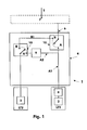
- Figure 1 shows a simplified schematic example of a block diagram of a combined multiservice line termination arrangement 1 according to a first embodiment of the present invention, for use in an access system.
- the combined line termination arrangement 1 comprises a first line termination LT1 having a first line card 2 adapted for transmitting and receiving signals in broadband transmission mode, and a second line termination LT2 having a second line card 3 adapted for transmitting and receiving signals in narrowband transmission mode.
- the first (broadband) line termination LT1 may be adapted for supporting xDSL communication.
- the corresponding first (broadband) line card 2 may comprise an xDSL baseband circuit for providing connectivity with an xDSL modem as well as a high pass filter 8; and the second (narrowband) line termination LT2 may be adapted for supporting voice telephony, for example a POTS system.
- the corresponding second (narrowband) line card 3 may comprise a voice codec circuit in order to perform the necessary digital to analog conversion, or vice-versa, in order to adapt the signal for the POTS system, as well as interface circuitry.
- the combined line termination arrangement 1 further comprises a common interface device 4 which is coupled, through separate coupling paths, to the first line termination LT1 and second line termination LT2.
- the common interface device 4 is further connected, through the common port 6 to the main subscriber line 5, for example through intermediate connection from the common interface device 4 to a main distribution frame 7 and from the latter to the main subscriber line 5.
- the common interface device 4 comprises a low pass filter 9 and a first switching means 10, such as for example a relay or equivalent, for providing switching combinations as will be described in further detail below.
- the low pass filter 9 is adapted for allowing the passage of relatively low frequencies and for blocking frequencies which are in higher ranges. Typical values for the low frequencies are frequencies below 8 KHz.
- Line termination LT1 further comprises a high pass filter 8 in order to block the low frequency signals.
- the high pass filter 8 may be selected to block frequencies below 8 KHz.
- Both filters 8 and 9 are bi-directional, namely they are capable of performing filtering operation in one direction of transmission or the other.
- switching means is provided in the common interface device 4. As shown in figure 1, a first switching means 10 is placed in an interconnecting position with respect to the common port 6, first line termination LT1 and second line termination LT2, through low pass filter 9.
- the common port 6 When the first switching means 10 is placed in position A, the common port 6 is directly connected to the first line termination LT1 through the coupling path A1 and is further connected by means of the coupling path A2 to the second line termination LT2 through the low pass filter 9.
- line termination 1 having the line card 2 transmits broadband signals to the common interface device 4 through the high pass filter 8.
- the high pass filter allows a substantially complete passage of the signal through, which is then output from the common port 6.
- Low pass filter 9 blocks the passage of the broadband signal towards the line termination LT2.
- the line termination LT2 transmits narrowband signals to the common interface device 4. These signals pass through the low pass filter 9 which allows a substantially complete passage of the narrowband signal which is then output at the common port 6. High pass filter 8 blocks the passage of the narrowband signal towards the line termination LT1.
- a combined narrowband and broadband signal input at common port 6 in directed, through the coupling path A1, towards the first lines termination LT1 where the low frequency part of the combined signal is blocked at the high pass filter 8 and the high frequency signal is allowed to pass towards the broadband line card 2.
- the combined signal input at common port 6 also is fed, through the coupling path A2, to the low pass filter 9 which blocks the high frequency signals and allows the passage of the low frequency signals towards the second line termination LT2 and thus towards the narrowband line card 3.
- the broadband service provided by the first line termination LT1 needs to be interrupted, for example because the existing broadband service needs to be replaced by a service based on a newly developed broadband technology; or where there is a need to provide connectivity with an external broadband equipment to the subscriber line, while maintaining unchanged the narrowband service provision from the line termination LT2.
- the switching means 10 may be placed in position B, where the first line card LT1 is disconnected from the common port 6 and the common interface device 4 only operates with narrowband services through the coupling path B1.
- the low pass filter 9 serves for blocking any incoming high frequency signal while the broadband service is delivered or received from an external system (not shown).
- FIG. 2 shows a further embodiment of the present invention wherein a second switching means 11 is used.
- a second switching means 11 is used.
- features similar to those of figure 1 are given the same reference numerals.
- An example of a situation where a second switching means may be necessary is where there is a need to provide a smooth migration from old equipment (e.g. local exchanges) to the new equipment.
- old equipment e.g. local exchanges
- the old local exchange subscriber line is connected to connection port 12 of the common interface device 4 through connection point C of the second switching means 11.
- Broadband service from the first line termination LT1 is activated or deactivated, based on the specific requirements of each application, by changing the position of switching means 10 as previously described in relation to figure 1.
- the operation can be performed by a simple change in the position of the second switching means 11 from position C to position D without a need to visit the respective site.
- connectivity is provided through connection port 13 towards the newly connected line termination LT2 provides narrowband service using the narrowband line card 3 as previously described in relation to figure 1.
- the present invention provides an efficient solution for combining signals of different type for transmission and separating signals of different type combined in one into separate signals, using separate line cards that operate independently from each other.
- connection and disconnection may be commanded by any known network management procedure from a convenient point of the network which could be at a distance, without the need of on site visits by a technician.
- the proposed invention provides important advantages, among which the following are noted:
Priority Applications (7)
| Application Number | Priority Date | Filing Date | Title |
|---|---|---|---|
| EP05300911A EP1786192A1 (de) | 2005-11-10 | 2005-11-10 | Leitungsabschlussanordnung mit kombinierten schmal- und breitbandigen Diensten |
| EP06300137A EP1786193A1 (de) | 2005-11-10 | 2006-02-14 | Leitungsabschlussanordnung mit kombinierten schmal- und breitbandigen Diensten |
| US11/557,967 US8259754B2 (en) | 2005-11-10 | 2006-11-08 | Line termination arrangement with combined broadband and narrowband services |
| US12/093,205 US8718041B2 (en) | 2005-11-10 | 2006-11-10 | Line termination arrangement with combined broadband and narrowband services |
| CN2006101445328A CN1964364B (zh) | 2005-11-10 | 2006-11-10 | 具有宽带和窄带组合业务的线路终端配置 |
| PCT/EP2006/068365 WO2007054569A1 (en) | 2005-11-10 | 2006-11-10 | Line termination arrangement with combined broadband and narrowband services |
| CN2006800462803A CN101326804B (zh) | 2005-11-10 | 2006-11-10 | 具有组合的宽带和窄带服务的线路终端设备 |
Applications Claiming Priority (1)
| Application Number | Priority Date | Filing Date | Title |
|---|---|---|---|
| EP05300911A EP1786192A1 (de) | 2005-11-10 | 2005-11-10 | Leitungsabschlussanordnung mit kombinierten schmal- und breitbandigen Diensten |
Publications (1)
| Publication Number | Publication Date |
|---|---|
| EP1786192A1 true EP1786192A1 (de) | 2007-05-16 |
Family
ID=36091327
Family Applications (2)
| Application Number | Title | Priority Date | Filing Date |
|---|---|---|---|
| EP05300911A Withdrawn EP1786192A1 (de) | 2005-11-10 | 2005-11-10 | Leitungsabschlussanordnung mit kombinierten schmal- und breitbandigen Diensten |
| EP06300137A Withdrawn EP1786193A1 (de) | 2005-11-10 | 2006-02-14 | Leitungsabschlussanordnung mit kombinierten schmal- und breitbandigen Diensten |
Family Applications After (1)
| Application Number | Title | Priority Date | Filing Date |
|---|---|---|---|
| EP06300137A Withdrawn EP1786193A1 (de) | 2005-11-10 | 2006-02-14 | Leitungsabschlussanordnung mit kombinierten schmal- und breitbandigen Diensten |
Country Status (4)
| Country | Link |
|---|---|
| US (2) | US8259754B2 (de) |
| EP (2) | EP1786192A1 (de) |
| CN (2) | CN101326804B (de) |
| WO (1) | WO2007054569A1 (de) |
Families Citing this family (6)
| Publication number | Priority date | Publication date | Assignee | Title |
|---|---|---|---|---|
| EP1786192A1 (de) * | 2005-11-10 | 2007-05-16 | Alcatel Lucent | Leitungsabschlussanordnung mit kombinierten schmal- und breitbandigen Diensten |
| US8576877B1 (en) | 2008-03-27 | 2013-11-05 | Centurylink Intellectual Property Llc | System and method of providing a broadband digital loop carrier cabinet |
| CN102045152B (zh) * | 2009-10-26 | 2015-03-11 | 宏正自动科技股份有限公司 | 以单一传输媒介达成全双工传输的通讯系统及其方法 |
| US8356678B2 (en) * | 2010-10-29 | 2013-01-22 | Racional Energy & Environment Company | Oil recovery method and apparatus |
| CN108616670B (zh) * | 2016-12-13 | 2021-01-19 | 海能达通信股份有限公司 | 一种宽窄带通信设备及方法 |
| CN116455691A (zh) * | 2022-01-06 | 2023-07-18 | 华为技术有限公司 | 一种通信装置及系统 |
Citations (4)
| Publication number | Priority date | Publication date | Assignee | Title |
|---|---|---|---|---|
| US6259676B1 (en) * | 1998-06-17 | 2001-07-10 | Nokia Telecommunications Oy | Upgrading of subscriber connection |
| US6295343B1 (en) | 1999-07-13 | 2001-09-25 | Catena Networks, Inc. | Method and apparatus for combining voice line card and xDSL line card functions |
| EP1175077A2 (de) | 2000-07-17 | 2002-01-23 | Lucent Technologies Inc. | Eine DSL-kompatible Teilnehmeranschlusskarte für analoge Teilnehmeranschlussleitungen |
| US20050231882A1 (en) * | 2002-09-11 | 2005-10-20 | Jean Schmitt | Device for controlling an xdsl communication line |
Family Cites Families (17)
| Publication number | Priority date | Publication date | Assignee | Title |
|---|---|---|---|---|
| US6219409B1 (en) * | 1998-02-27 | 2001-04-17 | Sharegate, Inc. | Premises gateway and premises network interfaces for accessing subscriber premises equipment and communication networks using ring suppression |
| WO2000019767A2 (de) * | 1998-09-30 | 2000-04-06 | Infineon Technologies Ag | Leitungsabschlussvorrichtung für eine teilnehmeranschlussleitung |
| US6937719B2 (en) * | 1999-02-15 | 2005-08-30 | Nokia Networks Oy | Multiplexing and demultiplexing of narrowband and broadband services in a transmission connection |
| US6567519B1 (en) * | 1999-05-28 | 2003-05-20 | Cisco Technology, Inc. | System and method for processing an input signal communicated on a telephone line |
| US6532279B1 (en) * | 1999-06-11 | 2003-03-11 | David D. Goodman | High-speed data communication over a residential telephone wiring network |
| US7088704B1 (en) * | 1999-12-10 | 2006-08-08 | Lucent Technologies Inc. | Transporting voice telephony and data via a single ATM transport link |
| EP1245107A4 (de) * | 2000-01-03 | 2008-05-21 | Rit Techn Ltd | Vorrichtung und verfahren zum testen von gemeinsamen leitungen |
| US6826278B2 (en) * | 2000-05-15 | 2004-11-30 | Centillium Communications, Inc. | Central office interface techniques for digital subscriber lines |
| US6434221B1 (en) | 2000-05-17 | 2002-08-13 | Sunrise Telecom, Inc. | Digital subscriber line access and network testing multiplexer |
| US6594343B1 (en) * | 2000-10-24 | 2003-07-15 | Turnstone Systems, Inc. | Splitter bypass architecture for testing multiple ports |
| ATE316294T1 (de) * | 2001-02-27 | 2006-02-15 | Mehrband-transformationsstufe für eine mehrband- hf-umschaltvorrichtung | |
| US6535581B2 (en) * | 2001-05-31 | 2003-03-18 | Mphase Technologies | Bypass for telephone system splitter |
| US6917683B2 (en) | 2002-11-04 | 2005-07-12 | Mphase Technologies, Inc. | Signal splitter with test relays on auxiliary circuit board and system using same |
| DE602004012277T2 (de) * | 2003-07-12 | 2009-03-12 | Huawei Technologies Co., Ltd., Shenzhen | Benutzeranschluss-Testvorrichtung und Breitband- und Schmalband-Kommunikationssystem |
| EP1786192A1 (de) * | 2005-11-10 | 2007-05-16 | Alcatel Lucent | Leitungsabschlussanordnung mit kombinierten schmal- und breitbandigen Diensten |
| US7482853B2 (en) * | 2005-12-14 | 2009-01-27 | Intersil Americas Inc. | Method and apparatus for switching audio and data signals through a single terminal |
| US7657023B2 (en) * | 2007-06-08 | 2010-02-02 | At&T Intellectual Property I, L.P. | Splitter wall plates for digital subscriber line (DSL) communication systems and methods to use the same |
-
2005
- 2005-11-10 EP EP05300911A patent/EP1786192A1/de not_active Withdrawn
-
2006
- 2006-02-14 EP EP06300137A patent/EP1786193A1/de not_active Withdrawn
- 2006-11-08 US US11/557,967 patent/US8259754B2/en active Active
- 2006-11-10 CN CN2006800462803A patent/CN101326804B/zh not_active Expired - Fee Related
- 2006-11-10 CN CN2006101445328A patent/CN1964364B/zh not_active Expired - Fee Related
- 2006-11-10 WO PCT/EP2006/068365 patent/WO2007054569A1/en active Application Filing
- 2006-11-10 US US12/093,205 patent/US8718041B2/en not_active Expired - Fee Related
Patent Citations (4)
| Publication number | Priority date | Publication date | Assignee | Title |
|---|---|---|---|---|
| US6259676B1 (en) * | 1998-06-17 | 2001-07-10 | Nokia Telecommunications Oy | Upgrading of subscriber connection |
| US6295343B1 (en) | 1999-07-13 | 2001-09-25 | Catena Networks, Inc. | Method and apparatus for combining voice line card and xDSL line card functions |
| EP1175077A2 (de) | 2000-07-17 | 2002-01-23 | Lucent Technologies Inc. | Eine DSL-kompatible Teilnehmeranschlusskarte für analoge Teilnehmeranschlussleitungen |
| US20050231882A1 (en) * | 2002-09-11 | 2005-10-20 | Jean Schmitt | Device for controlling an xdsl communication line |
Also Published As
| Publication number | Publication date |
|---|---|
| EP1786193A1 (de) | 2007-05-16 |
| US8718041B2 (en) | 2014-05-06 |
| US20070147408A1 (en) | 2007-06-28 |
| CN1964364A (zh) | 2007-05-16 |
| CN1964364B (zh) | 2011-09-14 |
| CN101326804A (zh) | 2008-12-17 |
| CN101326804B (zh) | 2011-12-28 |
| WO2007054569A1 (en) | 2007-05-18 |
| US20090135808A1 (en) | 2009-05-28 |
| US8259754B2 (en) | 2012-09-04 |
Similar Documents
| Publication | Publication Date | Title |
|---|---|---|
| US6005873A (en) | Apparatus and method for concurrent voice and data transmission | |
| US6035029A (en) | System and method for subscriber line service control | |
| US6470074B2 (en) | System and method for providing data and voice services on a shared line | |
| US6687374B2 (en) | Multi-service network interface for FDM communications systems | |
| US8259754B2 (en) | Line termination arrangement with combined broadband and narrowband services | |
| KR20030013388A (ko) | 단일 전화 회선 상의 전화 통신 시스템 | |
| US6072793A (en) | Electronically controlled main distributing frame | |
| US6898280B1 (en) | Line card and method for supporting pots, asymmetric DSL and symmetric DSL services | |
| CA2348286C (en) | A dsl-compatible pots line card | |
| EP2022221B1 (de) | Hybrid-ip/atm-dslam und verfahren zum bereitstellen von hybrid-ip/atm-dsl-zugangsmultiplexen | |
| EP1858196A1 (de) | Vereinigte breit- und schmalband-baugruppe für eine integrierte zugangsvorrichtung | |
| US7065072B1 (en) | Method and system for providing telecommunication services by a plurality of service providers | |
| EP2165519B1 (de) | Anordnung und verfahren bezüglich teilnehmeranschlussverbindungen | |
| US20020027900A1 (en) | System and method for programmable spectrum management | |
| US20020141428A1 (en) | Line card and method for supporting a plurality of telecommunication services | |
| US20020186835A1 (en) | Multi-service network interface method for frequency-division multiplexed communications systems | |
| EP2131563B1 (de) | Leitungsabschlussplatte mit mehreren xDSL-Leitungshochpassfiltern | |
| EP1175076A2 (de) | Vorrichtung und Verfahren zur Bereitstellung von POTS Notdiensten in einem Netzwerk ohne integrierte POTS Notdienstverbindungen | |
| EP1643797A1 (de) | Verfahren und Vorrichtung zur Konfiguration einer automatischen Crossconnect-Einrichtung in einem Fernverdrahtungssystem | |
| WO2006079984A1 (en) | Method and system for provisioning broadband service |
Legal Events
| Date | Code | Title | Description |
|---|---|---|---|
| PUAI | Public reference made under article 153(3) epc to a published international application that has entered the european phase |
Free format text: ORIGINAL CODE: 0009012 |
|
| AK | Designated contracting states |
Kind code of ref document: A1 Designated state(s): AT BE BG CH CY CZ DE DK EE ES FI FR GB GR HU IE IS IT LI LT LU LV MC NL PL PT RO SE SI SK TR |
|
| AX | Request for extension of the european patent |
Extension state: AL BA HR MK YU |
|
| 17P | Request for examination filed |
Effective date: 20071116 |
|
| 17Q | First examination report despatched |
Effective date: 20071219 |
|
| AKX | Designation fees paid |
Designated state(s): AT BE BG CH CY CZ DE DK EE ES FI FR GB GR HU IE IS IT LI LT LU LV MC NL PL PT RO SE SI SK TR |
|
| RAP1 | Party data changed (applicant data changed or rights of an application transferred) |
Owner name: ALCATEL LUCENT |
|
| 111Z | Information provided on other rights and legal means of execution |
Free format text: AT BE BG CH CY CZ DE DK EE ES FI FR GB GR HU IE IS IT LI LT LU LV MC NL PL PT RO SE SI SK TR Effective date: 20130410 |
|
| RAP1 | Party data changed (applicant data changed or rights of an application transferred) |
Owner name: ALCATEL LUCENT |
|
| D11X | Information provided on other rights and legal means of execution (deleted) | ||
| GRAP | Despatch of communication of intention to grant a patent |
Free format text: ORIGINAL CODE: EPIDOSNIGR1 |
|
| STAA | Information on the status of an ep patent application or granted ep patent |
Free format text: STATUS: GRANT OF PATENT IS INTENDED |
|
| INTG | Intention to grant announced |
Effective date: 20171108 |
|
| RAP1 | Party data changed (applicant data changed or rights of an application transferred) |
Owner name: ALCATEL LUCENT |
|
| RAP1 | Party data changed (applicant data changed or rights of an application transferred) |
Owner name: PROVENANCE ASSET GROUP LLC |
|
| STAA | Information on the status of an ep patent application or granted ep patent |
Free format text: STATUS: THE APPLICATION IS DEEMED TO BE WITHDRAWN |
|
| 18D | Application deemed to be withdrawn |
Effective date: 20180320 |