EP1786107A1 - Kapazitiver Berührungsschalter - Google Patents
Kapazitiver Berührungsschalter Download PDFInfo
- Publication number
- EP1786107A1 EP1786107A1 EP06022980A EP06022980A EP1786107A1 EP 1786107 A1 EP1786107 A1 EP 1786107A1 EP 06022980 A EP06022980 A EP 06022980A EP 06022980 A EP06022980 A EP 06022980A EP 1786107 A1 EP1786107 A1 EP 1786107A1
- Authority
- EP
- European Patent Office
- Prior art keywords
- touch switch
- circuit board
- capacitive touch
- sensor element
- printed circuit
- Prior art date
- Legal status (The legal status is an assumption and is not a legal conclusion. Google has not performed a legal analysis and makes no representation as to the accuracy of the status listed.)
- Granted
Links
- 230000006835 compression Effects 0.000 claims abstract description 43
- 238000007906 compression Methods 0.000 claims abstract description 43
- 239000004020 conductor Substances 0.000 claims abstract description 13
- 229910000679 solder Inorganic materials 0.000 claims description 4
- 230000001419 dependent effect Effects 0.000 claims description 2
- 230000000875 corresponding effect Effects 0.000 description 10
- 238000000034 method Methods 0.000 description 3
- 230000006978 adaptation Effects 0.000 description 2
- 230000000694 effects Effects 0.000 description 2
- 238000011156 evaluation Methods 0.000 description 2
- 239000002241 glass-ceramic Substances 0.000 description 2
- 230000008569 process Effects 0.000 description 2
- 238000005406 washing Methods 0.000 description 2
- 230000002411 adverse Effects 0.000 description 1
- 230000032683 aging Effects 0.000 description 1
- 230000008859 change Effects 0.000 description 1
- 238000010276 construction Methods 0.000 description 1
- 238000005516 engineering process Methods 0.000 description 1
- 239000006260 foam Substances 0.000 description 1
- 239000011888 foil Substances 0.000 description 1
- 238000009434 installation Methods 0.000 description 1
- 239000000463 material Substances 0.000 description 1
- 238000001465 metallisation Methods 0.000 description 1
- 238000012986 modification Methods 0.000 description 1
- 230000004048 modification Effects 0.000 description 1
- 238000005476 soldering Methods 0.000 description 1
Images


Classifications
-
- H—ELECTRICITY
- H01—ELECTRIC ELEMENTS
- H01H—ELECTRIC SWITCHES; RELAYS; SELECTORS; EMERGENCY PROTECTIVE DEVICES
- H01H13/00—Switches having rectilinearly-movable operating part or parts adapted for pushing or pulling in one direction only, e.g. push-button switch
- H01H13/02—Details
-
- H—ELECTRICITY
- H03—ELECTRONIC CIRCUITRY
- H03K—PULSE TECHNIQUE
- H03K17/00—Electronic switching or gating, i.e. not by contact-making and –breaking
- H03K17/94—Electronic switching or gating, i.e. not by contact-making and –breaking characterised by the way in which the control signals are generated
- H03K17/96—Touch switches
- H03K17/962—Capacitive touch switches
-
- D—TEXTILES; PAPER
- D06—TREATMENT OF TEXTILES OR THE LIKE; LAUNDERING; FLEXIBLE MATERIALS NOT OTHERWISE PROVIDED FOR
- D06F—LAUNDERING, DRYING, IRONING, PRESSING OR FOLDING TEXTILE ARTICLES
- D06F34/00—Details of control systems for washing machines, washer-dryers or laundry dryers
- D06F34/28—Arrangements for program selection, e.g. control panels therefor; Arrangements for indicating program parameters, e.g. the selected program or its progress
- D06F34/32—Arrangements for program selection, e.g. control panels therefor; Arrangements for indicating program parameters, e.g. the selected program or its progress characterised by graphical features, e.g. touchscreens
-
- H—ELECTRICITY
- H01—ELECTRIC ELEMENTS
- H01H—ELECTRIC SWITCHES; RELAYS; SELECTORS; EMERGENCY PROTECTIVE DEVICES
- H01H13/00—Switches having rectilinearly-movable operating part or parts adapted for pushing or pulling in one direction only, e.g. push-button switch
- H01H13/02—Details
- H01H13/12—Movable parts; Contacts mounted thereon
- H01H13/14—Operating parts, e.g. push-button
-
- H—ELECTRICITY
- H01—ELECTRIC ELEMENTS
- H01H—ELECTRIC SWITCHES; RELAYS; SELECTORS; EMERGENCY PROTECTIVE DEVICES
- H01H13/00—Switches having rectilinearly-movable operating part or parts adapted for pushing or pulling in one direction only, e.g. push-button switch
- H01H13/02—Details
- H01H13/26—Snap-action arrangements depending upon deformation of elastic members
- H01H13/28—Snap-action arrangements depending upon deformation of elastic members using compression or extension of coil springs
-
- H—ELECTRICITY
- H03—ELECTRONIC CIRCUITRY
- H03K—PULSE TECHNIQUE
- H03K2217/00—Indexing scheme related to electronic switching or gating, i.e. not by contact-making or -breaking covered by H03K17/00
- H03K2217/94—Indexing scheme related to electronic switching or gating, i.e. not by contact-making or -breaking covered by H03K17/00 characterised by the way in which the control signal is generated
- H03K2217/96—Touch switches
- H03K2217/9607—Capacitive touch switches
- H03K2217/960755—Constructional details of capacitive touch and proximity switches
-
- H—ELECTRICITY
- H03—ELECTRONIC CIRCUITRY
- H03K—PULSE TECHNIQUE
- H03K2217/00—Indexing scheme related to electronic switching or gating, i.e. not by contact-making or -breaking covered by H03K17/00
- H03K2217/94—Indexing scheme related to electronic switching or gating, i.e. not by contact-making or -breaking covered by H03K17/00 characterised by the way in which the control signal is generated
- H03K2217/96—Touch switches
- H03K2217/9607—Capacitive touch switches
- H03K2217/960755—Constructional details of capacitive touch and proximity switches
- H03K2217/96076—Constructional details of capacitive touch and proximity switches with spring electrode
-
- H—ELECTRICITY
- H03—ELECTRONIC CIRCUITRY
- H03K—PULSE TECHNIQUE
- H03K2217/00—Indexing scheme related to electronic switching or gating, i.e. not by contact-making or -breaking covered by H03K17/00
- H03K2217/94—Indexing scheme related to electronic switching or gating, i.e. not by contact-making or -breaking covered by H03K17/00 characterised by the way in which the control signal is generated
- H03K2217/96—Touch switches
- H03K2217/9607—Capacitive touch switches
- H03K2217/960755—Constructional details of capacitive touch and proximity switches
- H03K2217/96077—Constructional details of capacitive touch and proximity switches comprising an electrode which is floating
Definitions
- the present invention relates to a capacitive touch switch according to the Oberbebgriff of claim 1.
- touch switches are increasingly used that trigger a certain switching by a simple touch by a user.
- a capacitive touch switch a capacitive sensor element, together with a user's finger, forms a capacitance via a touch pad acting as a dielectric, which is variable according to the operation of the touch switch, ie touching or not touching a touch pad associated with the capacitive sensor element.
- the change in the capacitance of the capacitive sensor element by a contact by the user has a corresponding effect on an output signal of the sensor circuit, which is evaluated by a connected evaluation circuit accordingly as an operation of the capacitive touch switch.
- Such a capacitive touch switch is for example from DE 32 45 803 A1 known.
- the DE 20 2005 002 157 U1 a capacitive sensor element for a touch switch of the type specified above, which is formed of an electrically conductive compression spring, the contact pad facing the end is extended.
- the compression spring is mechanically and electrically connected to a circuit board, for example by means of soldering.
- a capacitive sensor element ensures good contact between the sensor element and the touchpad and, on the other hand, offers an extended sensitive area. adversely However, this capacitive sensor element is its complicated shape due to the extension area.
- the U.S. Patent No. 5,917,165 describes a sensor element for a capacitive touch switch, which is formed of an electrically conductive, elastic foam, plastic or rubber body.
- a sensor element is characterized by its simple structure and its simple installation and also ensures good electrical contact both to the circuit board and to the touchpad.
- the capacitive touch switch has a touch panel with a top and a bottom; a circuit board disposed at a distance below the bottom of the touch panel; and a capacitive sensing element disposed between the underside of the touch pad and the circuit board and in electrical contact with the circuit board.
- the capacitive sensor element in turn has a compression spring made of an electrically conductive material and a contact element made of an electrically conductive material, which is arranged on the contact pad facing side of the compression spring and electrically in contact with the compression spring, on.
- the contact element can be variably adapted to both the shape and nature of the touch pad and the shape and size of the sensitive area presented to the user. Due to the two-part construction of the sensor element such an adaptation is easily possible without a single component is overloaded with features or functions.
- the contact element can also form a relatively large sensitive area without the need for metallization of the touch panel would be necessary.
- the compression spring which is supported against the circuit board and the contact element, ensures a reliable contact between the contact element of the sensor element and the underside of the touch panel, whereby the operability of the capacitive touch switch is improved even with temperature changes, aging processes of the components, tolerances and position inaccuracies of the components and the like.
- the capacitive touch switch further comprises a central retaining pin which extends through the sensor element substantially over its entire height. On this retaining pin, the compression spring and the contact element can be pushed or plugged and so easily positioned between the circuit board and touch pad.
- the retaining pin can be provided at its end facing the circuit board with a locking device for mechanical connection to the circuit board.
- the retaining pin may also be formed integrally with the touch panel.
- the capacitive sensor element further comprises, on its side facing the printed circuit board, a further contact element for making electrical contact with the printed circuit board.
- This further contact element may be provided with a latching device for mechanical connection to the printed circuit board. Further, this further contact element and the compression spring may be connected to each other by a solder joint.
- a further contact element for electrical contacting with the compression spring is provided on the circuit board, against which the compression spring is supported.
- the contact element and the compression spring of the sensor element are connected to one another by a solder connection.
- the retaining pin is formed as a light guide, and on the circuit board is at a central position of the Sensor element arranged a light-emitting element such as an LED, so that the touch panel for the user can be backlit.
- a luminous element is arranged on the circuit board at a central position of the sensor element, to which a central light-guiding element can also be assigned, which extends through the sensor element substantially over its entire height.
- the touch switch further comprises at least one luminous element next to the capacitive sensor element between the circuit board and the touch panel to backlight the touch panel over a large area.
- the touch panel may be provided on its upper side with a film which is metallized on its rear side facing the touch panel in the region of the contact element of the capacitive sensor element.
- a film which is metallized on its rear side facing the touch panel in the region of the contact element of the capacitive sensor element.
- the film is advantageously a metallized color imprint usable.
- the touch panel may be provided on its underside with a film which is metallized on its rear side facing the touch panel in the region of the contact element of the capacitive sensor element.
- a film which is metallized on its rear side facing the touch panel in the region of the contact element of the capacitive sensor element.
- the film or color print arranged on the underside of the touch panel is in contact with another panel, which may consist of a different material than the touch panel.
- Fig. 1 shows a detail of a control panel of an electrical device, in particular a household electrical appliance (stove, hob, microwave oven, dishwasher, washing machine and the like) schematically in perspective view.
- a household electrical appliance such as, hob, microwave oven, dishwasher, washing machine and the like
- a touch pad such as a plastic plate or a glass ceramic plate of a cooktop having a top 12 and a bottom 14.
- a film 16 is applied, for example, by means of IMD or IML technology, which, for example, provides a (preferably metallised) color imprint to identify the different sensitive areas 18 of the individual touch switches is.
- IMD ink-sensitive device
- IML ink-sensitive layer
- the underside 14 of the touch pad 10 it is also possible on the underside 14 of the touch pad 10 to have a film 16 (see also FIG. 5) or a metallized color imprint, for example by means of IMD. or IML technique for identifying the various sensitive areas 18 of the individual touch switches.
- a printed circuit board 20 is arranged, which is equipped with various electrical components (not shown) and in particular contains a sensor circuit and an evaluation circuit for the various capacitive touch switches.
- FIG. 1 a total of three different capacitive touch switches 22 are illustrated according to a first, a second and a third embodiment with correspondingly different sensor elements, which are explained below with reference to FIGS. 2 to 4 in more detail.
- the capacitive touch switch 22 according to the first exemplary embodiment shown in FIG. 2 (without touch pad 10 and printed circuit board 20) corresponds to the embodiment on the right in FIG. 1.
- the capacitive sensor element of this touch switch 22 essentially consists of a compression spring 24 made of an electrically conductive material, a contact element 26 which is arranged on the side of the compression spring 24 facing the contact pad 10 (at the top in FIG. 2), made of an electrically conductive material, and a further contact element 28, which is arranged on the side facing the printed circuit board 20 of the compression spring 24 (bottom in Fig. 2), made of an electrically conductive material.
- the contact element 26 and the further contact element 28 are in each case electrically conductively in contact with the compression spring 24, which is supported against these two contact elements 26, 28.
- the capacitive touch switch 22 of this embodiment further includes a central retaining pin 30, for example, made of plastic, which extends substantially over the entire height of the sensor element and at its end facing the circuit board 20 (bottom in Fig. 2), a locking device 32 is provided or integral is formed with this.
- the latching device 32 is formed, for example in the form of an enlarged tip with a central recess, so that the latching device 32 can be pressed by a corresponding mounting hole in the circuit board 20 and clamped there, as illustrated in Fig. 1.
- the central holding pin 30 serves to position the sensor element of the capacitive touch switch 22 on the printed circuit board 20.
- the sensor element consisting of compression spring 24, contact element 26 and further contact element 28 placed on the retaining pin 30 and then mounted this preassembled module on the circuit board 20 be, or the retaining pin 30 may first be mounted on the circuit board 20 and then equipped with the sensor element consisting of compression spring 24, contact element 26 and further contact element 28.
- the capacitive touch switch 22 allows a simple assembly process.
- the two contact elements 26 and 28 are shown in Fig. 2 each disk-shaped. However, the present invention is not limited to any particular shape and size of these contact elements 26, 28;
- the contact element 26 to the touch panel 10 may be adapted in shape and size to the desired sensitive area 18 and in its shape and nature of the bottom 14 of the touch pad 10.
- the contour of the contact element 26 may be circular, elliptical, square, rectangular, kidney-shaped, etc.
- the corresponding sensitive area 18 of the capacitive touch switch 22 is indicated to the user by a color imprint on the film 16, for example. Even raised or recessed areas of the underside 16 of the touchpad 10 can be easily adapted by a corresponding contact element 26.
- the sensor element is composed of compression spring 24, contact element 26 and further contact element 28 of the capacitive touch switch 22 between the bottom 14 of the touch pad 10 and the circuit board 20 and arranged by the retaining pin 30 in fixed in position.
- the compression spring 24 presses on the one hand the contact element 26 against the bottom 14 of the touch pad 10 and on the other hand, the further contact element 28 against a corresponding electrical contact 40 on the circuit board 20. This is regardless of temperature fluctuations, component tolerances, position inaccuracies and the like always a sufficiently good contact of the sensor element ensures that the operability of the capacitive touch switch 22 is ensured.
- the compression spring 24, the contact element 26 and the further contact element 28 are loosely placed on the retaining pin 30, it is also possible, the compression spring 24 and the contact element 26 and / or the compression spring 24 and the further contact element 28th electrically and mechanically connect to each other by means of a solder joint.
- the sensor element of this capacitive touch switch 22 consists of a compression spring 24 made of an electrically conductive material, a contact element 26 which is provided on the contact pad 10 side facing the compression spring 24, an electrically conductive material, and a another contact element 28 which is provided on the printed circuit board 20 side facing the compression spring 24, made of an electrically conductive material.
- the further contact element 28 also has a latching device 34, for example in the form of struts, which can be inserted and clamped through corresponding mounting holes in the circuit board 20, as illustrated in Fig. 1 center.
- the capacitive touch switch 22 in this case additionally a luminous element 36, for example in the form of a light emitting diode (LED), which is mounted with respect to the sensor element 24-28 centered on the circuit board 20.
- a luminous element 36 for example in the form of a light emitting diode (LED)
- the sensitive area 18 of this capacitive touch switch 22 can be backlit in a simple way for the user.
- the capacitive touch switch 22 further comprises a central light-guiding element 38 extending through the sensor element 24-28 substantially over its entire height and optionally up to the bottom 14 of the touchpad 10 extends into it.
- a third embodiment of the capacitive touch scraper 22 will now be explained in greater detail on the basis of FIG. 4 and FIG. 1 on the left.
- the capacitive touch switch 22 of Fig. 4 has a sensor element consisting of a compression spring 24 made of an electrically conductive material and a contact element 26 made of an electrically conductive material, which is arranged on the contact pad 10 side facing the compression spring 24.
- the sensor element of this capacitive touch switch 22 no further contact element 28 on the printed circuit board 20 facing side of the compression spring 24.
- the circuit board 20 itself is provided with a further contact element 40 in the form of an electrical contact surface, as shown in Fig. 1 on the left.
- the compression spring 24 is supported here against the contact element 26 and against the further contact element 40 of the circuit board 20 from.
- a central retaining pin 42 for example made of plastic or glass ceramic, which is formed integrally with the touch panel 10 and extends over the entire height of the sensor element 24-26 through a corresponding mounting hole in the printed circuit board 20 extends to position the sensor element 24-26 exactly between the circuit board 20 and the touchpad 10 can.
- a locking device analogous to the first embodiment is not provided here on the central retaining pin 42, but may optionally also be present.
- the capacitive touch switch 22 includes a sensor element according to FIG. 4 with a compression spring 24 and a contact element 26, a further contact element 40 on the printed circuit board 20 according to FIG. 4 and a central holding pin 30 according to FIG. 2.
- central retaining pin 42 as a light-guiding element and to arrange on the printed circuit board 20 at the corresponding position a lighting element, for example in the form of an LED, so that the sensitive area 18 of the touch switch 22 on the touch panel 10 can be backlit for the user analogously to the above second embodiment.
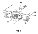
- FIG. 5 shows a schematic representation of a capacitive touch switch 22 of another embodiment.
- the touch switch 22 of Fig. 5 is constructed substantially like that of the third embodiment of Fig. 4, but the present embodiment is analogously applicable to the other described embodiments.
- lighting elements 44 are provided on the circuit board 20 on two sides consisting for example of an LED and a light guide. In this way, it is possible to illuminate the sensitive area 18 of the capacitive touch switch 22 on the touch panel 10 over a large area.
Landscapes
- Engineering & Computer Science (AREA)
- Textile Engineering (AREA)
- Switches That Are Operated By Magnetic Or Electric Fields (AREA)
- Electronic Switches (AREA)
- Push-Button Switches (AREA)
Abstract
Description
- Die vorliegende Erfindung betrifft einen kapazitiven Berührungsschalter nach dem Oberbebgriff des Anspruchs 1.
- In vielen elektrischen Geräten, insbesondere auch in Haushaltsgeräten wie Herden, Kochfeldern, Mikrowellenöfen, Spülmaschinen, Waschmaschinen und dergleichen, werden immer häufiger Berührungsschalter eingesetzt, die durch ein einfaches Berühren durch einen Benutzer einen bestimmten Schaltvorgang auslösen. Im Fall eines kapazitiven Berührungsschalters bildet ein kapazitives Sensorelement zu-, sammen mit dem Finger eines Benutzers über ein als Dielektrikum wirkendes Berührungsfeld eine Kapazität, die entsprechend dem Betätigen des Berührungsschalters, d.h. dem Berühren oder Nicht-Berühren eines dem kapazitiven Sensorelement zugeordneten Berührungsfeldes variabel ist. Die Veränderung der Kapazität des kapazitiven Sensorelements durch eine Berührung durch den Benutzer wirkt sich entsprechend auf ein Ausgangssignal der Sensorschaltung aus, was von einer angeschlossenen Auswerteschaltung entsprechend als eine Betätigung des kapazitiven Berührungsschalters ausgewertet wird. Ein derartiger kapazitiver Berührungsschalter ist zum Beispiel aus der
DE 32 45 803 A1 bekannt. - Ferner offenbart die
DE 20 2005 002 157 U1 ein kapazitives Sensorelement für einen Berührungsschalter der oben angegebenen Art, das aus einer elektrisch leitenden Druckfeder gebildet ist, deren dem Berührungsfeld zugewandtes Ende erweitert ist. Die Druckfeder ist mechanisch und elektrisch mit einer Leiterplatte zum Beispiel mittels Löten verbunden. Ein solches kapazitives Sensorelement gewährleistet einerseits einen guten Kontakt zwischen dem Sensorelement und dem Berührungsfeld und bietet andererseits einen erweiterten sensitiven Bereich. Nachteilig bei diesem kapazitiven Sensorelement ist allerdings seine komplizierte Form aufgrund des Erweiterungsbereichs. - Das
US-Patent Nr. 5,917 165 beschreibt ein Sensorelement für einen kapazitiven Berührungsschalter, der aus einem elektrisch leitfähigen, elastischen Schaumstoff-, Kunststoff- oder Gummikörper gebildet ist. Ein solches Sensorelement zeichnet sich durch seinen einfachen Aufbau und seine einfache Montage aus und gewährleistet außerdem einen guten elektrischen Kontakt sowohl zur Leiterplatte als auch zum Berührungsfeld. - Es ist eine Aufgabe der vorliegenden Erfindung, einen weiteren kapazitiven Berührungsschalter vorzusehen, der einen guten elektrischen Kontakt zum Berührungsfeld auch bei Temperaturwechseln gewährleistet und trotz seines einfachen Aufbaus variabel einsetzbar ist.
- Diese Aufgabe wird durch einen kapazitiven Berührungsschalter mit den Merkmalen des Anspruchs 1 gelöst. Vorteilhafte Ausgestaltungen und Weiterbildungen der Erfindung sind Gegenstand der abhängigen Ansprüche.
- Der kapazitive Berührungsschalter weist ein Berührungsfeld mit einer Oberseite und einer Unterseite; einer Leiterplatte, die mit einem Abstand unter der Unterseite des Berührungsfeldes angeordnet ist; und ein kapazitives Sensorelement, das zwischen der Unterseite des Berührungsfeldes und der Leiterplatte angeordnet und mit der Leiterplatte elektrisch leitend in Kontakt ist, auf. Das kapazitive Sensorelement weist seinerseits eine Druckfeder aus einem elektrisch leitenden Material und ein Kontaktelement aus einem elektrisch leitenden Material, das auf der dem Berührungsfeld zugewandten Seite der Druckfeder angeordnet und mit der Druckfeder elektrisch leitend in Kontakt ist, auf.
- Das Kontaktelement kann variabel sowohl an die Form und die Beschaffenheit des Berührungsfeldes als auch an die Form und Größe des dem Benutzer dargebotenen sensitiven Bereichs angepasst werden. Aufgrund des zweiteiligen Aufbaus des Sensorelements ist eine solche Anpassung problemlos möglich, ohne dass ein einziges Bauelement mit Merkmalen bzw. Funktionen überfrachtet wird. Das Kontaktelement kann dabei auch einen relativ großen sensitiven Bereich bilden, ohne dass hierzu Metallisierungen des Berührungsfeldes notwendig wären. Die Druckfeder, die sich gegen die Leiterplatte und das Kontaktelement abstützt, gewährleistet einen zuverlässigen Kontakt zwischen dem Kontaktelement des Sensorelements und der Unterseite des Berührungsfeldes, wodurch die Funktionsfähigkeit des kapazitiven Berührungsschalters auch bei Temperaturänderungen, Alterungsprozessen der Bauelemente, Toleranzen und Positionsungenauigkeiten der Bauelemente und der dergleichen verbessert ist.
- In einer Ausgestaltung der Erfindung weist der kapazitive Berührungsschalter ferner einen zentralen Haltestift auf, der sich durch das Sensorelement im Wesentlichen über dessen gesamte Höhe erstreckt. Auf diesen Haltestift können die Druckfeder und das Kontaktelement aufgeschoben bzw. aufgesteckt werden und so einfach zwischen Leiterplatte und Berührungsfeld positioniert werden.
- Der Haltestift kann dabei an seinem der Leiterplatte zugewandten Ende mit einer Rastvorrichtung zur mechanischen Verbindung mit der Leiterplatte versehen sein. Alternativ kann der Haltestift auch integral mit dem Berührungsfeld ausgebildet sein.
- In einer weiteren Ausgestaltung der Erfindung weist das kapazitive Sensorelement ferner auf seiner der Leiterplatte zugewandten Seite ein weiteres Kontaktelement zur elektrischen Kontaktierung mit der Leiterplatte auf.
- Dieses weitere Kontaktelement kann mit einer Rastvorrichtung zur mechanischen Verbindung mit der Leiterplatte versehen sein. Weiter können dieses weitere Kontaktelement und die Druckfeder durch eine Lötverbindung miteinander verbunden sein.
- In einer alternativen Ausgestaltung der Erfindung ist auf der Leiterplatte ein weiteres Kontaktelement zur elektrischen Kontaktierung mit der Druckfeder vorgesehen, gegen das sich die Druckfeder abstützt.
- In einer weiteren Ausgestaltung der Erfindung sind das Kontaktelement und die Druckfeder des Sensorelements durch eine Lötverbindung miteinander verbunden.
- In einer noch weiteren Ausgestaltung der Erfindung ist der Haltestift als ein Lichtleitelement ausgebildet, und auf der Leiterplatte ist an einer mittigen Position des Sensorelements ein Leuchtelement wie beispielsweise eine LED angeordnet, sodass das Berührungsfeld für den Benutzer hinterleuchtet werden kann.
- In einer alternativen Ausführungsform ohne Haltestift ist auf der Leiterplatte an einer mittigen Position des Sensorelements ein Leuchtelement angeordnet, dem ferner ein zentrales Lichtleitelement zugeordnet sein kann, das sich durch das Sensorelement im Wesentlichen über dessen gesamte Höhe erstreckt.
- In einer weiteren alternativen Ausführungsform weist der Berührungsschalter ferner wenigstens ein Leuchtelement neben dem kapazitiven Sensorelement zwischen der Leiterplatte und dem Berührungsfeld auf, um das Berührungsfeld großflächig zu hinterleuchten.
- Ferner kann das Berührungsfeld auf seiner Oberseite mit einer Folie versehen sein, die an ihrer dem Berührungsfeld zugewandten Rückseite im Bereich des Kontaktelements des kapazitiven Sensorelements metallisiert ist. Anstelle der Folie ist vorteilhafter Weise ein metallisierter Farbaufdruck verwendbar.
- In einer alternativen Ausführungsform kann das Berührungsfeld auf seiner Unterseite mit einer Folie versehen sein, die an ihrer dem Berührungsfeld zugewandten Rückseite im Bereich des Kontaktelements des kapazitiven Sensorelements metallisiert ist. Anstelle der Folie ist vorteilhafter Weise ein metallisierter Farbaufdruck verwendbar.
- In einer besonders vorteilhaften Ausführung ist die an der Unterseite des Berührungsfeldes angeordnete Folie bzw. der Farbaufdruck in Kontakt mit einer weiteren Platte, die aus einem anderen Material bestehen kann als das Berührungsfeld.
- Obige sowie weitere Merkmale und Vorteile der Erfindung werden aus der nachfolgenden Beschreibung bevorzugter, nicht-einschränkender Ausführungsbeispiele unter Bezugnahme auf die beiliegenden Zeichnungen besser verständlich. Darin zeigen:
- Fig. 1
- eine schematische Perspektivansicht eines aufgeschnittenen Bedienfeldes mit mehreren verschiedenen kapazitiven Berührungsschaltern gemäß der vorliegenden Erfindung;
- Fig. 2
- eine schematische Seitenansicht eines Sensorelements eines kapazitiven Berührungsschalters gemäß einem ersten Ausführungsbeispiel der vorliegenden Erfindung;
- Fig. 3
- eine schematische Seitenansicht eines Sensorelements eines kapazitiven Berührungsschalters gemäß einem zweiten Ausführungsbeispiel der vorliegenden Erfindung;
- Fig. 4
- eine schematische Perspektivansicht eines Sensorelements eines kapazitiven Berührungsschalters gemäß einem dritten Ausführungsbeispiel der vorliegenden Erfindung; und
- Fig. 5
- eine schematische Perspektivansicht eines aufgeschnittenen kapazitiven Berührungsschalters gemäß einem vierten Ausführungsbeispiel der vorliegenden Erfindung.
- Fig. 1 zeigt einen Ausschnitt eines Bedienfeldes eines elektrischen Geräts, insbesondere eines elektrischen Haushaltsgeräts (Herd, Kochfeld, Mikrowellenofen, Spülmaschine, Waschmaschine und dergleichen) schematisch in Perspektivansicht.
- Mit 10 ist ein Berührungsfeld wie beispielsweise eine Kunststoffplatte oder eine Glaskeramikplatte eines Kochfeldes bezeichnet, die eine Oberseite 12 und eine Unterseite 14 besitzt. Auf der Oberseite 12 des Berührungsfeldes 10 ist eine Folie 16 (siehe auch Fig. 5) zum Beispiel mittels IMD- oder IML-Technik aufgebracht, die zur Kennzeichnung der verschiedenen sensitiven Bereiche 18 der einzelnen Berührungsschalter zum Beispiel mit einem (vorzugsweise metallisierten) Farbaufdruck versehen ist. Anstelle der Folie ist auch ein metallisierter Aufdruck einsetzbar.
- Es kann aber auch auf der Unterseite 14 des Berührungsfeldes 10 eine Folie 16 (siehe auch Fig. 5) oder ein metallisierter Farbaufdruck zum Beispiel mittels IMD- oder IML-Technik zur Kennzeichnung der verschiedenen sensitiven Bereiche 18 der einzelnen Berührungsschalter aufgebracht sein.
- In einem bestimmten Abstand von der Unterseite 14 des Berührungsfeldes 10 ist eine Leiterplatte 20 angeordnet, die mit diversen elektrischen Bauelementen (nicht dargestellt) bestückt ist und insbesondere eine Sensorschaltung und eine Auswerteschaltung für die verschiedenen kapazitiven Berührungsschalter enthält.
- In der Darstellung von Fig. 1 sind insgesamt drei unterschiedliche kapazitive Berührungsschalter 22 gemäß einem ersten, einem zweiten und einem dritten Ausführungsbeispiel mit entsprechend unterschiedlichen Sensorelementen veranschaulicht, die nachfolgend anhand der Fig. 2 bis 4 im mehr Einzelheiten erläutert werden.
- Der in Fig. 2 (ohne Berührungsfeld 10 und Leiterplatte 20) dargestellte kapazitive Berührungsschalter 22 gemäß dem ersten Ausführungsbeispiel entspricht der Ausführungsform rechts in Fig. 1.
- Das kapazitive Sensorelement dieses Berührungsschalters 22 besteht im Wesentlichen aus einer Druckfeder 24 aus einem elektrisch leitenden Material, einem Kontaktelement 26, das auf der dem Berührungsfeld 10 zugewandten Seite der Druckfeder 24 (oben in Fig. 2) angeordnet ist, aus einem elektrischen leitenden Material, und einem weiteren Kontaktelement 28, das auf der der Leiterplatte 20 zugewandten Seite der Druckfeder 24 (unten in Fig. 2) angeordnet ist, aus einem elektrischen leitenden Material. Das Kontaktelement 26 und das weitere Kontaktelement 28 stehen jeweils mit der Druckfeder 24 elektrisch leitend in Kontakt, die sich gegen diese beiden Kontaktelemente 26, 28 abstützt.
- Der kapazitive Berührungsschalter 22 dieses Ausführungsbeispiels enthält ferner einen zentralen Haltestift 30 zum Beispiel aus Kunststoff, der sich im Wesentlichen über die gesamte Höhe des Sensorelements erstreckt und an dessen der Leiterplatte 20 zugewandtem Ende (unten in Fig. 2) eine Rastvorrichtung 32 vorgesehen bzw. integral mit diesem ausgebildet ist. Die Rastvorrichtung 32 ist zum Beispiel in Form einer erweiterten Spitze mit einer zentralen Ausnehmung ausgebildet, sodass die Rastvorrichtung 32 durch ein entsprechendes Montageloch in der Leiterplatte 20 gedrückt und dort festgeklemmt werden kann, wie in Fig. 1 veranschaulicht.
- Der zentrale Haltestift 30 dient der Positionierung des Sensorelements des kapazitiven Berührungsschalters 22 auf der Leiterplatte 20. Zur Montage kann entweder das Sensorelement bestehend aus Druckfeder 24, Kontaktelement 26 und weiterem Kontaktelement 28 auf den Haltestift 30 gesetzt und dann diese vormontierte Baugruppe auf der Leiterplatte 20 montiert werden, oder der Haltestift 30 kann zunächst auf der Leiterplatte 20 montiert und dann mit dem Sensorelement bestehend aus Druckfeder 24, Kontaktelement 26 und weiterem Kontaktelement 28 bestückt werden. In jedem Fall ermöglicht der kapazitive Berührungsschalter 22 einen einfachen Montageprozess.
- Die beiden Kontaktelemente 26 und 28 sind in Fig. 2 jeweils scheibenförmig dargestellt. Die vorliegende Erfindung ist aber auf keine spezielle Form und Größe dieser Kontaktelemente 26, 28 eingeschränkt; insbesondere das Kontaktelement 26 zum Berührungsfeld 10 kann in seiner Form und Größe dem gewünschten sensitiven Bereich 18 und in seiner Form und Beschaffenheit der Unterseite 14 des Berührungsfeldes 10 angepasst sein. So kann die Kontur des Kontaktelements 26 zum Beispiel kreisförmig, elliptisch, quadratisch, rechteckig, nierenförmig, usw. sein. Der entsprechende sensitive Bereich 18 des kapazitiven Berührungsschalters 22 wird, wie bereits oben erwähnt, dem Benutzer zum Beispiel durch einen Farbaufdruck auf der Folie 16 angezeigt. Selbst erhabene oder vertiefte Bereiche der Unterseite 16 des Berührungsfeldes 10 können durch ein entsprechendes Kontaktelement 26 problemlos adaptiert werden.
- Im montierten Zustand, wie er in Fig. 1 rechts gezeigt ist, ist das Sensorelement bestehend aus Druckfeder 24, Kontaktelement 26 und weiterem Kontaktelement 28 des kapazitiven Berührungsschalters 22 zwischen der Unterseite 14 des Berührungsfeldes 10 und der Leiterplatte 20 angeordnet und durch den Haltestift 30 in seiner Position fixiert. Die Druckfeder 24 drückt einerseits das Kontaktelement 26 gegen die Unterseite 14 des Berührungsfeldes 10 und andererseits das weitere Kontaktelement 28 gegen einen entsprechenden elektrischen Kontakt 40 auf der Leiterplatte 20. Hierdurch wird unabhängig von Temperaturschwankungen, Bauteiltoleranzen, Positionsungenauigkeiten und dergleichen immer ein ausreichend guter Kontakt des Sensorelements gewährleistet, wodurch die Funktionsfähigkeit des kapazitiven Berührungsschalters 22 sichergestellt ist.
- Während in dem oben beschriebenen ersten Ausführungsbeispiel die Druckfeder 24, das Kontaktelement 26 und das weitere Kontaktelement 28 lose auf den Haltestift 30 gesetzt sind, ist es auch möglich, die Druckfeder 24 und das Kontaktelement 26 und/oder die Druckfeder 24 und das weitere Kontaktelement 28 mittels einer Lötverbindung elektrisch und mechanisch miteinander zu verbinden.
- Unter Bezugnahme auf Fig. 1 und 3 wird nun ein zweites Ausführungsbeispiel eines kapazitiven Berührungsschalters 22 der Erfindung näher erläutert.
- Wie in Fig. 3 dargestellt, besteht das Sensorelement dieses kapazitiven Berührungsschalters 22 aus einer Druckfeder 24 aus einem elektrisch leitenden Material, einem Kontaktelement 26, das auf der dem Berührungsfeld 10 zugewandten Seite der Druckfeder 24 vorgesehen ist, aus einem elektrisch leitenden Material, und einem weiteren Kontaktelement 28, das auf der der Leiterplatte 20 zugewandten Seite der Druckfeder 24 vorgesehen ist, aus einem elektrisch leitenden Material. Das weitere Kontaktelement 28 weist zudem eine Rastvorrichtung 34 zum Beispiel in Form von Federbeinchen auf, die durch entsprechende Montagelöcher in der Leiterplatte 20 gesteckt und festgeklemmt werden können, wie in Fig. 1 Mitte veranschaulicht.
- Da in diesem Ausführungsbeispiel von Fig. 3 und Fig. 1 Mitte im Gegensatz zum oben beschriebenen ersten Ausführungsbeispiel kein zentraler Haltestift 30 zur Positionierung des Sensorelements vorgesehen ist, ist es bevorzugt, die Druckfeder 24 und das Kontaktelement 26 sowie die Druckfeder 24 und das weitere Kontaktelement 28 jeweils miteinander zu verlöten. Außerdem wird die Rastvorrichtung 34 des weiteren Kontaktelements 28 vorzugsweise mit einem entsprechenden elektrischen Kontakt der Leiterplatte 20 verlötet.
- Die übrigen Elemente und deren Funktionen und Vorteile entsprechen jenen des ersten Ausführungsbeispiels. Insbesondere gelten hinsichtlich der Ausführungsformen des Kontaktelements 26 die oben in Zusammenhang mit dem Ausführungsbeispiel von Fig. 2 gemachten Bemerkungen. Weiter werden mit dem kapazitiven Berührungsschalter 22 von Fig. 1 Mitte und Fig. 3 die gleichen Wirkungen und Vorteile wie bei dem obigen ersten Ausführungsbeispiel erzielt.
- Wie in Fig. 1 Mitte veranschaulicht, kann der kapazitive Berührungsschalter 22 in diesem Fall zusätzlich ein Leuchtelement 36 zum Beispiel in der Form einer Leuchtdiode (LED) aufweisen, das bezüglich des Sensorelements 24-28 mittig auf der Leiterplatte 20 angebracht ist. Mit Hilfe dieser LED 36 kann der sensitive Bereich 18 dieses kapazitiven Berührungsschalters 22 auf einfache Weise für den Benutzer hinterleuchtet werden. Um den Wirkungsgrad der LED 36 bezüglich der Hinterleuchtung des sensitiven Bereichs 18 zu verbessern ist es von Vorteil, wenn der kapazitive Berührungsschalter 22 ferner ein zentrales Lichtleitelement 38 aufweist, das sich durch das Sensorelement 24-28 im Wesentlichen über dessen gesamte Höhe und gegebenenfalls bis in die Unterseite 14 des Berührungsfeldes 10 hinein erstreckt.
- Ein drittes Ausführungsbeispiel des kapazitiven Berührungsschälters 22 wird nun anhand von Fig. 4 und Fig. 1 links näher erläutert.
- Der kapazitive Berührungsschalter 22 von Fig. 4 besitzt ein Sensorelement bestehend aus einer Druckfeder 24 aus einem elektrisch leitenden Material und einem Kontaktelement 26 aus einem elektrisch leitenden Material, das auf der dem Berührungsfeld 10 zugewandten Seite der Druckfeder 24 angeordnet ist. Im Gegensatz zu den beiden obigen Ausführungsbeispielen weist das Sensorelement dieses kapazitiven Berührungsschalters 22 kein weiteres Kontaktelement 28 auf der der Leiterplatte 20 zugewandten Seite der Druckfeder 24 auf. Stattdessen ist die Leiterplatte 20 selbst mit einem weiteren Kontaktelement 40 in Form einer elektrischen Kontaktfläche versehen, wie in Fig. 1 links dargestellt. Die Druckfeder 24 stützt sich hier gegen das Kontaktelement 26 und gegen das weitere Kontaktelement 40 der Leiterplatte 20 ab.
- Wie in Fig. 1 links veranschaulicht, ist ferner ein zentraler Haltestift 42 zum Beispiel aus Kunststoff oder Glaskeramik vorgesehen, der integral mit dem Berührungsfeld 10 ausgebildet ist und sich über die gesamte Höhe des Sensorelements 24-26 bis durch ein entsprechendes Montageloch in der Leiterplatte 20 hindurch erstreckt, um das Sensorelement 24-26 genau zwischen der Leiterplatte 20 und dem Berührungsfeld 10 positionieren zu können. Eine Rastvorrichtung analog dem ersten Ausführungsbeispiel ist hier an dem zentralen Haltestift 42 nicht vorgesehen, kann aber optional ebenfalls vorhanden sein.
- Weitere Bauelemente, Merkmale, deren Wirkungen und Vorteile sind gleich jenen des obigen ersten Ausführungsbeispiels. Insbesondere ist es auch hier möglich, die Druckfeder 24 und das Kontaktelement 26 einzeln lose auf den zentralen Haltestift 42 zu setzen oder die Druckfeder 24 und das Kontaktelement 26 miteinander zu verlöten und als eine Einheit auf den zentralen Haltestift 42 zu setzen.
- Des Weiteren ist auch eine Kombination der ersten und dritten Ausführungsbeispiele von Fig. 2 und 4 denkbar. Das heißt, der kapazitive Berührungsschalter 22 enthält ein Sensorelement gemäß Fig. 4 mit einer Druckfeder 24 und einem Kontaktelement 26, ein weiteres Kontaktelement 40 auf der Leiterplatte 20 gemäß Fig. 4 und einen zentralen Haltestift 30 gemäß Fig. 2.
- In einer weiteren Alternative von Fig. 4 ist es auch möglich, den zentralen Haltestift 42 als Lichtleitelement auszubilden und auf der Leiterplatte 20 an der entsprechenden Position ein Leuchtelement zum Beispiel in Form einer LED anzuordnen, sodass der sensitive Bereich 18 des Berührungsschalters 22 auf dem Berührungsfeld 10 für den Benutzer analog dem obigen zweiten Ausführungsbeispiel hinterleuchtet werden kann.
- Schließlich zeigt Fig. 5 eine schematische Darstellung eines kapazitiven Berührungsschalters 22 eines weiteren Ausführungsbeispiels.
- Der Berührungsschalter 22 von Fig. 5 ist im Wesentlichen wie jener des dritten Ausführungsbeispiels von Fig. 4 aufgebaut, die vorliegende Ausführungsform ist aber analog auch auf die anderen beschriebenen Ausführungsbeispielen übertragbar.
- Neben dem Sensorelement 24-26 sind auf der Leiterplatte 20 auf zwei Seiten Leuchtelemente 44 bestehend zum Beispiel aus einer LED und einem Lichtleitelement vorgesehen. Auf diese Weise ist es möglich, den sensitiven Bereich 18 des kapazitiven Berührungsschalters 22 auf dem Berührungsfeld 10 großflächig zu hinterleuchten.
- Durch die oben beschriebenen und in den Figuren dargestellten kapazitiven Berührungsschalter 22 werden insbesondere die folgenden Vorteile erzielt:
- der gesamte sensitive Bereich 18 des Berührungsfeldes 10 kann in seiner geometrischen Ausprägung durch ein entsprechendes kongruentes Kontaktelement 26 vollständig kontaktierbar nachgebildet werden;
- mechanische Kontaktierungsprobleme zwischen dem Kontaktelement 26 und der Unterseite 14 des Berührungsfeldes 10, wie Toleranzen, Versatz, Positionsungenauigkeiten, Niveauunterschiede und dergleichen, können dauerhaft kompensiert werden;
- das Sensorelement in seiner Gesamtheit lässt sich mit einem einfachen Montageprozess auf der Leiterplatte 20 befestigen bzw. in die Bedienblende montieren und mit der Leiterplatte 20 halten;
- eine mehrteilige Ausbildung des Sensorelements vermeidet eine Funktionsüberfrachtung am einzelnen Bauteil und ermöglicht gleichzeitig eine optimale Anpassung an spezielle geforderte Aufgaben;
- ein elektrisch leitfähiger Druck auf der Bedienungsseite der Berührungsfläche 10 zur Vergrößerung des sensitiven Bereichs 18 ist nicht notwendig.
-
- 10
- Berührungsfeld
- 12
- Oberseite von 10
- 14
- Unterseite von 10
- 16
- Folie
- 18
- sensitiver Bereich
- 20
- Leiterplatte
- 22
- kapazitiver Berührungsschalter
- 24
- Druckfeder
- 26
- Kontaktelement zu 10
- 28
- weiteres Kontaktelement zu 20
- 30
- zentraler Haltestift
- 32
- Rastvorrichtung von 30
- 34
- Rastvorrichtung von 28
- 36
- zentrales Leuchtelement
- 38
- zentrales Lichtleitelement
- 40
- weiteres Kontaktelement auf 20
- 42
- zentraler Haltestift
- 44
- Leuchtelement
Claims (14)
- Kapazitiver Berührungsschalter (22), mit
einem Berührungsfeld (10) mit einer Oberseite (12) und einer Unterseite (14); einer Leiterplatte (20), die mit einem Abstand unter der Unterseite (14) des Berührungsfeldes (10) angeordnet ist; und
einem kapazitiven Sensorelement, das zwischen der Unterseite (14) des Berührungsfeldes (10) und der Leiterplatte (20) angeordnet und mit der Leiterplatte (20) elektrisch leitend in Kontakt ist,
dadurch gekennzeichnet,
dass das kapazitive Sensorelement eine Druckfeder (24) aus einem elektrisch leitenden Material und ein Kontaktelement (26) aus einem elektrisch leitenden Material, das auf der dem Berührungsfeld (10) zugewandten Seite der Druckfeder (24) angeordnet und mit der Druckfeder elektrisch leitend in Kontakt ist, aufweist. - Kapazitiver Berührungsschalter nach Anspruch 1,
dadurch gekennzeichnet,
dass der kapazitive Berührungsschalter (22) ferner einen zentralen Haltestift (30, 42) aufweist, der sich durch das Sensorelement im Wesentlichen über dessen gesamte Höhe erstreckt. - Kapazitiver Berührungsschalter nach Anspruch 2,
dadurch gekennzeichnet,
dass der Haltestift (30, 42) an seinem der Leiterplatte (20) zugewandten Ende mit einer Rastvorrichtung (32) zur mechanischen Verbindung mit der Leiterplatte (20) versehen ist. - Kapazitiver Berührungsschalter nach Anspruch 2,
dadurch gekennzeichnet,
dass der Haltestift (42) integral mit dem Berührungsfeld (10) ausgebildet ist. - Kapazitiver Berührungsschalter nach einem der Ansprüche 1 bis 4,
dadurch gekennzeichnet,
dass das kapazitive Sensorelement ferner auf seiner der Leiterplatte (20) zugewandten Seite ein weiteres Kontaktelement (28) zur elektrischen Kontaktierung mit der Leiterplatte (20) aufweist. - Kapazitiver Berührungsschalter nach Anspruch 1 und 5,
dadurch gekennzeichnet,
dass das weitere Kontaktelement (28) mit einer Rastvorrichtung (34) zur mechanischen Verbindung mit der Leiterplatte (20) versehen ist. - Kapazitiver Berührungsschalter nach Anspruch 5 oder 6,
dadurch gekennzeichnet,
dass das weitere Kontaktelement (28) und die Druckfeder (24) durch eine Lötverbindung miteinander verbunden sind. - Kapazitiver Berührungsschalter nach einem der Ansprüche 1 bis 4,
dadurch gekennzeichnet,
dass auf der Leiterplatte (20) ein weiteres Kontaktelement (40) zur elektrischen Kontaktierung mit der Druckfeder (24) vorgesehen ist. - Kapazitiver Berührungsschalter nach einem der vorherigen Ansprüche,
dadurch gekennzeichnet,
dass das Kontaktelement (26) und die Druckfeder (24) durch eine Lötverbindung miteinander verbunden sind. - Kapazitiver Berührungsschalter nach einem der Ansprüche 2 bis 9,
dadurch gekennzeichnet,
dass der Haltestift (42) als ein Lichtleitelement ausgebildet ist; und
dass auf der Leiterplatte (20) an einer mittigen Position des Sensorelements ein Leuchtelement (36) angeordnet ist. - Kapazitiver Berührungsschalter nach einem der Ansprüche 1 und 5 bis 9, sofern sie nicht auf die Ansprüche 2 bis 4 rückbezogen sind,
dadurch gekennzeichnet,
dass auf der Leiterplatte (20) an einer mittigen Position des Sensorelements ein Leuchtelement (36) angeordnet ist. - Kapazitiver Berührungsschalter nach Anspruch 11,
dadurch gekennzeichnet,
dass der kapazitive Berührungsschalter (22) ferner ein zentrales Lichtleitelement (38) aufweist, das sich durch das Sensorelement im Wesentlichen über dessen gesamte Höhe erstreckt. - Kapazitiver Berührungsschalter nach einem der Ansprüche 1 bis 9,
dadurch gekennzeichnet,
dass der Berührungsschalter ferner wenigstens ein Leuchtelement (44) neben dem kapazitiven Sensorelement zwischen der Leiterplatte (20) und dem Berührungsfeld (10) aufweist. - Kapazitiver Berührungsschalter nach einem der vorherigen Ansprüche,
dadurch gekennzeichnet,
dass das Berührungsfeld (10) auf seiner Oberseite (12) mit einer Folie (16) versehen ist, die an ihrer dem Berührungsfeld zugewandten Rückseite im Bereich des Kontaktelements (26) des kapazitiven Sensorelements metallisiert ist.
Applications Claiming Priority (1)
| Application Number | Priority Date | Filing Date | Title |
|---|---|---|---|
| DE102005053792A DE102005053792B4 (de) | 2005-11-09 | 2005-11-09 | Kapazitiver Berührungsschalter |
Publications (2)
| Publication Number | Publication Date |
|---|---|
| EP1786107A1 true EP1786107A1 (de) | 2007-05-16 |
| EP1786107B1 EP1786107B1 (de) | 2010-03-03 |
Family
ID=37801421
Family Applications (1)
| Application Number | Title | Priority Date | Filing Date |
|---|---|---|---|
| EP06022980A Not-in-force EP1786107B1 (de) | 2005-11-09 | 2006-11-04 | Kapazitiver Berührungsschalter |
Country Status (7)
| Country | Link |
|---|---|
| US (1) | US7834287B2 (de) |
| EP (1) | EP1786107B1 (de) |
| KR (1) | KR20070050000A (de) |
| CN (1) | CN1964192B (de) |
| AT (1) | ATE460009T1 (de) |
| DE (2) | DE102005053792B4 (de) |
| ES (1) | ES2340704T3 (de) |
Cited By (13)
| Publication number | Priority date | Publication date | Assignee | Title |
|---|---|---|---|---|
| EP2053745A1 (de) | 2007-10-24 | 2009-04-29 | Diehl AKO Stiftung & Co. KG | Kapazitiver Berührungsschalter |
| WO2010028472A3 (en) * | 2008-09-10 | 2010-06-10 | Electrolux Do Brasil S.A. | Sensitive panel |
| DE102009021033A1 (de) * | 2009-05-07 | 2010-09-16 | E.G.O. Elektro-Gerätebau GmbH | Bedieneinrichtung und Verfahren zur Herstellung einer Bedieneinrichtung |
| EP2458060A1 (de) * | 2010-11-29 | 2012-05-30 | Electrolux Home Products Corporation N.V. | Steuertafelanordnung für Haushaltanwendungen und Haushaltanwendung mit einer derartigen Steuertafelanordnung |
| WO2013064572A1 (en) | 2011-11-04 | 2013-05-10 | Arcelik Anonim Sirketi | A household appliance comprising a touch button |
| WO2014075898A1 (en) * | 2012-11-14 | 2014-05-22 | Arcelik Anonim Sirketi | A household appliance comprising a touch button |
| CN102045051B (zh) * | 2009-10-13 | 2014-07-30 | 富士康(昆山)电脑接插件有限公司 | 开关 |
| EP2770640A1 (de) * | 2013-02-22 | 2014-08-27 | Diehl AKO Stiftung & Co. KG | Bedienvorrichtung, insbesondere für ein elektronisches Haushaltsgerät |
| EP2950062A1 (de) * | 2014-05-30 | 2015-12-02 | Tanita Corporation | Messvorrichtung |
| FR3025754A1 (fr) * | 2014-09-11 | 2016-03-18 | Faurecia Interieur Ind | Tableau de commande pour vehicule et son procede de fabrication. |
| EP2442035A3 (de) * | 2010-10-12 | 2016-12-14 | Diehl AKO Stiftung & Co. KG | Bedienvorrichtung für ein elektrisches Haushaltsgerät |
| KR20170015017A (ko) * | 2015-07-31 | 2017-02-08 | 삼성전자주식회사 | 입력 장치를 포함하는 전자 장치 |
| EP4270789A1 (de) * | 2022-04-27 | 2023-11-01 | NXP USA, Inc. | Kapazitiver berührungssensor |
Families Citing this family (57)
| Publication number | Priority date | Publication date | Assignee | Title |
|---|---|---|---|---|
| KR20100015501A (ko) * | 2007-03-15 | 2010-02-12 | 에프-오리진, 인크. | 힘 감응 터치 스크린의 마찰 없는 이동을 위한 집적된 특성 |
| DE102007035455A1 (de) | 2007-07-26 | 2009-02-05 | Diehl Ako Stiftung & Co. Kg | Kapazitiver Berührungsschalter |
| ITTO20080028A1 (it) * | 2008-01-15 | 2009-07-16 | Bitron Spa | Dispositivo di comando tattile ad effetto capacitivo, e procedimento per la sua realizzazione. |
| WO2009092822A1 (en) * | 2008-01-24 | 2009-07-30 | Continental Automotive Gmbh | Human machine interface in automotive applications |
| CA2739292C (en) | 2008-10-02 | 2019-06-11 | Lumen Devices Llc | A palate retainer with attached nasopharyngeal airway extender for use in the treatment of obstructive sleep apnea |
| US8823675B2 (en) * | 2008-10-04 | 2014-09-02 | Atmel Corporation | Capacitive matrix touch sensor |
| EP2349140B1 (de) | 2008-11-25 | 2016-06-22 | Lumen Devices LLC | Medizinische vorrichtung für einen patienten |
| KR101563484B1 (ko) * | 2009-01-06 | 2015-10-27 | 삼성전자 주식회사 | 스위치 조립체 및 이를 포함하는 공기조화기 |
| DE102009005008A1 (de) * | 2009-01-17 | 2010-07-22 | Diehl Ako Stiftung & Co. Kg | Berührungsempfindlicher Tastschalter |
| CN101499377B (zh) * | 2009-02-18 | 2013-01-30 | 东莞市高特电子有限公司 | 触摸式开关按钮部件 |
| DE102009036162A1 (de) * | 2009-07-28 | 2011-02-03 | E.G.O. Elektro-Gerätebau GmbH | Sensorelementeinrichtung |
| DE102009060207A1 (de) | 2009-12-23 | 2011-06-30 | Diehl AKO Stiftung & Co. KG, 88239 | Kapazitiver Berührungsschalter |
| DE102009060210A1 (de) | 2009-12-23 | 2011-06-30 | Diehl AKO Stiftung & Co. KG, 88239 | Kapazitiver Berührungsschalter |
| DE102010005663B4 (de) | 2010-01-26 | 2011-12-29 | Diehl Ako Stiftung & Co. Kg | Kapazitiver Berührungs- und/oder Annäherungsschalter |
| DE102010006777B4 (de) | 2010-02-04 | 2017-08-24 | Diehl Ako Stiftung & Co. Kg | Kapazitiver Berührungs- und/oder Annäherungsschalter |
| US8416214B2 (en) * | 2010-03-24 | 2013-04-09 | Whirlpool Corporation | Touch screen coupling having tactile response capability |
| US8450627B2 (en) | 2010-04-01 | 2013-05-28 | Apple Inc. | Capacitive dome switch |
| DE102010013947B4 (de) | 2010-04-06 | 2017-10-12 | Continental Automotive Gmbh | Kapazitiver Annäherungssensor |
| US8938753B2 (en) | 2010-05-12 | 2015-01-20 | Litl Llc | Configurable computer system |
| US9436219B2 (en) | 2010-05-12 | 2016-09-06 | Litl Llc | Remote control to operate computer system |
| DE102010027230A1 (de) * | 2010-07-15 | 2012-01-19 | Siebe Appliance Controls Gmbh | Kontaktmittel und Bedieneinrichtung für ein Haushaltsgerät |
| DE102010033390B4 (de) | 2010-08-04 | 2012-03-15 | Diehl Ako Stiftung & Co. Kg | Kapazitiver Berührungs- und/oder Annäherungsschalter |
| ES1073272Y (es) | 2010-08-05 | 2011-03-16 | Eika S Coop | Dispositivo de control adaptado a un aparato domestico, en particular una cocina vitroceramica |
| DE102010036237B4 (de) | 2010-09-03 | 2015-10-22 | Diehl Ako Stiftung & Co. Kg | Kapazitiver Berührungs- und/oder Annäherungsschalter |
| US9668911B2 (en) | 2011-02-17 | 2017-06-06 | Lumen Devices, LLC | Apparatus and methods for the treatment of sleep apnea |
| EP2541771B1 (de) * | 2011-07-01 | 2014-03-12 | Electrolux Home Products Corporation N.V. | Verfahren zum Herstellen eines elektrischen Schaltelements |
| CN102571058A (zh) * | 2011-10-28 | 2012-07-11 | 江苏惠通集团有限责任公司 | 触摸按键结构及触摸装置 |
| CN102522977B (zh) * | 2011-10-28 | 2014-10-29 | 江苏惠通集团有限责任公司 | 触摸按键结构及触摸装置 |
| US9063623B2 (en) | 2011-12-01 | 2015-06-23 | Green Cedar Holdings Llc | Capacitive touch sensor assembly for use in a wet environment |
| EP2798741A1 (de) * | 2011-12-29 | 2014-11-05 | Arçelik Anonim Sirketi | Berührungstaste, leiterplatte und haushaltsvorrichtung |
| US9280141B2 (en) * | 2012-04-11 | 2016-03-08 | Bose Corporation | Controlling table music system |
| EP2662981A1 (de) | 2012-05-07 | 2013-11-13 | Diehl AKO Stiftung & Co. KG | Kapazitiver Näherungs- und/oder Kontaktschalter mit schwimmender Elektrode |
| KR101183144B1 (ko) * | 2012-05-25 | 2012-09-14 | 실력산업 (주) | 정전용량 감지형 터치 스위치 |
| EP2690412B1 (de) * | 2012-07-25 | 2018-04-18 | Baumer Electric AG | Sensor |
| US9059713B2 (en) | 2012-12-13 | 2015-06-16 | Master Lock Company Llc | Capacitive touch keypad assembly |
| US9524633B2 (en) | 2013-03-14 | 2016-12-20 | Lutron Electronics Co., Inc. | Remote control having a capacitive touch surface and a mechanism for awakening the remote control |
| CN104180401B (zh) * | 2013-05-20 | 2018-01-09 | 博西华电器(江苏)有限公司 | 电磁灶 |
| DE202013011516U1 (de) | 2013-08-01 | 2014-11-03 | Diehl Ako Stiftung & Co. Kg | Berührungs- und/oder annäherungsempfindliche Eingabevorrichtung |
| EP2876196A1 (de) | 2013-11-21 | 2015-05-27 | Electrolux Appliances Aktiebolag | Haushaltsgerät mit einer Bedienblende |
| CN103616041B (zh) * | 2013-11-25 | 2014-12-17 | 国网浙江绍兴市上虞区供电公司 | 一种光纤光栅门禁传感器 |
| FR3015128B1 (fr) * | 2013-12-13 | 2017-06-09 | Valeo Systemes Thermiques | Detecteur de proximite |
| US20150242000A1 (en) * | 2014-02-25 | 2015-08-27 | Adobe Systems Incorporated | Input tools for touchscreen devices |
| DE102014018470A1 (de) | 2014-12-12 | 2016-06-16 | Diehl Ako Stiftung & Co. Kg | Berührungs- und/oder annäherungsempfindliche Bedienvorrichtung |
| CN105811956A (zh) * | 2014-12-30 | 2016-07-27 | 无锡汉思特电器科技有限公司 | 一种感应显示按键装置 |
| US9612700B2 (en) * | 2015-07-31 | 2017-04-04 | Haier Us Appliance Solutions, Inc. | User interface assemblies and electrode assemblies having intertwined electrodes |
| CN106209055A (zh) * | 2016-06-27 | 2016-12-07 | 珠海格力电器股份有限公司 | 电路板及触摸面板 |
| TWM549898U (zh) * | 2017-05-03 | 2017-10-01 | Cosmex Co Ltd | 彈簧式電容觸控結構及用於光療機的電容觸控式控制板 |
| DE102017010935A1 (de) | 2017-11-25 | 2019-05-29 | Diehl Ako Stiftung & Co. Kg | Kapazitiver Berührungs- und/oder Annäherungsschalter |
| US11450158B2 (en) * | 2018-01-05 | 2022-09-20 | Spectrum Brands, Inc. | Touch isolated electronic lock |
| JP7274568B2 (ja) | 2018-07-31 | 2023-05-16 | マイクロ モーション インコーポレイテッド | 静電容量式ボタンインターフェースアセンブリ |
| KR102136777B1 (ko) * | 2019-04-12 | 2020-07-22 | 전영환 | 터치 스위치 |
| US11553265B2 (en) | 2019-07-24 | 2023-01-10 | Google Llc | Compact home assistant having a controlled sound path |
| US11079875B2 (en) * | 2019-07-24 | 2021-08-03 | Google Llc | Compact home assistant having touch sensitive housing |
| JP2021039920A (ja) * | 2019-09-05 | 2021-03-11 | 株式会社東海理化電機製作所 | スイッチ装置 |
| JP7366706B2 (ja) * | 2019-11-22 | 2023-10-23 | 東プレ株式会社 | 静電容量式スイッチ |
| CN111963598A (zh) * | 2020-07-08 | 2020-11-20 | 佛山市顺德区威艺五金弹簧有限公司 | 一体化触摸弹簧 |
| CN121511439A (zh) * | 2024-06-10 | 2026-02-10 | 罗技欧洲公司 | 用于ar/vr触控笔装置的电容感测 |
Citations (6)
| Publication number | Priority date | Publication date | Assignee | Title |
|---|---|---|---|---|
| DE3245803A1 (de) * | 1982-12-10 | 1984-06-14 | Bosch-Siemens Hausgeräte GmbH, 7000 Stuttgart | Kapazitiver beruehrungsschalter insbesondere fuer elektrische hausgeraete |
| FR2704332A1 (fr) * | 1993-04-20 | 1994-10-28 | Carriere Robert | Clavier digital à touches sensitives. |
| EP0780865A1 (de) * | 1995-12-19 | 1997-06-25 | Compagnie Europeenne Pour L'equipement Menager "Cepem" | Berührungsempfindliche Vorrichtung |
| EP0858166A1 (de) * | 1997-02-07 | 1998-08-12 | Jaeger Regulation Société Anonyme | Abgedichtete Tastatur und Kochgerät damit |
| DE202005002157U1 (de) * | 2004-02-13 | 2005-04-14 | Philipp, Harald, Southampton | Kapazitiver Sensor |
| DE102005041111A1 (de) * | 2005-08-30 | 2007-03-01 | BSH Bosch und Siemens Hausgeräte GmbH | Kapazitiver Annäherungsschalter und Haushaltsgerät mit einem solchen |
Family Cites Families (15)
| Publication number | Priority date | Publication date | Assignee | Title |
|---|---|---|---|---|
| US3701869A (en) * | 1971-04-01 | 1972-10-31 | Gen Instrument Corp | Touch switch array panel |
| US3908100A (en) * | 1974-03-25 | 1975-09-23 | Gen Signal Corp | Touch blend smooth surface switch assembly |
| US4085394A (en) * | 1976-10-14 | 1978-04-18 | Clare-Pendar Co. | Contactless key switch |
| CA1237751A (en) * | 1981-12-29 | 1988-06-07 | Zenichi Kitao | Cam actuated alternate on-off push button switch |
| ATE216541T1 (de) * | 1997-02-17 | 2002-05-15 | Ego Elektro Geraetebau Gmbh | Berührungsschalter mit sensortaste |
| EP0866388A1 (de) * | 1997-03-22 | 1998-09-23 | AEG Hausgeräte GmbH | Verfahren zum Einstellen eines Betriebszustandes eines Haushaltsgerätes anhand vorab ermittelter Referenzsignalmuster |
| KR100346266B1 (ko) * | 2000-06-01 | 2002-07-26 | 엘지전자주식회사 | 평판형 발광소자를 백라이트로 이용한 터치 스위치 장치 |
| DE10250395A1 (de) * | 2002-10-29 | 2004-05-13 | BSH Bosch und Siemens Hausgeräte GmbH | Kapazitiver Annäherungs- und/oder Berührungssensor sowie elektrisch leitfähiger Kunststoffkörper für einen solchen Sensor |
| DE10251639A1 (de) * | 2002-10-31 | 2004-05-13 | E.G.O. Elektro-Gerätebau GmbH | Sensorelement-Vorrichtung für einen kapazitiven Berührungsschalter mit einem elektrisch leitfähigen Körper und Verfahren zur Herstellung eines solchen Körpers |
| DE10352681A1 (de) * | 2003-11-03 | 2005-06-02 | E.G.O. Control Systems Gmbh & Co. Kg | Bedieneinrichtung zur Bedienung eines Elektrogeräts mit einem Berührungsschalter |
| DE102004019304A1 (de) | 2004-04-15 | 2005-11-03 | E.G.O. Control Systems Gmbh | Bedieneinrichtung mit einem Berührungsschalter |
| DE102005008758A1 (de) * | 2004-09-29 | 2006-04-13 | BSH Bosch und Siemens Hausgeräte GmbH | Kapazitiver Annäherungs- und/oder Berührungsschalter |
| DE102004060846B4 (de) * | 2004-12-17 | 2008-12-18 | Diehl Ako Stiftung & Co. Kg | Kapazitiver Berührungsschalter |
| DE502006009331D1 (de) * | 2005-08-19 | 2011-06-01 | Ego Control Systems Gmbh | Sensorvorrichtung |
| DE102007008178A1 (de) * | 2007-02-12 | 2008-08-14 | E.G.O. Elektro-Gerätebau GmbH | Sensorelement für einen Berührungsschalter, Herstellungsverfahren und Berührungsschaltereinrichtung mit solchen Sensorelementen |
-
2005
- 2005-11-09 DE DE102005053792A patent/DE102005053792B4/de not_active Expired - Fee Related
-
2006
- 2006-10-30 US US11/590,035 patent/US7834287B2/en not_active Expired - Fee Related
- 2006-11-04 DE DE502006006322T patent/DE502006006322D1/de active Active
- 2006-11-04 AT AT06022980T patent/ATE460009T1/de active
- 2006-11-04 ES ES06022980T patent/ES2340704T3/es active Active
- 2006-11-04 EP EP06022980A patent/EP1786107B1/de not_active Not-in-force
- 2006-11-08 CN CN2006101439685A patent/CN1964192B/zh not_active Expired - Fee Related
- 2006-11-09 KR KR1020060110699A patent/KR20070050000A/ko not_active Abandoned
Patent Citations (6)
| Publication number | Priority date | Publication date | Assignee | Title |
|---|---|---|---|---|
| DE3245803A1 (de) * | 1982-12-10 | 1984-06-14 | Bosch-Siemens Hausgeräte GmbH, 7000 Stuttgart | Kapazitiver beruehrungsschalter insbesondere fuer elektrische hausgeraete |
| FR2704332A1 (fr) * | 1993-04-20 | 1994-10-28 | Carriere Robert | Clavier digital à touches sensitives. |
| EP0780865A1 (de) * | 1995-12-19 | 1997-06-25 | Compagnie Europeenne Pour L'equipement Menager "Cepem" | Berührungsempfindliche Vorrichtung |
| EP0858166A1 (de) * | 1997-02-07 | 1998-08-12 | Jaeger Regulation Société Anonyme | Abgedichtete Tastatur und Kochgerät damit |
| DE202005002157U1 (de) * | 2004-02-13 | 2005-04-14 | Philipp, Harald, Southampton | Kapazitiver Sensor |
| DE102005041111A1 (de) * | 2005-08-30 | 2007-03-01 | BSH Bosch und Siemens Hausgeräte GmbH | Kapazitiver Annäherungsschalter und Haushaltsgerät mit einem solchen |
Cited By (22)
| Publication number | Priority date | Publication date | Assignee | Title |
|---|---|---|---|---|
| US8168908B2 (en) | 2007-10-24 | 2012-05-01 | Diehl Ako Stiftung & Co. Kg | Capacitive touch switch |
| EP2053745A1 (de) | 2007-10-24 | 2009-04-29 | Diehl AKO Stiftung & Co. KG | Kapazitiver Berührungsschalter |
| WO2010028472A3 (en) * | 2008-09-10 | 2010-06-10 | Electrolux Do Brasil S.A. | Sensitive panel |
| DE102009021033A1 (de) * | 2009-05-07 | 2010-09-16 | E.G.O. Elektro-Gerätebau GmbH | Bedieneinrichtung und Verfahren zur Herstellung einer Bedieneinrichtung |
| CN102045051B (zh) * | 2009-10-13 | 2014-07-30 | 富士康(昆山)电脑接插件有限公司 | 开关 |
| EP2442035A3 (de) * | 2010-10-12 | 2016-12-14 | Diehl AKO Stiftung & Co. KG | Bedienvorrichtung für ein elektrisches Haushaltsgerät |
| WO2012072469A1 (en) * | 2010-11-29 | 2012-06-07 | Electrolux Home Products Corporation N.V. | Control-panel assembly for household appliances and household appliance provided with such control-panel assembly |
| US9255355B2 (en) | 2010-11-29 | 2016-02-09 | Electrolux Home Products Corporation N.V. | Control-panel assembly for household appliances and household appliance provided with such control-panel assembly |
| EP2458060A1 (de) * | 2010-11-29 | 2012-05-30 | Electrolux Home Products Corporation N.V. | Steuertafelanordnung für Haushaltanwendungen und Haushaltanwendung mit einer derartigen Steuertafelanordnung |
| AU2011335176B2 (en) * | 2010-11-29 | 2015-01-15 | Electrolux Home Products Corporation N.V. | Control-panel assembly for household appliances and household appliance provided with such control-panel assembly |
| WO2013064572A1 (en) | 2011-11-04 | 2013-05-10 | Arcelik Anonim Sirketi | A household appliance comprising a touch button |
| CN105051283A (zh) * | 2012-11-14 | 2015-11-11 | 阿塞里克股份有限公司 | 包括触摸按钮的家用电器 |
| WO2014075898A1 (en) * | 2012-11-14 | 2014-05-22 | Arcelik Anonim Sirketi | A household appliance comprising a touch button |
| CN105051283B (zh) * | 2012-11-14 | 2017-03-29 | 阿塞里克股份有限公司 | 包括触摸按钮的家用电器 |
| US9800241B2 (en) | 2012-11-14 | 2017-10-24 | Arcelik Anonim Sirketi | Household appliance comprising a touch button |
| EP2770640A1 (de) * | 2013-02-22 | 2014-08-27 | Diehl AKO Stiftung & Co. KG | Bedienvorrichtung, insbesondere für ein elektronisches Haushaltsgerät |
| EP2950062A1 (de) * | 2014-05-30 | 2015-12-02 | Tanita Corporation | Messvorrichtung |
| FR3025754A1 (fr) * | 2014-09-11 | 2016-03-18 | Faurecia Interieur Ind | Tableau de commande pour vehicule et son procede de fabrication. |
| KR20170015017A (ko) * | 2015-07-31 | 2017-02-08 | 삼성전자주식회사 | 입력 장치를 포함하는 전자 장치 |
| EP3329661A4 (de) * | 2015-07-31 | 2018-10-31 | Samsung Electronics Co., Ltd. | Elektronische vorrichtung mit eingabevorrichtung |
| US10411702B2 (en) | 2015-07-31 | 2019-09-10 | Samsung Electronics Co., Ltd | Electronic device including input apparatus |
| EP4270789A1 (de) * | 2022-04-27 | 2023-11-01 | NXP USA, Inc. | Kapazitiver berührungssensor |
Also Published As
| Publication number | Publication date |
|---|---|
| DE102005053792A1 (de) | 2007-05-10 |
| CN1964192A (zh) | 2007-05-16 |
| EP1786107B1 (de) | 2010-03-03 |
| ATE460009T1 (de) | 2010-03-15 |
| CN1964192B (zh) | 2011-06-15 |
| DE502006006322D1 (de) | 2010-04-15 |
| KR20070050000A (ko) | 2007-05-14 |
| US20070103451A1 (en) | 2007-05-10 |
| US7834287B2 (en) | 2010-11-16 |
| DE102005053792B4 (de) | 2009-02-19 |
| ES2340704T3 (es) | 2010-06-08 |
Similar Documents
| Publication | Publication Date | Title |
|---|---|---|
| EP1786107B1 (de) | Kapazitiver Berührungsschalter | |
| DE102007050654B4 (de) | Kapazitiver Berührungsschalter | |
| EP1816747B1 (de) | Kapazitiver Berührungsschalter | |
| EP2057738B1 (de) | Bedieneinrichtung für ein haushaltsgerät mit zumindest einer kapazitiven sensortaste | |
| EP2355356A1 (de) | Kapazitiver Berührungs- und/oder Annäherungsschalter | |
| EP2201685B1 (de) | Kapazitiver annäherungs- und/oder berührungsschalter | |
| EP2452434A1 (de) | Bedieneinrichtung für ein elektrogerät | |
| EP3084961A1 (de) | Berührungs- und/oder annäherungsempfindliche eingabevorrichtung | |
| WO2007131717A1 (de) | Bedieneinheit für haushaltsgeräte | |
| EP2341624B1 (de) | Kapazitiver Berührungsschalter | |
| DE102014018470A1 (de) | Berührungs- und/oder annäherungsempfindliche Bedienvorrichtung | |
| EP2209212A1 (de) | Berührunggsempfindlicher Tastschalter | |
| EP3179633A1 (de) | Berührungs- und/oder annäherungsempfindlicher tastschalter | |
| EP3092444B1 (de) | Hausgerätebedienvorrichtung | |
| EP3232428B1 (de) | Anzeigeelement, anzeigevorrichtung mit einem solchen anzeigeelement und elektrogerät mit einer solchen anzeigevorrichtung | |
| DE102010033390A1 (de) | Kapazitiver Berührungs- und/oder Annäherungsschalter | |
| DE102011079730A1 (de) | Bedienvorrichtung für ein Haushaltsgerät und Haushaltsgerät | |
| EP2348638B1 (de) | Kapazitiver Berührungs- und/oder Annäherungsschalter | |
| EP2339750A1 (de) | Kapazitiver Berührungsschalter | |
| WO2012175393A1 (de) | Kapazitive bedieneinrichtung für ein haushaltsgerät und haushaltsgerät | |
| DE102008021943A1 (de) | Elektrogerät mit großflächiger, transparenter Platte sowie kapazitiver Bedieneinrichtung | |
| EP3369179A1 (de) | Kapazitiver berührungsschalter | |
| EP2770640B1 (de) | Bedienvorrichtung, insbesondere für ein elektronisches Haushaltsgerät | |
| DE102011079737A1 (de) | Bedienvorrichtung für ein Haushaltsgerät und Haushaltsgerät | |
| DE102020131445B4 (de) | Bedienvorrichtung |
Legal Events
| Date | Code | Title | Description |
|---|---|---|---|
| PUAI | Public reference made under article 153(3) epc to a published international application that has entered the european phase |
Free format text: ORIGINAL CODE: 0009012 |
|
| AK | Designated contracting states |
Kind code of ref document: A1 Designated state(s): AT BE BG CH CY CZ DE DK EE ES FI FR GB GR HU IE IS IT LI LT LU LV MC NL PL PT RO SE SI SK TR |
|
| AX | Request for extension of the european patent |
Extension state: AL BA HR MK YU |
|
| 17P | Request for examination filed |
Effective date: 20070512 |
|
| 17Q | First examination report despatched |
Effective date: 20070625 |
|
| AKX | Designation fees paid |
Designated state(s): AT BE BG CH CY CZ DE DK EE ES FI FR GB GR HU IE IS IT LI LT LU LV MC NL PL PT RO SE SI SK TR |
|
| GRAP | Despatch of communication of intention to grant a patent |
Free format text: ORIGINAL CODE: EPIDOSNIGR1 |
|
| GRAS | Grant fee paid |
Free format text: ORIGINAL CODE: EPIDOSNIGR3 |
|
| GRAA | (expected) grant |
Free format text: ORIGINAL CODE: 0009210 |
|
| AK | Designated contracting states |
Kind code of ref document: B1 Designated state(s): AT BE BG CH CY CZ DE DK EE ES FI FR GB GR HU IE IS IT LI LT LU LV MC NL PL PT RO SE SI SK TR |
|
| REG | Reference to a national code |
Ref country code: GB Ref legal event code: FG4D Free format text: NOT ENGLISH |
|
| REG | Reference to a national code |
Ref country code: CH Ref legal event code: EP |
|
| REG | Reference to a national code |
Ref country code: IE Ref legal event code: FG4D |
|
| REF | Corresponds to: |
Ref document number: 502006006322 Country of ref document: DE Date of ref document: 20100415 Kind code of ref document: P |
|
| REG | Reference to a national code |
Ref country code: ES Ref legal event code: FG2A Ref document number: 2340704 Country of ref document: ES Kind code of ref document: T3 |
|
| REG | Reference to a national code |
Ref country code: NL Ref legal event code: VDEP Effective date: 20100303 |
|
| PG25 | Lapsed in a contracting state [announced via postgrant information from national office to epo] |
Ref country code: LT Free format text: LAPSE BECAUSE OF FAILURE TO SUBMIT A TRANSLATION OF THE DESCRIPTION OR TO PAY THE FEE WITHIN THE PRESCRIBED TIME-LIMIT Effective date: 20100303 |
|
| LTIE | Lt: invalidation of european patent or patent extension |
Effective date: 20100303 |
|
| PG25 | Lapsed in a contracting state [announced via postgrant information from national office to epo] |
Ref country code: LV Free format text: LAPSE BECAUSE OF FAILURE TO SUBMIT A TRANSLATION OF THE DESCRIPTION OR TO PAY THE FEE WITHIN THE PRESCRIBED TIME-LIMIT Effective date: 20100303 Ref country code: FI Free format text: LAPSE BECAUSE OF FAILURE TO SUBMIT A TRANSLATION OF THE DESCRIPTION OR TO PAY THE FEE WITHIN THE PRESCRIBED TIME-LIMIT Effective date: 20100303 Ref country code: PL Free format text: LAPSE BECAUSE OF FAILURE TO SUBMIT A TRANSLATION OF THE DESCRIPTION OR TO PAY THE FEE WITHIN THE PRESCRIBED TIME-LIMIT Effective date: 20100303 Ref country code: SI Free format text: LAPSE BECAUSE OF FAILURE TO SUBMIT A TRANSLATION OF THE DESCRIPTION OR TO PAY THE FEE WITHIN THE PRESCRIBED TIME-LIMIT Effective date: 20100303 |
|
| REG | Reference to a national code |
Ref country code: IE Ref legal event code: FD4D |
|
| PG25 | Lapsed in a contracting state [announced via postgrant information from national office to epo] |
Ref country code: GR Free format text: LAPSE BECAUSE OF FAILURE TO SUBMIT A TRANSLATION OF THE DESCRIPTION OR TO PAY THE FEE WITHIN THE PRESCRIBED TIME-LIMIT Effective date: 20100604 Ref country code: SE Free format text: LAPSE BECAUSE OF FAILURE TO SUBMIT A TRANSLATION OF THE DESCRIPTION OR TO PAY THE FEE WITHIN THE PRESCRIBED TIME-LIMIT Effective date: 20100303 Ref country code: RO Free format text: LAPSE BECAUSE OF FAILURE TO SUBMIT A TRANSLATION OF THE DESCRIPTION OR TO PAY THE FEE WITHIN THE PRESCRIBED TIME-LIMIT Effective date: 20100303 Ref country code: NL Free format text: LAPSE BECAUSE OF FAILURE TO SUBMIT A TRANSLATION OF THE DESCRIPTION OR TO PAY THE FEE WITHIN THE PRESCRIBED TIME-LIMIT Effective date: 20100303 Ref country code: IE Free format text: LAPSE BECAUSE OF FAILURE TO SUBMIT A TRANSLATION OF THE DESCRIPTION OR TO PAY THE FEE WITHIN THE PRESCRIBED TIME-LIMIT Effective date: 20100303 Ref country code: EE Free format text: LAPSE BECAUSE OF FAILURE TO SUBMIT A TRANSLATION OF THE DESCRIPTION OR TO PAY THE FEE WITHIN THE PRESCRIBED TIME-LIMIT Effective date: 20100303 Ref country code: CY Free format text: LAPSE BECAUSE OF FAILURE TO SUBMIT A TRANSLATION OF THE DESCRIPTION OR TO PAY THE FEE WITHIN THE PRESCRIBED TIME-LIMIT Effective date: 20100303 |
|
| PG25 | Lapsed in a contracting state [announced via postgrant information from national office to epo] |
Ref country code: SK Free format text: LAPSE BECAUSE OF FAILURE TO SUBMIT A TRANSLATION OF THE DESCRIPTION OR TO PAY THE FEE WITHIN THE PRESCRIBED TIME-LIMIT Effective date: 20100303 Ref country code: BG Free format text: LAPSE BECAUSE OF FAILURE TO SUBMIT A TRANSLATION OF THE DESCRIPTION OR TO PAY THE FEE WITHIN THE PRESCRIBED TIME-LIMIT Effective date: 20100603 Ref country code: IS Free format text: LAPSE BECAUSE OF FAILURE TO SUBMIT A TRANSLATION OF THE DESCRIPTION OR TO PAY THE FEE WITHIN THE PRESCRIBED TIME-LIMIT Effective date: 20100703 Ref country code: CZ Free format text: LAPSE BECAUSE OF FAILURE TO SUBMIT A TRANSLATION OF THE DESCRIPTION OR TO PAY THE FEE WITHIN THE PRESCRIBED TIME-LIMIT Effective date: 20100303 |
|
| PLBE | No opposition filed within time limit |
Free format text: ORIGINAL CODE: 0009261 |
|
| STAA | Information on the status of an ep patent application or granted ep patent |
Free format text: STATUS: NO OPPOSITION FILED WITHIN TIME LIMIT |
|
| PG25 | Lapsed in a contracting state [announced via postgrant information from national office to epo] |
Ref country code: PT Free format text: LAPSE BECAUSE OF FAILURE TO SUBMIT A TRANSLATION OF THE DESCRIPTION OR TO PAY THE FEE WITHIN THE PRESCRIBED TIME-LIMIT Effective date: 20100705 Ref country code: DK Free format text: LAPSE BECAUSE OF FAILURE TO SUBMIT A TRANSLATION OF THE DESCRIPTION OR TO PAY THE FEE WITHIN THE PRESCRIBED TIME-LIMIT Effective date: 20100303 |
|
| 26N | No opposition filed |
Effective date: 20101206 |
|
| BERE | Be: lapsed |
Owner name: DIEHL AKO STIFTUNG & CO. K.G. Effective date: 20101130 |
|
| PG25 | Lapsed in a contracting state [announced via postgrant information from national office to epo] |
Ref country code: MC Free format text: LAPSE BECAUSE OF NON-PAYMENT OF DUE FEES Effective date: 20101130 |
|
| REG | Reference to a national code |
Ref country code: CH Ref legal event code: PL |
|
| GBPC | Gb: european patent ceased through non-payment of renewal fee |
Effective date: 20101104 |
|
| PG25 | Lapsed in a contracting state [announced via postgrant information from national office to epo] |
Ref country code: LI Free format text: LAPSE BECAUSE OF NON-PAYMENT OF DUE FEES Effective date: 20101130 Ref country code: CH Free format text: LAPSE BECAUSE OF NON-PAYMENT OF DUE FEES Effective date: 20101130 |
|
| PG25 | Lapsed in a contracting state [announced via postgrant information from national office to epo] |
Ref country code: BE Free format text: LAPSE BECAUSE OF NON-PAYMENT OF DUE FEES Effective date: 20101130 |
|
| PG25 | Lapsed in a contracting state [announced via postgrant information from national office to epo] |
Ref country code: GB Free format text: LAPSE BECAUSE OF NON-PAYMENT OF DUE FEES Effective date: 20101104 |
|
| PG25 | Lapsed in a contracting state [announced via postgrant information from national office to epo] |
Ref country code: HU Free format text: LAPSE BECAUSE OF FAILURE TO SUBMIT A TRANSLATION OF THE DESCRIPTION OR TO PAY THE FEE WITHIN THE PRESCRIBED TIME-LIMIT Effective date: 20100904 Ref country code: LU Free format text: LAPSE BECAUSE OF NON-PAYMENT OF DUE FEES Effective date: 20101104 |
|
| PG25 | Lapsed in a contracting state [announced via postgrant information from national office to epo] |
Ref country code: TR Free format text: LAPSE BECAUSE OF FAILURE TO SUBMIT A TRANSLATION OF THE DESCRIPTION OR TO PAY THE FEE WITHIN THE PRESCRIBED TIME-LIMIT Effective date: 20100303 |
|
| REG | Reference to a national code |
Ref country code: AT Ref legal event code: MM01 Ref document number: 460009 Country of ref document: AT Kind code of ref document: T Effective date: 20111104 |
|
| PG25 | Lapsed in a contracting state [announced via postgrant information from national office to epo] |
Ref country code: AT Free format text: LAPSE BECAUSE OF NON-PAYMENT OF DUE FEES Effective date: 20111104 |
|
| PGFP | Annual fee paid to national office [announced via postgrant information from national office to epo] |
Ref country code: FR Payment date: 20131120 Year of fee payment: 8 |
|
| PGFP | Annual fee paid to national office [announced via postgrant information from national office to epo] |
Ref country code: ES Payment date: 20131128 Year of fee payment: 8 Ref country code: IT Payment date: 20131126 Year of fee payment: 8 |
|
| REG | Reference to a national code |
Ref country code: FR Ref legal event code: ST Effective date: 20150731 |
|
| PG25 | Lapsed in a contracting state [announced via postgrant information from national office to epo] |
Ref country code: FR Free format text: LAPSE BECAUSE OF NON-PAYMENT OF DUE FEES Effective date: 20141201 |
|
| REG | Reference to a national code |
Ref country code: ES Ref legal event code: FD2A Effective date: 20151230 |
|
| PG25 | Lapsed in a contracting state [announced via postgrant information from national office to epo] |
Ref country code: IT Free format text: LAPSE BECAUSE OF NON-PAYMENT OF DUE FEES Effective date: 20141104 |
|
| PG25 | Lapsed in a contracting state [announced via postgrant information from national office to epo] |
Ref country code: ES Free format text: LAPSE BECAUSE OF NON-PAYMENT OF DUE FEES Effective date: 20141105 |
|
| PGFP | Annual fee paid to national office [announced via postgrant information from national office to epo] |
Ref country code: DE Payment date: 20190124 Year of fee payment: 13 |
|
| PGFP | Annual fee paid to national office [announced via postgrant information from national office to epo] |
Ref country code: DE Payment date: 20190124 Year of fee payment: 13 |
|
| REG | Reference to a national code |
Ref country code: DE Ref legal event code: R119 Ref document number: 502006006322 Country of ref document: DE |
|
| PG25 | Lapsed in a contracting state [announced via postgrant information from national office to epo] |
Ref country code: DE Free format text: LAPSE BECAUSE OF NON-PAYMENT OF DUE FEES Effective date: 20200603 |