EP1786104A1 - Anordnung zum Generieren von Synkronisiersignalen mit sehr niedrigem Jitter - Google Patents
Anordnung zum Generieren von Synkronisiersignalen mit sehr niedrigem Jitter Download PDFInfo
- Publication number
- EP1786104A1 EP1786104A1 EP06123660A EP06123660A EP1786104A1 EP 1786104 A1 EP1786104 A1 EP 1786104A1 EP 06123660 A EP06123660 A EP 06123660A EP 06123660 A EP06123660 A EP 06123660A EP 1786104 A1 EP1786104 A1 EP 1786104A1
- Authority
- EP
- European Patent Office
- Prior art keywords
- delays
- series
- generator
- synchronization signals
- tree
- Prior art date
- Legal status (The legal status is an assumption and is not a legal conclusion. Google has not performed a legal analysis and makes no representation as to the accuracy of the status listed.)
- Granted
Links
Images


Classifications
-
- G—PHYSICS
- G21—NUCLEAR PHYSICS; NUCLEAR ENGINEERING
- G21B—FUSION REACTORS
- G21B1/00—Thermonuclear fusion reactors
- G21B1/11—Details
- G21B1/23—Optical systems, e.g. for irradiating targets, for heating plasma or for plasma diagnostics
-
- H—ELECTRICITY
- H03—ELECTRONIC CIRCUITRY
- H03K—PULSE TECHNIQUE
- H03K5/00—Manipulating of pulses not covered by one of the other main groups of this subclass
- H03K5/13—Arrangements having a single output and transforming input signals into pulses delivered at desired time intervals
-
- H—ELECTRICITY
- H03—ELECTRONIC CIRCUITRY
- H03K—PULSE TECHNIQUE
- H03K5/00—Manipulating of pulses not covered by one of the other main groups of this subclass
- H03K5/15—Arrangements in which pulses are delivered at different times at several outputs, i.e. pulse distributors
- H03K5/15013—Arrangements in which pulses are delivered at different times at several outputs, i.e. pulse distributors with more than two outputs
- H03K5/1506—Arrangements in which pulses are delivered at different times at several outputs, i.e. pulse distributors with more than two outputs with parallel driven output stages; with synchronously driven series connected output stages
- H03K5/1508—Arrangements in which pulses are delivered at different times at several outputs, i.e. pulse distributors with more than two outputs with parallel driven output stages; with synchronously driven series connected output stages using a plurality of delay lines
-
- H—ELECTRICITY
- H03—ELECTRONIC CIRCUITRY
- H03K—PULSE TECHNIQUE
- H03K5/00—Manipulating of pulses not covered by one of the other main groups of this subclass
- H03K2005/00013—Delay, i.e. output pulse is delayed after input pulse and pulse length of output pulse is dependent on pulse length of input pulse
- H03K2005/00078—Fixed delay
- H03K2005/00084—Fixed delay by trimming or adjusting the delay
-
- H—ELECTRICITY
- H03—ELECTRONIC CIRCUITRY
- H03K—PULSE TECHNIQUE
- H03K5/00—Manipulating of pulses not covered by one of the other main groups of this subclass
- H03K2005/00013—Delay, i.e. output pulse is delayed after input pulse and pulse length of output pulse is dependent on pulse length of input pulse
- H03K2005/0015—Layout of the delay element
- H03K2005/00156—Layout of the delay element using opamps, comparators, voltage multipliers or other analog building blocks
-
- Y—GENERAL TAGGING OF NEW TECHNOLOGICAL DEVELOPMENTS; GENERAL TAGGING OF CROSS-SECTIONAL TECHNOLOGIES SPANNING OVER SEVERAL SECTIONS OF THE IPC; TECHNICAL SUBJECTS COVERED BY FORMER USPC CROSS-REFERENCE ART COLLECTIONS [XRACs] AND DIGESTS
- Y02—TECHNOLOGIES OR APPLICATIONS FOR MITIGATION OR ADAPTATION AGAINST CLIMATE CHANGE
- Y02E—REDUCTION OF GREENHOUSE GAS [GHG] EMISSIONS, RELATED TO ENERGY GENERATION, TRANSMISSION OR DISTRIBUTION
- Y02E30/00—Energy generation of nuclear origin
- Y02E30/10—Nuclear fusion reactors
Definitions
- the invention relates to a device for generating synchronization signals with very low jitter.
- the invention applies in particular to the synchronization of the triggering of laser pulses in a thermonuclear fusion system by inertial confinement.
- a target in the form of a microbead comprising a mixture of deuterium and tritium, is subjected to the simultaneous and simultaneous irradiation of a large number of laser beams for a very short period of time.
- the surface layers are consumed by ablation and the material of the ball converted into plasma at high temperature.
- the volatilization of the superficial layers generates according to the principle of the conservation of the momentum, a centripetal shock wave that violently confines the plasma.
- the thermonuclear fusion process begins when the product of the confinement time per temperature reaches a threshold value (Lawson's Law).
- a critical condition of inertial confinement is the simultaneous arrival of wave fronts on the laser target. This is all the more true that to obtain a high energy gain (ratio of thermonuclear energy released on injected light energy) it is necessary to turn on only the center of the microbead (ignition principle by central hot spot). The arrival simultaneity of the laser pulses on the microbead is also necessary to obtain an isotropic confinement, any simultaneity defect resulting in a loss of sphericity of the hot spot.
- the specifications of the NIF system indicate a maximum tolerance of 12 ps.
- An electrical pulse generator 110 provides a 100ps duration pulse to an electro-optical modulator 120.
- the corresponding optical pulse is then amplified by passing through an amplifier 130 consisting of a series of fibers pumped before being divided by means of an optical splitter 135 connected to a plurality of fibers 140 1 , .., 140 M , acting as delay lines.
- the optical pulses originating from these fibers are converted into electrical pulses by photodetectors 150 1 ,..., 150 M , the output signals of these photodetectors then driving the different sets of laser pulse generation 160 1 , .., 160 M .
- This device has a number of limitations due to the disparities and fluctuations of the response times of the photodetectors PD.
- This random variable g 21 is of zero mean as g 1 ( ⁇ 1 ) and g 2 ( ⁇ 2 ) and of variance ⁇ 12 .
- the value ⁇ 12 gives a measure of the root mean square value of the jitter and also called root-mean-square (RMS) jitter. For convenience of language we will also call it "jitter", the ambiguity being lifted by the context.
- An object of the present invention is to provide a device for generating synchronization signals with very low jitter, in the sense defined above, in particular for the synchronization of the triggering of laser pulses in a thermonuclear fusion system by inertial confinement.
- the invention is defined by a device for generating very low jitter synchronization signals comprising a signal generator electrical master, a plurality of first delays realized in the form of passive electrical elements, said first delays being organized according to a tree structure, the nodes of said tree comprising signal dividers, said tree being powered at its root by the electrical signal master and delivering at its ends said synchronization signals.
- the passive electrical elements are adapted coaxial lines.
- the device further comprises adjustable delays, said second delays, arranged in series with said first delays and temporal resolution less than the temporal resolution thereof.
- said second delays will consist of active circuits, each active circuit comprising a pulse detector, a voltage ramp generator, a voltage comparator with respect to a threshold voltage and a pulse generator, arranged in series.
- the idea underlying the invention is to overcome the electro-optical and opto-electric conversions penalizing in terms of jitter. To do this, it is proposed to generate the synchronization signals from a single electrical signal or master signal, delayed through a set of delays distributed in a tree manner, the delays being constituted by passive electrical elements.
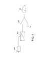
- Fig. 2 illustrates such a system.
- the generator 210 produces a master electrical signal from which the synchronization signals will be derived.
- This signal is preferably a pulse of high amplitude but may also, for example, take the form of a rising scale. In general, it will be sufficient for this signal to contain a pattern likely, either directly or indirectly by means of appropriate processing, linear (for example derivation) or non-linear (for example thresholding), to precisely define a reference time.
- This electrical signal is then delayed by a set of delays DL 1 1 ; DL 2 1 , .. DL 2 k 2 ; DL 3 1 , .. DL 3 k 3 ; .. ; DL NOT 1 , .. DL NOT k NOT organized according to a tree whose nodes 230 consist of dividers: the signal delayed by the first-order delay DL 1 1 is injected by means of the divider SP 1 1 in k 2 second rank delays DL 2 1 , .. DL 2 k 2 , the signals from these delays being themselves divided and so on.
- the signals coming from the k N delays of last rank N , DL NOT 1 , .. DL NOT k NOT form the different synchronization paths.
- the tree can be of order 2 (each node then feeding two branches), in which case the dividers can consist of 6 dB couplers, or of higher order.
- the number of branches powered by one node can vary from node to node.
- the divisors do not necessarily have an identical gain on the different output ports, in order to take into account, for example, different sizes of the sub-shafts connected to these ports, or to balance the gains of the synchronization signals.
- the delays consist of passive electrical elements, that is to say not powered by a source of electrical energy and therefore having characteristics that are not dependent on voltage or current variations of such a source.
- Passive delays will consist for example of propagation lines. We can show mathematically in a simple way, using the law of large numbers, that the jitter at the output of a propagation line presents a Gaussian probability distribution. The variance (jitter RMS) will be higher as long as the propagation line is long, the variation law being theoretically linear.
- the passive delays will be realized by means of coaxial lines.
- the coaxial lines have good immunity against noise and crosstalk, they have the remarkable property of not generating jitter, even on long lengths.
- a coaxial line of 200m has a jitter undetectable by the current measuring devices, and therefore much less than 5 ps.
- the coaxial lines are advantageously adapted, for example to a characteristic impedance of 50 ⁇ .
- the synchronization system comprises, in addition to a passive delay tree, advantageously made by coaxial lines, a second type of adjustable delays, advantageously placed in the extremal branches, that is to say the branches ending by one end of the tree.
- Fig. 3 illustrates the second embodiment in which the elements identical to those of FIG. 2 are noted identically.
- Delays of the second type, noted RDL NOT 1 , .. RDL NOT k NOT are present in the extremal branches, in series with the first type of delays DL NOT 1 , .. DL NOT k NOT .
- the master signal generated by the generator 310 is delayed in the delay tree of the first type and then by the adjustable delays RDL NOT 1 , .. RDL NOT k NOT .
- RDL NOT 1 , .. RDL NOT k NOT are capable of fine tuning, with a lower resolution than that of obtaining delays of the first type.
- An example of a second type delay is illustrated schematically in FIG. It consists of an active electronic circuit comprising a pulse detector 400, a high precision voltage ramp generator 410, a voltage comparator 420 and a pulse generator 430.
- a pulse detector 400 When an incoming pulse is detected by the pulse detector 400, a first trigger signal is transmitted to the ramp generator. The voltage at the output of the latter is compared with a threshold voltage V th by means of the comparator 420.
- the comparator can be made from an operational amplifier, a current mirror or any similar system well known to the human being. job.
- the ramp generator may consist of a very low slope integrator. The adjustment is done for example by changing the threshold voltage. This type of device makes it possible to achieve a delay resolution of the order of 2 to 3 ⁇ s.
- ⁇ T it is desired to achieve a given value of delay ⁇ T and it has a set of N delays the first type or N increasing discrete values 0 ⁇ t, ⁇ t 1, ⁇ t 2,. .., N ⁇ t 1.
- ⁇ t ⁇ (2 N -1) ⁇ t 0 it will be possible to find binary values a 0, a 1, .., a N-1 such that 0 ⁇ t 0 + a 1 t 1 + ⁇ . ., + a 1 N ⁇ t N-1 ⁇ T approach to better than ⁇ t 0/2 around.
- the delays of the second type will only be placed in the extremal branches, that is to say in the branches connected to the ends of the shaft. Adding a delay of the second type, not shared by all synchronization channels, would add a jitter additional to that already mentioned. Conversely, if one is satisfied with a setting common to a plurality of synchronization signals, an adjustable second type delay will be placed at the root of the smallest sub-tree delivering them.
- the low jitter synchronization signals generated by the system according to the invention can be used for triggering laser pulses or serve as a temporal reference (time marker) to measurement devices. More generally, the synchronization system according to the invention makes it possible to distribute precise time information to remote systems while being particularly robust. As such, it also finds application the synchronization of distributed synchronous systems, in particular in telecommunication networks.
- the described system can support the entire synchronization function or be integrated into an existing synchronization system.
Landscapes
- Physics & Mathematics (AREA)
- Nonlinear Science (AREA)
- Engineering & Computer Science (AREA)
- Plasma & Fusion (AREA)
- General Engineering & Computer Science (AREA)
- High Energy & Nuclear Physics (AREA)
- Synchronisation In Digital Transmission Systems (AREA)
- Lasers (AREA)
- Manipulation Of Pulses (AREA)
- Optical Communication System (AREA)
Applications Claiming Priority (1)
| Application Number | Priority Date | Filing Date | Title |
|---|---|---|---|
| FR0553472A FR2893464A1 (fr) | 2005-11-15 | 2005-11-15 | Dispositif de generation de signaux de synchronisation a tres faible gigue |
Publications (2)
| Publication Number | Publication Date |
|---|---|
| EP1786104A1 true EP1786104A1 (de) | 2007-05-16 |
| EP1786104B1 EP1786104B1 (de) | 2012-01-11 |
Family
ID=36649558
Family Applications (1)
| Application Number | Title | Priority Date | Filing Date |
|---|---|---|---|
| EP06123660A Not-in-force EP1786104B1 (de) | 2005-11-15 | 2006-11-08 | Anordnung zum Generieren von Synkronisiersignalen mit sehr niedrigem Jitter |
Country Status (4)
| Country | Link |
|---|---|
| EP (1) | EP1786104B1 (de) |
| AT (1) | ATE541359T1 (de) |
| ES (1) | ES2380784T3 (de) |
| FR (1) | FR2893464A1 (de) |
Cited By (1)
| Publication number | Priority date | Publication date | Assignee | Title |
|---|---|---|---|---|
| EP2700288A1 (de) * | 2011-04-20 | 2014-02-26 | Logos Technologies Inc. | Flexibler treiberlaser für träge fusionsenergie |
Citations (4)
| Publication number | Priority date | Publication date | Assignee | Title |
|---|---|---|---|---|
| US4885557A (en) * | 1988-08-08 | 1989-12-05 | Barczys Daniel A | Broadband constant voltage multicoupler |
| US20030193360A1 (en) * | 2002-04-12 | 2003-10-16 | Doo-Seop Lee | Integrated circuit devices that provide constant time delays irrespective of temperature variation |
| US20050030079A1 (en) * | 2003-08-06 | 2005-02-10 | Wei-Ming Ku | Delay circuits and related apparatus for extending delay time by active feedback elements |
| US20050179479A1 (en) * | 2002-07-19 | 2005-08-18 | Huy Nguyen | Clock distribution network with process, supply-voltage, and temperature compensation |
-
2005
- 2005-11-15 FR FR0553472A patent/FR2893464A1/fr not_active Withdrawn
-
2006
- 2006-11-08 ES ES06123660T patent/ES2380784T3/es active Active
- 2006-11-08 EP EP06123660A patent/EP1786104B1/de not_active Not-in-force
- 2006-11-08 AT AT06123660T patent/ATE541359T1/de active
Patent Citations (4)
| Publication number | Priority date | Publication date | Assignee | Title |
|---|---|---|---|---|
| US4885557A (en) * | 1988-08-08 | 1989-12-05 | Barczys Daniel A | Broadband constant voltage multicoupler |
| US20030193360A1 (en) * | 2002-04-12 | 2003-10-16 | Doo-Seop Lee | Integrated circuit devices that provide constant time delays irrespective of temperature variation |
| US20050179479A1 (en) * | 2002-07-19 | 2005-08-18 | Huy Nguyen | Clock distribution network with process, supply-voltage, and temperature compensation |
| US20050030079A1 (en) * | 2003-08-06 | 2005-02-10 | Wei-Ming Ku | Delay circuits and related apparatus for extending delay time by active feedback elements |
Non-Patent Citations (1)
| Title |
|---|
| SHUE C-W ED - INSTITUTE OF ELECTRICAL AND ELECTRONICS ENGINEERS: "CLOCK SIGNAL DISTRIBUTION NETWORK FOR HIGH SPEED TESTERS", MEETING THE TESTS OF TIME. WASHINGTON, AUG. 29 - 31, 1989, PROCEEDINGS OF THE INTERNATIONAL TEST CONFERENCE, WASHINGTON, IEEE COMP. SOC. PRESS, US, vol. CONF. 20, 29 August 1989 (1989-08-29), pages 199 - 207, XP000089948, ISBN: 0-8186-8962-5 * |
Cited By (4)
| Publication number | Priority date | Publication date | Assignee | Title |
|---|---|---|---|---|
| EP2700288A1 (de) * | 2011-04-20 | 2014-02-26 | Logos Technologies Inc. | Flexibler treiberlaser für träge fusionsenergie |
| EP2700288A4 (de) * | 2011-04-20 | 2014-12-24 | Logos Technologies Inc | Flexibler treiberlaser für träge fusionsenergie |
| US10660192B2 (en) | 2011-04-20 | 2020-05-19 | Logos Technologies Llc | Flexible driver laser for inertial fusion energy |
| US11765811B2 (en) | 2011-04-20 | 2023-09-19 | Logos Technologies Holdco, Inc. | Flexible driver laser for inertial fusion energy |
Also Published As
| Publication number | Publication date |
|---|---|
| EP1786104B1 (de) | 2012-01-11 |
| FR2893464A1 (fr) | 2007-05-18 |
| ES2380784T3 (es) | 2012-05-18 |
| ATE541359T1 (de) | 2012-01-15 |
Similar Documents
| Publication | Publication Date | Title |
|---|---|---|
| EP3371554B1 (de) | Optoelektronische vorrichtung zur verteilten messung mittels brillouin-streuung | |
| EP3738180B1 (de) | Lasersystem und verfahren zur erzeugung von laserpulsen mit sehr hoher wiederholungsrate | |
| EP2929603B1 (de) | System und verfahren zur erzeugung einer folge von ultrakurzen hochleistungslaserimpulsen | |
| EP3590159B1 (de) | Laserquelle zur emission einer gruppe von impulsen | |
| EP3164917A1 (de) | Uv-sichtbares lasersystem mit ultrakurzen leistungsstarken und/oder hochenergetischen impulsen | |
| EP1875568A2 (de) | Einrichtung zur erzeugung von durch mit photonenschichten ausgestatteten optischen fasern verstärkten laserimpulsen | |
| EP2089943B1 (de) | Lasersystem mit picosekundenimpulsemission | |
| EP1786104B1 (de) | Anordnung zum Generieren von Synkronisiersignalen mit sehr niedrigem Jitter | |
| EP1738444A1 (de) | Einrichtung zur frequenzverschiebung in einem optischen feld mit einer gepulsten laserquelle | |
| EP2726853A1 (de) | Vorrichtung zur verwaltung von impulsen in einer pumpensondenspektroskopie | |
| EP2614561B1 (de) | Verfahren und vorrichtung zur verstärkung eines optischen signals | |
| EP2082290B1 (de) | Verfahren zur einstellung der pupillenverzögerungskompensation eines konvergenten oder divergenten strahls | |
| EP2553841B1 (de) | Vorrichtung und verfahren zur verarbeitung eines optischen signals | |
| EP0344027B1 (de) | Vorrichtung zur Erzeugung einer Folge von synchronen Lichtpulsen, die von einem Einzelpuls kurzer Dauer abgeleitet werden und Apparatur zur Messung des zeitlichen Verlaufs eines derartigen Einzellichtpulses unter Verwendung dieser Vorrichtung | |
| FR3058235A1 (fr) | Dephaseur optique et dispositif optique a commande de phase ainsi que procede de reglage de la phase | |
| FR3004877A1 (fr) | Procede et systeme pour determiner un bruit de photon dans des dispositifs de communication optique | |
| WO2005125010A1 (fr) | Dispositif electronique de generation de signaux de synchronisation | |
| EP3921901B1 (de) | Lasersystem mit zeitlicher überlappung von pulsen | |
| EP0063516B1 (de) | Verfahren zum Messen von Verstärkungsänderungen in einem Laserverstärker und Vorrichtung zur Durchführung des Verfahrens | |
| WO1999017480A1 (fr) | Dispositif de synchronisation precise | |
| FR2743894A1 (fr) | Dispositif de mesure angulaire de la position d'une cible pour radar a impulsions electromagnetiques transitoires et radar en faisant application | |
| FR2930089A1 (fr) | Generateur d'impulsions electriques de forte puissance a spectre evolutif, installation et equipement mettant en oeuvre un tel generateur. | |
| Bowlan et al. | Complete measurement of nanosecond laser pulses in time | |
| FR2679716A1 (fr) | Systeme de generation d'une impulsion de haute tension. | |
| FR2976131A1 (fr) | Dispositif de commande d'emissions electromagnetiques, procede associe et systeme de detection associe. |
Legal Events
| Date | Code | Title | Description |
|---|---|---|---|
| PUAI | Public reference made under article 153(3) epc to a published international application that has entered the european phase |
Free format text: ORIGINAL CODE: 0009012 |
|
| AK | Designated contracting states |
Kind code of ref document: A1 Designated state(s): AT BE BG CH CY CZ DE DK EE ES FI FR GB GR HU IE IS IT LI LT LU LV MC NL PL PT RO SE SI SK TR |
|
| AX | Request for extension of the european patent |
Extension state: AL BA HR MK YU |
|
| 17P | Request for examination filed |
Effective date: 20071108 |
|
| AKX | Designation fees paid |
Designated state(s): AT BE BG CH CY CZ DE DK EE ES FI FR GB GR HU IE IS IT LI LT LU LV MC NL PL PT RO SE SI SK TR |
|
| RAP1 | Party data changed (applicant data changed or rights of an application transferred) |
Owner name: COMMISSARIAT A L'ENERGIE ATOMIQUE ET AUX ENERGIES |
|
| GRAP | Despatch of communication of intention to grant a patent |
Free format text: ORIGINAL CODE: EPIDOSNIGR1 |
|
| GRAS | Grant fee paid |
Free format text: ORIGINAL CODE: EPIDOSNIGR3 |
|
| GRAA | (expected) grant |
Free format text: ORIGINAL CODE: 0009210 |
|
| AK | Designated contracting states |
Kind code of ref document: B1 Designated state(s): AT BE BG CH CY CZ DE DK EE ES FI FR GB GR HU IE IS IT LI LT LU LV MC NL PL PT RO SE SI SK TR |
|
| REG | Reference to a national code |
Ref country code: GB Ref legal event code: FG4D Free format text: NOT ENGLISH |
|
| REG | Reference to a national code |
Ref country code: CH Ref legal event code: EP |
|
| REG | Reference to a national code |
Ref country code: AT Ref legal event code: REF Ref document number: 541359 Country of ref document: AT Kind code of ref document: T Effective date: 20120115 |
|
| REG | Reference to a national code |
Ref country code: IE Ref legal event code: FG4D |
|
| REG | Reference to a national code |
Ref country code: DE Ref legal event code: R096 Ref document number: 602006026947 Country of ref document: DE Effective date: 20120315 |
|
| REG | Reference to a national code |
Ref country code: SE Ref legal event code: TRGR |
|
| REG | Reference to a national code |
Ref country code: NL Ref legal event code: VDEP Effective date: 20120111 |
|
| REG | Reference to a national code |
Ref country code: ES Ref legal event code: FG2A Ref document number: 2380784 Country of ref document: ES Kind code of ref document: T3 Effective date: 20120518 |
|
| PG25 | Lapsed in a contracting state [announced via postgrant information from national office to epo] |
Ref country code: SI Free format text: LAPSE BECAUSE OF FAILURE TO SUBMIT A TRANSLATION OF THE DESCRIPTION OR TO PAY THE FEE WITHIN THE PRESCRIBED TIME-LIMIT Effective date: 20120111 |
|
| LTIE | Lt: invalidation of european patent or patent extension |
Effective date: 20120111 |
|
| PG25 | Lapsed in a contracting state [announced via postgrant information from national office to epo] |
Ref country code: NL Free format text: LAPSE BECAUSE OF FAILURE TO SUBMIT A TRANSLATION OF THE DESCRIPTION OR TO PAY THE FEE WITHIN THE PRESCRIBED TIME-LIMIT Effective date: 20120111 Ref country code: IS Free format text: LAPSE BECAUSE OF FAILURE TO SUBMIT A TRANSLATION OF THE DESCRIPTION OR TO PAY THE FEE WITHIN THE PRESCRIBED TIME-LIMIT Effective date: 20120511 Ref country code: BG Free format text: LAPSE BECAUSE OF FAILURE TO SUBMIT A TRANSLATION OF THE DESCRIPTION OR TO PAY THE FEE WITHIN THE PRESCRIBED TIME-LIMIT Effective date: 20120411 Ref country code: LT Free format text: LAPSE BECAUSE OF FAILURE TO SUBMIT A TRANSLATION OF THE DESCRIPTION OR TO PAY THE FEE WITHIN THE PRESCRIBED TIME-LIMIT Effective date: 20120111 |
|
| REG | Reference to a national code |
Ref country code: IE Ref legal event code: FD4D |
|
| PG25 | Lapsed in a contracting state [announced via postgrant information from national office to epo] |
Ref country code: PT Free format text: LAPSE BECAUSE OF FAILURE TO SUBMIT A TRANSLATION OF THE DESCRIPTION OR TO PAY THE FEE WITHIN THE PRESCRIBED TIME-LIMIT Effective date: 20120511 Ref country code: LV Free format text: LAPSE BECAUSE OF FAILURE TO SUBMIT A TRANSLATION OF THE DESCRIPTION OR TO PAY THE FEE WITHIN THE PRESCRIBED TIME-LIMIT Effective date: 20120111 Ref country code: GR Free format text: LAPSE BECAUSE OF FAILURE TO SUBMIT A TRANSLATION OF THE DESCRIPTION OR TO PAY THE FEE WITHIN THE PRESCRIBED TIME-LIMIT Effective date: 20120412 Ref country code: PL Free format text: LAPSE BECAUSE OF FAILURE TO SUBMIT A TRANSLATION OF THE DESCRIPTION OR TO PAY THE FEE WITHIN THE PRESCRIBED TIME-LIMIT Effective date: 20120111 |
|
| REG | Reference to a national code |
Ref country code: AT Ref legal event code: MK05 Ref document number: 541359 Country of ref document: AT Kind code of ref document: T Effective date: 20120111 |
|
| PG25 | Lapsed in a contracting state [announced via postgrant information from national office to epo] |
Ref country code: CY Free format text: LAPSE BECAUSE OF FAILURE TO SUBMIT A TRANSLATION OF THE DESCRIPTION OR TO PAY THE FEE WITHIN THE PRESCRIBED TIME-LIMIT Effective date: 20120111 |
|
| PG25 | Lapsed in a contracting state [announced via postgrant information from national office to epo] |
Ref country code: RO Free format text: LAPSE BECAUSE OF FAILURE TO SUBMIT A TRANSLATION OF THE DESCRIPTION OR TO PAY THE FEE WITHIN THE PRESCRIBED TIME-LIMIT Effective date: 20120111 Ref country code: CZ Free format text: LAPSE BECAUSE OF FAILURE TO SUBMIT A TRANSLATION OF THE DESCRIPTION OR TO PAY THE FEE WITHIN THE PRESCRIBED TIME-LIMIT Effective date: 20120111 Ref country code: EE Free format text: LAPSE BECAUSE OF FAILURE TO SUBMIT A TRANSLATION OF THE DESCRIPTION OR TO PAY THE FEE WITHIN THE PRESCRIBED TIME-LIMIT Effective date: 20120111 Ref country code: IE Free format text: LAPSE BECAUSE OF FAILURE TO SUBMIT A TRANSLATION OF THE DESCRIPTION OR TO PAY THE FEE WITHIN THE PRESCRIBED TIME-LIMIT Effective date: 20120111 Ref country code: DK Free format text: LAPSE BECAUSE OF FAILURE TO SUBMIT A TRANSLATION OF THE DESCRIPTION OR TO PAY THE FEE WITHIN THE PRESCRIBED TIME-LIMIT Effective date: 20120111 |
|
| PLBE | No opposition filed within time limit |
Free format text: ORIGINAL CODE: 0009261 |
|
| STAA | Information on the status of an ep patent application or granted ep patent |
Free format text: STATUS: NO OPPOSITION FILED WITHIN TIME LIMIT |
|
| PG25 | Lapsed in a contracting state [announced via postgrant information from national office to epo] |
Ref country code: SK Free format text: LAPSE BECAUSE OF FAILURE TO SUBMIT A TRANSLATION OF THE DESCRIPTION OR TO PAY THE FEE WITHIN THE PRESCRIBED TIME-LIMIT Effective date: 20120111 |
|
| 26N | No opposition filed |
Effective date: 20121012 |
|
| PG25 | Lapsed in a contracting state [announced via postgrant information from national office to epo] |
Ref country code: AT Free format text: LAPSE BECAUSE OF FAILURE TO SUBMIT A TRANSLATION OF THE DESCRIPTION OR TO PAY THE FEE WITHIN THE PRESCRIBED TIME-LIMIT Effective date: 20120111 |
|
| REG | Reference to a national code |
Ref country code: DE Ref legal event code: R097 Ref document number: 602006026947 Country of ref document: DE Effective date: 20121012 |
|
| BERE | Be: lapsed |
Owner name: COMMISSARIAT A L'ENERGIE ATOMIQUE ET AUX ENERGIES Effective date: 20121130 |
|
| REG | Reference to a national code |
Ref country code: CH Ref legal event code: PL |
|
| PG25 | Lapsed in a contracting state [announced via postgrant information from national office to epo] |
Ref country code: CH Free format text: LAPSE BECAUSE OF NON-PAYMENT OF DUE FEES Effective date: 20121130 Ref country code: LI Free format text: LAPSE BECAUSE OF NON-PAYMENT OF DUE FEES Effective date: 20121130 |
|
| PG25 | Lapsed in a contracting state [announced via postgrant information from national office to epo] |
Ref country code: BE Free format text: LAPSE BECAUSE OF NON-PAYMENT OF DUE FEES Effective date: 20121130 |
|
| PG25 | Lapsed in a contracting state [announced via postgrant information from national office to epo] |
Ref country code: TR Free format text: LAPSE BECAUSE OF FAILURE TO SUBMIT A TRANSLATION OF THE DESCRIPTION OR TO PAY THE FEE WITHIN THE PRESCRIBED TIME-LIMIT Effective date: 20120111 Ref country code: MC Free format text: LAPSE BECAUSE OF NON-PAYMENT OF DUE FEES Effective date: 20121130 |
|
| PG25 | Lapsed in a contracting state [announced via postgrant information from national office to epo] |
Ref country code: LU Free format text: LAPSE BECAUSE OF NON-PAYMENT OF DUE FEES Effective date: 20121108 |
|
| PG25 | Lapsed in a contracting state [announced via postgrant information from national office to epo] |
Ref country code: HU Free format text: LAPSE BECAUSE OF FAILURE TO SUBMIT A TRANSLATION OF THE DESCRIPTION OR TO PAY THE FEE WITHIN THE PRESCRIBED TIME-LIMIT Effective date: 20061108 |
|
| REG | Reference to a national code |
Ref country code: FR Ref legal event code: PLFP Year of fee payment: 10 |
|
| PGFP | Annual fee paid to national office [announced via postgrant information from national office to epo] |
Ref country code: DE Payment date: 20151109 Year of fee payment: 10 Ref country code: FI Payment date: 20151023 Year of fee payment: 10 Ref country code: IT Payment date: 20151118 Year of fee payment: 10 Ref country code: GB Payment date: 20151116 Year of fee payment: 10 |
|
| PGFP | Annual fee paid to national office [announced via postgrant information from national office to epo] |
Ref country code: SE Payment date: 20151117 Year of fee payment: 10 Ref country code: ES Payment date: 20151125 Year of fee payment: 10 Ref country code: FR Payment date: 20151130 Year of fee payment: 10 |
|
| REG | Reference to a national code |
Ref country code: DE Ref legal event code: R119 Ref document number: 602006026947 Country of ref document: DE |
|
| REG | Reference to a national code |
Ref country code: SE Ref legal event code: EUG |
|
| GBPC | Gb: european patent ceased through non-payment of renewal fee |
Effective date: 20161108 |
|
| PG25 | Lapsed in a contracting state [announced via postgrant information from national office to epo] |
Ref country code: FI Free format text: LAPSE BECAUSE OF NON-PAYMENT OF DUE FEES Effective date: 20161108 |
|
| REG | Reference to a national code |
Ref country code: FR Ref legal event code: ST Effective date: 20170731 |
|
| PG25 | Lapsed in a contracting state [announced via postgrant information from national office to epo] |
Ref country code: SE Free format text: LAPSE BECAUSE OF NON-PAYMENT OF DUE FEES Effective date: 20161109 |
|
| PG25 | Lapsed in a contracting state [announced via postgrant information from national office to epo] |
Ref country code: IT Free format text: LAPSE BECAUSE OF NON-PAYMENT OF DUE FEES Effective date: 20161108 Ref country code: FR Free format text: LAPSE BECAUSE OF NON-PAYMENT OF DUE FEES Effective date: 20161130 |
|
| PG25 | Lapsed in a contracting state [announced via postgrant information from national office to epo] |
Ref country code: GB Free format text: LAPSE BECAUSE OF NON-PAYMENT OF DUE FEES Effective date: 20161108 Ref country code: DE Free format text: LAPSE BECAUSE OF NON-PAYMENT OF DUE FEES Effective date: 20170601 |
|
| PG25 | Lapsed in a contracting state [announced via postgrant information from national office to epo] |
Ref country code: ES Free format text: LAPSE BECAUSE OF NON-PAYMENT OF DUE FEES Effective date: 20161109 |
|
| REG | Reference to a national code |
Ref country code: ES Ref legal event code: FD2A Effective date: 20181126 |