EP1785797A2 - Système et procédé de planification de production en visualisant des produits et des ressources dans un processus de fabrication - Google Patents
Système et procédé de planification de production en visualisant des produits et des ressources dans un processus de fabrication Download PDFInfo
- Publication number
- EP1785797A2 EP1785797A2 EP06023204A EP06023204A EP1785797A2 EP 1785797 A2 EP1785797 A2 EP 1785797A2 EP 06023204 A EP06023204 A EP 06023204A EP 06023204 A EP06023204 A EP 06023204A EP 1785797 A2 EP1785797 A2 EP 1785797A2
- Authority
- EP
- European Patent Office
- Prior art keywords
- context
- database
- article
- product
- information
- Prior art date
- Legal status (The legal status is an assumption and is not a legal conclusion. Google has not performed a legal analysis and makes no representation as to the accuracy of the status listed.)
- Granted
Links
- 238000004519 manufacturing process Methods 0.000 title claims abstract description 64
- 238000000034 method Methods 0.000 claims abstract description 86
- 230000002123 temporal effect Effects 0.000 claims abstract description 7
- 238000004891 communication Methods 0.000 claims description 15
- 238000013461 design Methods 0.000 claims description 15
- 238000012545 processing Methods 0.000 claims description 11
- 230000010354 integration Effects 0.000 claims description 8
- 238000003860 storage Methods 0.000 claims description 7
- 238000012552 review Methods 0.000 claims description 5
- 238000001914 filtration Methods 0.000 claims description 2
- 238000000429 assembly Methods 0.000 description 11
- 230000000712 assembly Effects 0.000 description 7
- 238000004458 analytical method Methods 0.000 description 4
- 230000000694 effects Effects 0.000 description 3
- 238000009434 installation Methods 0.000 description 3
- 238000011960 computer-aided design Methods 0.000 description 2
- 238000005516 engineering process Methods 0.000 description 2
- 238000011156 evaluation Methods 0.000 description 2
- 239000000463 material Substances 0.000 description 2
- 238000004590 computer program Methods 0.000 description 1
- 238000010276 construction Methods 0.000 description 1
- 239000000446 fuel Substances 0.000 description 1
- 230000003993 interaction Effects 0.000 description 1
- 238000012432 intermediate storage Methods 0.000 description 1
- 238000012423 maintenance Methods 0.000 description 1
- 230000003287 optical effect Effects 0.000 description 1
- 238000012163 sequencing technique Methods 0.000 description 1
- 238000004088 simulation Methods 0.000 description 1
- 238000012549 training Methods 0.000 description 1
- 238000012546 transfer Methods 0.000 description 1
- 230000000007 visual effect Effects 0.000 description 1
Images


Classifications
-
- G—PHYSICS
- G05—CONTROLLING; REGULATING
- G05B—CONTROL OR REGULATING SYSTEMS IN GENERAL; FUNCTIONAL ELEMENTS OF SUCH SYSTEMS; MONITORING OR TESTING ARRANGEMENTS FOR SUCH SYSTEMS OR ELEMENTS
- G05B19/00—Programme-control systems
- G05B19/02—Programme-control systems electric
- G05B19/418—Total factory control, i.e. centrally controlling a plurality of machines, e.g. direct or distributed numerical control [DNC], flexible manufacturing systems [FMS], integrated manufacturing systems [IMS], computer integrated manufacturing [CIM]
- G05B19/41805—Total factory control, i.e. centrally controlling a plurality of machines, e.g. direct or distributed numerical control [DNC], flexible manufacturing systems [FMS], integrated manufacturing systems [IMS], computer integrated manufacturing [CIM] characterised by assembly
-
- G—PHYSICS
- G05—CONTROLLING; REGULATING
- G05B—CONTROL OR REGULATING SYSTEMS IN GENERAL; FUNCTIONAL ELEMENTS OF SUCH SYSTEMS; MONITORING OR TESTING ARRANGEMENTS FOR SUCH SYSTEMS OR ELEMENTS
- G05B2219/00—Program-control systems
- G05B2219/30—Nc systems
- G05B2219/31—From computer integrated manufacturing till monitoring
- G05B2219/31027—Computer assisted manual assembly CAA, display operation, tool, result
-
- G—PHYSICS
- G05—CONTROLLING; REGULATING
- G05B—CONTROL OR REGULATING SYSTEMS IN GENERAL; FUNCTIONAL ELEMENTS OF SUCH SYSTEMS; MONITORING OR TESTING ARRANGEMENTS FOR SUCH SYSTEMS OR ELEMENTS
- G05B2219/00—Program-control systems
- G05B2219/30—Nc systems
- G05B2219/31—From computer integrated manufacturing till monitoring
- G05B2219/31029—Program for assembly, show exploded article
-
- G—PHYSICS
- G05—CONTROLLING; REGULATING
- G05B—CONTROL OR REGULATING SYSTEMS IN GENERAL; FUNCTIONAL ELEMENTS OF SUCH SYSTEMS; MONITORING OR TESTING ARRANGEMENTS FOR SUCH SYSTEMS OR ELEMENTS
- G05B2219/00—Program-control systems
- G05B2219/30—Nc systems
- G05B2219/31—From computer integrated manufacturing till monitoring
- G05B2219/31044—Assembly of modular products, variant configurability
-
- G—PHYSICS
- G05—CONTROLLING; REGULATING
- G05B—CONTROL OR REGULATING SYSTEMS IN GENERAL; FUNCTIONAL ELEMENTS OF SUCH SYSTEMS; MONITORING OR TESTING ARRANGEMENTS FOR SUCH SYSTEMS OR ELEMENTS
- G05B2219/00—Program-control systems
- G05B2219/30—Nc systems
- G05B2219/31—From computer integrated manufacturing till monitoring
- G05B2219/31053—Planning, generate assembly plans
-
- G—PHYSICS
- G05—CONTROLLING; REGULATING
- G05B—CONTROL OR REGULATING SYSTEMS IN GENERAL; FUNCTIONAL ELEMENTS OF SUCH SYSTEMS; MONITORING OR TESTING ARRANGEMENTS FOR SUCH SYSTEMS OR ELEMENTS
- G05B2219/00—Program-control systems
- G05B2219/30—Nc systems
- G05B2219/32—Operator till task planning
- G05B2219/32084—Planning of configuration of product, based on components
-
- G—PHYSICS
- G05—CONTROLLING; REGULATING
- G05B—CONTROL OR REGULATING SYSTEMS IN GENERAL; FUNCTIONAL ELEMENTS OF SUCH SYSTEMS; MONITORING OR TESTING ARRANGEMENTS FOR SUCH SYSTEMS OR ELEMENTS
- G05B2219/00—Program-control systems
- G05B2219/30—Nc systems
- G05B2219/32—Operator till task planning
- G05B2219/32359—Modeling, simulating assembly operations
-
- Y—GENERAL TAGGING OF NEW TECHNOLOGICAL DEVELOPMENTS; GENERAL TAGGING OF CROSS-SECTIONAL TECHNOLOGIES SPANNING OVER SEVERAL SECTIONS OF THE IPC; TECHNICAL SUBJECTS COVERED BY FORMER USPC CROSS-REFERENCE ART COLLECTIONS [XRACs] AND DIGESTS
- Y02—TECHNOLOGIES OR APPLICATIONS FOR MITIGATION OR ADAPTATION AGAINST CLIMATE CHANGE
- Y02P—CLIMATE CHANGE MITIGATION TECHNOLOGIES IN THE PRODUCTION OR PROCESSING OF GOODS
- Y02P90/00—Enabling technologies with a potential contribution to greenhouse gas [GHG] emissions mitigation
- Y02P90/02—Total factory control, e.g. smart factories, flexible manufacturing systems [FMS] or integrated manufacturing systems [IMS]
Definitions
- This invention relates generally to information technology, and more particularly, to systems and methods for production planning in manufacturing processes.
- Engineering information typically includes engineering drawings and parts lists that cooperatively form an engineering product plan that describes how materials, components assemblies and sub-assemblies must be combined to form the desired product.
- a manufacturing process plan is subsequently compiled so that the identified parts in the desired product may be properly scheduled for assembly on the factory floor. Suitable scheduling and coordination is particularly important in complex projects since factors such as the overall cost of the project, the time required for completion of the project, and the risk of failure must be accurately estimated. In addition, other variables of importance such as the overall efficiency of the project need to be accurately estimated.
- the manufacturing process plan typically includes factory floor planning, tool planning and scheduling, compilation of work plans for assembly personnel, assembly plans, and other similar activities.
- the planned configuration, as expressed in the manufacturing process plan may require assembly of the product in a sequence not contemplated by the designed configuration, as expressed in the engineering process plan. Since existing methods generally do not permit variability in tasks or resources in the process to be effectively resolved, conflicts that arise during the product assembly must often be resolved informally on the factory floor, which in turn, often requires expensive and time-consuming rework.
- a system for production planning includes a first database configured to retain engineering information for a selected article of manufacture, and a second database configured to retain process information for the selected article.
- a processor is provided that receives a selected portion of the engineering information from the first database and a selected portion of the process information from the second database and combines the selected portions to generate a temporal graphical view of a selected portion of the article.
- the present invention relates to systems and methods for production planning in a manufacturing process. Many specific details of certain embodiments of the invention are set forth in the following description and in FIGURES 1 through 5 to provide a thorough understanding of such embodiments. One skilled in the art, however, will understand that the present invention may have additional embodiments, or that the present invention may be practiced without several of the details described in the following description.
- FIGURE 1 is a block diagrammatic view of an apparatus 10 for production planning in a manufacturing process, according to an embodiment of the invention.
- the apparatus 10 includes a processing unit 12 that generally includes any programmable electronic device that is operable to receive programming instructions and input data, and to process the data according to the programming instructions. Although a single processing unit is shown in FIGURE 1, the processing unit 12 may be comprised of a plurality of processing units that are coupled serially or in parallel so that each processing unit performs a selected portion of a total. computational task performed by the processing unit 12.
- the apparatus 10 also includes a product information database 14 that is operable to store engineering information of various types.
- the engineering information database 14 may include digital representations of selected component parts that collectively comprise the product generated in the manufacturing process.
- the digital representations may include two-dimensional and/or three-dimensional digital models that are compatible with known computer-aided design (CAD) systems, such as the CATIA digital modeling system, available from Daussault Systemes Corporation of Suresnes, France, although other suitable digital modeling systems exist.
- CAD computer-aided design
- Other engineering information may be included in the database 14.
- the database 14 may include drawing trees that permit engineering drawings to be accessed in an ordered manner, as well as parts lists that define the configuration of the product.
- Other information stored in the database 14 may include part tolerances and process specifications such as torque requirements, and any other desired information.
- the engineering information database 14 may be compiled as disclosed in a co-pending and commonly owned U.S. Patent Application Serial No. 11/013,311 filed on December 15, 2004 , entitled “Systems and Methods for Process-Driven Bill of Material", which application is incorporated by reference herein.
- the apparatus 10 also includes a process information database 16 that is operable to store process-related information for the product generated in the manufacturing process.
- the process information database 16 may include part resource and planning relationships for a selected component part or assembly.
- the planning relationships may include precedence networks that describe a predetermined assembly sequence for a component part or assembly.
- a precedence network is a multi-dependency representation of a project that includes the various activities in the project depicted as nodes, and further includes sequence elements that express at least a temporal relationship between the various nodes.
- the process structures may include data structures that are created as disclosed in a co-pending and commonly owned U.S. Patent Application Serial No.
- FIGURE 1 shows the databases 14 and 16 as discrete operational units, it is understood that the informational content of the databases 14 and 16 may be incorporated into a single unit.
- the apparatus 10 includes a communications system 18 that is configured to communicate with the processor 12. Accordingly, the communications system 18 may be used to provide engineering and/or planning data to the processor 12, which may suitably format the engineering and/or planning data for storage in the database 14 and the database 16.
- the communication system 18 may include a wide area network (WAN) or a local area network (LAN), but in a particular embodiment, the communications system 18 includes an internet-based system.
- the communications system 18 is coupled to one or more requestors 20 that communicate with the processor 12 through the communications system 18.
- the one or more requestors 20 thus provide engineering and/or planning data to the processor 12, and receive suitably processed data from the processor 12 through the communications system 18.
- the apparatus 10 includes a storage device 22 that receives processed information from the processing unit 12, which will be described in greater detail below.
- the storage device 22 may also serve as an intermediate storage location for information generated by the processor 12 before the information is transferred to one or more information requestors 20.
- the requestors 20 may transfer engineering and/or planning data to the apparatus 10 through the communications system 18 so that the data is available to the processor 12.
- the engineering data generally describes the configuration of a desired product, such as a commercial aircraft
- the planning data generally comprises a scheduling definition, which is generally expressed as a precedence network.
- the planning data describes the sequence definition that may be used to define the schedule.
- the processing unit 12 accordingly processes the data to generate "context" information that reflects a selected assembly or sub-assembly at a desired stage of assembly.
- hydraulics, fuel and electrical systems, and structural design may generally be executed and planned by different organizations that may develop respective designs and planning information with minimal mutual interaction. Accordingly, one or more conflicts may result during integration of the foregoing systems and structures designs. For example, at a selected integration step, it may be determined that the assembly must be partially disassembled in order to permit the installation of other systems and/or structural components because the prior integration steps were not properly ordered. Further, at the selected integration step, it may become apparent that sufficient access is not present to admit a tool and/or a hand to effect the integration step, due to an error in the design of a system and/or a structural component.
- the context information generated within the processor 12 includes two and/or three-dimensional digital models (e.g., models created using the CATIA digital modeling system, or other similar modeling systems) that may be retrieved from the product information database 14 that are selectively combined with information in the process information database 16 to provide a graphical view of an assembly at a selected integration step.
- the product information (stored in database 14) and/or the process information (stored in database 16) the information may be readily altered to specify a different design and/or assembly sequence to avoid the observed conflicts. Accordingly, conflicts between the product, process and resource definitions may be advantageously resolved prior to the release of the foregoing definitions.
- FIGURE 2 is a partial schematic view of a method 30 of creating and managing a manufacturing plan in a manufacturing process, according to another embodiment of the invention.
- the method 30 includes compiling a product information source 32 and a process information source 34 that are generally separately compiled and provide design configuration information for components, assemblies and/or sub-assemblies, and assembly sequencing and planning information, respectively.
- the product information source 32 and the process information source 34 thus include information for a variety of interrelated systems that are generally prepared by various engineering and planning groups.
- selected portions of the product information source 32 and the product information source 34 may be extracted and processed (as described in detail with reference to FIGURE 1) to generate a plurality of contexts 36.
- the contexts 36 are graphical representations of selected assemblies and/or sub-assemblies that may be reviewed by affected engineering and/or planning groups so that conflicts resulting from planning and/or engineering errors may be detected.
- the design of components that comprise the selected assembly may introduce conflicts that preclude assembly efficiency by requiring partial disassembly of a previously assembled object so that access for a hand, a tool, or other required access, may be obtained.
- planning information conflicts may introduce the foregoing access difficulties, and may also introduce difficulties of different kinds.
- the planning information may require the use of selected installation tools, which are not subsequently removed. Consequently, the installation tools may undesirably be incorporated into the assembly.
- revised information may be introduced into at least one of the product information source 32 and the process information source 34, so that a revised plurality of the contexts 36 may be generated and evaluated.
- the evaluation of the contexts 36 may proceed by visually examining each of the contexts 36 under various selected viewing conditions. For example, and in one selected embodiment, selected portions of the assembly may be highlighted using a desired color while other portions of the assembly are uniformly presented in a contrasting color, so that the selected portion may be clearly viewed. In another specific embodiment, the selected portions of the assembly may be desirably highlighted, while other portions are viewed as "grayed" with lower contrast than the highlighted portions.
- the selected portion of the assembly may be viewed using a minimum viewing option that shows all of the structure and processes that have occurred in a preceding path (as expressed, for example, in a precedence network corresponding to the assembly).
- a maximum viewing option would be operable to provide a comprehensive view that includes not only a preceding path, but contributions from parallel paths in the precedence network also.
- Contexts may also be selectively viewed by applying a filter to the context that is based upon certain selected attributes of the assembly so that selected portions of the context may be viewed. Filtering the context advantageously permits a viewer to remove extraneous detail and view only the data that is relevant to the viewer.
- the context may also be viewed dynamically, so that selected portions of the context may be viewed in a desired position.
- the context may be viewed in a position that is oriented in approximately about the same position that would obtain in the actual assembly. Accordingly, a viewer of the context may conveniently review ergonomic positions of an individual effecting the assembly, tool clearances available to the individual, and other similar details.
- a final context 38 is generated that reflects a relatively matured informational content in the product information source 32 and/or the process information source 34.
- the final context 38 may advantageously be used as a baseline context for future design and planning efforts, and may also be used as a training aid for instructing personnel in the proper assembly of a selected assembly. Still other uses for the final context 38 are possible. For example, it may be advantageously used to develop repair and/or maintenance operations. It is understood, however, that the final context may be continuously evolving, so that no entirely definitive context may exist.
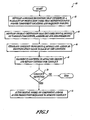
- FIGURE 3 is a flowchart that will be used to describe a method 40 of managing product and process information in a manufacturing process, according to still another embodiment of the invention.
- a process definition is developed that includes a plurality of production tasks that reference part and/or component locations, required tooling and a temporal representation of the production tasks, as expressed for example, in a precedence network.
- a product definition is formulated that includes digital representations of various components, assemblies and sub-assemblies. In a specific embodiment of the present invention, the digital models are created and viewable using the CATIA digital modeling system.
- contexts are generated using the product definition and the process definition and an identification value may be assigned to each of the contexts.
- the identification value may be used to identify an affected group (e.g., the identification value may be an address that corresponds to the affected group), or it may refer to a particular version of the context.
- the contexts are communicated to the one or more affected groups for review.
- the affected groups may include planning personnel and/or design personnel that may engage in a colloquy regarding planning and/or the design of the desired product.
- the digital model of a selected component and/or a production sequence may be selectively altered to remove the conflict, as shown in block 52. If no conflicts are detected, the method terminates, as also shown at block 50. Otherwise, the method 40 recursively returns to block 46, and revised contexts are generated.
- FIGURE 4 is a system 400 for performing a manufacturing process in accordance with an embodiment of the present invention.
- the components of the system 400 are of generally-known construction, and will not be described in detail. For the sake of brevity, only significant details and aspects of the system 400 will be described.
- the system 400 includes a computer 402 having a central processing unit (CPU) 404 and a memory component 406.
- the memory component 406 may include one or more memory modules, such as Random Access Memory (RAM) modules, Read Only Memory (ROM) modules, Dynamic Random Access Memory (DRAM) modules, and any other suitable memory modules...
- RAM Random Access Memory
- ROM Read Only Memory
- DRAM Dynamic Random Access Memory
- the computer 402 also includes an input/output (I/O) component 408 that may include a variety of known I/O devices, including network connections, video and graphics cards, disk drives or other computer-readable media drives, displays, or any other suitable I/O modules.
- I/O input/output
- a data bus 410 operatively couples the CPU 404, memory component 406, and the I/O component 408.
- the system 400 embodiment shown in FIGURE 4 further includes a data base 412 operatively coupled to the computer 402.
- the database 412 is operatively coupled to the computer 402 via a first communication link 416.
- the database 412 includes a first portion 413 adapted to store product information, a second portion 414 adapted to store process information, and a third portion 415 adapted to store processed information from the computer 402.
- the system 400 further includes a control component 420 having a monitor 422 and a command input device 424 (e.g. a keyboard, an audio-visual input device, etc.).
- a second communication link 418 operatively couples the control component 420 to the computer 402.
- the system 400 also includes an auxiliary output device 426 coupled to the computer 402 by a third communication link 428.
- the auxiliary output device 426 may include a printer, a compact disk (CD) burner, a storage device, a communication port, or any other desired output device.
- a machine-readable medium may be used to store a set of machine-readable instructions (e.g. a computer program) into the computer 402, wherein the machine -readable instructions embody a method of performing manufacturing operations in accordance with the teachings of the present invention.
- the machine-readable medium may be any type of medium which can store data that is readable by the computer 402, including, for example, a floppy disk, CD ROM, optical storage disk, magnetic tape, flash memory card, digital video disk, RAM, ROM, or any other suitable storage medium.
- the machine-readable medium, or the instructions stored thereon may be temporarily or permanently installed in any desired component of the system 400, including, for example, the I/O component 408, the memory component 406, and the auxiliary output device 426. Alternately, the machine-readable instructions may be implemented directly into one or more components of the computer 402, without the assistance of the machine-readable medium.
- the computer 402 may be configured to perform one or more of the aspects of the methods of manufacturing described above.
- an operator 430 may input a command through the command input device 424 to cause the computer to retrieve product information from the first portion 413 of the data base 412 and process information from the second portion 414 of the data base 412.
- the computer 402 may then use a set of software instructions stored in the computer 402 (e.g. in the memory component 406) that performs one or more aspects of the methods of manufacturing described above on the product and process information, and may then transmit processed information to the third portion 415 of the data base 412.
- a set of software instructions stored in the computer 402 e.g. in the memory component 406
- one or more aspects of the various processes described above may be implemented in the computer 402 using any suitable programmable or semi-programmable hardware components (e.g. EPROM components).
- Results of the processes performed by the computer 402 in accordance with one or more embodiments of the invention may be transmitted via the data bus 410 to the I/O component 408.
- the results may also be transmitted to the control component 420 and to the auxiliary output device 426 via the second and third communications links 418 and 428.
- the operator 430 may view the results of the one or more methods on the control monitor 422, and may take appropriate action, including revising analysis parameters and inputs, and continuing or repeating the one or more embodiments of analysis methods using different product and process information as desired.
- FIGURE 5 is a side elevational view of an aircraft 900 having one or more components 902 fabricated using methods and systems for manufacturing in accordance with embodiments of the invention.
- the aircraft 900 generally includes a fuselage 905 including wing assemblies 906, a tail assembly 908, and a landing assembly 910.
- the aircraft 900 further includes one or more propulsion units 904, a control system 912 (not visible), and a host of other systems and subsystems that enable proper operation of the aircraft 900.
- systems and methods in accordance with the present invention may be utilized in the fabrication of any number of components 902 of the aircraft 900, including, for example, the various components and sub-components of the tail assembly 908, the wing assemblies 906, the fuselage 905, the propulsion units 904, and any other suitable portion of the aircraft 900.
- embodiments of the present invention may also be used to manufacture the aircraft 900 in its entirety.
- the aircraft 900 shown in FIGURE 5 is generally representative of a commercial passenger aircraft, including, for example, the 737, 747, 757, 767, 777, and 7E7 models commercially-available from The Boeing Company of Chicago, Illinois, the inventive systems and methods disclosed herein may also be employed in the assembly of virtually any other types of aircraft.
- embodiments of the present invention may be applied to the manufacture and assembly of other passenger aircraft, fighter aircraft, cargo aircraft, rotary aircraft, and any other types of manned or unmanned aircraft, including those described, for example, in The Illustrated Encyclopedia of Military Aircraft by Enzo Angelucci, published by Book Sales Publishers, September 2001 , and in Jane's A11 the World's Aircraft published by Jane's Information Group of Coulsdon, Surrey, United Kingdom, which texts are incorporated herein by reference.
Applications Claiming Priority (1)
| Application Number | Priority Date | Filing Date | Title |
|---|---|---|---|
| US11/270,399 US20070106410A1 (en) | 2005-11-09 | 2005-11-09 | Systems and methods for production planning by visualizing products and resources in a manufacturing process |
Publications (3)
| Publication Number | Publication Date |
|---|---|
| EP1785797A2 true EP1785797A2 (fr) | 2007-05-16 |
| EP1785797A3 EP1785797A3 (fr) | 2010-03-03 |
| EP1785797B1 EP1785797B1 (fr) | 2019-01-09 |
Family
ID=37561265
Family Applications (1)
| Application Number | Title | Priority Date | Filing Date |
|---|---|---|---|
| EP06023204.8A Not-in-force EP1785797B1 (fr) | 2005-11-09 | 2006-11-08 | Système et procédé de planification de production en visualisant des produits et des ressources dans un processus de fabrication |
Country Status (2)
| Country | Link |
|---|---|
| US (1) | US20070106410A1 (fr) |
| EP (1) | EP1785797B1 (fr) |
Cited By (3)
| Publication number | Priority date | Publication date | Assignee | Title |
|---|---|---|---|---|
| EP2019371A1 (fr) * | 2007-07-25 | 2009-01-28 | The Boeing Company | Planification de procédé tridimensionnelle |
| US8239362B1 (en) | 2010-06-11 | 2012-08-07 | The Boeing Company | Using metadata fragments as authoritative manufacturing work instructions |
| US8996151B2 (en) | 2005-11-09 | 2015-03-31 | The Boeing Company | Visualization of product build using precedence transversal method |
Families Citing this family (16)
| Publication number | Priority date | Publication date | Assignee | Title |
|---|---|---|---|---|
| US8131392B2 (en) * | 2008-02-25 | 2012-03-06 | The Boeing Company | System and method for using manufacturing states of vehicle products for display of a manufacturing process |
| KR101179492B1 (ko) * | 2011-08-08 | 2012-09-07 | 주식회사 쌤스인터내셔널 | 3차원 모델 조립 장치 및 방법 |
| US9904896B2 (en) * | 2011-09-12 | 2018-02-27 | The Boeing Company | Object management system |
| US9076116B2 (en) | 2013-02-04 | 2015-07-07 | The Boeing Company | Alpha-chain constraints for process planning |
| US9792573B2 (en) | 2013-02-04 | 2017-10-17 | The Boeing Company | System for modeling production of a product |
| US9492900B2 (en) | 2013-03-15 | 2016-11-15 | The Boeing Company | Condition of assembly visualization system based on build cycles |
| US9880694B2 (en) | 2013-05-09 | 2018-01-30 | The Boeing Company | Shop order status visualization system |
| US10481768B2 (en) | 2013-04-12 | 2019-11-19 | The Boeing Company | Nonconformance identification and visualization system and method |
| US10061481B2 (en) | 2013-02-28 | 2018-08-28 | The Boeing Company | Methods and devices for visually querying an aircraft based on an area of an image |
| US9612725B1 (en) | 2013-02-28 | 2017-04-04 | The Boeing Company | Nonconformance visualization system |
| US9870444B2 (en) | 2013-03-05 | 2018-01-16 | The Boeing Company | Shop order status visualization system |
| US20140298216A1 (en) | 2013-03-28 | 2014-10-02 | The Boeing Company | Visualization of an Object Using a Visual Query System |
| US10416857B2 (en) | 2013-05-09 | 2019-09-17 | The Boeing Company | Serial number control visualization system |
| US9547303B2 (en) | 2013-10-18 | 2017-01-17 | The Boeing Company | Managing the manufacturing lifecycle of fasteners of a product |
| EP2990894B1 (fr) * | 2014-08-25 | 2018-09-26 | The Boeing Company | Système de visualisation de commande de numéro de série |
| US10685147B2 (en) | 2016-02-29 | 2020-06-16 | The Boeing Company | Non-conformance mapping and visualization |
Citations (2)
| Publication number | Priority date | Publication date | Assignee | Title |
|---|---|---|---|---|
| EP0483039A2 (fr) * | 1990-10-24 | 1992-04-29 | International Business Machines Corporation | Méthode et système de contrôle de la version de modifications techniques |
| US20020080194A1 (en) * | 2000-12-25 | 2002-06-27 | Fujitsu Limited | Computer readable recording medium storing program for managing CAD data |
Family Cites Families (17)
| Publication number | Priority date | Publication date | Assignee | Title |
|---|---|---|---|---|
| US5247651A (en) * | 1990-04-17 | 1993-09-21 | At&T Bell Laboratories | Interactive computer program specification and simulation system |
| US5479343A (en) * | 1990-11-28 | 1995-12-26 | Hitachi, Ltd. | Production planning system |
| IL112660A (en) * | 1994-03-31 | 1998-01-04 | Minnesota Mining & Mfg | System integrating active and simulated decision- making processes |
| US5596502A (en) * | 1994-11-14 | 1997-01-21 | Sunoptech, Ltd. | Computer system including means for decision support scheduling |
| US5867713A (en) * | 1995-04-05 | 1999-02-02 | International Business Machines Corporation | Committing an install plan object for the network installation of application programs |
| EP0770967A3 (fr) * | 1995-10-26 | 1998-12-30 | Koninklijke Philips Electronics N.V. | Système d'aide de décision pour la gestion d'une chaíne de l'alimentation agile |
| JP2927232B2 (ja) * | 1996-01-29 | 1999-07-28 | 富士ゼロックス株式会社 | 分散シミュレーション装置および分散シミュレーション方法 |
| US5971589A (en) * | 1996-05-06 | 1999-10-26 | Amadasoft America, Inc. | Apparatus and method for managing and distributing design and manufacturing information throughout a sheet metal production facility |
| US6233493B1 (en) * | 1998-09-16 | 2001-05-15 | I2 Technologies, Inc. | Computer-implemented product development planning method |
| AU4359400A (en) * | 1999-04-21 | 2000-11-02 | Interactual Technologies, Inc. | System, method and article of manufacture for updating content stored on a portable storage medium |
| US6820042B1 (en) * | 1999-07-23 | 2004-11-16 | Opnet Technologies | Mixed mode network simulator |
| US6826518B1 (en) * | 1999-09-20 | 2004-11-30 | Ut-Battelle, Llc | Method for distributed agent-based non-expert simulation of manufacturing process behavior |
| AU2001259545A1 (en) * | 2000-05-04 | 2001-11-12 | Eric C. Berg | Optimizing the availability of a buffered industrial process |
| AU2002226938A1 (en) * | 2000-11-16 | 2002-05-27 | Michael F. Juras | Product development process |
| JP2003091309A (ja) * | 2001-07-11 | 2003-03-28 | Class Technology Co Ltd | 生産管理システムおよび生産管理方法 |
| WO2004001633A2 (fr) * | 2002-06-25 | 2003-12-31 | Volkswagen | Procede et systeme de simulation pour simuler des processus de deroulement de travaux, et produit de programme informatique correspondant et support de memorisation correspondant, lisible par ordinateur |
| US7321804B2 (en) * | 2004-12-15 | 2008-01-22 | The Boeing Company | Method for process-driven bill of material |
-
2005
- 2005-11-09 US US11/270,399 patent/US20070106410A1/en not_active Abandoned
-
2006
- 2006-11-08 EP EP06023204.8A patent/EP1785797B1/fr not_active Not-in-force
Patent Citations (2)
| Publication number | Priority date | Publication date | Assignee | Title |
|---|---|---|---|---|
| EP0483039A2 (fr) * | 1990-10-24 | 1992-04-29 | International Business Machines Corporation | Méthode et système de contrôle de la version de modifications techniques |
| US20020080194A1 (en) * | 2000-12-25 | 2002-06-27 | Fujitsu Limited | Computer readable recording medium storing program for managing CAD data |
Cited By (4)
| Publication number | Priority date | Publication date | Assignee | Title |
|---|---|---|---|---|
| US8996151B2 (en) | 2005-11-09 | 2015-03-31 | The Boeing Company | Visualization of product build using precedence transversal method |
| EP2019371A1 (fr) * | 2007-07-25 | 2009-01-28 | The Boeing Company | Planification de procédé tridimensionnelle |
| EP2216740A3 (fr) * | 2007-07-25 | 2011-03-02 | The Boeing Company | Planification de procédé tridimensionnelle |
| US8239362B1 (en) | 2010-06-11 | 2012-08-07 | The Boeing Company | Using metadata fragments as authoritative manufacturing work instructions |
Also Published As
| Publication number | Publication date |
|---|---|
| EP1785797B1 (fr) | 2019-01-09 |
| EP1785797A3 (fr) | 2010-03-03 |
| US20070106410A1 (en) | 2007-05-10 |
Similar Documents
| Publication | Publication Date | Title |
|---|---|---|
| EP1785797B1 (fr) | Système et procédé de planification de production en visualisant des produits et des ressources dans un processus de fabrication | |
| US8996151B2 (en) | Visualization of product build using precedence transversal method | |
| US8131392B2 (en) | System and method for using manufacturing states of vehicle products for display of a manufacturing process | |
| EP2863280B1 (fr) | Gestion du cycle de vie de la fabrication d'éléments de fixation d'un produit | |
| EP2216740A2 (fr) | Planification de procédé tridimensionnelle | |
| JP2008524717A (ja) | プロセス駆動される部品表のためのシステム及び方法 | |
| US20080021583A1 (en) | Computer implemented method for defining an input product | |
| EP3286611B1 (fr) | Procédé et système pour contrôle de validation de données transdisciplinaires dans un système d'ingénierie multidisciplinaire | |
| Abdelaziz et al. | Adaptive Software Development for developing safety critical software | |
| Dolezal | Success factors for digital mock-ups (DMU) in complex aerospace product development | |
| Dollinger et al. | Be lean—how to fit a model-based system architecture development process based on arp4754 into an agile environment | |
| Baum et al. | Applying 3D product modeling technology to shipbuilding | |
| EP1892659A2 (fr) | Ensemble de données de planification de processus de supportabilité selon le modèle | |
| US11347903B2 (en) | Passenger service unit placement layout system for aircraft | |
| Fuchs et al. | Formalized knowledge management for the aircraft cabin design process | |
| CA3058200C (fr) | Procede et systeme permettant de mettre a jour un plan de simulation | |
| Li | Digital assembly process design for aircraft systems | |
| JP2004280719A (ja) | シミュレーションモデルの自動生成装置 | |
| OSULLIVAN | Development and operation of a flexible manufacturing system using structured techniques | |
| Bhanumathi et al. | Information technology model for product lifecycle engineering | |
| LUNDQVIST et al. | Model Based Definition: The Main Effects of Implementing Model Based Definition in an Automotive Manufacturing Industry | |
| Brown et al. | The factory is virtual... The savings are real | |
| Jones et al. | Simulation based design for ship design and acquisition | |
| Cole et al. | Simulation Assessment Validation Environment (SAVE). Software User's Manual | |
| DI GIRONIMO et al. | FABIO PELUSO |
Legal Events
| Date | Code | Title | Description |
|---|---|---|---|
| PUAI | Public reference made under article 153(3) epc to a published international application that has entered the european phase |
Free format text: ORIGINAL CODE: 0009012 |
|
| AK | Designated contracting states |
Kind code of ref document: A2 Designated state(s): AT BE BG CH CY CZ DE DK EE ES FI FR GB GR HU IE IS IT LI LT LU LV MC NL PL PT RO SE SI SK TR |
|
| AX | Request for extension of the european patent |
Extension state: AL BA HR MK YU |
|
| PUAL | Search report despatched |
Free format text: ORIGINAL CODE: 0009013 |
|
| AK | Designated contracting states |
Kind code of ref document: A3 Designated state(s): AT BE BG CH CY CZ DE DK EE ES FI FR GB GR HU IE IS IT LI LT LU LV MC NL PL PT RO SE SI SK TR |
|
| AX | Request for extension of the european patent |
Extension state: AL BA HR MK RS |
|
| 17P | Request for examination filed |
Effective date: 20100903 |
|
| 17Q | First examination report despatched |
Effective date: 20101006 |
|
| AKX | Designation fees paid |
Designated state(s): AT BE BG CH CY CZ DE DK EE ES FI FR GB GR HU IE IS IT LI LT LU LV MC NL PL PT RO SE SI SK TR |
|
| GRAP | Despatch of communication of intention to grant a patent |
Free format text: ORIGINAL CODE: EPIDOSNIGR1 |
|
| STAA | Information on the status of an ep patent application or granted ep patent |
Free format text: STATUS: GRANT OF PATENT IS INTENDED |
|
| INTG | Intention to grant announced |
Effective date: 20180815 |
|
| RIN1 | Information on inventor provided before grant (corrected) |
Inventor name: VANHORNE, MARK E. Inventor name: BOUFFIOU, CARL E. Inventor name: FRANZEN, STEVE Inventor name: KEHNER, WILLIAM A. Inventor name: SCHREIBER, ROBERT J. Inventor name: ANELLE, JOE |
|
| GRAS | Grant fee paid |
Free format text: ORIGINAL CODE: EPIDOSNIGR3 |
|
| GRAA | (expected) grant |
Free format text: ORIGINAL CODE: 0009210 |
|
| STAA | Information on the status of an ep patent application or granted ep patent |
Free format text: STATUS: THE PATENT HAS BEEN GRANTED |
|
| AK | Designated contracting states |
Kind code of ref document: B1 Designated state(s): AT BE BG CH CY CZ DE DK EE ES FI FR GB GR HU IE IS IT LI LT LU LV MC NL PL PT RO SE SI SK TR |
|
| REG | Reference to a national code |
Ref country code: GB Ref legal event code: FG4D |
|
| REG | Reference to a national code |
Ref country code: CH Ref legal event code: EP Ref country code: AT Ref legal event code: REF Ref document number: 1088066 Country of ref document: AT Kind code of ref document: T Effective date: 20190115 |
|
| REG | Reference to a national code |
Ref country code: DE Ref legal event code: R096 Ref document number: 602006057246 Country of ref document: DE |
|
| REG | Reference to a national code |
Ref country code: IE Ref legal event code: FG4D |
|
| REG | Reference to a national code |
Ref country code: NL Ref legal event code: MP Effective date: 20190109 |
|
| REG | Reference to a national code |
Ref country code: LT Ref legal event code: MG4D |
|
| PG25 | Lapsed in a contracting state [announced via postgrant information from national office to epo] |
Ref country code: NL Free format text: LAPSE BECAUSE OF FAILURE TO SUBMIT A TRANSLATION OF THE DESCRIPTION OR TO PAY THE FEE WITHIN THE PRESCRIBED TIME-LIMIT Effective date: 20190109 |
|
| REG | Reference to a national code |
Ref country code: AT Ref legal event code: MK05 Ref document number: 1088066 Country of ref document: AT Kind code of ref document: T Effective date: 20190109 |
|
| PG25 | Lapsed in a contracting state [announced via postgrant information from national office to epo] |
Ref country code: LT Free format text: LAPSE BECAUSE OF FAILURE TO SUBMIT A TRANSLATION OF THE DESCRIPTION OR TO PAY THE FEE WITHIN THE PRESCRIBED TIME-LIMIT Effective date: 20190109 Ref country code: PL Free format text: LAPSE BECAUSE OF FAILURE TO SUBMIT A TRANSLATION OF THE DESCRIPTION OR TO PAY THE FEE WITHIN THE PRESCRIBED TIME-LIMIT Effective date: 20190109 Ref country code: FI Free format text: LAPSE BECAUSE OF FAILURE TO SUBMIT A TRANSLATION OF THE DESCRIPTION OR TO PAY THE FEE WITHIN THE PRESCRIBED TIME-LIMIT Effective date: 20190109 Ref country code: SE Free format text: LAPSE BECAUSE OF FAILURE TO SUBMIT A TRANSLATION OF THE DESCRIPTION OR TO PAY THE FEE WITHIN THE PRESCRIBED TIME-LIMIT Effective date: 20190109 Ref country code: PT Free format text: LAPSE BECAUSE OF FAILURE TO SUBMIT A TRANSLATION OF THE DESCRIPTION OR TO PAY THE FEE WITHIN THE PRESCRIBED TIME-LIMIT Effective date: 20190509 Ref country code: ES Free format text: LAPSE BECAUSE OF FAILURE TO SUBMIT A TRANSLATION OF THE DESCRIPTION OR TO PAY THE FEE WITHIN THE PRESCRIBED TIME-LIMIT Effective date: 20190109 |
|
| PG25 | Lapsed in a contracting state [announced via postgrant information from national office to epo] |
Ref country code: GR Free format text: LAPSE BECAUSE OF FAILURE TO SUBMIT A TRANSLATION OF THE DESCRIPTION OR TO PAY THE FEE WITHIN THE PRESCRIBED TIME-LIMIT Effective date: 20190410 Ref country code: BG Free format text: LAPSE BECAUSE OF FAILURE TO SUBMIT A TRANSLATION OF THE DESCRIPTION OR TO PAY THE FEE WITHIN THE PRESCRIBED TIME-LIMIT Effective date: 20190409 Ref country code: IS Free format text: LAPSE BECAUSE OF FAILURE TO SUBMIT A TRANSLATION OF THE DESCRIPTION OR TO PAY THE FEE WITHIN THE PRESCRIBED TIME-LIMIT Effective date: 20190509 Ref country code: LV Free format text: LAPSE BECAUSE OF FAILURE TO SUBMIT A TRANSLATION OF THE DESCRIPTION OR TO PAY THE FEE WITHIN THE PRESCRIBED TIME-LIMIT Effective date: 20190109 |
|
| REG | Reference to a national code |
Ref country code: DE Ref legal event code: R097 Ref document number: 602006057246 Country of ref document: DE |
|
| PG25 | Lapsed in a contracting state [announced via postgrant information from national office to epo] |
Ref country code: AT Free format text: LAPSE BECAUSE OF FAILURE TO SUBMIT A TRANSLATION OF THE DESCRIPTION OR TO PAY THE FEE WITHIN THE PRESCRIBED TIME-LIMIT Effective date: 20190109 Ref country code: EE Free format text: LAPSE BECAUSE OF FAILURE TO SUBMIT A TRANSLATION OF THE DESCRIPTION OR TO PAY THE FEE WITHIN THE PRESCRIBED TIME-LIMIT Effective date: 20190109 Ref country code: IT Free format text: LAPSE BECAUSE OF FAILURE TO SUBMIT A TRANSLATION OF THE DESCRIPTION OR TO PAY THE FEE WITHIN THE PRESCRIBED TIME-LIMIT Effective date: 20190109 Ref country code: DK Free format text: LAPSE BECAUSE OF FAILURE TO SUBMIT A TRANSLATION OF THE DESCRIPTION OR TO PAY THE FEE WITHIN THE PRESCRIBED TIME-LIMIT Effective date: 20190109 Ref country code: RO Free format text: LAPSE BECAUSE OF FAILURE TO SUBMIT A TRANSLATION OF THE DESCRIPTION OR TO PAY THE FEE WITHIN THE PRESCRIBED TIME-LIMIT Effective date: 20190109 Ref country code: SK Free format text: LAPSE BECAUSE OF FAILURE TO SUBMIT A TRANSLATION OF THE DESCRIPTION OR TO PAY THE FEE WITHIN THE PRESCRIBED TIME-LIMIT Effective date: 20190109 Ref country code: CZ Free format text: LAPSE BECAUSE OF FAILURE TO SUBMIT A TRANSLATION OF THE DESCRIPTION OR TO PAY THE FEE WITHIN THE PRESCRIBED TIME-LIMIT Effective date: 20190109 |
|
| PLBE | No opposition filed within time limit |
Free format text: ORIGINAL CODE: 0009261 |
|
| STAA | Information on the status of an ep patent application or granted ep patent |
Free format text: STATUS: NO OPPOSITION FILED WITHIN TIME LIMIT |
|
| 26N | No opposition filed |
Effective date: 20191010 |
|
| PG25 | Lapsed in a contracting state [announced via postgrant information from national office to epo] |
Ref country code: SI Free format text: LAPSE BECAUSE OF FAILURE TO SUBMIT A TRANSLATION OF THE DESCRIPTION OR TO PAY THE FEE WITHIN THE PRESCRIBED TIME-LIMIT Effective date: 20190109 |
|
| PG25 | Lapsed in a contracting state [announced via postgrant information from national office to epo] |
Ref country code: TR Free format text: LAPSE BECAUSE OF FAILURE TO SUBMIT A TRANSLATION OF THE DESCRIPTION OR TO PAY THE FEE WITHIN THE PRESCRIBED TIME-LIMIT Effective date: 20190109 |
|
| REG | Reference to a national code |
Ref country code: CH Ref legal event code: PL |
|
| PG25 | Lapsed in a contracting state [announced via postgrant information from national office to epo] |
Ref country code: LU Free format text: LAPSE BECAUSE OF NON-PAYMENT OF DUE FEES Effective date: 20191108 Ref country code: LI Free format text: LAPSE BECAUSE OF NON-PAYMENT OF DUE FEES Effective date: 20191130 Ref country code: CH Free format text: LAPSE BECAUSE OF NON-PAYMENT OF DUE FEES Effective date: 20191130 Ref country code: MC Free format text: LAPSE BECAUSE OF FAILURE TO SUBMIT A TRANSLATION OF THE DESCRIPTION OR TO PAY THE FEE WITHIN THE PRESCRIBED TIME-LIMIT Effective date: 20190109 |
|
| REG | Reference to a national code |
Ref country code: BE Ref legal event code: MM Effective date: 20191130 |
|
| PG25 | Lapsed in a contracting state [announced via postgrant information from national office to epo] |
Ref country code: IE Free format text: LAPSE BECAUSE OF NON-PAYMENT OF DUE FEES Effective date: 20191108 |
|
| PG25 | Lapsed in a contracting state [announced via postgrant information from national office to epo] |
Ref country code: BE Free format text: LAPSE BECAUSE OF NON-PAYMENT OF DUE FEES Effective date: 20191130 |
|
| PG25 | Lapsed in a contracting state [announced via postgrant information from national office to epo] |
Ref country code: CY Free format text: LAPSE BECAUSE OF FAILURE TO SUBMIT A TRANSLATION OF THE DESCRIPTION OR TO PAY THE FEE WITHIN THE PRESCRIBED TIME-LIMIT Effective date: 20190109 |
|
| PG25 | Lapsed in a contracting state [announced via postgrant information from national office to epo] |
Ref country code: HU Free format text: LAPSE BECAUSE OF FAILURE TO SUBMIT A TRANSLATION OF THE DESCRIPTION OR TO PAY THE FEE WITHIN THE PRESCRIBED TIME-LIMIT; INVALID AB INITIO Effective date: 20061108 |
|
| PGFP | Annual fee paid to national office [announced via postgrant information from national office to epo] |
Ref country code: DE Payment date: 20211126 Year of fee payment: 16 Ref country code: GB Payment date: 20211129 Year of fee payment: 16 Ref country code: FR Payment date: 20211124 Year of fee payment: 16 |
|
| REG | Reference to a national code |
Ref country code: DE Ref legal event code: R119 Ref document number: 602006057246 Country of ref document: DE |
|
| GBPC | Gb: european patent ceased through non-payment of renewal fee |
Effective date: 20221108 |
|
| PG25 | Lapsed in a contracting state [announced via postgrant information from national office to epo] |
Ref country code: GB Free format text: LAPSE BECAUSE OF NON-PAYMENT OF DUE FEES Effective date: 20221108 Ref country code: DE Free format text: LAPSE BECAUSE OF NON-PAYMENT OF DUE FEES Effective date: 20230601 |
|
| PG25 | Lapsed in a contracting state [announced via postgrant information from national office to epo] |
Ref country code: FR Free format text: LAPSE BECAUSE OF NON-PAYMENT OF DUE FEES Effective date: 20221130 |