EP1785710A2 - Drucksensorgehäuse und -konfiguration - Google Patents
Drucksensorgehäuse und -konfiguration Download PDFInfo
- Publication number
- EP1785710A2 EP1785710A2 EP06123811A EP06123811A EP1785710A2 EP 1785710 A2 EP1785710 A2 EP 1785710A2 EP 06123811 A EP06123811 A EP 06123811A EP 06123811 A EP06123811 A EP 06123811A EP 1785710 A2 EP1785710 A2 EP 1785710A2
- Authority
- EP
- European Patent Office
- Prior art keywords
- sensor
- sss
- chip
- sensing die
- pressure
- Prior art date
- Legal status (The legal status is an assumption and is not a legal conclusion. Google has not performed a legal analysis and makes no representation as to the accuracy of the status listed.)
- Ceased
Links
Images


Classifications
-
- G—PHYSICS
- G01—MEASURING; TESTING
- G01L—MEASURING FORCE, STRESS, TORQUE, WORK, MECHANICAL POWER, MECHANICAL EFFICIENCY, OR FLUID PRESSURE
- G01L9/00—Measuring steady of quasi-steady pressure of fluid or fluent solid material by electric or magnetic pressure-sensitive elements; Transmitting or indicating the displacement of mechanical pressure-sensitive elements, used to measure the steady or quasi-steady pressure of a fluid or fluent solid material, by electric or magnetic means
- G01L9/0041—Transmitting or indicating the displacement of flexible diaphragms
- G01L9/0051—Transmitting or indicating the displacement of flexible diaphragms using variations in ohmic resistance
- G01L9/0052—Transmitting or indicating the displacement of flexible diaphragms using variations in ohmic resistance of piezoresistive elements
- G01L9/0055—Transmitting or indicating the displacement of flexible diaphragms using variations in ohmic resistance of piezoresistive elements bonded on a diaphragm
-
- G—PHYSICS
- G01—MEASURING; TESTING
- G01L—MEASURING FORCE, STRESS, TORQUE, WORK, MECHANICAL POWER, MECHANICAL EFFICIENCY, OR FLUID PRESSURE
- G01L19/00—Details of, or accessories for, apparatus for measuring steady or quasi-steady pressure of a fluent medium insofar as such details or accessories are not special to particular types of pressure gauges
- G01L19/0092—Pressure sensor associated with other sensors, e.g. for measuring acceleration or temperature
-
- G—PHYSICS
- G01—MEASURING; TESTING
- G01L—MEASURING FORCE, STRESS, TORQUE, WORK, MECHANICAL POWER, MECHANICAL EFFICIENCY, OR FLUID PRESSURE
- G01L19/00—Details of, or accessories for, apparatus for measuring steady or quasi-steady pressure of a fluent medium insofar as such details or accessories are not special to particular types of pressure gauges
- G01L19/14—Housings
- G01L19/147—Details about the mounting of the sensor to support or covering means
-
- G—PHYSICS
- G01—MEASURING; TESTING
- G01L—MEASURING FORCE, STRESS, TORQUE, WORK, MECHANICAL POWER, MECHANICAL EFFICIENCY, OR FLUID PRESSURE
- G01L9/00—Measuring steady of quasi-steady pressure of fluid or fluent solid material by electric or magnetic pressure-sensitive elements; Transmitting or indicating the displacement of mechanical pressure-sensitive elements, used to measure the steady or quasi-steady pressure of a fluid or fluent solid material, by electric or magnetic means
- G01L9/02—Measuring steady of quasi-steady pressure of fluid or fluent solid material by electric or magnetic pressure-sensitive elements; Transmitting or indicating the displacement of mechanical pressure-sensitive elements, used to measure the steady or quasi-steady pressure of a fluid or fluent solid material, by electric or magnetic means by making use of variations in ohmic resistance, e.g. of potentiometers, electric circuits therefor, e.g. bridges, amplifiers or signal conditioning
- G01L9/06—Measuring steady of quasi-steady pressure of fluid or fluent solid material by electric or magnetic pressure-sensitive elements; Transmitting or indicating the displacement of mechanical pressure-sensitive elements, used to measure the steady or quasi-steady pressure of a fluid or fluent solid material, by electric or magnetic means by making use of variations in ohmic resistance, e.g. of potentiometers, electric circuits therefor, e.g. bridges, amplifiers or signal conditioning of piezo-resistive devices
- G01L9/065—Measuring steady of quasi-steady pressure of fluid or fluent solid material by electric or magnetic pressure-sensitive elements; Transmitting or indicating the displacement of mechanical pressure-sensitive elements, used to measure the steady or quasi-steady pressure of a fluid or fluent solid material, by electric or magnetic means by making use of variations in ohmic resistance, e.g. of potentiometers, electric circuits therefor, e.g. bridges, amplifiers or signal conditioning of piezo-resistive devices with temperature compensating means
Definitions
- the present invention relates generally to pressure sensors and, more particularly, to a pressure sensor housing and configuration for a unique sensing die.
- a pressure sensor is typically either a gage, differential or absolute pressure sensor. With gage sensors, pressure readings are referenced to atmospheric pressure. That is, zero output is at atmospheric pressure.
- a differential pressure sensor is similar to a gauge pressure sensor, but instead of measuring pressure relative to ambient atmospheric pressure, differential measurements are taken with respect to a specific reference pressure. Absolute pressure sensors sense a pressure compared to near zero pressure or a vacuum reference. That is, an output of the pressure sensor is zero at full vacuum pressure.
- An absolute pressure reference is commonly used in applications such as calibration, altitude simulation, and a variety of low absolute pressure regulation situations, for example.
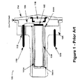
- FIG. 1 illustrates a typical pressure sensor 100 that includes two Wheatstone bridges with sixteen resistors on a sensing die 102. A sensing side of the die is ionically bonded to a tube 104 through which pressure is measured. The die 102 and tube 104 are then soldered into a stainless steal header 106. The sensing die 102 is wire-bonded 108 to gold plated pins 110, so that an output of the sensing die 102 can be received from the pressure sensor 100. The gold plated pins 110 are hermetically sealed within the steal header 106 with a glass seal 112. The non-sensing side of the sensing die 102 is sealed by a weld cover 114 within a vacuum. Getter 116 is placed within the weld cover to absorb helium and other gases during soldering.
- the pressure sensor 100 includes hermetically sealed pins 110 and a vacuum sealed cover 114.
- the seals provide the reference pressure, for example, a vacuum reference, for the pressure sensor 100.
- a pressure measurement from the sensing die should not be affected by ambient pressure. If the pressure sensor 100 was alternatively configured as a gauge or differential pressure sensor, hermetic and vacuum seals may still be required.
- sealing output pins and the sensing die from ambient pressures can be the most difficult and/or time-consuming step.
- a sensor in an exemplary embodiment, includes a single sensing die and a wafer cover.
- the single sensing die has a tangential resistance when current flow is tangential to the sensing die and a radial resistance when current flow is radial to the sensing die.
- the wafer cover has a recessed portion, and is bonded to a surface of the single sensing die to provide a vacuum seal within the recessed portion between the wafer cover and the single sensing die.
- the wafer cover is hermetically bonded to the single sensing die to provide the vacuum seal.
- a pressure and temperature sensor in another embodiment, includes a header coupled to a cover, and a sensing die positioned in an area between the header and cover.
- a wafer cover that has a recessed portion is hermetically bonded to the sensing die to provide a vacuum seal as a reference pressure within the recessed portion. In this manner, the header and cover does not need to be hermetically sealed to provide a vacuum reference for the sensing die.
- a sensor in yet another embodiment, includes a single square sensing die that has a tangential resistance when current flow is tangential to the sensing die and a radial resistance when current flow is radial to the sensing die, and by changing a direction of current through the single square sensing die a tangential voltage across the tangential resistance and a radial voltage across the radial resistance can be measured to determine a magnitude of a pressure applied to the single square sensing die and to determine a magnitude of an ambient temperature of the single square sensing die.
- a sensor cover is hermetically bonded to the single square sensing die so as to provide a vacuum reference for the sensing die. Further, a header coupled to a cover form a housing within which the single square sensing die is positioned.
- the present application describes a pressure sensor housing and configuration for a single-square-sensor (SSS) sensing die, as described in U.S. Patent Application Serial Number 11/271,701 to Russell Johnson , entitled “Pressure and Temperature Sensing Element.”
- SSS single-square-sensor
- SSS single square sensor
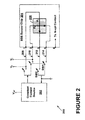
- the sensing element 200 includes a constant current source 202 that drives a single square silicon (SSS) sensor chip 204.
- the constant current source 202 may provide a current of 1ma, for example.
- Switches connect the current source 202 to the SSS chip 204. As shown, a first switch, SW1, connects the constant current source 202 to the SSS chip 204 at nodes 2 and 4. A second switch, SW2, connects the constant current source 202 to the SSS chip 204 at nodes 1 and 3.
- the switches SW1 and SW2 could be integrated on the SSS chip 204 itself.
- the SSS chip 204 may be a solid-state device.
- the SSS chip 204 includes a single square silicon (SSS) element 206, which senses both applied pressures and ambient temperatures.
- the SSS element 206 has two inputs: one input is a radial voltage input from lead 208 and the other input is a tangential input from lead 210.
- the SSS element 206 accordingly has two outputs: one output is a radial voltage output (V r ) at lead 212, and the other output is a tangential voltage output (V t ) at lead 214.
- the sensing element 200 may further include switches SW3 and SW4 (not shown) to control power supplied to the SSS sensor chip 204. Additional switches may be controlled by the current source 202 or by an independent controller (not shown). In particular, additional switches may control whether power with positive or negative polarity (as seen by the sensor chip 204) is provided to the sensor chip 204.
- switches SW3 and SW4 may be controlled by the current source 202 or by an independent controller (not shown). In particular, additional switches may control whether power with positive or negative polarity (as seen by the sensor chip 204) is provided to the sensor chip 204.
- the SSS chip 204 may also include a diaphragm (not shown) upon which the SSS element 206 is mounted.
- a pressure is applied to the diaphragm, a lattice structure of the SSS chip becomes stressed and alters a mobility of charge carriers in the SSS element 206 temporarily changing a radial (e.g., strain in the direction from a center of the sensor toward the edge) and tangential (e.g., strain perpendicular to the radial strain) resistance of the SSS element 206.
- V r radial voltage output
- V t tangential voltage output
- the SSS chip 204 may comprise a silicon-on-insulator structure or a bulk silicon structure, for example.
- Figure 3 illustrates a side view of one embodiment of such a structure.
- the SSS chip 204 is mounted on a diaphragm 300 that has an inner edge 302 and an outer edge 304.
- the sensing element further includes legs 306 for connecting the diaphragm 300 to any circuit or other substrate.
- any number of substrate layers e.g., layer 308 may be deposited onto the diaphragm 300 onto which the sensor chip 204 may be placed, for example. As shown, the sensor chip 204 is positioned on the inner edge 302 of the diaphragm 300.
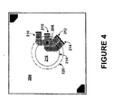
- FIG 4 illustrates one example of a magnified pictoral view of the SSS chip 204.
- the SSS chip 204 is illustrated mounted on a diaphragm 216.
- the diaphragm 216 includes an inner edge 218 and an outer edge 220.
- the SSS chip 204 may be mounted on the inner edge 218 of the diaphragm.
- a maximum stress of the flexible membrane may occur on the inner edge 218 of the diaphragm 216, and thus, the SSS chip 204 can be positioned to sense the maximum amount of stress, for example.
- Applied pressures to the diaphragm 216 will deflect a flexible membrane of the diaphragm 216, and these stresses in the membrane will change resistances of the SSS chip 204.
- Such changes in resistance in the SSS chip 204 will cause a change in output voltages of the SSS chip 204 that are proportional to the applied pressures. For example, an approximate 0.5mm deflection in the flexible membrane of the diaphragm can be detected in a change in resistances within the SSS chip 204.
- a thickness and diameter of the diaphragm 216 can be selected to be give rise to a certain deflection, which is equivalent to a certain change in resistance.
- a thick diaphragm may result in a small change in resistance on the SSS chip 204 due to an applied pressure
- a thin diaphragm may result in a large change in resistance on the SSS chip 204 from the applied pressure.
- Voltage outputs from the sensing element correspond to a certain pressure and temperature reading.
- the exact correspondence depends on the aspect ratio of the diaphragm 300, and a size of circuit elements relative to a strain localization. Other factors can also affect the correspondence between voltages and pressure/temperature readings.
- the sensing element 10 may be used in a medium pressure application, such as measuring 500-3000 PSI and in high temperature applications.
- FIG. 5 is a flowchart depicting an example of functional blocks of a method for measuring pressure and temperature using a common sensing element.
- the common sensing element may be the SSS chip 204, for example, as illustrated in Figure 2.
- the common sensing element has a tangential resistance when current flow is tangential to the common sensing element and a radial resistance when current flow is radial to the common sensing element.
- a current is applied tangentially through the common sensing element.
- a tangential voltage across the tangential resistance can then be measured, as shown at block 502.
- a current is applied radially through the common sensing element.
- a radial voltage across the radial resistance can then be measured, as shown at block 506.
- a magnitude of a pressure applied to the common sensing element and a magnitude of an ambient temperature of the common sensing element can be determined using the tangential voltage and the radial voltage, as shown at block 508.
- a single piezo-resistive element may be operated as both a radial piezo-resistor (Rr) and as a tangential piezo-resistor (Rt), so that when operated with a constant current source, the difference in voltage drop across Rr and Rt is proportional to a measurement of pressure and the sum of a voltage drop across Rr and Rt is proportional to a measurement of temperature.
- outputs of the SSS chip 204 can be associated with a pressure or temperature as applied to the sensing element 200.
- Two resistances can be measured across the square silicon element 206.
- a resistance for the condition where current flow is tangential to the square 206 is defined as the tangential resistance R t . This condition applies when SW1 is closed and SW2 is open.
- a resistance for the condition where current flow is radial to the square 206 is defined as the radial resistance R r . This condition applies when SW2 is closed and SW1 is open.
- V t 1 + d ⁇ R l R t ⁇ R t ⁇ I cc
- I cc the current applied from the constant current source
- d ⁇ R t R t the tangential piezoresistive gage factor (e.g., constant value that relates a radial strain or defamation of the surface to the change in resistance and is dependent upon the properties of the materials of the sensor).
- V r 1 - d ⁇ R r R r ⁇ R r ⁇ I cc
- d ⁇ R r R r is the radial piezoresistive gage factor
- an applied pressure to the SSS chip 204 is proportional to the difference between the tangential and radial voltage measured across the SSS element 206.
- Equation (4) is that of a full Wheatstone bridge pressure sensor configuration operating with a constant voltage source of V ref .
- the sensing element 10 can provide the same pressure voltage output as that of full Wheatstone bridge sensors, but accomplishes such with a single piezo-resistive element rather than four, for example.
- outputs of the SSS chip 204 can also be associated with an ambient temperature of the sensing element 200.
- an ambient temperature of the SSS chip 204 is proportional to the sum of the tangential and radial voltage measured across the SSS element 206.
- the same common sensing element e.g., the SSS element 206
- the same common sensing element e.g., the SSS element 206
- compensates of pressure measurements using the temperature measurements may be more accurate since the pressure and temperature measurements originate from the same sensing element.
- a power polarity switching technique can be applied to the current source 202.
- the current source 202 provides power in a radial and tangential direction.
- the current source 202 could be arranged to provide power having a positive and negative polarity.
- the current source 202 could then apply power to the sensing element 200 in a radial direction having a positive polarity, then in the radial direction having a negative polarity, and same for the tangential direction.
- U.S. Patent Application Serial No. 11/272,306 to Thomas Stratton entitled "Method and System of Providing Power to a Pressure and Temperature Sensing Element," the entire contents of which are herein incorporated by reference, as if fully set forth in this description.
- the SSS chip 204 may be mounted or positioned within any number of housings depending on the type of pressure to be detected.
- Figure 6 illustrates one embodiment of a pressure sensor 600 including the SSS chip 204.
- the sensor 600 includes a glass wafer 602 hermetically bonded 603 to the SSS chip 204.
- the SSS chip 204 is positioned between a header 604 and a cover 606, which can be glued together using an epoxy 608, for example.
- a tube 610 such as a pyrex tube, is connected to the SSS chip 204 through which pressure is sensed, for example.
- a vacuum reference for an absolute pressure sensor is created and maintained using custom hermetic packages and elaborate vacuum sealing techniques.
- a vacuum seal is created and thus less emphasis is placed on hermetically sealing the remainder of the sensor 600.
- the header 606 and cover 604 can be coupled using epoxy instead of a one-shot weld.
- the tube 610 can be glued within the header 604 with epoxy as well, since the wafer 602 creates the vacuum seal for the SSS chip 204.
- the wafer 602 may be a silicon or glass wafer with an etched cavity or recessed portion 605 that can be aligned over the SSS pressure sensor diaphragm and bonded 603 to the pressure sensor wafer while in a vacuum, using gold, germanium, lead, tin or silver, for example.
- the recessed portion 605 provides space into which a diaphragm of the SSS chip 204 can deflect.
- the wafer bond creates a vacuum reference on the SSS chip 204.
- the silicon or glass bonding wafer also leaves areas open for to wirebond to the pressure sensor bond pads for electrical contact.
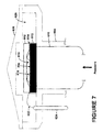
- Figure 7 illustrates one example of the pressure sensor 600.
- Electrical contact 612 is present on the SSS chip 204 to which wirebonds 616 connect and transfer electrical signals from the SSS chip 204 to electrical contact 612, and further through wirebond 622 to leads, such as lead 624.
- wirebonds 616 may be necessary since electrical signals can be transferred from the SSS chip 204 to the electrical contact 612 through integrated circuitry, for example.
- an area 618 provides a vacuum seal for the SSS chip 204. Therefore, area 620 does not need to be hermetically sealed.
- the SSS chip 204 comprises only one resistive element, which is used for both temperature and pressure sensing, only 4 to 6 wire bonds, for example, are needed leaving more surface area on the SSS chip 204 to which the wafer 602 can be bonded. Providing a large surface to which the wafer 602 can be bonded enables for batch processing, e.g., such as 400 at a time. Further, the wafer 602 does not need to cover the entire surface area of the SSS chip 204, so more area is left open to wire bond pins to the SSS chip 204.
- the wafer 602 is bonded to the circuit side or electrical surface of the SSS chip 204, as illustrated in Figure 7, to provide a unique configuration adapted to use of the SSS chip 204.
- the SSS chip design permits anodic bonding between the wafer 602 and the die to create a vacuum reference on the circuit side of the SSS chip 204. This enables use of batch processing and use of less expensive packaging and/or processing for sensor assembly with little impact to sensor performance, for example.
- any type of pressure sensor can be created with the SSS chip 204, e.g., such as a differential, gage or absolute pressure sensor.
- the pressure sensor is an absolute pressure sensor, and the space or volume enclosed by the wafer 602 can be evacuated down to a bard vacuum prior to the hermetic sealing of the wafer 602 to establish a vacuum reference for the absolute pressure sensor.
- the SSS chip 204 will be flexed as a function of the differential in pressure. Such flexing, in turn, will produce an output voltage signal corresponding to a pressure and temperature that is sensed, as explained above.
- the hermetic seal between the wafer 602 and the SSS chip 204 provides or permits a vacuum reference for an absolute pressure sensor.
- the seal provides environmental protection for the active or circuit side of the SSS chip 204.
- the hermetic seal provides for pressure sensor stability over a period of time.
- the sensor packaging e.g., header 604 and cover 606, may be stainless steal, ceramic, plastic, aluminum or others depending on the application of the sensor.
- the entire sensor may be approximately 0.75 inches by 0.75 inches, and as such, the sensor may be used within integrated circuit applications, for example.
- the sensor can be other sizes as well.
- the SSS sensor described within many embodiments herein can be used to reduce a complexity of typical Wheatstone bridge sensors, to increase pressure sensitivity and reduce in on-chip voltage, which reduces average power usage, and to reduce thermal gradients between pressure and temperature measurements, for example.
- a vacuum reference is created on chip, and thus a hermetic packaging is not needed.
- no welding for hermetic seals is necessary, but rather other glues can be used, such as epoxy.
Landscapes
- Physics & Mathematics (AREA)
- General Physics & Mathematics (AREA)
- Chemical & Material Sciences (AREA)
- Analytical Chemistry (AREA)
- Measuring Fluid Pressure (AREA)
Applications Claiming Priority (2)
| Application Number | Priority Date | Filing Date | Title |
|---|---|---|---|
| US73597605P | 2005-11-10 | 2005-11-10 | |
| US11/557,661 US7597005B2 (en) | 2005-11-10 | 2006-11-08 | Pressure sensor housing and configuration |
Publications (2)
| Publication Number | Publication Date |
|---|---|
| EP1785710A2 true EP1785710A2 (de) | 2007-05-16 |
| EP1785710A3 EP1785710A3 (de) | 2008-06-25 |
Family
ID=37702242
Family Applications (1)
| Application Number | Title | Priority Date | Filing Date |
|---|---|---|---|
| EP06123811A Ceased EP1785710A3 (de) | 2005-11-10 | 2006-11-10 | Drucksensorgehäuse und -konfiguration |
Country Status (3)
| Country | Link |
|---|---|
| US (1) | US7597005B2 (de) |
| EP (1) | EP1785710A3 (de) |
| JP (1) | JP2007132946A (de) |
Cited By (2)
| Publication number | Priority date | Publication date | Assignee | Title |
|---|---|---|---|---|
| EP1962075A2 (de) | 2007-02-23 | 2008-08-27 | Silicon Micro Sensors GmbH | Drucksensorverbindung |
| DE202008011684U1 (de) | 2008-09-03 | 2008-12-24 | Silicon Micro Sensors Gmbh | Drucksensor |
Families Citing this family (12)
| Publication number | Priority date | Publication date | Assignee | Title |
|---|---|---|---|---|
| US8175835B2 (en) * | 2006-05-17 | 2012-05-08 | Honeywell International Inc. | Flow sensor with conditioning-coefficient memory |
| JP4916006B2 (ja) * | 2007-02-28 | 2012-04-11 | 株式会社山武 | 圧力センサ |
| US20090288484A1 (en) * | 2008-05-21 | 2009-11-26 | Honeywell International Inc. | Integrated mechanical package design for combi sensor apparatus |
| US8082797B2 (en) * | 2009-11-11 | 2011-12-27 | Honeywell International Inc. | Pressure sensor assembly |
| US7985659B1 (en) | 2010-03-31 | 2011-07-26 | Freescale Semiconductor, Inc. | Semiconductor device with a controlled cavity and method of formation |
| US8297127B2 (en) | 2011-01-07 | 2012-10-30 | Honeywell International Inc. | Pressure sensor with low cost packaging |
| US8718981B2 (en) | 2011-05-09 | 2014-05-06 | Honeywell International Inc. | Modular sensor assembly including removable sensing module |
| US20130098160A1 (en) * | 2011-10-25 | 2013-04-25 | Honeywell International Inc. | Sensor with fail-safe media seal |
| DE102013110368A1 (de) | 2013-09-19 | 2015-03-19 | Endress + Hauser Gmbh + Co. Kg | Druckmessumformer |
| GB2521163A (en) | 2013-12-11 | 2015-06-17 | Melexis Technologies Nv | Semiconductor pressure sensor |
| US10317297B2 (en) * | 2013-12-11 | 2019-06-11 | Melexis Technologies Nv | Semiconductor pressure sensor |
| CN209326840U (zh) | 2018-12-27 | 2019-08-30 | 热敏碟公司 | 压力传感器及压力变送器 |
Citations (9)
| Publication number | Priority date | Publication date | Assignee | Title |
|---|---|---|---|---|
| US271701A (en) | 1883-02-06 | goodwin | ||
| US272306A (en) | 1883-02-13 | Steam-engine | ||
| US3123788A (en) | 1964-03-03 | Piezoresistive gage | ||
| US4321832A (en) | 1980-03-07 | 1982-03-30 | Rockwell International Corporation | High accuracy measuring apparatus |
| EP0195232A2 (de) | 1985-03-20 | 1986-09-24 | Hitachi, Ltd. | Piezoresistiver Belastungsfühler |
| EP0225095A2 (de) | 1985-11-15 | 1987-06-10 | Transamerica Delaval Inc. | Zweiachsige Dehnungsmessstreifensysteme |
| US5459351A (en) | 1994-06-29 | 1995-10-17 | Honeywell Inc. | Apparatus for mounting an absolute pressure sensor |
| US20030167851A1 (en) | 2002-01-30 | 2003-09-11 | Parker Gregory D. | Absolute micromachined silicon pressure sensor with backside hermetic cover and method of making the same |
| WO2005103639A1 (en) | 2004-04-20 | 2005-11-03 | Honeywell International Inc. | Quartz sensor system and producing method thereof |
Family Cites Families (2)
| Publication number | Priority date | Publication date | Assignee | Title |
|---|---|---|---|---|
| US5349867A (en) | 1991-12-02 | 1994-09-27 | Kavlico Corporation | Sensitive resistive pressure transducer |
| US7278319B2 (en) * | 2005-11-10 | 2007-10-09 | Honeywell International Inc. | Pressure and temperature sensing element |
-
2006
- 2006-11-08 US US11/557,661 patent/US7597005B2/en not_active Expired - Fee Related
- 2006-11-10 EP EP06123811A patent/EP1785710A3/de not_active Ceased
- 2006-11-10 JP JP2006305043A patent/JP2007132946A/ja not_active Withdrawn
Patent Citations (9)
| Publication number | Priority date | Publication date | Assignee | Title |
|---|---|---|---|---|
| US271701A (en) | 1883-02-06 | goodwin | ||
| US272306A (en) | 1883-02-13 | Steam-engine | ||
| US3123788A (en) | 1964-03-03 | Piezoresistive gage | ||
| US4321832A (en) | 1980-03-07 | 1982-03-30 | Rockwell International Corporation | High accuracy measuring apparatus |
| EP0195232A2 (de) | 1985-03-20 | 1986-09-24 | Hitachi, Ltd. | Piezoresistiver Belastungsfühler |
| EP0225095A2 (de) | 1985-11-15 | 1987-06-10 | Transamerica Delaval Inc. | Zweiachsige Dehnungsmessstreifensysteme |
| US5459351A (en) | 1994-06-29 | 1995-10-17 | Honeywell Inc. | Apparatus for mounting an absolute pressure sensor |
| US20030167851A1 (en) | 2002-01-30 | 2003-09-11 | Parker Gregory D. | Absolute micromachined silicon pressure sensor with backside hermetic cover and method of making the same |
| WO2005103639A1 (en) | 2004-04-20 | 2005-11-03 | Honeywell International Inc. | Quartz sensor system and producing method thereof |
Cited By (4)
| Publication number | Priority date | Publication date | Assignee | Title |
|---|---|---|---|---|
| EP1962075A2 (de) | 2007-02-23 | 2008-08-27 | Silicon Micro Sensors GmbH | Drucksensorverbindung |
| DE202008011684U1 (de) | 2008-09-03 | 2008-12-24 | Silicon Micro Sensors Gmbh | Drucksensor |
| EP2161559A2 (de) | 2008-09-03 | 2010-03-10 | Silicon Micro Sensors GmbH | Drucksensor und Verfahren zu seiner Herstellung |
| US7954384B2 (en) | 2008-09-03 | 2011-06-07 | Silicon Micro Sensors Gmbh | Pressure sensor and manufacturing method of the same |
Also Published As
| Publication number | Publication date |
|---|---|
| EP1785710A3 (de) | 2008-06-25 |
| US20070113668A1 (en) | 2007-05-24 |
| JP2007132946A (ja) | 2007-05-31 |
| US7597005B2 (en) | 2009-10-06 |
Similar Documents
| Publication | Publication Date | Title |
|---|---|---|
| US7597005B2 (en) | Pressure sensor housing and configuration | |
| US8230745B2 (en) | Wet/wet differential pressure sensor based on microelectronic packaging process | |
| US8297125B2 (en) | Media isolated differential pressure sensor with cap | |
| US7278319B2 (en) | Pressure and temperature sensing element | |
| EP0354479B1 (de) | Halbleiterdruckwandler | |
| US5437189A (en) | Dual absolute pressure sensor and method thereof | |
| US5483834A (en) | Suspended diaphragm pressure sensor | |
| EP3118599B1 (de) | Drucksensor mit eingebautem belastungspuffer | |
| CA1239806A (en) | Capacitive sensing cell made of brittle material | |
| EP2120029B1 (de) | ASIC-kompensierter Drucksensor mit gelötetem Sensorchipbefestigung | |
| EP1969334A2 (de) | Drucksensor mit durch siliciumfritten gebundener kappe | |
| KR19980032489A (ko) | 반도체 압력 센서 | |
| US7698951B2 (en) | Pressure-sensor apparatus | |
| WO2006098842A1 (en) | Media isolated absolute pressure sensor | |
| JPH07103837A (ja) | 物理量検出センサ | |
| CN107782485B (zh) | 集成有共模误差补偿的差压传感器 | |
| US20020073783A1 (en) | Pressure sensor | |
| CN109341932B (zh) | 一种压力传感器芯片及其制造方法 | |
| US7178403B2 (en) | Transducer responsive to pressure, vibration/acceleration and temperature and methods of fabricating the same | |
| EP1785709A2 (de) | Methode und System zur Stromversogung eines Temperatur- und Drucksensors. | |
| US20220268611A1 (en) | Flow sensor | |
| Melvas et al. | A diode-based two-wire solution for temperature-compensated piezoresistive pressure sensors | |
| US4140023A (en) | Differential pressure transducer | |
| CN216246925U (zh) | 一种降低输出漂移的mems压力传感器芯片 | |
| JPH10142086A (ja) | 半導体圧力センサとその製造方法及びこれを用いた差圧伝送器 |
Legal Events
| Date | Code | Title | Description |
|---|---|---|---|
| PUAI | Public reference made under article 153(3) epc to a published international application that has entered the european phase |
Free format text: ORIGINAL CODE: 0009012 |
|
| AK | Designated contracting states |
Kind code of ref document: A2 Designated state(s): AT BE BG CH CY CZ DE DK EE ES FI FR GB GR HU IE IS IT LI LT LU LV MC NL PL PT RO SE SI SK TR |
|
| AX | Request for extension of the european patent |
Extension state: AL BA HR MK YU |
|
| PUAL | Search report despatched |
Free format text: ORIGINAL CODE: 0009013 |
|
| AK | Designated contracting states |
Kind code of ref document: A3 Designated state(s): AT BE BG CH CY CZ DE DK EE ES FI FR GB GR HU IE IS IT LI LT LU LV MC NL PL PT RO SE SI SK TR |
|
| AX | Request for extension of the european patent |
Extension state: AL BA HR MK RS |
|
| 17P | Request for examination filed |
Effective date: 20081211 |
|
| 17Q | First examination report despatched |
Effective date: 20090116 |
|
| AKX | Designation fees paid |
Designated state(s): DE FR GB |
|
| STAA | Information on the status of an ep patent application or granted ep patent |
Free format text: STATUS: THE APPLICATION HAS BEEN REFUSED |
|
| 18R | Application refused |
Effective date: 20110709 |