EP1785601A1 - Internal Combustion Engine Blow-By Gas Ventilation System - Google Patents
Internal Combustion Engine Blow-By Gas Ventilation System Download PDFInfo
- Publication number
- EP1785601A1 EP1785601A1 EP06124079A EP06124079A EP1785601A1 EP 1785601 A1 EP1785601 A1 EP 1785601A1 EP 06124079 A EP06124079 A EP 06124079A EP 06124079 A EP06124079 A EP 06124079A EP 1785601 A1 EP1785601 A1 EP 1785601A1
- Authority
- EP
- European Patent Office
- Prior art keywords
- engine
- opening
- camshaft
- disposed
- cylinder head
- Prior art date
- Legal status (The legal status is an assumption and is not a legal conclusion. Google has not performed a legal analysis and makes no representation as to the accuracy of the status listed.)
- Granted
Links
- 238000002485 combustion reaction Methods 0.000 title claims abstract description 20
- 238000009423 ventilation Methods 0.000 title description 8
- 238000004891 communication Methods 0.000 claims abstract description 4
- 239000012530 fluid Substances 0.000 claims abstract description 4
- 239000007789 gas Substances 0.000 claims description 28
- 239000000203 mixture Substances 0.000 claims description 12
- 230000006698 induction Effects 0.000 claims description 9
- 239000003921 oil Substances 0.000 description 13
- 238000005476 soldering Methods 0.000 description 3
- 238000003466 welding Methods 0.000 description 3
- 238000005266 casting Methods 0.000 description 2
- 238000010276 construction Methods 0.000 description 2
- 239000003344 environmental pollutant Substances 0.000 description 2
- 231100000719 pollutant Toxicity 0.000 description 2
- 229920000965 Duroplast Polymers 0.000 description 1
- 239000004638 Duroplast Substances 0.000 description 1
- QVGXLLKOCUKJST-UHFFFAOYSA-N atomic oxygen Chemical compound [O] QVGXLLKOCUKJST-UHFFFAOYSA-N 0.000 description 1
- 239000000806 elastomer Substances 0.000 description 1
- 229920001971 elastomer Polymers 0.000 description 1
- 239000000446 fuel Substances 0.000 description 1
- 239000010687 lubricating oil Substances 0.000 description 1
- 238000004519 manufacturing process Methods 0.000 description 1
- 230000007246 mechanism Effects 0.000 description 1
- 239000002184 metal Substances 0.000 description 1
- 238000000034 method Methods 0.000 description 1
- 238000012986 modification Methods 0.000 description 1
- 230000004048 modification Effects 0.000 description 1
- 239000010705 motor oil Substances 0.000 description 1
- 239000001301 oxygen Substances 0.000 description 1
- 229910052760 oxygen Inorganic materials 0.000 description 1
- 239000004033 plastic Substances 0.000 description 1
- 229920003023 plastic Polymers 0.000 description 1
- 238000011084 recovery Methods 0.000 description 1
- 238000007789 sealing Methods 0.000 description 1
- 229920001169 thermoplastic Polymers 0.000 description 1
- 239000004416 thermosoftening plastic Substances 0.000 description 1
- XLYOFNOQVPJJNP-UHFFFAOYSA-N water Substances O XLYOFNOQVPJJNP-UHFFFAOYSA-N 0.000 description 1
Images


Classifications
-
- F—MECHANICAL ENGINEERING; LIGHTING; HEATING; WEAPONS; BLASTING
- F02—COMBUSTION ENGINES; HOT-GAS OR COMBUSTION-PRODUCT ENGINE PLANTS
- F02F—CYLINDERS, PISTONS OR CASINGS, FOR COMBUSTION ENGINES; ARRANGEMENTS OF SEALINGS IN COMBUSTION ENGINES
- F02F7/00—Casings, e.g. crankcases or frames
- F02F7/006—Camshaft or pushrod housings
-
- F—MECHANICAL ENGINEERING; LIGHTING; HEATING; WEAPONS; BLASTING
- F01—MACHINES OR ENGINES IN GENERAL; ENGINE PLANTS IN GENERAL; STEAM ENGINES
- F01M—LUBRICATING OF MACHINES OR ENGINES IN GENERAL; LUBRICATING INTERNAL COMBUSTION ENGINES; CRANKCASE VENTILATING
- F01M13/00—Crankcase ventilating or breathing
- F01M13/04—Crankcase ventilating or breathing having means for purifying air before leaving crankcase, e.g. removing oil
- F01M2013/0422—Separating oil and gas with a centrifuge device
-
- F—MECHANICAL ENGINEERING; LIGHTING; HEATING; WEAPONS; BLASTING
- F02—COMBUSTION ENGINES; HOT-GAS OR COMBUSTION-PRODUCT ENGINE PLANTS
- F02B—INTERNAL-COMBUSTION PISTON ENGINES; COMBUSTION ENGINES IN GENERAL
- F02B61/00—Adaptations of engines for driving vehicles or for driving propellers; Combinations of engines with gearing
- F02B61/02—Adaptations of engines for driving vehicles or for driving propellers; Combinations of engines with gearing for driving cycles
Definitions
- the shaft is a camshaft
- the engine has at least one cam on the camshaft for actuating a valve disposed in the cylinder head.
- the suction tube is integrally formed with the valve cover.
- the cylinder head assembly also has a driving sprocket provided at a second end of the camshaft for driving the camshaft.
- the internal combustion engine 1 could also be used to power an all-terrain vehicle (ATV) 350, as shown in Fig. 5.
- the ATV 350 has two front wheels 352A, two rear wheels 352B, a handlebar 354 to steer the two front wheels 352A, and a straddle-type seat 356.
- the engine 1 is mounted to the frame 358 of the ATV 350 below the seat 356.
- the engine 1 powers the ATV 350 by having the output shaft: 34 operatively connected to the two rear wheels 352B by a via a chain 360.
Landscapes
- Engineering & Computer Science (AREA)
- Mechanical Engineering (AREA)
- General Engineering & Computer Science (AREA)
- Chemical & Material Sciences (AREA)
- Combustion & Propulsion (AREA)
- Lubrication Details And Ventilation Of Internal Combustion Engines (AREA)
Abstract
Description
- The present application claims priority to
European Patent Application No. 05110707.6, filed November 14, 2005 - The present invention relates to a blow-by gas ventilation system for an internal combustion engine.
- A portion of the engine oil present in the crankcase of an internal combustion engine is in the form of droplets suspended in the air. During the operation of the engine, some of the gases present in the combustion chamber pass through a gap between the pistons or piston rings and the cylinder walls and enter the crankcase. These gases are known as blow-by gases. In the crankcase, the blow-by gases mix with the oil droplets. This mixture of blow-by gases and oil cannot be safely exhausted directly to the atmosphere. One solution consists in returning the mixture to the engine's induction system to be re-combusted. However, combusting a mixture containing oil is undesirable as it creates a substantial amount of pollutants. Therefore, in order to reduce pollutants produced by the engine, the oil droplets must first be removed from the mixture such that only the blow-by gases are re-combusted.
- The prior art describes various ways in which this can be achieved, such as by using a cyclone separator.
United States Patent No. 5,261,380 discloses a ventilation system for an automotive engine having a crankcase, an induction system, a crankshaft, and at least one camshaft. A processor pumps gases from the crankcase and separates entrained lubricating oil from the pumped gas flow. A recovery apparatus introduces the separated gas to the induction system while returning the separated oil to the crankcase. However, the disclosed solution has a complicated structure and requires a lot of space: Therefore, there is a need for an engine blow-by gas ventilation system which has a relatively simple construction and is relatively simple to manufacture while being reliable. - It is an object of the present invention to provide an internal combustion engine having a blow-by gas suction tube permanently affixed to a portion of the engine casing.
- It is also an object of the present invention to provide an internal combustion engine having a blow-by gas suction tube which has a unitary abutment surface.
- In one aspect, the invention provides an internal combustion engine comprising an engine casing having a crankcase and a separating plane along which the engine casing can be separated. A shaft is disposed in the engine casing. The shaft has a shaft axis. At least one bearing supports the shaft in the engine casing and permits rotation of the shaft about the shaft axis. A separator wheel is disposed on the shaft for rotation therewith. The separator wheel has a first opening in fluid communication with the crankcase, a second opening, and a channel extending radially from the second opening to the first opening relative to the shaft axis. A suction tube fluidly communicates with the second opening of the separator wheel. The suction tube is permanently affixed to a portion of the engine casing. An end of the suction tube has a unitary abutment surface. A gasket is disposed between the unitary abutment surface of the suction tube and the second opening of the separator wheel. The gasket is also disposed at least in part on the separating plane of the engine casing.
- Preferably, the suction tube is cast with the engine casing.
- Preferably, the second opening is coaxial with the shaft axis.
- Preferably, the gasket is a ring gasket.
- Preferably, the engine casing has a cylinder head and a valve cover and the shaft is disposed in the cylinder head.
- Preferably, the valve cover separates from the cylinder head along the separating plane.
- Preferably, the suction tube is integrally formed with the valve cover.
- Preferably, the suction tube is integrally formed with the cylinder head.
- Preferably, the shaft is a camshaft, and the engine has at least one cam on the camshaft for actuating a valve disposed in the cylinder head.
- Preferably, the separator wheel is disposed at a first end of the camshaft.
- Preferably, the engine also has a driving sprocket provided at a second end of the camshaft for driving the camshaft.
- Preferably, the separator wheel is a driving sprocket for driving a secondary component.
- Preferably, the separator wheel is a gear.
- Preferably, the suction tube is disposed at least in part on the separating plane of the engine casing.
- Preferably, when the engine is in operation, a mixture of oil droplets and blow-by gases present in the crankcase enters the first opening of the separator wheel, rotation of the separator wheel causes the oil droplets to separate from the mixture, the separated oil droplets exit the first opening of the separator wheel and return to the crankcase, the remaining blow-by gases continue through the channel of the separator wheel, exit the second opening, pass through the gasket, and enter the suction tube, the blow-by gases are then returned to an induction system of the engine.
- In another aspect, the invention provides a cylinder head assembly having a cylinder head, a valve cover disposed on the cylinder head, and a separating plane along which the valve cover can be separated from the cylinder head. A camshaft is disposed in the cylinder head and has a camshaft axis. At least one bearing supports the camshaft in the cylinder head and permits rotation of the camshaft about the camshaft axis. A separator wheel is disposed on the camshaft for rotation therewith. The separator wheel has a first opening, a second opening, and a channel extending radially from the second opening to the first opening relative to the camshaft axis. A suction tube fluidly communicates with the second opening of the separator wheel. The suction tube being permanently affixed to the valve cover. An end of the suction tube has a unitary abutment surface, A gasket is disposed between the unitary abutment surface of the suction tube and the second opening of the separator wheel. The gasket is also disposed at least in part on the separating plane of the engine casing.
- Preferably, the second opening is coaxial with the camshaft axis.
- Preferably, the suction tube is integrally formed with the valve cover.
- Preferably, the separator wheel is disposed at a first end of the camshaft.
- Preferably, the cylinder head assembly also has a driving sprocket provided at a second end of the camshaft for driving the camshaft.
- For purposes of this application, the terms "permanently affixed" used to characterize a component mean that the component is physically attached to another in such a way that they can only be separated by destroying the attachment. Examples of methods that can be used for permanently affixing one component to another include, but are not limited to, welding, soldering, and bonding. For purposes of this application, integrally forming one component with another, such as by casting the two together, is considered permanently affixing.
- Embodiments of the present invention each have at least one of the above-mentioned objects and/or aspects, but do not necessarily have all of them.
- Additional and/or alternative features, aspects, and advantages of the embodiments of the present invention will become apparent from the following description, the accompanying drawings, and the appended claims.
- For a better understanding of the present invention, as well as other aspects and further features thereof, reference is made to the following description which is to be used in conjunction with the accompanying drawings, where:
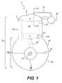
- Fig. 1 is a schematic illustration of an internal combustion engine of the present invention;
- Fig. 2A is a cross-section, taken through line A-A of Fig. 1, of a first embodiment of the cylinder head and blow-by gas ventilation system;
- Fig. 2B is a cross-section, taken through line A-A of Fig. 1, of a second embodiment of the cylinder head and blow-by gas ventilation system;
- Fig. 3 is a perspective view of the valve cover of the engine of Fig. 1 corresponding to the first embodiment;
- Fig. 4 is a side view of a motorcycle powered by the engine of Fig. 1; and
- Fig. 5 is a side view of an all-terrain vehicle (ATV) powered by the engine of Fig. 1 .
- As shown in Fig. 1, the internal combustion engine 1'; which is preferably a four-stroke engine, has an
engine casing 22. Theengine casing 22 is made of three main parts. These are thecrankcase 24, thecylinder block 30, and thevalve cover 3. Thevalve cover 3 can be separated from the remainder of theengine casing 22 along separatingplane 5, as discussed in more detail below. Alower portion 26 of thecrankcase 24 can also be separated a from the remainder of theengine casing 22 along separatingplane 32. Anupper portion 28 of thecrankcase 22 and the cylinder block 30 a preferably integrally formed, but it is contemplated that they could also be separable portions of the engine casing. - One or
more cylinders 42 are formed in thecylinder block 30. Each cylinder houses apiston 38. Acylinder head 4, which will be described in more detail below, is disposed at the upper portion of thecylinder block 30 and is covered by thevalve cover 3. Thecylinder head 4 and thevalve cover 3 together form a cylinder head assembly. Thecylinder 42,piston 38, andcylinder head 4 define together acombustion chamber 44. Theinduction system 50 fluidly communicates with thecombustion chamber 44 to provide the engine with the oxygen necessary to the combustion of the fuel inside thecombustion chamber 44. - The
piston 38 is connected to the crankshaft (not shown) of the engine 1 by a connectingrod 40. The crankshaft: is disposed in thecrankcase 24, preferably along the separatingplane 32, During operation of the engine 1, thepiston 38 reciprocates inside thecylinder 42 which causes the crankshaft to rotate. The crankshaft is operatively connected to or integrally formed with theoutput shaft 34. An end of theoutput shaft 34 extends externally of theengine casing 22. Anoutput wheel 36, in the form of a gear or sprocket, is disposed on the end of theoutput shaft 34 and is used to transmit power from the engine 1 to, for example, the wheels of a vehicle. - During operation of the engine 1, some of the gases produced by the combustion process occurring in the
combustion chamber 44 enter thecrankcase 24 by passing through thegap 46 between thepiston 38 and thecylinder 42. As explained above, these are known as blow-by gases and need to be returned to theinduction system 50. Thecrankcase 24 fluidly communicates with a blow-by gas ventilation system 2 (Figs. 2A, 2B) of the engine 1 via a passage 48 (Figs. 2A, 2B) in thecylinder block 30. - The
cylinder head 4 accommodates at least part of the valve operation mechanism which includes one or more of the following elements (which for clarity have not been specifically illustrated): valves, valve springs, rocker arms, barrel tappets, and cam followers. As can be seen in Fig. 2A, thevalve cover 3 is connected to thecylinder head 4 byfasteners 20, preferably screws. Acylinder head gasket 19 is disposed between thevalve cover 3 and thecylinder head 4 in order to seal the connection between these two parts. Acamshaft 6 is supported in thecylinder head 4 by camshaft bearings 8 for rotation about thecamshaft axis 9. Thecamshaft axis 9 is preferably disposed on the separatingplane 5. A plurality ofcams 7 are disposed on thecamshaft 6 and are used to actuate the valves (not shown) in thecylinder head 4. A drivingsprocket 10 is disposed at one end of thecamshaft 6. The drivingsprocket 10 is operatively connected to the crankshaft by a chain or a belt so as to rotate during operation of the engine 1. Thecamshaft 6 rotates together with the drivingsprocket 10. - A
separator wheel 12 is disposed at the other end of thecamshaft 6. Theseparator wheel 12 is secured to thecamshaft 6 by afastener 15, preferably a bolt, such that theseparator wheel 12 rotates together with the camshaft. Theseparator wheel 12 is preferably a gear or sprocket which is used to drive a secondary component of the engine 1, such as a water pump. Theseparator wheel 12 has afirst opening 13, asecond opening 14, and achannel 21 extending radially from thesecond opening 14 to thefirst opening 13 relative to thecamshaft axis 9. As can be seen, thechannel 21 is slightly angled relative to a line normal to thecamshaft axis 9. It can also be seen that thesecond opening 14 is disposed is coaxial with thecamshaft axis 9 and is located at an end of thecamshaft 6. It is contemplated that theseparator wheel 12 could be disposed on a different shaft and which would be driven by thecamshaft 6 or some other shaft of the engine 1. - A
suction tube 17 is fluidly connected to thesecond opening 14 of theseparator wheel 12. In the preferred embodiment illustrated, theopening 52 at the end of thesuction tube 17 is centered about thecamshaft axis 9. Thesuction tube 17 is preferably integrally formed with thevalve cover 3 as shown in Fig. 3. This can be achieved by casting these two elements as a single part. Alternatively, it is contemplated thatsuction tube 17 could be otherwise permanently affixed to thevalve cover 3 by welding, soldering, or bonding the two together for example. Agasket 16, in the form of a ring gasket, is disposed between theabutment surface 54 of thesuction tube 17 and thesecond opening 14 ofseparator wheel 12. Thegasket 16 seals the connection between therotating separator wheel 12 and thenon-rotating abutment surface 54 of thesuction tube 17. As can be seen in Fig. 2A, theabutment surface 54 of thesuction tube 17, the second opening of theseparator wheel 12, and thegasket 16 are all disposed on the separatingplane 5. As best seen in Fig. 3, theabutment surface 54 is of unitary construction which facilitates the positioning of thevalve cover 3 and improves sealing between theabutment surface 54 and thegasket 16. Thegasket 16 can be attached to either one of theabutment surface 54 and theseparator wheel 12, but is preferably attached to theseparator wheel 54 by clips. Thegasket 16 is preferably made of an oil resistant elastomer or plastic (thermoplastic or duroplast) or of metal. Thesuction tube 17 is connected to aline 18 connected at one end to thevalve cover 3 and, as seen in Fig. 1, to theinduction system 50 of the engine 1 at the other end. - Fig. 2B illustrates an alternative embodiment of the blow-by
gas ventilation system 2. In this embodiment, thesuction tube 17 is integrally formed with thecylinder head 4. Alternatively, it is contemplated thatsuction tube 17 could be otherwise permanently affixed to thecylinder head 4 by welding, soldering, or bonding the two together for example. All other elements are similar to those described above with respect to Fig. 2A, and as such have been numbered using the same reference numerals and will not be described again. It is contemplated that thesuction tube 17 could also be made integrally with or permanently affixed to other portions of theengine casing 22. For example, thesuction tube 17 could be affixed to a portion of thecrankcase 24 and extend upwardly so as to have itsopening 52 in alignment with thesecond opening 14 of theseparator wheel 12. - During operation of the engine 1, the crankshaft causes the driving
sprocket 10 to rotate, thereby causing thecamshaft 6 and theseparator wheel 12 to rotated with the drivingsprocket 10. The mixture of blow-by gases and oil droplets present in thecrankcase 24 move up thecylinder block 30 to thecylinder head 4 via thepassage 48. The mixture then enters thefirst opening 13 of therotating separator wheel 12. The rotation of theseparator wheel 12 causes the oil droplets to separate from the mixture and to exit thefirst opening 13 of theseparator wheel 12. The separated oil droplets then return to thecrankcase 24. The remaining blow-by gases continue through thechannel 21 of theseparator wheel 12, exit thesecond opening 14, pass through thegasket 16, and enter thesuction tube 17. The blow-by gases are then returned to theinduction system 50 of the engine 1 via theline 18. - It is contemplated that additional openings in fluid communication with the
channel 21 could be provided on theseparator wheel 12. These additional openings would be used by the separated oil droplets to exit theseparator wheel 12 to return to thecrankcase 24. - The internal combustion engine 1 could be used to power a
motorcycle 300, as shown in Fig. 4. Themotorcycle 300 has twowheels handlebar 304 to steer thefront wheel 302A, and a straddle-type seat 306. The engine 1 is mounted to theframe 308 of themotorcycle 300 below theseat 306. The engine 1 powers themotorcycle 300 by having theoutput shaft 34 operatively connected to therear wheel 302B by a via achain 310. - The internal combustion engine 1 could also be used to power an all-terrain vehicle (ATV) 350, as shown in Fig. 5. The
ATV 350 has twofront wheels 352A, tworear wheels 352B, ahandlebar 354 to steer the twofront wheels 352A, and a straddle-type seat 356. The engine 1 is mounted to the frame 358 of theATV 350 below theseat 356. The engine 1 powers theATV 350 by having the output shaft: 34 operatively connected to the tworear wheels 352B by a via achain 360. - It is contemplated that the internal combustion engine 1 described above could also be used to power other motorized recreational vehicle such as three-wheeled straddle-type vehicles, personal watercraft snowmobiles, sports boats, outboard and inboard marine engines, aircraft, karts, and small utility vehicles.
- Modifications and improvements to the above-described embodiments of the present invention may become apparent to those skilled in the art. The foregoing description is intended to be exemplary rather than limiting. The scope of the present invention is therefore intended to be limited solely by the scope of the appended claims.
Claims (20)
- An internal combustion engine (1) comprising:an engine casing (22) having a crankcase (24) and a separating plane (5) along which the engine casing can be separated;a shaft (6) disposed in the engine casing and having a shaft axis (9);at least one bearing (8) supporting the shaft in the engine casing and permitting rotation of the shaft about the shaft axis;a separator wheel (12) disposed on the shaft for rotation therewith, the separator wheel having a first opening (13) in fluid communication with the crankcase, a second opening (14), and a channel (21) extending radially from the second opening to the first opening relative to the shaft axis;a suction tube (17) fluidly communicating with the second opening of the separator wheel, the suction tube being permanently affixed to a portion of the engine casing, an end of the suction tube having a unitary abutment surface (54); anda gasket (16) disposed between the unitary abutment surface of the suction tube and the second opening of the separator wheel, the gasket being also disposed at least in part on the separating plane of the engine casing.
- The engine of claim 1, wherein the suction tube is cast with the engine casing.
- The engine of claims 1 or 2, wherein the second opening is coaxial with the shaft axis.
- The engine of any one of claims 1 to 3, wherein the gasket is a ring gasket.
- The engine of any one of claims 1 to 4, wherein the engine casing has a cylinder head (4) and a valve cover (3); and
wherein the shaft is disposed in the cylinder head. - The engine of claim 5, wherein the valve cover separates from the cylinder head along the separating plane.
- The engine of claim 6, wherein the suction tube is integrally formed with the valve cover.
- The engine of claim 6, wherein the suction tube is integrally formed with the cylinder head.
- The engine of any one of claims 1 to 8, wherein the shaft is a camshaft; and
further comprising at least one cam (7) on the camshaft for actuating a valve disposed in the cylinder head. - The engine of claim 9, wherein the separator wheel is disposed at a first end of the camshaft.
- The engine of claim 10, further comprising a driving sprocket (10) provided at a second end of the camshaft for driving the camshaft.
- The engine of any one of claims 1 to 11, wherein the separator wheel is a driving sprocket for driving a secondary component.
- The engine of an one of claims 1 to 11, wherein the separator wheel is a gear.
- The engine of any one of claims 1 to 13, wherein the suction tube is disposed at least in part on the separating plane of the engine casing.
- The engine of any one of claims 1 to 14, wherein, when the engine is in operation, a mixture of oil droplets and blow-by gases present in the crankcase enters the first opening of the separator wheel, rotation of the separator wheel causes the oil droplets to separate from the mixture, the separated oil droplets exit the first opening of the separator wheel and return to the crankcase, the remaining blow-by gases continue through the channel of the separator wheel, exit the second opening, pass through the gasket, and enter the suction tube, the blow-by gases are then returned to an induction system (50) of the engine.
- A cylinder head assembly comprising:a cylinder head (4);a valve cover (3) disposed on the cylinder head;a separating plane (5) along which the valve cover can be separated from the cylinder head;a camshaft (6) disposed in the cylinder head and having a camshaft axis (9);at least one bearing (8) supporting the camshaft in the cylinder head and permitting rotation of the camshaft about the camshaft axis;a separator wheel (12) disposed on the camshaft for rotation therewith, the separator wheel having a first opening (13), a second opening (14), and a channel (21) extending radially from the second opening to the first opening relative to the camshaft axis;a suction tube (17) fluidly communicating with the second opening of the separator wheel, the suction tube being permanently affixed to the valve cover, an end of the suction tube having a unitary abutment surface (54); anda gasket (16) disposed between the unitary abutment surface of the suction tube and the second opening of the separator wheel, the gasket being also disposed at least in part on the separating plane of the engine casing.
- The cylinder head assembly of claim 16, wherein the second opening is coaxial with the camshaft axis.
- The cylinder head assembly of claims 16 or 17, wherein the suction tube is integrally formed with the valve cover.
- The cylinder head assembly of any one of claims 16 to 18, wherein the separator wheel is disposed at a first end of the camshaft.
- The cylinder head assembly of claim 19, further comprising a driving sprocket (10) provided at a second end of the camshaft for driving the camshaft.
Priority Applications (1)
| Application Number | Priority Date | Filing Date | Title |
|---|---|---|---|
| EP20060124079 EP1785601B1 (en) | 2005-11-14 | 2006-11-14 | Internal Combustion Engine Blow-By Gas Ventilation System |
Applications Claiming Priority (2)
| Application Number | Priority Date | Filing Date | Title |
|---|---|---|---|
| EP05110707 | 2005-11-14 | ||
| EP20060124079 EP1785601B1 (en) | 2005-11-14 | 2006-11-14 | Internal Combustion Engine Blow-By Gas Ventilation System |
Publications (2)
| Publication Number | Publication Date |
|---|---|
| EP1785601A1 true EP1785601A1 (en) | 2007-05-16 |
| EP1785601B1 EP1785601B1 (en) | 2012-10-24 |
Family
ID=36263777
Family Applications (1)
| Application Number | Title | Priority Date | Filing Date |
|---|---|---|---|
| EP20060124079 Active EP1785601B1 (en) | 2005-11-14 | 2006-11-14 | Internal Combustion Engine Blow-By Gas Ventilation System |
Country Status (1)
| Country | Link |
|---|---|
| EP (1) | EP1785601B1 (en) |
Cited By (4)
| Publication number | Priority date | Publication date | Assignee | Title |
|---|---|---|---|---|
| CN102444446A (en) * | 2010-09-30 | 2012-05-09 | 富士重工业株式会社 | Breather apparatus for engine |
| CN107084017A (en) * | 2017-06-21 | 2017-08-22 | 浙江春风动力股份有限公司 | Vehicle and its engine |
| EP3929412A1 (en) * | 2020-06-24 | 2021-12-29 | RENAULT s.a.s. | Assembly comprising a cam shaft and an oil separator by centrifugation supported by said shaft |
| CN115288875A (en) * | 2022-10-10 | 2022-11-04 | 泗洪亿成机械制造有限公司 | Sealed crankcase of oil-free piston |
Citations (5)
| Publication number | Priority date | Publication date | Assignee | Title |
|---|---|---|---|---|
| US4651704A (en) * | 1985-01-30 | 1987-03-24 | Honda Giken Kogyo Kabushiki Kaisha | Breather arrangement for cam case of internal combustion engine |
| US5261380A (en) | 1992-07-15 | 1993-11-16 | Ford Motor Company | Crankcase ventilation system for automotive engine |
| DE4237128A1 (en) | 1992-11-03 | 1994-01-27 | Bayerische Motoren Werke Ag | Crankcase vent with centrifuge for oil sepn. - has peripheral centrifugal inlets for blow-by gases |
| US5542402A (en) * | 1995-04-05 | 1996-08-06 | Ford Motor Company | Positive crankcase ventilation system with a centrifugal oil separator |
| DE19608503A1 (en) | 1996-03-05 | 1997-09-11 | Bayerische Motoren Werke Ag | Crankcase venting for internal combustion engine |
-
2006
- 2006-11-14 EP EP20060124079 patent/EP1785601B1/en active Active
Patent Citations (5)
| Publication number | Priority date | Publication date | Assignee | Title |
|---|---|---|---|---|
| US4651704A (en) * | 1985-01-30 | 1987-03-24 | Honda Giken Kogyo Kabushiki Kaisha | Breather arrangement for cam case of internal combustion engine |
| US5261380A (en) | 1992-07-15 | 1993-11-16 | Ford Motor Company | Crankcase ventilation system for automotive engine |
| DE4237128A1 (en) | 1992-11-03 | 1994-01-27 | Bayerische Motoren Werke Ag | Crankcase vent with centrifuge for oil sepn. - has peripheral centrifugal inlets for blow-by gases |
| US5542402A (en) * | 1995-04-05 | 1996-08-06 | Ford Motor Company | Positive crankcase ventilation system with a centrifugal oil separator |
| DE19608503A1 (en) | 1996-03-05 | 1997-09-11 | Bayerische Motoren Werke Ag | Crankcase venting for internal combustion engine |
Cited By (6)
| Publication number | Priority date | Publication date | Assignee | Title |
|---|---|---|---|---|
| CN102444446A (en) * | 2010-09-30 | 2012-05-09 | 富士重工业株式会社 | Breather apparatus for engine |
| CN107084017A (en) * | 2017-06-21 | 2017-08-22 | 浙江春风动力股份有限公司 | Vehicle and its engine |
| CN107084017B (en) * | 2017-06-21 | 2023-01-31 | 浙江春风动力股份有限公司 | Vehicle and engine thereof |
| EP3929412A1 (en) * | 2020-06-24 | 2021-12-29 | RENAULT s.a.s. | Assembly comprising a cam shaft and an oil separator by centrifugation supported by said shaft |
| FR3111943A1 (en) * | 2020-06-24 | 2021-12-31 | Renault Sas | ASSEMBLY CONTAINING ONE CAMSHAFT AND ONE OIL SEPARATOR PER CENTRIFUGATION CARRIED BY THIS SHAFT |
| CN115288875A (en) * | 2022-10-10 | 2022-11-04 | 泗洪亿成机械制造有限公司 | Sealed crankcase of oil-free piston |
Also Published As
| Publication number | Publication date |
|---|---|
| EP1785601B1 (en) | 2012-10-24 |
Similar Documents
| Publication | Publication Date | Title |
|---|---|---|
| US7455057B2 (en) | Internal combustion engine blow-by gas ventilation system | |
| US6390869B2 (en) | Four stroke engine with valve train arrangement | |
| US8919321B2 (en) | Internal combustion engine with lubrication system | |
| EP1228956B1 (en) | Engine for motorcycles | |
| JP4698623B2 (en) | Breather device for internal combustion engine | |
| JP2001289295A (en) | V-belt type transmission | |
| US7069895B2 (en) | Air intake system of outboard motor | |
| US7325527B2 (en) | Oil pump arrangement for an internal combustion engine | |
| EP1785601A1 (en) | Internal Combustion Engine Blow-By Gas Ventilation System | |
| US6192865B1 (en) | Fuel injection apparatus for vehicular engine | |
| US7263958B2 (en) | Valve drive mechanism in an internal combustion engine | |
| EP1785611B1 (en) | Oil pump arrangement for an internal combustion engine | |
| JP2002235548A (en) | Parallel four cylinder engine | |
| CA2586366C (en) | Lubricating apparatus for internal combustion engine | |
| JPH11182260A (en) | Motorcycle | |
| JP5205117B2 (en) | Engine and vehicle equipped with the engine | |
| US6209505B1 (en) | Four-cycle engine for vehicle | |
| US20240309819A1 (en) | Power unit | |
| EP1378635B1 (en) | Assembly opening portion closing structure in engine | |
| WO2001021940A1 (en) | Vertical engine | |
| JP3334503B2 (en) | Outboard engine | |
| JP2002213216A (en) | Parallel four cylinder engine | |
| JPH0633725A (en) | Oil pan baffle construction for outboard motor | |
| JP2002206428A (en) | Water-cooled parallel four-stroke cycle engine | |
| JP2002201925A (en) | Engine |
Legal Events
| Date | Code | Title | Description |
|---|---|---|---|
| PUAI | Public reference made under article 153(3) epc to a published international application that has entered the european phase |
Free format text: ORIGINAL CODE: 0009012 |
|
| AK | Designated contracting states |
Kind code of ref document: A1 Designated state(s): AT BE BG CH CY CZ DE DK EE ES FI FR GB GR HU IE IS IT LI LT LU LV MC NL PL PT RO SE SI SK TR |
|
| AX | Request for extension of the european patent |
Extension state: AL BA HR MK YU |
|
| 17P | Request for examination filed |
Effective date: 20070910 |
|
| 17Q | First examination report despatched |
Effective date: 20071023 |
|
| AKX | Designation fees paid |
Designated state(s): AT BE BG CH CY CZ DE DK EE ES FI FR GB GR HU IE IS IT LI LT LU LV MC NL PL PT RO SE SI SK TR |
|
| RAP1 | Party data changed (applicant data changed or rights of an application transferred) |
Owner name: BRP-POWERTRAIN GMBH & CO. KG |
|
| GRAP | Despatch of communication of intention to grant a patent |
Free format text: ORIGINAL CODE: EPIDOSNIGR1 |
|
| GRAS | Grant fee paid |
Free format text: ORIGINAL CODE: EPIDOSNIGR3 |
|
| GRAA | (expected) grant |
Free format text: ORIGINAL CODE: 0009210 |
|
| AK | Designated contracting states |
Kind code of ref document: B1 Designated state(s): AT BE BG CH CY CZ DE DK EE ES FI FR GB GR HU IE IS IT LI LT LU LV MC NL PL PT RO SE SI SK TR |
|
| REG | Reference to a national code |
Ref country code: GB Ref legal event code: FG4D Ref country code: DE Ref legal event code: R081 Ref document number: 602006032597 Country of ref document: DE Owner name: BRP-ROTAX GMBH & CO. KG, AT Free format text: FORMER OWNER: BRP-ROTAX GMBH & CO. KG, GUNSKIRCHEN, AT |
|
| REG | Reference to a national code |
Ref country code: CH Ref legal event code: EP |
|
| REG | Reference to a national code |
Ref country code: AT Ref legal event code: REF Ref document number: 581079 Country of ref document: AT Kind code of ref document: T Effective date: 20121115 |
|
| REG | Reference to a national code |
Ref country code: IE Ref legal event code: FG4D |
|
| REG | Reference to a national code |
Ref country code: DE Ref legal event code: R096 Ref document number: 602006032597 Country of ref document: DE Effective date: 20121227 |
|
| REG | Reference to a national code |
Ref country code: NL Ref legal event code: VDEP Effective date: 20121024 |
|
| PG25 | Lapsed in a contracting state [announced via postgrant information from national office to epo] |
Ref country code: FI Free format text: LAPSE BECAUSE OF FAILURE TO SUBMIT A TRANSLATION OF THE DESCRIPTION OR TO PAY THE FEE WITHIN THE PRESCRIBED TIME-LIMIT Effective date: 20121024 Ref country code: NL Free format text: LAPSE BECAUSE OF FAILURE TO SUBMIT A TRANSLATION OF THE DESCRIPTION OR TO PAY THE FEE WITHIN THE PRESCRIBED TIME-LIMIT Effective date: 20121024 Ref country code: SE Free format text: LAPSE BECAUSE OF FAILURE TO SUBMIT A TRANSLATION OF THE DESCRIPTION OR TO PAY THE FEE WITHIN THE PRESCRIBED TIME-LIMIT Effective date: 20121024 Ref country code: IS Free format text: LAPSE BECAUSE OF FAILURE TO SUBMIT A TRANSLATION OF THE DESCRIPTION OR TO PAY THE FEE WITHIN THE PRESCRIBED TIME-LIMIT Effective date: 20130224 |
|
| PG25 | Lapsed in a contracting state [announced via postgrant information from national office to epo] |
Ref country code: CY Free format text: LAPSE BECAUSE OF FAILURE TO SUBMIT A TRANSLATION OF THE DESCRIPTION OR TO PAY THE FEE WITHIN THE PRESCRIBED TIME-LIMIT Effective date: 20121024 Ref country code: LV Free format text: LAPSE BECAUSE OF FAILURE TO SUBMIT A TRANSLATION OF THE DESCRIPTION OR TO PAY THE FEE WITHIN THE PRESCRIBED TIME-LIMIT Effective date: 20121024 Ref country code: PL Free format text: LAPSE BECAUSE OF FAILURE TO SUBMIT A TRANSLATION OF THE DESCRIPTION OR TO PAY THE FEE WITHIN THE PRESCRIBED TIME-LIMIT Effective date: 20121024 Ref country code: PT Free format text: LAPSE BECAUSE OF FAILURE TO SUBMIT A TRANSLATION OF THE DESCRIPTION OR TO PAY THE FEE WITHIN THE PRESCRIBED TIME-LIMIT Effective date: 20130225 Ref country code: BE Free format text: LAPSE BECAUSE OF FAILURE TO SUBMIT A TRANSLATION OF THE DESCRIPTION OR TO PAY THE FEE WITHIN THE PRESCRIBED TIME-LIMIT Effective date: 20121024 Ref country code: GR Free format text: LAPSE BECAUSE OF FAILURE TO SUBMIT A TRANSLATION OF THE DESCRIPTION OR TO PAY THE FEE WITHIN THE PRESCRIBED TIME-LIMIT Effective date: 20130125 Ref country code: SI Free format text: LAPSE BECAUSE OF FAILURE TO SUBMIT A TRANSLATION OF THE DESCRIPTION OR TO PAY THE FEE WITHIN THE PRESCRIBED TIME-LIMIT Effective date: 20121024 |
|
| REG | Reference to a national code |
Ref country code: CH Ref legal event code: PL |
|
| PG25 | Lapsed in a contracting state [announced via postgrant information from national office to epo] |
Ref country code: BG Free format text: LAPSE BECAUSE OF FAILURE TO SUBMIT A TRANSLATION OF THE DESCRIPTION OR TO PAY THE FEE WITHIN THE PRESCRIBED TIME-LIMIT Effective date: 20130124 Ref country code: CH Free format text: LAPSE BECAUSE OF NON-PAYMENT OF DUE FEES Effective date: 20121130 Ref country code: EE Free format text: LAPSE BECAUSE OF FAILURE TO SUBMIT A TRANSLATION OF THE DESCRIPTION OR TO PAY THE FEE WITHIN THE PRESCRIBED TIME-LIMIT Effective date: 20121024 Ref country code: LI Free format text: LAPSE BECAUSE OF NON-PAYMENT OF DUE FEES Effective date: 20121130 Ref country code: CZ Free format text: LAPSE BECAUSE OF FAILURE TO SUBMIT A TRANSLATION OF THE DESCRIPTION OR TO PAY THE FEE WITHIN THE PRESCRIBED TIME-LIMIT Effective date: 20121024 Ref country code: DK Free format text: LAPSE BECAUSE OF FAILURE TO SUBMIT A TRANSLATION OF THE DESCRIPTION OR TO PAY THE FEE WITHIN THE PRESCRIBED TIME-LIMIT Effective date: 20121024 Ref country code: SK Free format text: LAPSE BECAUSE OF FAILURE TO SUBMIT A TRANSLATION OF THE DESCRIPTION OR TO PAY THE FEE WITHIN THE PRESCRIBED TIME-LIMIT Effective date: 20121024 |
|
| REG | Reference to a national code |
Ref country code: IE Ref legal event code: MM4A |
|
| PG25 | Lapsed in a contracting state [announced via postgrant information from national office to epo] |
Ref country code: RO Free format text: LAPSE BECAUSE OF FAILURE TO SUBMIT A TRANSLATION OF THE DESCRIPTION OR TO PAY THE FEE WITHIN THE PRESCRIBED TIME-LIMIT Effective date: 20121024 |
|
| PLBE | No opposition filed within time limit |
Free format text: ORIGINAL CODE: 0009261 |
|
| STAA | Information on the status of an ep patent application or granted ep patent |
Free format text: STATUS: NO OPPOSITION FILED WITHIN TIME LIMIT |
|
| GBPC | Gb: european patent ceased through non-payment of renewal fee |
Effective date: 20130124 |
|
| REG | Reference to a national code |
Ref country code: FR Ref legal event code: ST Effective date: 20130731 |
|
| 26N | No opposition filed |
Effective date: 20130725 |
|
| PG25 | Lapsed in a contracting state [announced via postgrant information from national office to epo] |
Ref country code: IE Free format text: LAPSE BECAUSE OF NON-PAYMENT OF DUE FEES Effective date: 20121114 Ref country code: ES Free format text: LAPSE BECAUSE OF FAILURE TO SUBMIT A TRANSLATION OF THE DESCRIPTION OR TO PAY THE FEE WITHIN THE PRESCRIBED TIME-LIMIT Effective date: 20130204 |
|
| REG | Reference to a national code |
Ref country code: DE Ref legal event code: R097 Ref document number: 602006032597 Country of ref document: DE Effective date: 20130725 |
|
| PG25 | Lapsed in a contracting state [announced via postgrant information from national office to epo] |
Ref country code: GB Free format text: LAPSE BECAUSE OF NON-PAYMENT OF DUE FEES Effective date: 20130124 Ref country code: FR Free format text: LAPSE BECAUSE OF NON-PAYMENT OF DUE FEES Effective date: 20121226 |
|
| PG25 | Lapsed in a contracting state [announced via postgrant information from national office to epo] |
Ref country code: MC Free format text: LAPSE BECAUSE OF NON-PAYMENT OF DUE FEES Effective date: 20121130 Ref country code: TR Free format text: LAPSE BECAUSE OF FAILURE TO SUBMIT A TRANSLATION OF THE DESCRIPTION OR TO PAY THE FEE WITHIN THE PRESCRIBED TIME-LIMIT Effective date: 20121024 |
|
| PG25 | Lapsed in a contracting state [announced via postgrant information from national office to epo] |
Ref country code: LU Free format text: LAPSE BECAUSE OF NON-PAYMENT OF DUE FEES Effective date: 20121114 |
|
| PG25 | Lapsed in a contracting state [announced via postgrant information from national office to epo] |
Ref country code: HU Free format text: LAPSE BECAUSE OF FAILURE TO SUBMIT A TRANSLATION OF THE DESCRIPTION OR TO PAY THE FEE WITHIN THE PRESCRIBED TIME-LIMIT Effective date: 20061114 Ref country code: LT Free format text: LAPSE BECAUSE OF FAILURE TO SUBMIT A TRANSLATION OF THE DESCRIPTION OR TO PAY THE FEE WITHIN THE PRESCRIBED TIME-LIMIT Effective date: 20121024 |
|
| REG | Reference to a national code |
Ref country code: AT Ref legal event code: HC Ref document number: 581079 Country of ref document: AT Kind code of ref document: T Owner name: BRP-ROTAX GMBH & CO KG, AT Effective date: 20160902 |
|
| REG | Reference to a national code |
Ref country code: DE Ref legal event code: R082 Ref document number: 602006032597 Country of ref document: DE Representative=s name: PATENT- UND RECHTSANWAELTE DR. SOLF & ZAPF, DE Ref country code: DE Ref legal event code: R081 Ref document number: 602006032597 Country of ref document: DE Owner name: BRP-ROTAX GMBH & CO. KG, AT Free format text: FORMER OWNER: BRP-POWERTRAIN GMBH & CO.KG., GUNSKIRCHEN, AT Ref country code: DE Ref legal event code: R082 Ref document number: 602006032597 Country of ref document: DE Representative=s name: DR. SOLF & ZAPF PATENT- UND RECHTSANWAELTE, DE Ref country code: DE Ref legal event code: R082 Ref document number: 602006032597 Country of ref document: DE Representative=s name: DR. SOLF & ZAPF PATENT- UND RECHTSANWALTS PART, DE |
|
| PGFP | Annual fee paid to national office [announced via postgrant information from national office to epo] |
Ref country code: IT Payment date: 20231019 Year of fee payment: 18 Ref country code: DE Payment date: 20231019 Year of fee payment: 18 Ref country code: AT Payment date: 20231023 Year of fee payment: 18 |