EP1785401A1 - Silica vessel with nozzle and method of making - Google Patents
Silica vessel with nozzle and method of making Download PDFInfo
- Publication number
- EP1785401A1 EP1785401A1 EP06123350A EP06123350A EP1785401A1 EP 1785401 A1 EP1785401 A1 EP 1785401A1 EP 06123350 A EP06123350 A EP 06123350A EP 06123350 A EP06123350 A EP 06123350A EP 1785401 A1 EP1785401 A1 EP 1785401A1
- Authority
- EP
- European Patent Office
- Prior art keywords
- crucible
- mold
- silica
- grain
- plug
- Prior art date
- Legal status (The legal status is an assumption and is not a legal conclusion. Google has not performed a legal analysis and makes no representation as to the accuracy of the status listed.)
- Granted
Links
- VYPSYNLAJGMNEJ-UHFFFAOYSA-N Silicium dioxide Chemical compound O=[Si]=O VYPSYNLAJGMNEJ-UHFFFAOYSA-N 0.000 title claims abstract description 97
- 239000000377 silicon dioxide Substances 0.000 title claims abstract description 39
- 238000004519 manufacturing process Methods 0.000 title 1
- 239000005350 fused silica glass Substances 0.000 claims abstract description 6
- 238000000034 method Methods 0.000 claims description 16
- 239000011521 glass Substances 0.000 claims description 12
- 238000010438 heat treatment Methods 0.000 claims description 4
- 230000015572 biosynthetic process Effects 0.000 claims description 2
- 239000012530 fluid Substances 0.000 claims 1
- OKTJSMMVPCPJKN-UHFFFAOYSA-N Carbon Chemical compound [C] OKTJSMMVPCPJKN-UHFFFAOYSA-N 0.000 abstract description 13
- 239000010439 graphite Substances 0.000 abstract description 13
- 229910002804 graphite Inorganic materials 0.000 abstract description 13
- 230000004927 fusion Effects 0.000 abstract description 11
- XUIMIQQOPSSXEZ-UHFFFAOYSA-N Silicon Chemical compound [Si] XUIMIQQOPSSXEZ-UHFFFAOYSA-N 0.000 description 3
- 238000005336 cracking Methods 0.000 description 3
- 239000012535 impurity Substances 0.000 description 3
- 229910052710 silicon Inorganic materials 0.000 description 3
- 239000010703 silicon Substances 0.000 description 3
- 238000000137 annealing Methods 0.000 description 2
- 238000007599 discharging Methods 0.000 description 2
- 239000007788 liquid Substances 0.000 description 2
- 230000009286 beneficial effect Effects 0.000 description 1
- 238000007796 conventional method Methods 0.000 description 1
- 239000013078 crystal Substances 0.000 description 1
- 229910003460 diamond Inorganic materials 0.000 description 1
- 239000010432 diamond Substances 0.000 description 1
- 239000012212 insulator Substances 0.000 description 1
- 238000012986 modification Methods 0.000 description 1
- 230000004048 modification Effects 0.000 description 1
- 239000006060 molten glass Substances 0.000 description 1
- 229910021420 polycrystalline silicon Inorganic materials 0.000 description 1
- 239000010453 quartz Substances 0.000 description 1
- 239000004065 semiconductor Substances 0.000 description 1
- 238000007493 shaping process Methods 0.000 description 1
- 239000007787 solid Substances 0.000 description 1
Images



Classifications
-
- B—PERFORMING OPERATIONS; TRANSPORTING
- B28—WORKING CEMENT, CLAY, OR STONE
- B28B—SHAPING CLAY OR OTHER CERAMIC COMPOSITIONS; SHAPING SLAG; SHAPING MIXTURES CONTAINING CEMENTITIOUS MATERIAL, e.g. PLASTER
- B28B1/00—Producing shaped prefabricated articles from the material
- B28B1/20—Producing shaped prefabricated articles from the material by centrifugal or rotational casting
-
- C—CHEMISTRY; METALLURGY
- C03—GLASS; MINERAL OR SLAG WOOL
- C03B—MANUFACTURE, SHAPING, OR SUPPLEMENTARY PROCESSES
- C03B19/00—Other methods of shaping glass
- C03B19/09—Other methods of shaping glass by fusing powdered glass in a shaping mould
- C03B19/095—Other methods of shaping glass by fusing powdered glass in a shaping mould by centrifuging, e.g. arc discharge in rotating mould
-
- B—PERFORMING OPERATIONS; TRANSPORTING
- B28—WORKING CEMENT, CLAY, OR STONE
- B28B—SHAPING CLAY OR OTHER CERAMIC COMPOSITIONS; SHAPING SLAG; SHAPING MIXTURES CONTAINING CEMENTITIOUS MATERIAL, e.g. PLASTER
- B28B1/00—Producing shaped prefabricated articles from the material
- B28B1/26—Producing shaped prefabricated articles from the material by slip-casting, i.e. by casting a suspension or dispersion of the material in a liquid-absorbent or porous mould, the liquid being allowed to soak into or pass through the walls of the mould; Moulds therefor ; specially for manufacturing articles starting from a ceramic slip; Moulds therefor
- B28B1/28—Producing shaped prefabricated articles from the material by slip-casting, i.e. by casting a suspension or dispersion of the material in a liquid-absorbent or porous mould, the liquid being allowed to soak into or pass through the walls of the mould; Moulds therefor ; specially for manufacturing articles starting from a ceramic slip; Moulds therefor involving rotation of the mould about a centrifugal axis
-
- C—CHEMISTRY; METALLURGY
- C04—CEMENTS; CONCRETE; ARTIFICIAL STONE; CERAMICS; REFRACTORIES
- C04B—LIME, MAGNESIA; SLAG; CEMENTS; COMPOSITIONS THEREOF, e.g. MORTARS, CONCRETE OR LIKE BUILDING MATERIALS; ARTIFICIAL STONE; CERAMICS; REFRACTORIES; TREATMENT OF NATURAL STONE
- C04B35/00—Shaped ceramic products characterised by their composition; Ceramics compositions; Processing powders of inorganic compounds preparatory to the manufacturing of ceramic products
- C04B35/01—Shaped ceramic products characterised by their composition; Ceramics compositions; Processing powders of inorganic compounds preparatory to the manufacturing of ceramic products based on oxide ceramics
- C04B35/14—Shaped ceramic products characterised by their composition; Ceramics compositions; Processing powders of inorganic compounds preparatory to the manufacturing of ceramic products based on oxide ceramics based on silica
-
- C—CHEMISTRY; METALLURGY
- C30—CRYSTAL GROWTH
- C30B—SINGLE-CRYSTAL GROWTH; UNIDIRECTIONAL SOLIDIFICATION OF EUTECTIC MATERIAL OR UNIDIRECTIONAL DEMIXING OF EUTECTOID MATERIAL; REFINING BY ZONE-MELTING OF MATERIAL; PRODUCTION OF A HOMOGENEOUS POLYCRYSTALLINE MATERIAL WITH DEFINED STRUCTURE; SINGLE CRYSTALS OR HOMOGENEOUS POLYCRYSTALLINE MATERIAL WITH DEFINED STRUCTURE; AFTER-TREATMENT OF SINGLE CRYSTALS OR A HOMOGENEOUS POLYCRYSTALLINE MATERIAL WITH DEFINED STRUCTURE; APPARATUS THEREFOR
- C30B11/00—Single-crystal growth by normal freezing or freezing under temperature gradient, e.g. Bridgman-Stockbarger method
- C30B11/002—Crucibles or containers for supporting the melt
-
- C—CHEMISTRY; METALLURGY
- C30—CRYSTAL GROWTH
- C30B—SINGLE-CRYSTAL GROWTH; UNIDIRECTIONAL SOLIDIFICATION OF EUTECTIC MATERIAL OR UNIDIRECTIONAL DEMIXING OF EUTECTOID MATERIAL; REFINING BY ZONE-MELTING OF MATERIAL; PRODUCTION OF A HOMOGENEOUS POLYCRYSTALLINE MATERIAL WITH DEFINED STRUCTURE; SINGLE CRYSTALS OR HOMOGENEOUS POLYCRYSTALLINE MATERIAL WITH DEFINED STRUCTURE; AFTER-TREATMENT OF SINGLE CRYSTALS OR A HOMOGENEOUS POLYCRYSTALLINE MATERIAL WITH DEFINED STRUCTURE; APPARATUS THEREFOR
- C30B15/00—Single-crystal growth by pulling from a melt, e.g. Czochralski method
- C30B15/10—Crucibles or containers for supporting the melt
Definitions
- the present invention relates generally to fused silica vessels and more particularly to such vessels that include a nozzle for discharging liquid from the vessel.
- Such crucibles may be used, e.g., to melt metallic silicon, from which a single crystal ingot may be drawn. These ingots are sliced to provide the silicon wafer on which semiconductor circuits are formed.
- fused silica crucibles are used to melt metallic silicon, which is then poured into a mold to create a polycrystalline silicon ingot. Poured ingots are sliced to make solar cells.
- the crucible must include a nozzle in applications that require pouring.
- Prior art nozzles are formed on crucibles by first making the crucible as described above. After the crucible is formed and cooled, a diamond drill is used to drill a hole through a wall thereof, typically in the center of the bottom of the crucible. A preformed quartz glass nozzle is then welded to the crucible over the hole, thus providing a crucible from which liquid may be discharged via the nozzle.
- the system includes a mold 12 having a generally continuous smooth surface 14.
- Mold surface 14 includes a recess 16, also referred to herein as a discontinuity.
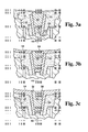
- recess 16 For a more detailed view of recess 16, attention is directed to FIG. 3A.
- the recess includes first and second sloped annular wall surfaces 18, 20, respectively.
- the lower portion of wall surface 18 is connected to the upper portion of wall surface 20 via a substantially horizontal annular floor surface 22.
- Another substantially horizontal floor surface 24 forms the lowermost portion of recess 16.
- a stud 26 comprises an upright cylindrical portion that extends upwardly from the lowermost portion of recess 16.
- a plurality of air channels like air channels 28, 30 communicate with inner mold surface 14.
- Each air channel comprises a cylindrical bore that creates a circular opening (not visible) on mold surface 14.
- Each air channel includes a porous graphite plug (also not visible) that prevents silica from being drawn from the mold cavity into the air channels.
- the air channels communicate with manifolds, like manifolds 32, 34, 36, which in turn communicate with a bore 38.
- a pump (not visible in the drawings) is connected to bore 38. The pump is configured to draw air from the mold cavity via the air channels and ultimately through bore 38 and out of system 10.
- Mold 12 may be rotated by a motor (not shown) about a vertical axis 40.
- a set of conventional electrodes 42, 44 is vertically movable into and out of the mold interior.
- the electrodes are connected to a conventional DC power supply 46 that can apply power to the electrodes in a selectable range between about 300 KVA and 1200 KVA.
- an extremely hot plasma gas ball 48(in FIG. 2) forms around the electrodes.
- tube 50 is inserted into recess 16.
- tube 50 has a frusto-conical (truncated-cone) exterior shape. Stud 26 is received into the lower end of tube 50, which stabilizes the tube.
- tube 50 may be prepared using conventional methods, such as being cut from a block, heat-formed from a pipe, or slip cast-although any technique to make a tube similar to tube 50 may be used.
- a frusto-conically shaped graphite plug 52 is inserted in the upper end of tube 50.
- plug 52 keeps quartz grain out of the interior of the tube during fusion.
- mold 12 along with tube 50 and plug 52, begin rotation about axis 40 while silica grain 54 (FIG. 1) is poured into the mold and formed into a crucible shape, as shown in FIG. 1.
- silica grain 54 FIG. 1
- Silica grain is added until both tube 50 and plug 52 are covered with grain as shown in FIG. 3A. As will shortly be explained, it is desirable to cover the graphite plug.
- the depth of silica grain over the plug may be in the range of 1 to 15mm, but preferably is in the range of 2-6 mm.
- a plasma gas ball 48 as shown in FIG. 2. This heats the silica grain and begins fusing it starting from its exposed surface toward mold surface 14.
- a layer of quartz glass 54 forms as a result of fusion of some of the silica grain. Fusion of the grains over plug 52 forms a thin layer of quartz glass 56 over the plug. This layer seals the graphite plug from the plasma gas ball and thus prevents the plug from burning and discharging impurities that might affect the quality of the fused glass around it. This is also why using relatively pure graphite to make the plug is important: the fewer the impurities in the plug, the fewer there are to be discharged into the surrounding grain and glass as heat is applied.
- FIG. 3C The progression of the fusion front can be observed from FIG. 3B, to FIG. 3C, to FIG. 3D, the latter depicting a substantially complete crucible.
- glass layer 56 begins to recede from the top of plug 52 until the top surface of the plug is exposed as shown in FIG. 3D.
- Glass layer 56 recedes as shown because the molten glass flows and also apparently because of the balance of surface tension and viscosity of molten silica.
- the molten silica forms around and to tube 50, which produces the structure of FIG. 3D, in which the crucible is fully fused.
- walls 18, 20 and floors 22, 24 are shaped to hold a substantially thicker layer of grain than, e.g., the layer that is between mold surface 14 and the outer layer of the fused crucible.
- This thick layer is beneficial because of the difference in the thermal expansion coefficients of silica glass and graphite. Because graphite contracts much more rapidly than silica glass as they cool, the grain acts as a cushion to absorb the pressure applied by the graphite mold as it contracts.
- the silica grain acts as an insulator during fusion: it insulates mold 12 from the heat of the plasma gas ball. In other words it traps the heat around tube 50 and the surrounding silica grain during fusion. This assists in forming the tube to the finished crucible as depicted in FIG. 3D.
- FIGs. 4A and 4B another implementation is depicted. This approach is substantially identical to that previously described except that plug 52 extends above the level of the silica grain after the grain is poured into the molds and shaped to form the crucible. This can be clearly seen in FIG. 4A.
- FIG. 4B depicts the grain after the crucible is fully fused.
- Such bubbles may have a diameter of 1 mm. While these bubbles may be acceptable in some applications, they are not desirable.
- a silica glass tapered nozzle 55 mm in length is created by cutting the piece from a silica glass block.
- a vessel having a 555 mm outer diameter and a 12 mm thick wall was formed as described above. This successfully fused the preformed nozzle to the vessel body with no cracking and without subsequent annealing. The resulting structure is used as a funnel to pour silica melt into a mold.
- Another vessel having a 610 mm outer diameter and 12 mm wall thickness was successfully formed in accordance with this system. It has a cylindrical nozzle having a 30 mm outer diameter, a 16 mm inner diameter, and a 65 mm length.
Landscapes
- Chemical & Material Sciences (AREA)
- Engineering & Computer Science (AREA)
- Organic Chemistry (AREA)
- Materials Engineering (AREA)
- Manufacturing & Machinery (AREA)
- Ceramic Engineering (AREA)
- Metallurgy (AREA)
- Crystallography & Structural Chemistry (AREA)
- Mechanical Engineering (AREA)
- Structural Engineering (AREA)
- Dispersion Chemistry (AREA)
- Glass Melting And Manufacturing (AREA)
- Crystals, And After-Treatments Of Crystals (AREA)
- Devices For Use In Laboratory Experiments (AREA)
Abstract
Description
- The present invention relates generally to fused silica vessels and more particularly to such vessels that include a nozzle for discharging liquid from the vessel.
- It is well known to make a vessel with silica grain in a rotating mold. While the mold rotates, grain is formed therein in the shape of a crucible having a uniform wall thickness. A set of electrodes is then lowered into the mold and high voltage is applied to create a plasma gas cloud around the electrodes, which heats the grain and ultimately fuses them into the crucible.
- Such crucibles may be used, e.g., to melt metallic silicon, from which a single crystal ingot may be drawn. These ingots are sliced to provide the silicon wafer on which semiconductor circuits are formed. In other applications, fused silica crucibles are used to melt metallic silicon, which is then poured into a mold to create a polycrystalline silicon ingot. Poured ingots are sliced to make solar cells. The crucible must include a nozzle in applications that require pouring.
- Prior art nozzles are formed on crucibles by first making the crucible as described above. After the crucible is formed and cooled, a diamond drill is used to drill a hole through a wall thereof, typically in the center of the bottom of the crucible. A preformed quartz glass nozzle is then welded to the crucible over the hole, thus providing a crucible from which liquid may be discharged via the nozzle.
- High heat must be applied to the crucible to weld the nozzle to it. This localized high heat creates stress around the nozzle. If the welded structure is not annealed, the vessel may crack. As the thickness of the vessel increases, the risk of cracking does as well. If the thickness exceeds 3 mm or the crucible diameter exceeds 300 mm, the risk of cracking is very high. Annealing the welded structure takes about 10 hours while fusing the crucible in the rotating mold takes only about an hour.
-
- FIG. 1
- is a sectional schematic view of a mold having silica grain and a quartz glass tube received therein.
- FIG. 2
- is a view similar to FIG. 1 near completion of fusing the silica grain.
- FIG. 3A
- is an enlarged partial view of the quartz glass tube and surrounding silica grain from FIG. 1.
- FIG. 3B
- is the view of FIG. 3A after some silica grain fusion.
- FIG. 3C
- is the view of FIG. 3B after additional silica grain fusion.
- FIG. 3D
- is the view of FIG. 3C after still more silica fusion, and it is also an enlarged partial view of FIG. 2.
- FIG. 4A
- is a view similar to FIG. 3A showing an alternative less preferred implementation.
- FIG. 4B
- is a view similar to FIG. 4A after completion of fusing the silica grain.
- Turning now to the drawings, indicated generally at 10 is system for fusing a silica crucible having a nozzle in accordance with the present invention. The system includes a
mold 12 having a generally continuoussmooth surface 14.Mold surface 14 includes arecess 16, also referred to herein as a discontinuity. For a more detailed view ofrecess 16, attention is directed to FIG. 3A. - The recess includes first and second sloped
annular wall surfaces wall surface 18 is connected to the upper portion ofwall surface 20 via a substantially horizontalannular floor surface 22. Another substantially horizontal floor surface 24 forms the lowermost portion ofrecess 16. Astud 26 comprises an upright cylindrical portion that extends upwardly from the lowermost portion ofrecess 16. - Turning again to FIG. 1, a plurality of air channels, like
air channels inner mold surface 14. Each air channel comprises a cylindrical bore that creates a circular opening (not visible) onmold surface 14. Each air channel includes a porous graphite plug (also not visible) that prevents silica from being drawn from the mold cavity into the air channels. The air channels communicate with manifolds, likemanifolds bore 38. A pump (not visible in the drawings) is connected tobore 38. The pump is configured to draw air from the mold cavity via the air channels and ultimately throughbore 38 and out ofsystem 10. -
Mold 12 may be rotated by a motor (not shown) about avertical axis 40. A set ofconventional electrodes DC power supply 46 that can apply power to the electrodes in a selectable range between about 300 KVA and 1200 KVA. When sufficient power is applied toelectrodes - Consideration will now be given to use of
system 10 to make a crucible having a nozzle. First, aquartz glass tube 50 is inserted intorecess 16. As can be seen in the drawings,tube 50 has a frusto-conical (truncated-cone) exterior shape.Stud 26 is received into the lower end oftube 50, which stabilizes the tube. In the present implementation,tube 50 may be prepared using conventional methods, such as being cut from a block, heat-formed from a pipe, or slip cast-although any technique to make a tube similar totube 50 may be used. - After the tube is positioned as shown in FIG. 3A, a frusto-conically shaped
graphite plug 52 is inserted in the upper end oftube 50. As will be seen, plug 52 keeps quartz grain out of the interior of the tube during fusion. To prevent the plug from contaminating the crucible as it is formed, it is desirable for the plug to have a high purity, preferably less than or equal to 5 ppm ash. - Next,
mold 12, along withtube 50 and plug 52, begin rotation aboutaxis 40 while silica grain 54 (FIG. 1) is poured into the mold and formed into a crucible shape, as shown in FIG. 1. Such pouring and shaping is not depicted in the drawings but may be readily accomplished by one having ordinary skill in the art. - Silica grain is added until both
tube 50 and plug 52 are covered with grain as shown in FIG. 3A. As will shortly be explained, it is desirable to cover the graphite plug. The depth of silica grain over the plug may be in the range of 1 to 15mm, but preferably is in the range of 2-6 mm. - Once the
system 10 is in the configuration shown in FIG. 1, voltage applied toelectrodes plasma gas ball 48, as shown in FIG. 2. This heats the silica grain and begins fusing it starting from its exposed surface towardmold surface 14. In Fig. 3B, after initial heating, a layer ofquartz glass 54 forms as a result of fusion of some of the silica grain. Fusion of the grains overplug 52 forms a thin layer ofquartz glass 56 over the plug. This layer seals the graphite plug from the plasma gas ball and thus prevents the plug from burning and discharging impurities that might affect the quality of the fused glass around it. This is also why using relatively pure graphite to make the plug is important: the fewer the impurities in the plug, the fewer there are to be discharged into the surrounding grain and glass as heat is applied. - The progression of the fusion front can be observed from FIG. 3B, to FIG. 3C, to FIG. 3D, the latter depicting a substantially complete crucible. As can be seen in FIG. 3C,
glass layer 56 begins to recede from the top ofplug 52 until the top surface of the plug is exposed as shown in FIG. 3D.Glass layer 56 recedes as shown because the molten glass flows and also apparently because of the balance of surface tension and viscosity of molten silica. In addition, the molten silica forms around and totube 50, which produces the structure of FIG. 3D, in which the crucible is fully fused. - As also shown in FIG. 3D, there remains silica grain between the outer surface of the crucible and
mold surface 14. And there remains a substantial collar of grain aroundtube 50 as a result of the structure ofrecess 16. In other words,walls floors 22, 24 are shaped to hold a substantially thicker layer of grain than, e.g., the layer that is betweenmold surface 14 and the outer layer of the fused crucible. This thick layer is beneficial because of the difference in the thermal expansion coefficients of silica glass and graphite. Because graphite contracts much more rapidly than silica glass as they cool, the grain acts as a cushion to absorb the pressure applied by the graphite mold as it contracts. In addition, the silica grain acts as an insulator during fusion: it insulatesmold 12 from the heat of the plasma gas ball. In other words it traps the heat aroundtube 50 and the surrounding silica grain during fusion. This assists in forming the tube to the finished crucible as depicted in FIG. 3D. - Having the nozzle symmetrical with
rotation axis 40, or parallel thereto, facilitates removing the formed crucible from the mold. - Turning now to FIGs. 4A and 4B, another implementation is depicted. This approach is substantially identical to that previously described except that
plug 52 extends above the level of the silica grain after the grain is poured into the molds and shaped to form the crucible. This can be clearly seen in FIG. 4A. - FIG. 4B depicts the grain after the crucible is fully fused. As can be seen, there are
bubbles 58 formed around the graphite plug. This results from exposure of the plug to the plasma glass ball during fusion. And, as alluded to above, formation of such bubbles is aggravated when the graphite contains impurities. Such bubbles may have a diameter of 1 mm. While these bubbles may be acceptable in some applications, they are not desirable. - In one example, a silica glass tapered nozzle 55 mm in length is created by cutting the piece from a silica glass block. A vessel having a 555 mm outer diameter and a 12 mm thick wall was formed as described above. This successfully fused the preformed nozzle to the vessel body with no cracking and without subsequent annealing. The resulting structure is used as a funnel to pour silica melt into a mold. Another vessel having a 610 mm outer diameter and 12 mm wall thickness was successfully formed in accordance with this system. It has a cylindrical nozzle having a 30 mm outer diameter, a 16 mm inner diameter, and a 65 mm length.
- It should be appreciated that a solid projection could be formed onto a vessel in a similar fashion and that a cavity, rather than an opening through the wall, could also be formed using the present system.
- Having described and illustrated the principles of the invention in a preferred embodiment thereof, it should be apparent that the invention can be modified in arrangement and detail without departing from such principles. I claim all modifications and variation coming within the spirit and scope of the following claims.
Claims (20)
- A method for making a fused silica crucible with a rotating mold, the method comprising:• defining a protrusion on an inner surface of the mold;• rotating the mold;• forming silica grain in the rotating mold around the protrusion; and• heating the formed silica grain.
- The method of claim 1, wherein defining a protrusion on an inner mold surface comprises defining the protrusion symmetrical with the axis of mold rotation.
- The method of any one of the preceding claims, wherein forming silica grain in the rotating mold around the protrusion further comprises covering the protrusion with silica grain.
- The method of any one of the preceding claims, wherein defining a protrusion on an inner surface of the mold comprises inserting a glass object into the mold.
- The method of claim 4, wherein the glass object has an opening therethrough.
- The method of any one of the preceding claims, wherein the method further comprises inserting a plug in one end of the opening prior to forming silica grain in the rotating mold around the protrusion.
- The method of claim 6, wherein the method further comprises heating the formed silica grain until it fuses and removing the plug after it fuses.
- The method of claim 6 or claim 7, wherein forming silica grain in the rotating mold around the protrusion further comprises covering the plug with silica grain.
- The method of any one of the preceding claims 6 to 8, wherein the method further comprises heating the formed grain until an upper surface of the plug is exposed.
- The method of any one of the preceding claims 6 to 9, wherein forming silica grain in the rotating mold around the protrusion further comprises covering the plug with a layer of silica grain in the range of 1 to 15 mm.
- The method of claim 10, wherein forming silica grain in the rotating mold around the protrusion further comprises covering the plug with a layer of silica grain in the range of 2 to 6 mm.
- A fused silica crucible having an opening that is formed through a wall thereof when silica grains are fused to form the crucible.
- The fused silica crucible of claim 12, wherein the opening is defined by a piece of glass that is positioned in the silica grains prior to fusing the silica grains to form the crucible.
- The fused crucible of claim 12 or claim 13, wherein the opening comprises a bore in the glass.
- The fused crucible of any one of the preceding claims 12 to 14, wherein the bore permits fluid communication between the interior and exterior of the crucible.
- An apparatus for forming a fused glass crucible having an opening through a wall thereof comprising:• a mold having a generally continuous smooth surface for defining a side wall and a bottom wall of a crucible formed therein; and• a discontinuity in the mold surface for forming such an opening.
- The apparatus of claim 16, wherein the mold is of the type that rotates during formation of the fused glass crucible and wherein the discontinuity is symmetrical with the axis of mold rotation.
- The apparatus of claim 16 or claim 17, wherein the discontinuity comprises a recess for receiving an object that defines the crucible wall opening.
- The apparatus of claim 18, wherein the object comprises a glass tube and wherein the recess further comprises a stud extending upwardly from a recess surface for receiving one end of such a tube.
- The apparatus of claim 19, wherein said apparatus further comprises a plug for plugging the upper end of such a tube.
Applications Claiming Priority (1)
| Application Number | Priority Date | Filing Date | Title |
|---|---|---|---|
| US11/271,491 US7556764B2 (en) | 2005-11-09 | 2005-11-09 | Silica vessel with nozzle and method of making |
Publications (2)
| Publication Number | Publication Date |
|---|---|
| EP1785401A1 true EP1785401A1 (en) | 2007-05-16 |
| EP1785401B1 EP1785401B1 (en) | 2012-03-07 |
Family
ID=37685270
Family Applications (1)
| Application Number | Title | Priority Date | Filing Date |
|---|---|---|---|
| EP06123350A Not-in-force EP1785401B1 (en) | 2005-11-09 | 2006-11-02 | Method and apparatus for making a fused silica crucible having a nozzle |
Country Status (6)
| Country | Link |
|---|---|
| US (1) | US7556764B2 (en) |
| EP (1) | EP1785401B1 (en) |
| JP (1) | JP5034093B2 (en) |
| KR (1) | KR20070049977A (en) |
| AT (1) | ATE548334T1 (en) |
| TW (1) | TWI385130B (en) |
Cited By (4)
| Publication number | Priority date | Publication date | Assignee | Title |
|---|---|---|---|---|
| EP2149627A4 (en) * | 2007-05-31 | 2010-06-30 | Shinetsu Quartz Prod | QUARTZ GLASS CUP FOR SILICON MONOCRYSTAL TRACTION OPERATION AND METHOD FOR MANUFACTURING THE SAME |
| CN102459077A (en) * | 2009-04-17 | 2012-05-16 | 西利梅尔特公司 | Purification method and equipment for silicon-based raw materials |
| CN105837009A (en) * | 2016-03-21 | 2016-08-10 | 中国建筑材料科学研究总院 | Glass forming mold and forming device, and glass forming method |
| CN110900784A (en) * | 2019-12-05 | 2020-03-24 | 佛山淼图科技有限公司 | Automatic making method of closed flowerpot blank |
Families Citing this family (10)
| Publication number | Priority date | Publication date | Assignee | Title |
|---|---|---|---|---|
| US7716948B2 (en) * | 2006-12-18 | 2010-05-18 | Heraeus Shin-Etsu America, Inc. | Crucible having a doped upper wall portion and method for making the same |
| JP5523018B2 (en) * | 2008-08-30 | 2014-06-18 | 株式会社Sumco | Quartz crucible manufacturing equipment |
| JP5142912B2 (en) * | 2008-09-22 | 2013-02-13 | ジャパンスーパークォーツ株式会社 | Arc discharge method, arc discharge device, quartz glass crucible manufacturing device |
| US8272234B2 (en) * | 2008-12-19 | 2012-09-25 | Heraeus Shin-Etsu America, Inc. | Silica crucible with pure and bubble free inner crucible layer and method of making the same |
| US9003832B2 (en) * | 2009-11-20 | 2015-04-14 | Heraeus Shin-Etsu America, Inc. | Method of making a silica crucible in a controlled atmosphere |
| CN101830632A (en) * | 2010-04-21 | 2010-09-15 | 徐胜利 | Energy-saving annealing furnace for hydroxyl removal of quartz tube |
| US9216923B2 (en) * | 2011-07-25 | 2015-12-22 | Shin-Etsu Quartz Products Co., Ltd. | Metal and graphite mold and method of making a crucible |
| US8524319B2 (en) | 2011-11-18 | 2013-09-03 | Memc Electronic Materials, Inc. | Methods for producing crucibles with a reduced amount of bubbles |
| US8857214B2 (en) * | 2011-11-18 | 2014-10-14 | Sunedison Semiconductor Limited | Methods for producing crucibles with a reduced amount of bubbles |
| US20190113282A1 (en) * | 2017-10-12 | 2019-04-18 | Porvair Plc | Permeable Bottom Crucible |
Citations (4)
| Publication number | Priority date | Publication date | Assignee | Title |
|---|---|---|---|---|
| EP0258818A2 (en) * | 1986-08-28 | 1988-03-09 | HELIOTRONIC Forschungs- und Entwicklungsgesellschaft für Solarzellen-Grundstoffe mbH | Process for melting silicium powders in a crucible, and crucible used in the process |
| EP0462494A1 (en) * | 1990-06-13 | 1991-12-27 | Wacker-Chemitronic Gesellschaft für Elektronik-Grundstoffe mbH | Process and apparatus for casting silicon blocks with columnar structure to be used in the manufacture of solar cells |
| JPH04202022A (en) * | 1990-11-30 | 1992-07-22 | Toshiba Ceramics Co Ltd | Method and device for producing bell jar made of quartz glass |
| JPH06239632A (en) | 1992-12-26 | 1994-08-30 | Mitsubishi Material Kuootsu Kk | Quartz crucible for pulling up silicon single crystal and its production |
Family Cites Families (7)
| Publication number | Priority date | Publication date | Assignee | Title |
|---|---|---|---|---|
| DE3014311C2 (en) | 1980-04-15 | 1982-06-16 | Heraeus Quarzschmelze Gmbh, 6450 Hanau | Process for the production of quartz glass crucibles and apparatus for carrying out this process |
| JPS6443859A (en) | 1987-08-11 | 1989-02-16 | Fujitsu Ltd | Access system for alternate write area of optical disk |
| JPH1143318A (en) | 1997-07-24 | 1999-02-16 | Kyocera Corp | Melting equipment |
| US6641663B2 (en) * | 2001-12-12 | 2003-11-04 | Heracus Shin-Estu America | Silica crucible with inner layer crystallizer and method |
| US20050120945A1 (en) * | 2003-12-03 | 2005-06-09 | General Electric Company | Quartz crucibles having reduced bubble content and method of making thereof |
| JP2006273666A (en) * | 2005-03-29 | 2006-10-12 | Kyocera Corp | Silicon melting crucible, silicon casting apparatus using the same, and method for casting polycrystalline silicon ingot |
| US7427327B2 (en) * | 2005-09-08 | 2008-09-23 | Heraeus Shin-Etsu America, Inc. | Silica glass crucible with barium-doped inner wall |
-
2005
- 2005-11-09 US US11/271,491 patent/US7556764B2/en active Active
-
2006
- 2006-10-13 TW TW095137704A patent/TWI385130B/en not_active IP Right Cessation
- 2006-11-02 AT AT06123350T patent/ATE548334T1/en active
- 2006-11-02 EP EP06123350A patent/EP1785401B1/en not_active Not-in-force
- 2006-11-06 JP JP2006300220A patent/JP5034093B2/en not_active Expired - Fee Related
- 2006-11-08 KR KR1020060109965A patent/KR20070049977A/en not_active Withdrawn
Patent Citations (4)
| Publication number | Priority date | Publication date | Assignee | Title |
|---|---|---|---|---|
| EP0258818A2 (en) * | 1986-08-28 | 1988-03-09 | HELIOTRONIC Forschungs- und Entwicklungsgesellschaft für Solarzellen-Grundstoffe mbH | Process for melting silicium powders in a crucible, and crucible used in the process |
| EP0462494A1 (en) * | 1990-06-13 | 1991-12-27 | Wacker-Chemitronic Gesellschaft für Elektronik-Grundstoffe mbH | Process and apparatus for casting silicon blocks with columnar structure to be used in the manufacture of solar cells |
| JPH04202022A (en) * | 1990-11-30 | 1992-07-22 | Toshiba Ceramics Co Ltd | Method and device for producing bell jar made of quartz glass |
| JPH06239632A (en) | 1992-12-26 | 1994-08-30 | Mitsubishi Material Kuootsu Kk | Quartz crucible for pulling up silicon single crystal and its production |
Cited By (7)
| Publication number | Priority date | Publication date | Assignee | Title |
|---|---|---|---|---|
| EP2149627A4 (en) * | 2007-05-31 | 2010-06-30 | Shinetsu Quartz Prod | QUARTZ GLASS CUP FOR SILICON MONOCRYSTAL TRACTION OPERATION AND METHOD FOR MANUFACTURING THE SAME |
| US8555674B2 (en) | 2007-05-31 | 2013-10-15 | Heraeus Quarzglas Gmbh & Co. Kg | Quartz glass crucible for silicon single crystal pulling operation and process for manufacturing the same |
| CN102459077A (en) * | 2009-04-17 | 2012-05-16 | 西利梅尔特公司 | Purification method and equipment for silicon-based raw materials |
| CN102459077B (en) * | 2009-04-17 | 2014-06-25 | 西利梅尔特公司 | Method and apparatus for purifying a silicon feedstock |
| CN105837009A (en) * | 2016-03-21 | 2016-08-10 | 中国建筑材料科学研究总院 | Glass forming mold and forming device, and glass forming method |
| CN105837009B (en) * | 2016-03-21 | 2018-07-13 | 中国建筑材料科学研究总院 | A kind of manufacturing process of the shaping dies and building mortion and glass of glass |
| CN110900784A (en) * | 2019-12-05 | 2020-03-24 | 佛山淼图科技有限公司 | Automatic making method of closed flowerpot blank |
Also Published As
| Publication number | Publication date |
|---|---|
| KR20070049977A (en) | 2007-05-14 |
| ATE548334T1 (en) | 2012-03-15 |
| US7556764B2 (en) | 2009-07-07 |
| JP5034093B2 (en) | 2012-09-26 |
| TWI385130B (en) | 2013-02-11 |
| EP1785401B1 (en) | 2012-03-07 |
| US20070102133A1 (en) | 2007-05-10 |
| JP2007169145A (en) | 2007-07-05 |
| TW200728524A (en) | 2007-08-01 |
Similar Documents
| Publication | Publication Date | Title |
|---|---|---|
| US7556764B2 (en) | Silica vessel with nozzle and method of making | |
| US8888915B2 (en) | High-purity vitreous silica crucible used for pulling large-diameter single-crystal silicon ingot | |
| KR101423075B1 (en) | Crucible with doped top wall region and method of making same | |
| KR101104674B1 (en) | High-purity quartz glass crucible for pulling large diameter silicon single crystal ingots to reduce pinhole defects in large diameter silicon single crystal ingots | |
| US8562739B2 (en) | Silica glass crucible for pulling up silicon single crystal and method for manufacturing thereof | |
| WO2016041242A1 (en) | Quartz crucible used for repeatedly pulling monocrystalline silicon for multiple times and manufacturing method therefor | |
| WO2000059837A1 (en) | Method for manufacturing quartz glass crucible | |
| US9187357B2 (en) | Vitreous silica crucible having outer, intermediate, and inner layers | |
| KR101474043B1 (en) | Quartz glass crucible for pulling silicon single crystal and manufacturing method thereof | |
| US7993556B2 (en) | Method for making a silica glass crucible | |
| CN114347218A (en) | Preparation device and method of quartz crucible for improving tail oxygen content of czochralski single crystal silicon rod and quartz crucible | |
| JP2022093544A (en) | Silica glass crucible | |
| US8496752B2 (en) | Method and apparatus for venting gas between a crucible and a susceptor | |
| JP4548682B2 (en) | Manufacturing method of quartz glass crucible | |
| CN102296359B (en) | Vitreous silica crucible and method of manufacturing silicon ingot | |
| JP2015218087A (en) | Quartz glass crucible for drawing up single crystal silicon | |
| CN102898004B (en) | Metal and graphite jig and the method manufacturing crucible | |
| JP6457549B2 (en) | Hybrid crucible for material crystallization | |
| TW201326480A (en) | Crucibles with a reduced amount of bubbles, ingots and wafers produced by use of such crucibles and related methods | |
| JPH09241093A (en) | Two-layer structure quartz crucible for melting silicon |
Legal Events
| Date | Code | Title | Description |
|---|---|---|---|
| PUAI | Public reference made under article 153(3) epc to a published international application that has entered the european phase |
Free format text: ORIGINAL CODE: 0009012 |
|
| AK | Designated contracting states |
Kind code of ref document: A1 Designated state(s): AT BE BG CH CY CZ DE DK EE ES FI FR GB GR HU IE IS IT LI LT LU LV MC NL PL PT RO SE SI SK TR |
|
| AX | Request for extension of the european patent |
Extension state: AL BA HR MK YU |
|
| RIN1 | Information on inventor provided before grant (corrected) |
Inventor name: KEMMOCHI, KATSUHIKO Inventor name: OHAMA, YASUO |
|
| 17P | Request for examination filed |
Effective date: 20071114 |
|
| AKX | Designation fees paid |
Designated state(s): AT BE BG CH CY CZ DE DK EE ES FI FR GB GR HU IE IS IT LI LT LU LV MC NL PL PT RO SE SI SK TR |
|
| 17Q | First examination report despatched |
Effective date: 20081217 |
|
| GRAP | Despatch of communication of intention to grant a patent |
Free format text: ORIGINAL CODE: EPIDOSNIGR1 |
|
| RTI1 | Title (correction) |
Free format text: METHOD AND APPARATUS FOR MAKING A FUSED SILICA CRUCIBLE HAVING A NOZZLE |
|
| GRAS | Grant fee paid |
Free format text: ORIGINAL CODE: EPIDOSNIGR3 |
|
| GRAA | (expected) grant |
Free format text: ORIGINAL CODE: 0009210 |
|
| AK | Designated contracting states |
Kind code of ref document: B1 Designated state(s): AT BE BG CH CY CZ DE DK EE ES FI FR GB GR HU IE IS IT LI LT LU LV MC NL PL PT RO SE SI SK TR |
|
| REG | Reference to a national code |
Ref country code: GB Ref legal event code: FG4D |
|
| REG | Reference to a national code |
Ref country code: DE Ref legal event code: R081 Ref document number: 602006028008 Country of ref document: DE Owner name: HERAEUS QUARZGLAS GMBH & CO. KG, DE Free format text: FORMER OWNERS: HERAEUS QUARZGLAS GMBH & CO. KG, 63450 HANAU, DE; HERAEUS SHIN-ETSU AMERICA, INC., CAMAS, WASH., US Ref country code: DE Ref legal event code: R081 Ref document number: 602006028008 Country of ref document: DE Owner name: SHIN-ETSU QUARTZ PRODUCTS CO., LTD., JP Free format text: FORMER OWNERS: HERAEUS QUARZGLAS GMBH & CO. KG, 63450 HANAU, DE; HERAEUS SHIN-ETSU AMERICA, INC., CAMAS, WASH., US |
|
| REG | Reference to a national code |
Ref country code: AT Ref legal event code: REF Ref document number: 548334 Country of ref document: AT Kind code of ref document: T Effective date: 20120315 Ref country code: CH Ref legal event code: EP |
|
| REG | Reference to a national code |
Ref country code: IE Ref legal event code: FG4D |
|
| REG | Reference to a national code |
Ref country code: DE Ref legal event code: R096 Ref document number: 602006028008 Country of ref document: DE Effective date: 20120503 |
|
| REG | Reference to a national code |
Ref country code: NL Ref legal event code: VDEP Effective date: 20120307 |
|
| PG25 | Lapsed in a contracting state [announced via postgrant information from national office to epo] |
Ref country code: NL Free format text: LAPSE BECAUSE OF FAILURE TO SUBMIT A TRANSLATION OF THE DESCRIPTION OR TO PAY THE FEE WITHIN THE PRESCRIBED TIME-LIMIT Effective date: 20120307 Ref country code: LT Free format text: LAPSE BECAUSE OF FAILURE TO SUBMIT A TRANSLATION OF THE DESCRIPTION OR TO PAY THE FEE WITHIN THE PRESCRIBED TIME-LIMIT Effective date: 20120307 |
|
| LTIE | Lt: invalidation of european patent or patent extension |
Effective date: 20120307 |
|
| PG25 | Lapsed in a contracting state [announced via postgrant information from national office to epo] |
Ref country code: LV Free format text: LAPSE BECAUSE OF FAILURE TO SUBMIT A TRANSLATION OF THE DESCRIPTION OR TO PAY THE FEE WITHIN THE PRESCRIBED TIME-LIMIT Effective date: 20120307 Ref country code: GR Free format text: LAPSE BECAUSE OF FAILURE TO SUBMIT A TRANSLATION OF THE DESCRIPTION OR TO PAY THE FEE WITHIN THE PRESCRIBED TIME-LIMIT Effective date: 20120608 Ref country code: FI Free format text: LAPSE BECAUSE OF FAILURE TO SUBMIT A TRANSLATION OF THE DESCRIPTION OR TO PAY THE FEE WITHIN THE PRESCRIBED TIME-LIMIT Effective date: 20120307 |
|
| REG | Reference to a national code |
Ref country code: AT Ref legal event code: MK05 Ref document number: 548334 Country of ref document: AT Kind code of ref document: T Effective date: 20120307 |
|
| PG25 | Lapsed in a contracting state [announced via postgrant information from national office to epo] |
Ref country code: CY Free format text: LAPSE BECAUSE OF FAILURE TO SUBMIT A TRANSLATION OF THE DESCRIPTION OR TO PAY THE FEE WITHIN THE PRESCRIBED TIME-LIMIT Effective date: 20120307 |
|
| PG25 | Lapsed in a contracting state [announced via postgrant information from national office to epo] |
Ref country code: SI Free format text: LAPSE BECAUSE OF FAILURE TO SUBMIT A TRANSLATION OF THE DESCRIPTION OR TO PAY THE FEE WITHIN THE PRESCRIBED TIME-LIMIT Effective date: 20120307 Ref country code: SE Free format text: LAPSE BECAUSE OF FAILURE TO SUBMIT A TRANSLATION OF THE DESCRIPTION OR TO PAY THE FEE WITHIN THE PRESCRIBED TIME-LIMIT Effective date: 20120307 Ref country code: IS Free format text: LAPSE BECAUSE OF FAILURE TO SUBMIT A TRANSLATION OF THE DESCRIPTION OR TO PAY THE FEE WITHIN THE PRESCRIBED TIME-LIMIT Effective date: 20120707 Ref country code: EE Free format text: LAPSE BECAUSE OF FAILURE TO SUBMIT A TRANSLATION OF THE DESCRIPTION OR TO PAY THE FEE WITHIN THE PRESCRIBED TIME-LIMIT Effective date: 20120307 Ref country code: PL Free format text: LAPSE BECAUSE OF FAILURE TO SUBMIT A TRANSLATION OF THE DESCRIPTION OR TO PAY THE FEE WITHIN THE PRESCRIBED TIME-LIMIT Effective date: 20120307 Ref country code: CZ Free format text: LAPSE BECAUSE OF FAILURE TO SUBMIT A TRANSLATION OF THE DESCRIPTION OR TO PAY THE FEE WITHIN THE PRESCRIBED TIME-LIMIT Effective date: 20120307 Ref country code: BE Free format text: LAPSE BECAUSE OF FAILURE TO SUBMIT A TRANSLATION OF THE DESCRIPTION OR TO PAY THE FEE WITHIN THE PRESCRIBED TIME-LIMIT Effective date: 20120307 Ref country code: RO Free format text: LAPSE BECAUSE OF FAILURE TO SUBMIT A TRANSLATION OF THE DESCRIPTION OR TO PAY THE FEE WITHIN THE PRESCRIBED TIME-LIMIT Effective date: 20120307 |
|
| PG25 | Lapsed in a contracting state [announced via postgrant information from national office to epo] |
Ref country code: SK Free format text: LAPSE BECAUSE OF FAILURE TO SUBMIT A TRANSLATION OF THE DESCRIPTION OR TO PAY THE FEE WITHIN THE PRESCRIBED TIME-LIMIT Effective date: 20120307 Ref country code: PT Free format text: LAPSE BECAUSE OF FAILURE TO SUBMIT A TRANSLATION OF THE DESCRIPTION OR TO PAY THE FEE WITHIN THE PRESCRIBED TIME-LIMIT Effective date: 20120709 |
|
| PLBE | No opposition filed within time limit |
Free format text: ORIGINAL CODE: 0009261 |
|
| STAA | Information on the status of an ep patent application or granted ep patent |
Free format text: STATUS: NO OPPOSITION FILED WITHIN TIME LIMIT |
|
| PG25 | Lapsed in a contracting state [announced via postgrant information from national office to epo] |
Ref country code: DK Free format text: LAPSE BECAUSE OF FAILURE TO SUBMIT A TRANSLATION OF THE DESCRIPTION OR TO PAY THE FEE WITHIN THE PRESCRIBED TIME-LIMIT Effective date: 20120307 Ref country code: AT Free format text: LAPSE BECAUSE OF FAILURE TO SUBMIT A TRANSLATION OF THE DESCRIPTION OR TO PAY THE FEE WITHIN THE PRESCRIBED TIME-LIMIT Effective date: 20120307 |
|
| PGFP | Annual fee paid to national office [announced via postgrant information from national office to epo] |
Ref country code: FR Payment date: 20121130 Year of fee payment: 7 |
|
| 26N | No opposition filed |
Effective date: 20121210 |
|
| PG25 | Lapsed in a contracting state [announced via postgrant information from national office to epo] |
Ref country code: IT Free format text: LAPSE BECAUSE OF FAILURE TO SUBMIT A TRANSLATION OF THE DESCRIPTION OR TO PAY THE FEE WITHIN THE PRESCRIBED TIME-LIMIT Effective date: 20120307 |
|
| PGFP | Annual fee paid to national office [announced via postgrant information from national office to epo] |
Ref country code: GB Payment date: 20121120 Year of fee payment: 7 |
|
| REG | Reference to a national code |
Ref country code: DE Ref legal event code: R097 Ref document number: 602006028008 Country of ref document: DE Effective date: 20121210 |
|
| PG25 | Lapsed in a contracting state [announced via postgrant information from national office to epo] |
Ref country code: ES Free format text: LAPSE BECAUSE OF FAILURE TO SUBMIT A TRANSLATION OF THE DESCRIPTION OR TO PAY THE FEE WITHIN THE PRESCRIBED TIME-LIMIT Effective date: 20120618 |
|
| REG | Reference to a national code |
Ref country code: CH Ref legal event code: PL |
|
| PG25 | Lapsed in a contracting state [announced via postgrant information from national office to epo] |
Ref country code: LI Free format text: LAPSE BECAUSE OF NON-PAYMENT OF DUE FEES Effective date: 20121130 Ref country code: BG Free format text: LAPSE BECAUSE OF FAILURE TO SUBMIT A TRANSLATION OF THE DESCRIPTION OR TO PAY THE FEE WITHIN THE PRESCRIBED TIME-LIMIT Effective date: 20120607 Ref country code: CH Free format text: LAPSE BECAUSE OF NON-PAYMENT OF DUE FEES Effective date: 20121130 |
|
| REG | Reference to a national code |
Ref country code: IE Ref legal event code: MM4A |
|
| PG25 | Lapsed in a contracting state [announced via postgrant information from national office to epo] |
Ref country code: IE Free format text: LAPSE BECAUSE OF NON-PAYMENT OF DUE FEES Effective date: 20121102 |
|
| PG25 | Lapsed in a contracting state [announced via postgrant information from national office to epo] |
Ref country code: TR Free format text: LAPSE BECAUSE OF FAILURE TO SUBMIT A TRANSLATION OF THE DESCRIPTION OR TO PAY THE FEE WITHIN THE PRESCRIBED TIME-LIMIT Effective date: 20120307 Ref country code: MC Free format text: LAPSE BECAUSE OF NON-PAYMENT OF DUE FEES Effective date: 20121130 |
|
| PG25 | Lapsed in a contracting state [announced via postgrant information from national office to epo] |
Ref country code: LU Free format text: LAPSE BECAUSE OF NON-PAYMENT OF DUE FEES Effective date: 20121102 |
|
| GBPC | Gb: european patent ceased through non-payment of renewal fee |
Effective date: 20131102 |
|
| PG25 | Lapsed in a contracting state [announced via postgrant information from national office to epo] |
Ref country code: HU Free format text: LAPSE BECAUSE OF FAILURE TO SUBMIT A TRANSLATION OF THE DESCRIPTION OR TO PAY THE FEE WITHIN THE PRESCRIBED TIME-LIMIT Effective date: 20061102 |
|
| REG | Reference to a national code |
Ref country code: FR Ref legal event code: ST Effective date: 20140731 |
|
| PG25 | Lapsed in a contracting state [announced via postgrant information from national office to epo] |
Ref country code: GB Free format text: LAPSE BECAUSE OF NON-PAYMENT OF DUE FEES Effective date: 20131102 Ref country code: FR Free format text: LAPSE BECAUSE OF NON-PAYMENT OF DUE FEES Effective date: 20131202 |
|
| REG | Reference to a national code |
Ref country code: DE Ref legal event code: R082 Ref document number: 602006028008 Country of ref document: DE Representative=s name: STAUDT, ARMIN, DIPL.-ING. (UNIV.), DE Ref country code: DE Ref legal event code: R081 Ref document number: 602006028008 Country of ref document: DE Owner name: HERAEUS QUARZGLAS GMBH & CO. KG, DE Free format text: FORMER OWNERS: HERAEUS QUARZGLAS GMBH & CO. KG, 63450 HANAU, DE; HERAEUS SHIN-ETSU AMERICA, INC., CAMAS, WASH., US Ref country code: DE Ref legal event code: R081 Ref document number: 602006028008 Country of ref document: DE Owner name: SHIN-ETSU QUARTZ PRODUCTS CO., LTD., JP Free format text: FORMER OWNERS: HERAEUS QUARZGLAS GMBH & CO. KG, 63450 HANAU, DE; HERAEUS SHIN-ETSU AMERICA, INC., CAMAS, WASH., US |
|
| PGFP | Annual fee paid to national office [announced via postgrant information from national office to epo] |
Ref country code: DE Payment date: 20171121 Year of fee payment: 12 |
|
| REG | Reference to a national code |
Ref country code: DE Ref legal event code: R119 Ref document number: 602006028008 Country of ref document: DE |
|
| PG25 | Lapsed in a contracting state [announced via postgrant information from national office to epo] |
Ref country code: DE Free format text: LAPSE BECAUSE OF NON-PAYMENT OF DUE FEES Effective date: 20190601 |