EP1785380B1 - Transferring device - Google Patents
Transferring device Download PDFInfo
- Publication number
- EP1785380B1 EP1785380B1 EP06122843A EP06122843A EP1785380B1 EP 1785380 B1 EP1785380 B1 EP 1785380B1 EP 06122843 A EP06122843 A EP 06122843A EP 06122843 A EP06122843 A EP 06122843A EP 1785380 B1 EP1785380 B1 EP 1785380B1
- Authority
- EP
- European Patent Office
- Prior art keywords
- transferring
- transferring device
- receiving object
- receiving
- roller
- Prior art date
- Legal status (The legal status is an assumption and is not a legal conclusion. Google has not performed a legal analysis and makes no representation as to the accuracy of the status listed.)
- Not-in-force
Links
- 230000033001 locomotion Effects 0.000 claims description 14
- 238000005452 bending Methods 0.000 description 11
- 210000000707 wrist Anatomy 0.000 description 11
- 238000000034 method Methods 0.000 description 3
- 238000004804 winding Methods 0.000 description 3
- 238000006073 displacement reaction Methods 0.000 description 2
- 239000000853 adhesive Substances 0.000 description 1
- 230000001070 adhesive effect Effects 0.000 description 1
- 239000002390 adhesive tape Substances 0.000 description 1
- 238000011161 development Methods 0.000 description 1
- 230000018109 developmental process Effects 0.000 description 1
- 230000000694 effects Effects 0.000 description 1
- 239000007788 liquid Substances 0.000 description 1
- 239000007787 solid Substances 0.000 description 1
- 229920003002 synthetic resin Polymers 0.000 description 1
- 239000000057 synthetic resin Substances 0.000 description 1
- 230000037303 wrinkles Effects 0.000 description 1
Images





Classifications
-
- B—PERFORMING OPERATIONS; TRANSPORTING
- B65—CONVEYING; PACKING; STORING; HANDLING THIN OR FILAMENTARY MATERIAL
- B65H—HANDLING THIN OR FILAMENTARY MATERIAL, e.g. SHEETS, WEBS, CABLES
- B65H37/00—Article or web delivery apparatus incorporating devices for performing specified auxiliary operations
- B65H37/002—Web delivery apparatus, the web serving as support for articles, material or another web
- B65H37/005—Hand-held apparatus
- B65H37/007—Applicators for applying coatings, e.g. correction, colour or adhesive coatings
-
- B—PERFORMING OPERATIONS; TRANSPORTING
- B65—CONVEYING; PACKING; STORING; HANDLING THIN OR FILAMENTARY MATERIAL
- B65H—HANDLING THIN OR FILAMENTARY MATERIAL, e.g. SHEETS, WEBS, CABLES
- B65H2301/00—Handling processes for sheets or webs
- B65H2301/30—Orientation, displacement, position of the handled material
- B65H2301/34—Modifying, selecting, changing direction of displacement
- B65H2301/341—Modifying, selecting, changing direction of displacement without change of plane of displacement
- B65H2301/3412—Modifying, selecting, changing direction of displacement without change of plane of displacement involving transport means arranged obliquely to the in-feed or/and out-feed conveyor
-
- B—PERFORMING OPERATIONS; TRANSPORTING
- B65—CONVEYING; PACKING; STORING; HANDLING THIN OR FILAMENTARY MATERIAL
- B65H—HANDLING THIN OR FILAMENTARY MATERIAL, e.g. SHEETS, WEBS, CABLES
- B65H2404/00—Parts for transporting or guiding the handled material
- B65H2404/70—Other elements in edge contact with handled material, e.g. registering, orientating, guiding devices
- B65H2404/74—Guiding means
- B65H2404/742—Guiding means for guiding transversely
-
- Y—GENERAL TAGGING OF NEW TECHNOLOGICAL DEVELOPMENTS; GENERAL TAGGING OF CROSS-SECTIONAL TECHNOLOGIES SPANNING OVER SEVERAL SECTIONS OF THE IPC; TECHNICAL SUBJECTS COVERED BY FORMER USPC CROSS-REFERENCE ART COLLECTIONS [XRACs] AND DIGESTS
- Y10—TECHNICAL SUBJECTS COVERED BY FORMER USPC
- Y10T—TECHNICAL SUBJECTS COVERED BY FORMER US CLASSIFICATION
- Y10T156/00—Adhesive bonding and miscellaneous chemical manufacture
- Y10T156/17—Surface bonding means and/or assemblymeans with work feeding or handling means
-
- Y—GENERAL TAGGING OF NEW TECHNOLOGICAL DEVELOPMENTS; GENERAL TAGGING OF CROSS-SECTIONAL TECHNOLOGIES SPANNING OVER SEVERAL SECTIONS OF THE IPC; TECHNICAL SUBJECTS COVERED BY FORMER USPC CROSS-REFERENCE ART COLLECTIONS [XRACs] AND DIGESTS
- Y10—TECHNICAL SUBJECTS COVERED BY FORMER USPC
- Y10T—TECHNICAL SUBJECTS COVERED BY FORMER US CLASSIFICATION
- Y10T156/00—Adhesive bonding and miscellaneous chemical manufacture
- Y10T156/17—Surface bonding means and/or assemblymeans with work feeding or handling means
- Y10T156/1788—Work traversing type and/or means applying work to wall or static structure
-
- Y—GENERAL TAGGING OF NEW TECHNOLOGICAL DEVELOPMENTS; GENERAL TAGGING OF CROSS-SECTIONAL TECHNOLOGIES SPANNING OVER SEVERAL SECTIONS OF THE IPC; TECHNICAL SUBJECTS COVERED BY FORMER USPC CROSS-REFERENCE ART COLLECTIONS [XRACs] AND DIGESTS
- Y10—TECHNICAL SUBJECTS COVERED BY FORMER USPC
- Y10T—TECHNICAL SUBJECTS COVERED BY FORMER US CLASSIFICATION
- Y10T156/00—Adhesive bonding and miscellaneous chemical manufacture
- Y10T156/17—Surface bonding means and/or assemblymeans with work feeding or handling means
- Y10T156/1788—Work traversing type and/or means applying work to wall or static structure
- Y10T156/1795—Implement carried web supply
-
- Y—GENERAL TAGGING OF NEW TECHNOLOGICAL DEVELOPMENTS; GENERAL TAGGING OF CROSS-SECTIONAL TECHNOLOGIES SPANNING OVER SEVERAL SECTIONS OF THE IPC; TECHNICAL SUBJECTS COVERED BY FORMER USPC CROSS-REFERENCE ART COLLECTIONS [XRACs] AND DIGESTS
- Y10—TECHNICAL SUBJECTS COVERED BY FORMER USPC
- Y10T—TECHNICAL SUBJECTS COVERED BY FORMER US CLASSIFICATION
- Y10T156/00—Adhesive bonding and miscellaneous chemical manufacture
- Y10T156/18—Surface bonding means and/or assembly means with handle or handgrip
Definitions
- the present invention relates to a transferring device used for transferring a transfer object to a receiving object such as a paper or the like.
- the transferring device for transferring the transfer object mentioned above is generally provided with a case holding the transfer object in an inner portion, and a transfer head for delivering the transfer object held within the case to the receiving object.
- the transfer head is structured such as to be brought into contact with the receiving object so as to transfer the transfer object to the receiving object.
- the transferring device mentioned above is structured such as to transfer the transfer object to a receiving object surface by sliding the transfer head on the receiving object in a state in which a holder is held in hand and is in contact with the receiving object surface by a user (refer, for example, to document JP 2002 178 694 A , ( Fig. 2 and the like).
- a transferring device for transferring the transfer object additionally comprising a receiving object receiving cradle at a position facing to a transferring device main body transferring the transfer object, wherein the receiving object is slid in a predetermined transferring direction in a state in which the receiving object is pinched between the transferring device main body and the receiving object receiving cradle, for the purpose of simply transferring wherever without selecting the place and without necessity of using any cradle such as a table, a desk or the like for placing the receiving object at a time of transferring, (refer, for example, to document EP 1 743 779 A1 , Fig. 8 and the like).
- an edge portion of the receiving object is pinched by the transferring device with respect to the receiving object held by one hand by gripping the transferring device by the other hand, and the transferring device is slid along the edge portion of the receiving object on the basis of a motion using a bending of a wrist from the state mentioned above.
- the document EP 1 743 779 A1 points out a problem at a time of executing the bending motion of the wrist in this operation. In other words, the document points out a fact that the transferring device draws an approximately circular locus on the basis of a rotational motion by the bending of the wrist and it is hard to accurately transfer the transfer object along the edge portion of the receiving object. In the case mentioned above, there is considered that a skill for accurately moving the transferring device is required for a user using the transferring device.
- the document mentioned above also discloses a technique in which a guide portion for bringing into contact with the edge portion of the receiving object is provided so as to be deflected at a slight angle from the transferring direction, thereby correcting a displacement in the transferring direction caused by the rotation of the bending of the wrist.
- Document EP 1743779 A1 is comprised in the state of the art pursuant to Art. 54(3) EPC and discloses a transferring device comprising the features summarized in the preamble of appended claim 1.
- the guide portion is provided so as to be deflected from the transferring direction as mentioned above, an actual transferring direction is different from a guiding direction by the guide portion. Accordingly, for example, in the case that the transferring device is slid while being conscious of the bending motion of the wrist, in the case that the transferring device is slid accurately in the transferring direction, or the like, there is a possibility that the transfer object is transferred in the other directions by the guide portion on the contrary. If so, there can be considered to be generated a possibility that an additional work for familiarizing the transferring device is required for the user, and an uncomfortable feeling about a use feeling of the transferring device is applied to the user even if the user familiarizes the transferring device.
- the present invention is made by paying attention to the problem mentioned above, and provides a transferring device by which the user can easily and accurately transfer in a desired transferring direction without any uncomfortable feeling.
- the transferring device and the receiving object are moved away from each other in accordance with a snap or the like using the bending of the wrist at an operating time of sliding the transferring device, it is possible to effectively solve the problem that the transfer object is transferred while being deflected from the accurate direction. Further, the user can transfer the receiving object in the accurate direction without any uncomfortable feeling, by the guide surface provided in the same direction as the transferring direction.
- the transfer object is transferred while being deflected from the accurate direction due to the bending motion of the wrist or the like. Further, since it is possible to transfer the receiving object in the accurate direction by the guide surface provided in the same direction as the transferring direction, without any particular conscious of the user and without any uncomfortable feeling, it is possible to provide the transferring device which can be comfortably used by the user.
- a transferring device A is mainly constituted by a transferring device main body 1 structured such as to accommodate a tape T with paste and a delivering mechanism part delivering the tape T with paste, and a receiving object receiving cradle 2 for inserting a paper strip P with respect to the transferring device main body 1 at a time of transferring a paste transfer object Tb, as shown in Figs. 1 , 2 and 3 .
- the transferring device A in accordance with the present embodiment is provided with a guide surface 12a capable of guiding the paper strip P in the same direction as a transferring direction at a time of sliding by being brought into contact with an edge portion Pa of the paper strip P corresponding to the receiving object, and a deflection upper roller 11 and a deflection lower roller 21 corresponding to a deflection roller capable of energizing the paper strip P toward the guide surface 12a at a time of sliding by being arranged so as to be deflected at a predetermined angle toward the guide surface 12a from the transferring direction.
- the transferring device main body 1 is mainly constituted by a case 1C and a frame body 10, as shown in Fig. 1 and the like.
- the case 1C is mainly constituted by a case main body C1 approximately forming a half-split structure and a refilling cartridge C2.
- the case main body C1 is structured such that only the refilling cartridge C2 can be replaced in a state in which the case main body C1 is not generally separated from the frame body 10 and the receiving object receiving cradle 2, and holds a non-switched part corresponding to a part of the delivering mechanism part for supplying the tape T with paste to the paper strip P.
- the refilling cartridge C2 is structured such that a transfer head 1H corresponding to a transferring portion is attached to a front end portion thereof. Further, the structure is made such as to set the tape T with paste corresponding to an expendable part, a winding off spool SP1 and a take-up spool SP2 corresponding to a portion of the delivering mechanism part for supplying the tape T with paste to the paper strip P, and the transfer head 1H and the like as the replaceable parts, and replace them by new ones in a state in which they are additionally provided in the refilling cartridge C2.
- the transfer head 1H is mainly constituted by the tape T with paste wound off from the winding off spool SP1 and a transfer roller 1R supporting the tape T with paste in a state of exposing the tape T with paste to an outer side of the transferring device main body 1. Further, the transfer roller 1R is rotated in the same direction so as to deliver the tape T with paste, at a time of sliding the transferring device A itself in the transferring direction of transferring the paste Tb in a state in which the transfer head 1H is brought into contact with the paper strip P.
- the frame body 10 is provided with both of a function of holding the case 1C so as to make the transferring device A in a usable state, and a function of making the case 1C in a state in which the case 1C can be disassembled into the case main body C1 and the refilling cartridge C2.
- the frame body 10 is mainly constituted by a synthetic resin integrally molded product formed in an approximately frame shape in which a part of the frame body is continuously open to upper and lower sides and the transfer head 1H mentioned above is exposed to a lower side.
- the frame body 10 is provided with a deflection upper roller 11, a downward wall 12, an upper elastic pawl 13 and a rotation shaft 14, and rotatably supports the receiving object receiving cradle 2 between a pinching enablement position (X) and an exposing position (Y) corresponding to a transferring portion exposing position via a rotational moving mechanism R in a lower side.
- the deflection upper roller 11 is attached to an approximately center portion in a front view of the transferring device main body 1 in such a manner that a part including the lowest portion is exposed to an outer portion of the frame body 10.
- the deflection upper roller 11 is attached by deflecting a mounting angle of the deflection upper roller 11 to the frame body 10, for example, at 5 degrees with respect to a mounting direction of the transfer roller 1R and a drawing direction of a guide surface 12a mentioned below.
- this mounting angle is not limited to 5 degrees shown in the present embodiment, but can be set in a range between 1 degree and 10 degrees, whereby it is possible to sufficiently achieve the effect in accordance with the present invention.
- the transferring device A in accordance with the present embodiment is structured such as to slide the paper strip P from a side in which the rotational moving mechanism R is arranged to a side in which the transfer head 1H is arranged, at a time of transferring.
- the deflection upper roller 11 is arranged close to the transfer base end side with respect to the transfer head 1H.
- the deflection upper roller 11 is positioned at a gap space pinched between an outer periphery of the winding off spool SP1 and an outer periphery of the take-up spool SP2 in the inner portion of the transferring device main body 1 by being arranged in the approximately center portion in the front view, thereby achieving an effective use of the space within the inner portion of the transferring device main body 1 so as to achieve a compact structure of the transferring device main body 1.
- the downward wall 12 is formed so as to protrude downward from a slightly rear side of the transfer head 1H over a rear end portion of the frame body 10, as shown in Figs. 3 and 4 . Further, a rotation shaft 14 rotatably supporting the receiving object receiving cradle 2 is protruded from a rear end portion of the downward wall 12.
- an inner surface side of the downward wall 12 forms a flat guide surface 12a provided so as to be drawn in the same direction as the transferring direction, and a concave surface 12b provided in such a manner as to be prevented from being interfered with the deflection upper roller 11 and the mounting position thereof, and avoiding the interference with the deflection lower roller 21 in a state in which the transferred object receiving cradle 2 is set to the pinching enablement position.
- the upper elastic pawl 13 is protruded to the lower side from the frame body 10 in the same manner as the downward wall 12, as shown in Figs. 2 , 3 and 4 , and is provided for maintaining the receiving object receiving cradle 2 at the pinching enablement position (X) by being mutually engaged with a lower elastic pawl 23 mentioned below.
- the upper elastic pawl 13 and the lower elastic pawl 23 are engaged with each other at a position where a distance between the transfer roller 1R and an auxiliary roller 20 mentioned below is spaced at a small dimension with respect to the lower elastic pawl 23, whereby at the pinching enablement position (X), the tape T with paste supported to the transfer roller 1R and the auxiliary roller 20 can rotate only between a position where the paper strip P is pinched from two sides and the position where the tape T with paste and the auxiliary roller 20 mentioned below are spaced at the small dimension.
- the rotation shaft 14 is structured such as to protrude from a portion near the rear end portion and the lowest portion of the downward wall 12 and be rotatably engaged with a bearing 24 mentioned below, thereby being capable of constituting a rotational moving mechanism R. Further, an elastic member (not shown) is incorporated at an engaged position between the rotation shaft 14 and the bearing 24, and applies an elastic energizing force for avoiding an undesired contact between the transfer roller 1R and the auxiliary roller 20 at the pinching enablement position (X).
- the receiving object receiving cradle 2 is rotatably attached to the transferring device main body 1 via the rotational moving mechanism R as mentioned above, and mainly has the auxiliary roller 20, the deflection lower roller 21, the wall accommodating portion 22, the lower elastic pawl 23 and the bearing 24.
- the auxiliary roller 20 is attached at a position opposite to the transfer roller 1R in such a manner that a part including an upper end portion is exposed from the receiving object receiving cradle 2, as shown in Fig. 2 , 3 and 4 , and is structured such as to smoothly execute the relative movement between the paper strip P and the transfer head 1H by being brought into contact with the paper strip P together with the transfer roller 1R.
- the deflection lower roller 21 is arranged at a position facing to the deflection upper roller 11 in the present embodiment, as shown in Figs. 2 , 3 and 4 .
- it is attached by deflecting the mounting angle with respect to the receiving object receiving cradle 2, for example, at 5 degrees with respect to the mounting direction of the transfer roller 1R and the extending direction of the guide surface 12a mentioned below, and is attached so as to form a mirror positional relation with the deflection upper roller 11 with respect to the rotation shaft 14.
- it is possible to effectively energize to the paper strip P mentioned below by constituting the state of being brought into contact with the paper strip P from two sides together with the deflection upper roller 11 under the state of pinching the paper strip P.
- the wall accommodating portion 22 is a space for accommodating the lower end portion of the downward wall 12 in the inner portion at a time of setting the receiving object receiving cradle 2 to the pinching enablement position (X), as shown in Fig. 4 . Accordingly, it is possible to achieve the smooth relative motion between the transferring device main body 1 and the receiving object receiving cradle 2.
- the lower elastic pawl 23 can preferably maintain the receiving object receiving cradle 2 at the pinching enablement position (X) by being approximately engaged with the upper elastic pawl 13, as mentioned above.
- the bearing 24 preferably structures the rotational moving mechanism R by preferably rotating the receiving object receiving cradle 2 between the pinching enablement position (X) and the exposing position as mentioned above on the basis of the engagement with the rotation shaft 14, as shown in Figs. 2 and 3 .
- the transferring device A in accordance with the present embodiment is structured such as to energize the paper strip P toward the guide surface 12a at a time of sliding the paper strip P in the transferring direction in a state of pinching the paper strip P, on the basis of the provision of the deflection upper roller 11 and the deflection lower roller 21 mentioned above, and the guide surface 12a, whereby the edge portion Pa of the paper strip P can be accurately brought into contact with the guide surface 12a so as to be guided.
- the deflection upper roller 11 and the deflection lower roller 21 are attached so as to be deflected at 5 degrees as mentioned above.
- the paper strip P is delivered at an angle deflected to the guide surface 12a at 5 degrees with respect to the transferring direction.
- the deflection upper roller 11 and the deflection lower roller 21 deliver the paper strip P in the direction deflected at 5 degrees from the transferring direction, whereby the end portion Pa of the paper strip P is moved in the direction of being brought into contact with the guide surface 12a or the state of being brought into contact with the guide surface 12a is maintained.
- the direction in which the paper strip P is energized is schematically shown by an arrow in the drawing. Further, as shown in Figs.
- the deflection upper roller 11 and the deflection lower roller 21 are positioned in the transfer base end side rather than the transfer roller 1R. Accordingly, the direction of the end portion Pa of the paper strip P is corrected by the deflection upper roller 11 and the deflection lower roller 21, and the paste Tb is correctly transferred in the transferring direction from the transfer starting time.
- the transferring device A structures the rotational moving mechanism R rotatably connecting the transferring device main body 1 and the receiving object receiving cradle 2, by the rotation shaft 14 and the bearing 24, for example, in the case that it is intended to transfer the paste Tb to a desired position of the paper strip P mounted on the desk or the like or in the case that the transferring device is used in the same manner as the existing transferring device, it is preferable to rotationally move the receiving object receiving cradle 2 to the lower side so as to achieve the exposing position (Y) shown in Fig. 3 in which the transfer head 1H is exposed.
- the transferring device A in accordance with the present embodiment is provided with the guide surface 12a which can guide in the same direction as the transferring direction, and the deflection upper roller 11 and the deflection lower roller 21 corresponding to the deflection roller arranged at 5 degrees corresponding to the predetermined angle toward the guide surface 12a from the transferring direction, it is possible to effectively cancel the displacement of the paste Tb corresponding to the transfer object caused by the deflection between the transferring device A and the paper strip P in accordance with the snap or the like ( Figs. 6 , 7 and 8 ) using the bending of the wrist at a time of sliding the paper strip P, and it is possible to accurately guide the paper strip P to the guide surface 12a provided in the same direction as the transferring direction.
- the user can slide the transferring device A on the basis of a natural operation without being sensitive about the snap using the bending of the wrist, a rotation of an elbow or the like, thereby accurately transferring the paste Tb corresponding to the transfer object along the edge portion Pa of the paper strip P.
- the guide surface 12a and the rotating direction of the transfer roller 1R, that is, the transferring direction are set to the same direction. Accordingly, it is possible to effectively avoid the matter that the paste Tb is transferred so as to be deflected in accordance that the paste Tb eats into the inner side from the edge portion Pa of the paper strip P.
- the deflection upper roller 11 and the deflection lower roller 21 are provided at the respective facing positions in the transferring device main body 1 side and the receiving object receiving cradle 2 side, the structure is made such that the paper strip P is delivered while pinching the same position in the paper strip P from two sides, whereby the paper strip P can be smoothly energized to the guide surface 12a side.
- the deflection upper roller 11 and the deflection lower roller 21 are arranged in the transfer base end side which can be brought into contact with the paper strip P prior to the transfer head 1H corresponding to the transferring portion, the paper strip P can be brought into contact with the transfer head 1H in the state in which the paper strip P is previously energized in the deflected direction so as to be positioned to the guide surface 12a, thereby being in the accurate position and direction from the starting stage of the transfer.
- the angle at which the deflection upper roller 11 and the deflection lower roller 21 corresponding to the deflection roller are deflected is set to 5 degrees in the present embodiment, that is, within the range between 1 degree and 10 degrees mentioned above, it is possible to effectively avoid the matter that the sufficient energizing force can not be obtained due to the too small angle while effectively avoiding an appearance of wrinkle or the like caused by the unnatural energization of the paper strip P due to the too large angle. In other words, it is possible to preferably transfer the paste Tb by converting the operating force on the basis of the sliding motion into the proper energizing force.
- the deflection upper roller is provided in the frame body in the embodiment mentioned above, however, it may be constituted by a replacement part additionally provided in the cartridge.
- the angle at which the deflection roller is deflected is not limited to the angle mentioned above, but can be set to various angles in accordance with the magnitude, the shape or the like of the roller.
- the deflection rollers are not respectively limited to the single rollers, but may be constituted by a structure in which a plurality of rollers are provided so as to face to each other, or a structure in which a caterpillar-shaped crawler belt is provided in outer peripheries of a plurality of rollers so as to form an endless track.
Landscapes
- Adhesive Tape Dispensing Devices (AREA)
- Labeling Devices (AREA)
- Folding Of Thin Sheet-Like Materials, Special Discharging Devices, And Others (AREA)
- Printers Characterized By Their Purpose (AREA)
- Registering, Tensioning, Guiding Webs, And Rollers Therefor (AREA)
Description
- The present invention relates to a transferring device used for transferring a transfer object to a receiving object such as a paper or the like.
- There have been conventionally considered various transferring devices used at a time of transferring a transfer object such as a solid or a liquid paste, tapes including an adhesive tape, a tape having no adhesive property and the like, an adhesive agent or the like to a receiving object such as the papers. The transferring device for transferring the transfer object mentioned above is generally provided with a case holding the transfer object in an inner portion, and a transfer head for delivering the transfer object held within the case to the receiving object. The transfer head is structured such as to be brought into contact with the receiving object so as to transfer the transfer object to the receiving object. The transferring device mentioned above is structured such as to transfer the transfer object to a receiving object surface by sliding the transfer head on the receiving object in a state in which a holder is held in hand and is in contact with the receiving object surface by a user (refer, for example, to document
JP 2002 178 694 A Fig. 2 and the like). - Further, there has been developed a transferring device for transferring the transfer object additionally comprising a receiving object receiving cradle at a position facing to a transferring device main body transferring the transfer object, wherein the receiving object is slid in a predetermined transferring direction in a state in which the receiving object is pinched between the transferring device main body and the receiving object receiving cradle, for the purpose of simply transferring wherever without selecting the place and without necessity of using any cradle such as a table, a desk or the like for placing the receiving object at a time of transferring, (refer, for example, to document
EP 1 743 779 A1Fig. 8 and the like). - In the case of the transferring device mentioned above, an edge portion of the receiving object is pinched by the transferring device with respect to the receiving object held by one hand by gripping the transferring device by the other hand, and the transferring device is slid along the edge portion of the receiving object on the basis of a motion using a bending of a wrist from the state mentioned above. The
document EP 1 743 779 A1 points out a problem at a time of executing the bending motion of the wrist in this operation. In other words, the document points out a fact that the transferring device draws an approximately circular locus on the basis of a rotational motion by the bending of the wrist and it is hard to accurately transfer the transfer object along the edge portion of the receiving object. In the case mentioned above, there is considered that a skill for accurately moving the transferring device is required for a user using the transferring device. - In order to solve the point mentioned above, the document mentioned above also discloses a technique in which a guide portion for bringing into contact with the edge portion of the receiving object is provided so as to be deflected at a slight angle from the transferring direction, thereby correcting a displacement in the transferring direction caused by the rotation of the bending of the wrist.
- Document
EP 1743779 A1 is comprised in the state of the art pursuant to Art. 54(3) EPC and discloses a transferring device comprising the features summarized in the preamble of appendedclaim 1. - However, in the case that the guide portion is provided so as to be deflected from the transferring direction as mentioned above, an actual transferring direction is different from a guiding direction by the guide portion. Accordingly, for example, in the case that the transferring device is slid while being conscious of the bending motion of the wrist, in the case that the transferring device is slid accurately in the transferring direction, or the like, there is a possibility that the transfer object is transferred in the other directions by the guide portion on the contrary. If so, there can be considered to be generated a possibility that an additional work for familiarizing the transferring device is required for the user, and an uncomfortable feeling about a use feeling of the transferring device is applied to the user even if the user familiarizes the transferring device.
- The present invention is made by paying attention to the problem mentioned above, and provides a transferring device by which the user can easily and accurately transfer in a desired transferring direction without any uncomfortable feeling.
- According to the invention this object is achieved by the transferring device defined in
claim 1. - In accordance with the structure mentioned above, since the transferring device and the receiving object are moved away from each other in accordance with a snap or the like using the bending of the wrist at an operating time of sliding the transferring device, it is possible to effectively solve the problem that the transfer object is transferred while being deflected from the accurate direction. Further, the user can transfer the receiving object in the accurate direction without any uncomfortable feeling, by the guide surface provided in the same direction as the transferring direction.
- In order to smoothly energize the receiving object to the guide surface side, preferably the features of
claim 2 are provided. - In order to obtain a structure in which the transfer object can be accurately transferred to the receiving object from the start of the transfer, preferably the features of claim 3 are provided. Claims 4 and 5 define further advantageous developments of the invention.
- In accordance with the present invention, it is possible to effectively solve the problem that the transfer object is transferred while being deflected from the accurate direction due to the bending motion of the wrist or the like. Further, since it is possible to transfer the receiving object in the accurate direction by the guide surface provided in the same direction as the transferring direction, without any particular conscious of the user and without any uncomfortable feeling, it is possible to provide the transferring device which can be comfortably used by the user.
-
-
Fig. 1 is an outline view showing a transferring device in accordance with an embodiment of the present invention; -
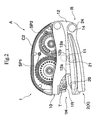
Fig. 2 is a front elevational view showing the transferring device in accordance with the embodiment; -
Fig. 3 is a front elevational view showing the other aspect of the transferring device in accordance with the embodiment; -
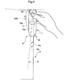
Fig. 4 is a bottom elevational view corresponding toFig. 3 ; -
Fig. 5 is a schematic cross sectional view in accordance with the embodiment; -
Fig. 6 is an explanatory view of an operation in accordance with the embodiment; -
Fig. 7 is an explanatory view of an operation in accordance with the embodiment; and -
Fig. 8 is an explanatory view of an operation in accordance with the embodiment. - A description will be given below of an embodiment in accordance with the present invention with reference to the accompanying drawings.
- A transferring device A is mainly constituted by a transferring device
main body 1 structured such as to accommodate a tape T with paste and a delivering mechanism part delivering the tape T with paste, and a receivingobject receiving cradle 2 for inserting a paper strip P with respect to the transferring devicemain body 1 at a time of transferring a paste transfer object Tb, as shown inFigs. 1 ,2 and3 . - In this case, the transferring device A in accordance with the present embodiment is provided with a
guide surface 12a capable of guiding the paper strip P in the same direction as a transferring direction at a time of sliding by being brought into contact with an edge portion Pa of the paper strip P corresponding to the receiving object, and a deflectionupper roller 11 and a deflectionlower roller 21 corresponding to a deflection roller capable of energizing the paper strip P toward theguide surface 12a at a time of sliding by being arranged so as to be deflected at a predetermined angle toward theguide surface 12a from the transferring direction. - A description will be in detail given below of a particular structure of the transferring device A with reference to
Figs. 1 ,2 ,3 ,4 and5 . - The transferring device
main body 1 is mainly constituted by acase 1C and aframe body 10, as shown inFig. 1 and the like. - The
case 1C is mainly constituted by a case main body C1 approximately forming a half-split structure and a refilling cartridge C2. - The case main body C1 is structured such that only the refilling cartridge C2 can be replaced in a state in which the case main body C1 is not generally separated from the
frame body 10 and the receivingobject receiving cradle 2, and holds a non-switched part corresponding to a part of the delivering mechanism part for supplying the tape T with paste to the paper strip P. - The refilling cartridge C2 is structured such that a
transfer head 1H corresponding to a transferring portion is attached to a front end portion thereof. Further, the structure is made such as to set the tape T with paste corresponding to an expendable part, a winding off spool SP1 and a take-up spool SP2 corresponding to a portion of the delivering mechanism part for supplying the tape T with paste to the paper strip P, and thetransfer head 1H and the like as the replaceable parts, and replace them by new ones in a state in which they are additionally provided in the refilling cartridge C2. - As shown in
Figs. 2 and3 , thetransfer head 1H is mainly constituted by the tape T with paste wound off from the winding off spool SP1 and atransfer roller 1R supporting the tape T with paste in a state of exposing the tape T with paste to an outer side of the transferring devicemain body 1. Further, thetransfer roller 1R is rotated in the same direction so as to deliver the tape T with paste, at a time of sliding the transferring device A itself in the transferring direction of transferring the paste Tb in a state in which thetransfer head 1H is brought into contact with the paper strip P. - As shown in
Figs. 2 and3 , theframe body 10 is provided with both of a function of holding thecase 1C so as to make the transferring device A in a usable state, and a function of making thecase 1C in a state in which thecase 1C can be disassembled into the case main body C1 and the refilling cartridge C2. In particular, theframe body 10 is mainly constituted by a synthetic resin integrally molded product formed in an approximately frame shape in which a part of the frame body is continuously open to upper and lower sides and thetransfer head 1H mentioned above is exposed to a lower side. Further, theframe body 10 is provided with a deflectionupper roller 11, adownward wall 12, an upperelastic pawl 13 and arotation shaft 14, and rotatably supports the receivingobject receiving cradle 2 between a pinching enablement position (X) and an exposing position (Y) corresponding to a transferring portion exposing position via a rotational moving mechanism R in a lower side. - As shown in
Figs. 2 ,3 and4 , the deflectionupper roller 11 is attached to an approximately center portion in a front view of the transferring devicemain body 1 in such a manner that a part including the lowest portion is exposed to an outer portion of theframe body 10. Particularly, in the present embodiment, as shown by using an imaginary line inFig. 4 , the deflectionupper roller 11 is attached by deflecting a mounting angle of the deflectionupper roller 11 to theframe body 10, for example, at 5 degrees with respect to a mounting direction of thetransfer roller 1R and a drawing direction of aguide surface 12a mentioned below. In this case, this mounting angle is not limited to 5 degrees shown in the present embodiment, but can be set in a range between 1 degree and 10 degrees, whereby it is possible to sufficiently achieve the effect in accordance with the present invention. Further, the transferring device A in accordance with the present embodiment is structured such as to slide the paper strip P from a side in which the rotational moving mechanism R is arranged to a side in which thetransfer head 1H is arranged, at a time of transferring. In other words, the deflectionupper roller 11 is arranged close to the transfer base end side with respect to thetransfer head 1H. In this case, in accordance with the present embodiment, the deflectionupper roller 11 is positioned at a gap space pinched between an outer periphery of the winding off spool SP1 and an outer periphery of the take-up spool SP2 in the inner portion of the transferring devicemain body 1 by being arranged in the approximately center portion in the front view, thereby achieving an effective use of the space within the inner portion of the transferring devicemain body 1 so as to achieve a compact structure of the transferring devicemain body 1. - The
downward wall 12 is formed so as to protrude downward from a slightly rear side of thetransfer head 1H over a rear end portion of theframe body 10, as shown inFigs. 3 and4 . Further, arotation shaft 14 rotatably supporting the receivingobject receiving cradle 2 is protruded from a rear end portion of thedownward wall 12. Further, an inner surface side of thedownward wall 12 forms aflat guide surface 12a provided so as to be drawn in the same direction as the transferring direction, and aconcave surface 12b provided in such a manner as to be prevented from being interfered with the deflectionupper roller 11 and the mounting position thereof, and avoiding the interference with the deflectionlower roller 21 in a state in which the transferredobject receiving cradle 2 is set to the pinching enablement position. - The upper
elastic pawl 13 is protruded to the lower side from theframe body 10 in the same manner as thedownward wall 12, as shown inFigs. 2 ,3 and4 , and is provided for maintaining the receivingobject receiving cradle 2 at the pinching enablement position (X) by being mutually engaged with a lowerelastic pawl 23 mentioned below. In more detail, it is structures such that the upperelastic pawl 13 and the lowerelastic pawl 23 are engaged with each other at a position where a distance between thetransfer roller 1R and anauxiliary roller 20 mentioned below is spaced at a small dimension with respect to the lowerelastic pawl 23, whereby at the pinching enablement position (X), the tape T with paste supported to thetransfer roller 1R and theauxiliary roller 20 can rotate only between a position where the paper strip P is pinched from two sides and the position where the tape T with paste and theauxiliary roller 20 mentioned below are spaced at the small dimension. Further, the engagement between both theelastic pawls elastic pawl 13 and the lowerelastic pawl 23 are engaged with each other to the direction in which the transferredobject receiving cradle 2 is spaced, whereby the receivingobject receiving cradle 2 comes to a state in which the exposing position (Y) shown inFigs. 3 and4 can be achieved. - The
rotation shaft 14 is structured such as to protrude from a portion near the rear end portion and the lowest portion of thedownward wall 12 and be rotatably engaged with abearing 24 mentioned below, thereby being capable of constituting a rotational moving mechanism R. Further, an elastic member (not shown) is incorporated at an engaged position between therotation shaft 14 and thebearing 24, and applies an elastic energizing force for avoiding an undesired contact between thetransfer roller 1R and theauxiliary roller 20 at the pinching enablement position (X). - As shown in
Figs. 1 ,2 ,3 and4 , the receivingobject receiving cradle 2 is rotatably attached to the transferring devicemain body 1 via the rotational moving mechanism R as mentioned above, and mainly has theauxiliary roller 20, the deflectionlower roller 21, thewall accommodating portion 22, the lowerelastic pawl 23 and thebearing 24. - The
auxiliary roller 20 is attached at a position opposite to thetransfer roller 1R in such a manner that a part including an upper end portion is exposed from the receivingobject receiving cradle 2, as shown inFig. 2 ,3 and4 , and is structured such as to smoothly execute the relative movement between the paper strip P and thetransfer head 1H by being brought into contact with the paper strip P together with thetransfer roller 1R. - The deflection
lower roller 21 is arranged at a position facing to the deflectionupper roller 11 in the present embodiment, as shown inFigs. 2 ,3 and4 . In other words, as shown by using an imaginary line inFig. 4 , it is attached by deflecting the mounting angle with respect to the receivingobject receiving cradle 2, for example, at 5 degrees with respect to the mounting direction of thetransfer roller 1R and the extending direction of theguide surface 12a mentioned below, and is attached so as to form a mirror positional relation with the deflectionupper roller 11 with respect to therotation shaft 14. Further, it is possible to effectively energize to the paper strip P mentioned below by constituting the state of being brought into contact with the paper strip P from two sides together with the deflectionupper roller 11 under the state of pinching the paper strip P. - The
wall accommodating portion 22 is a space for accommodating the lower end portion of thedownward wall 12 in the inner portion at a time of setting the receivingobject receiving cradle 2 to the pinching enablement position (X), as shown inFig. 4 . Accordingly, it is possible to achieve the smooth relative motion between the transferring devicemain body 1 and the receivingobject receiving cradle 2. - As shown in
Figs. 3 and4 , the lowerelastic pawl 23 can preferably maintain the receivingobject receiving cradle 2 at the pinching enablement position (X) by being approximately engaged with the upperelastic pawl 13, as mentioned above. - The bearing 24 preferably structures the rotational moving mechanism R by preferably rotating the receiving
object receiving cradle 2 between the pinching enablement position (X) and the exposing position as mentioned above on the basis of the engagement with therotation shaft 14, as shown inFigs. 2 and3 . - Accordingly, the transferring device A in accordance with the present embodiment is structured such as to energize the paper strip P toward the
guide surface 12a at a time of sliding the paper strip P in the transferring direction in a state of pinching the paper strip P, on the basis of the provision of the deflectionupper roller 11 and the deflectionlower roller 21 mentioned above, and theguide surface 12a, whereby the edge portion Pa of the paper strip P can be accurately brought into contact with theguide surface 12a so as to be guided. - A description will be in detail given below of a series of operations of transferring the paste Tb along the edge portion Pa of the paper strip P while making the transferring device A pinch and slide the paper strip P, with reference to
Figs. 5 ,6 ,7 and8 . - First, as shown in
Fig. 5 , in a process of transferring the paste Tb to the paper strip P, the deflectionupper roller 11 and the deflectionlower roller 21 are attached so as to be deflected at 5 degrees as mentioned above. In other words, when the deflectionupper roller 11 and the deflectionlower roller 21 are rotated while being brought into contact with the paper strip P, the paper strip P is delivered at an angle deflected to theguide surface 12a at 5 degrees with respect to the transferring direction. - Further, as shown in
Figs. 6 ,7 and8 , at a time of a series of operations when the user grips the transferring device A by the hand, and slides the transferring device A in the transferring direction mainly on the basis of the bending motion of the wrist, the deflectionupper roller 11 and the deflectionlower roller 21 deliver the paper strip P in the direction deflected at 5 degrees from the transferring direction, whereby the end portion Pa of the paper strip P is moved in the direction of being brought into contact with theguide surface 12a or the state of being brought into contact with theguide surface 12a is maintained. In this case, the direction in which the paper strip P is energized is schematically shown by an arrow in the drawing. Further, as shown inFigs. 7 and8 , even in the case that a force in an undesired direction is applied in the direction in which the end portion Pa and theguide surface 12a are moved away from each other, on the basis of the snap motion using the bending of the wrist or the like, the energizing force by the deflectionupper roller 11 and the deflectionlower roller 21 cancels the force in the undesired direction, whereby the paper strip P is slid accurately while being corrected in the direction in which theguide surface 12a is extended, that is, the transferring direction. Particularly as shown inFig. 6 , even in the case that the end portion Pa of the paper strip P is arranged so as to be deflected at a slight angle from the transferring direction in a state in which the paste has not transferred yet, such as the paper strip P shown by an imaginary line in the drawing, at a time of starting the transfer (or immediately before the transfer), the deflectionupper roller 11 and the deflectionlower roller 21 are positioned in the transfer base end side rather than thetransfer roller 1R. Accordingly, the direction of the end portion Pa of the paper strip P is corrected by the deflectionupper roller 11 and the deflectionlower roller 21, and the paste Tb is correctly transferred in the transferring direction from the transfer starting time. Of course, even in the case that the position of the paper strip P is erroneously shifted in the process of the transfer as shown inFig. 7 , the direction of the end portion Pa of the paper strip P is corrected by the deflectionupper roller 11 and the deflectionlower roller 21 while transferring the paste Tb. - Further, since the transferring device A structures the rotational moving mechanism R rotatably connecting the transferring device
main body 1 and the receivingobject receiving cradle 2, by therotation shaft 14 and thebearing 24, for example, in the case that it is intended to transfer the paste Tb to a desired position of the paper strip P mounted on the desk or the like or in the case that the transferring device is used in the same manner as the existing transferring device, it is preferable to rotationally move the receivingobject receiving cradle 2 to the lower side so as to achieve the exposing position (Y) shown inFig. 3 in which thetransfer head 1H is exposed. - As mentioned above, since the transferring device A in accordance with the present embodiment is provided with the
guide surface 12a which can guide in the same direction as the transferring direction, and the deflectionupper roller 11 and the deflectionlower roller 21 corresponding to the deflection roller arranged at 5 degrees corresponding to the predetermined angle toward theguide surface 12a from the transferring direction, it is possible to effectively cancel the displacement of the paste Tb corresponding to the transfer object caused by the deflection between the transferring device A and the paper strip P in accordance with the snap or the like (Figs. 6 ,7 and8 ) using the bending of the wrist at a time of sliding the paper strip P, and it is possible to accurately guide the paper strip P to theguide surface 12a provided in the same direction as the transferring direction. In accordance with the structure mentioned above, the user can slide the transferring device A on the basis of a natural operation without being sensitive about the snap using the bending of the wrist, a rotation of an elbow or the like, thereby accurately transferring the paste Tb corresponding to the transfer object along the edge portion Pa of the paper strip P. Further, even in the case that the user slides the transferring device A while being conscious of the transferring direction, theguide surface 12a and the rotating direction of thetransfer roller 1R, that is, the transferring direction are set to the same direction. Accordingly, it is possible to effectively avoid the matter that the paste Tb is transferred so as to be deflected in accordance that the paste Tb eats into the inner side from the edge portion Pa of the paper strip P. - Further, since the deflection
upper roller 11 and the deflectionlower roller 21 are provided at the respective facing positions in the transferring devicemain body 1 side and the receivingobject receiving cradle 2 side, the structure is made such that the paper strip P is delivered while pinching the same position in the paper strip P from two sides, whereby the paper strip P can be smoothly energized to theguide surface 12a side. Further, since the deflectionupper roller 11 and the deflectionlower roller 21 are arranged in the transfer base end side which can be brought into contact with the paper strip P prior to thetransfer head 1H corresponding to the transferring portion, the paper strip P can be brought into contact with thetransfer head 1H in the state in which the paper strip P is previously energized in the deflected direction so as to be positioned to theguide surface 12a, thereby being in the accurate position and direction from the starting stage of the transfer. Further, since the angle at which the deflectionupper roller 11 and the deflectionlower roller 21 corresponding to the deflection roller are deflected is set to 5 degrees in the present embodiment, that is, within the range between 1 degree and 10 degrees mentioned above, it is possible to effectively avoid the matter that the sufficient energizing force can not be obtained due to the too small angle while effectively avoiding an appearance of wrinkle or the like caused by the unnatural energization of the paper strip P due to the too large angle. In other words, it is possible to preferably transfer the paste Tb by converting the operating force on the basis of the sliding motion into the proper energizing force. - The description is given above of the embodiment in accordance with the present invention, however, the particular structures of the respective portions are not limited to only the embodiment mentioned above, but can be variously modified within the terms of the appended claims.
- For example, the deflection upper roller is provided in the frame body in the embodiment mentioned above, however, it may be constituted by a replacement part additionally provided in the cartridge. Further, the angle at which the deflection roller is deflected is not limited to the angle mentioned above, but can be set to various angles in accordance with the magnitude, the shape or the like of the roller. Further, the deflection rollers are not respectively limited to the single rollers, but may be constituted by a structure in which a plurality of rollers are provided so as to face to each other, or a structure in which a caterpillar-shaped crawler belt is provided in outer peripheries of a plurality of rollers so as to form an endless track.
Claims (5)
- A transferring device, comprising- a transferring device main body (1) having a transferring portion (1H) for transferring a transfer object (Tb) to a receiving object (P) such as paper,- a receiving object receiving cradle (2) provided on the transferring device main body (1),- wherein the transferring device is structured such that the transfer object (Tb) is transferred to the receiving object (P) by the transferring device and the receiving object (P) being slid relative to each other in a predetermined transferring direction in a state in which the receiving object (P) is pinched between the
transferring device main body (1) and the receiving object receiving cradle (2),- a guide surface (12a) capable of guiding the receiving object (P) in the same direction as the transferring direction at a time of the sliding movement by being brought into contact with an edge portion of the receiving object (P), andcharacterized
a roller for contacting and pinching the receiving object (P) at the time of the sliding movement,
in that the roller is a deflection roller (11, 21) capable of energizing the receiving object (P) toward the guide surface (12a) at the time of the sliding movement by being arranged so as to be deflected at a predetermined angle toward the guide surface (12a) from the transferring direction. - The transferring device as claimed in claim 1, comprising a second deflection roller (11, 21) capable of energizing the receiving object (P) toward the guide surface (12a) at the time of the sliding movement by being arranged so as to be deflected at a predetermined angle toward the guide surface (12a) from the transferring direction, wherein the deflection rollers (11, 21) are provided at respective facing positions on the transferring device main body (1) side and the receiving object receiving cradle (2) side.
- The transferring device as claimed in claim 1 or 2, wherein the deflection roller (11, 21) or the deflection rollers is/are arranged in a transfer base end side in the transferring direction remote from the transferring portion (1H).
- The transferring device as claimed in one of claims 1 to 3, wherein the predetermined angle by which the deflection roller (11, 21) or the deflection rollers is/are deflected, is set to 1 degree to 10 degrees.
- The transferring device as claimed in one of claims 1 to 4, furthermore comprising a rotational moving mechanism (R) for relatively moving the receiving object receiving cradle (2) with respect to the transferring device main body (1) between a pinching enablement position (X) capable of pinching the receiving object (P) and a transferring portion exposing position (Y) at which a leading end portion of the transferring portion (1H) is exposed.
Applications Claiming Priority (1)
| Application Number | Priority Date | Filing Date | Title |
|---|---|---|---|
| JP2005330875A JP4774531B2 (en) | 2005-11-15 | 2005-11-15 | Transfer tool |
Publications (2)
| Publication Number | Publication Date |
|---|---|
| EP1785380A1 EP1785380A1 (en) | 2007-05-16 |
| EP1785380B1 true EP1785380B1 (en) | 2009-07-29 |
Family
ID=37872169
Family Applications (1)
| Application Number | Title | Priority Date | Filing Date |
|---|---|---|---|
| EP06122843A Not-in-force EP1785380B1 (en) | 2005-11-15 | 2006-10-24 | Transferring device |
Country Status (6)
| Country | Link |
|---|---|
| US (2) | US7802603B2 (en) |
| EP (1) | EP1785380B1 (en) |
| JP (1) | JP4774531B2 (en) |
| CN (1) | CN100564069C (en) |
| CA (1) | CA2565560C (en) |
| DE (1) | DE602006008088D1 (en) |
Families Citing this family (3)
| Publication number | Priority date | Publication date | Assignee | Title |
|---|---|---|---|---|
| JP6164497B2 (en) * | 2012-05-29 | 2017-07-19 | フジコピアン株式会社 | Film transfer tool |
| CN105398195B (en) * | 2015-12-02 | 2018-01-26 | 邹栋 | Transfer the transfer device of wave pattern |
| CN105437744B (en) * | 2015-12-02 | 2017-11-14 | 邹栋 | Thing is transferred from the molding transfer tool separated |
Family Cites Families (13)
| Publication number | Priority date | Publication date | Assignee | Title |
|---|---|---|---|---|
| JPS6456869A (en) * | 1987-08-28 | 1989-03-03 | Nippon Telegraph & Telephone | Thin film forming device |
| JPH02301500A (en) * | 1989-05-16 | 1990-12-13 | Kyuji Yoshida | Apparatus for automatically bonding adhesive tape |
| JPH0480174A (en) * | 1990-07-21 | 1992-03-13 | Hitoshi Suzuki | Sticking device for adhesive tape |
| DE4104331A1 (en) * | 1991-02-13 | 1992-08-27 | Henkel Kgaa | Dispenser for adhesive tape - separates backing strip from tape and has second roller to receive backing strip |
| US5405471A (en) * | 1992-05-19 | 1995-04-11 | Lemaster; Timothy S. | Splicing apparatus and process |
| JP2626594B2 (en) * | 1994-12-08 | 1997-07-02 | コクヨ株式会社 | Tape glue application device |
| JP2001123127A (en) * | 1999-10-26 | 2001-05-08 | Kansai Paint Co Ltd | Adhesive tape sticking jig |
| JP2002178694A (en) | 2000-12-14 | 2002-06-26 | Tombow Pencil Co Ltd | Paint transfer tool |
| JP2003326778A (en) * | 2002-05-14 | 2003-11-19 | Noritsu Koki Co Ltd | Thermal fixing device and image forming device |
| JP4133089B2 (en) * | 2002-08-01 | 2008-08-13 | 株式会社トンボ鉛筆 | Electric film transfer device |
| JP4133130B2 (en) * | 2002-08-30 | 2008-08-13 | 株式会社トンボ鉛筆 | Electric film transfer device |
| JP4367221B2 (en) * | 2004-05-06 | 2009-11-18 | コクヨ株式会社 | Transfer tool |
| JP4352984B2 (en) * | 2004-05-06 | 2009-10-28 | コクヨ株式会社 | Transfer tool |
-
2005
- 2005-11-15 JP JP2005330875A patent/JP4774531B2/en not_active Expired - Lifetime
-
2006
- 2006-10-24 DE DE602006008088T patent/DE602006008088D1/en active Active
- 2006-10-24 EP EP06122843A patent/EP1785380B1/en not_active Not-in-force
- 2006-10-25 CA CA002565560A patent/CA2565560C/en not_active Expired - Fee Related
- 2006-11-13 US US11/595,855 patent/US7802603B2/en active Active
- 2006-11-15 CN CNB2006101465919A patent/CN100564069C/en not_active Expired - Fee Related
-
2010
- 2010-06-30 US US12/827,779 patent/US8171976B2/en not_active Expired - Fee Related
Also Published As
| Publication number | Publication date |
|---|---|
| JP2007136753A (en) | 2007-06-07 |
| CN100564069C (en) | 2009-12-02 |
| DE602006008088D1 (en) | 2009-09-10 |
| US20100263799A1 (en) | 2010-10-21 |
| US7802603B2 (en) | 2010-09-28 |
| EP1785380A1 (en) | 2007-05-16 |
| CA2565560A1 (en) | 2007-05-15 |
| CA2565560C (en) | 2009-10-13 |
| CN1966284A (en) | 2007-05-23 |
| JP4774531B2 (en) | 2011-09-14 |
| HK1100388A1 (en) | 2007-09-21 |
| US20070107850A1 (en) | 2007-05-17 |
| US8171976B2 (en) | 2012-05-08 |
Similar Documents
| Publication | Publication Date | Title |
|---|---|---|
| RU2143394C1 (en) | Ribbon meter | |
| US7900679B2 (en) | Transfer tool | |
| US8360128B2 (en) | Transfer tool | |
| EP1982844A1 (en) | Coating transfer tool | |
| KR100313654B1 (en) | Applicator | |
| RU97110076A (en) | TAPE DISPENSER | |
| KR950008168A (en) | Coating Warrior | |
| JPH0771656B2 (en) | Sheet material supply device | |
| EP2335946A1 (en) | Transfer tool | |
| KR20060080206A (en) | Rotary Applicator Tip of Correction Tape Dispenser | |
| JP2005193410A (en) | Transfer implement | |
| US8171976B2 (en) | Transferring device | |
| JP4352984B2 (en) | Transfer tool | |
| US7703715B2 (en) | Transfer tool | |
| JP4491550B2 (en) | Engaging device and transfer tool | |
| HU220914B1 (en) | Hand-operated instrument for transferring a film from a support sheet to a substrate | |
| JP2020172052A (en) | Coating film transfer tool | |
| JP4005131B2 (en) | Tape dispenser | |
| JP5786115B2 (en) | Transfer tool | |
| JPH0697699A (en) | Electronic part supply device | |
| JP4367221B2 (en) | Transfer tool | |
| JP7122985B2 (en) | transfer tool | |
| JP2023008076A (en) | dispenser | |
| JP2009119835A (en) | Coating film transfer tool equipped with dumping head | |
| JP2002520194A (en) | Equipment for transferring film-like substances applied to carrier tape |
Legal Events
| Date | Code | Title | Description |
|---|---|---|---|
| PUAI | Public reference made under article 153(3) epc to a published international application that has entered the european phase |
Free format text: ORIGINAL CODE: 0009012 |
|
| 17P | Request for examination filed |
Effective date: 20061024 |
|
| AK | Designated contracting states |
Kind code of ref document: A1 Designated state(s): AT BE BG CH CY CZ DE DK EE ES FI FR GB GR HU IE IS IT LI LT LU LV MC NL PL PT RO SE SI SK TR |
|
| AX | Request for extension of the european patent |
Extension state: AL BA HR MK YU |
|
| 17Q | First examination report despatched |
Effective date: 20070726 |
|
| AKX | Designation fees paid |
Designated state(s): DE FR GB IT |
|
| GRAP | Despatch of communication of intention to grant a patent |
Free format text: ORIGINAL CODE: EPIDOSNIGR1 |
|
| GRAS | Grant fee paid |
Free format text: ORIGINAL CODE: EPIDOSNIGR3 |
|
| GRAA | (expected) grant |
Free format text: ORIGINAL CODE: 0009210 |
|
| AK | Designated contracting states |
Kind code of ref document: B1 Designated state(s): DE FR GB IT |
|
| REG | Reference to a national code |
Ref country code: GB Ref legal event code: FG4D |
|
| REF | Corresponds to: |
Ref document number: 602006008088 Country of ref document: DE Date of ref document: 20090910 Kind code of ref document: P |
|
| PLBE | No opposition filed within time limit |
Free format text: ORIGINAL CODE: 0009261 |
|
| STAA | Information on the status of an ep patent application or granted ep patent |
Free format text: STATUS: NO OPPOSITION FILED WITHIN TIME LIMIT |
|
| 26N | No opposition filed |
Effective date: 20100503 |
|
| PGFP | Annual fee paid to national office [announced via postgrant information from national office to epo] |
Ref country code: DE Payment date: 20141023 Year of fee payment: 9 Ref country code: GB Payment date: 20141022 Year of fee payment: 9 Ref country code: FR Payment date: 20141008 Year of fee payment: 9 |
|
| PGFP | Annual fee paid to national office [announced via postgrant information from national office to epo] |
Ref country code: IT Payment date: 20141015 Year of fee payment: 9 |
|
| REG | Reference to a national code |
Ref country code: DE Ref legal event code: R119 Ref document number: 602006008088 Country of ref document: DE |
|
| GBPC | Gb: european patent ceased through non-payment of renewal fee |
Effective date: 20151024 |
|
| PG25 | Lapsed in a contracting state [announced via postgrant information from national office to epo] |
Ref country code: IT Free format text: LAPSE BECAUSE OF NON-PAYMENT OF DUE FEES Effective date: 20151024 Ref country code: GB Free format text: LAPSE BECAUSE OF NON-PAYMENT OF DUE FEES Effective date: 20151024 Ref country code: DE Free format text: LAPSE BECAUSE OF NON-PAYMENT OF DUE FEES Effective date: 20160503 |
|
| REG | Reference to a national code |
Ref country code: FR Ref legal event code: ST Effective date: 20160630 |
|
| PG25 | Lapsed in a contracting state [announced via postgrant information from national office to epo] |
Ref country code: FR Free format text: LAPSE BECAUSE OF NON-PAYMENT OF DUE FEES Effective date: 20151102 |