EP1743779A1 - Transfer tool - Google Patents
Transfer tool Download PDFInfo
- Publication number
- EP1743779A1 EP1743779A1 EP05737131A EP05737131A EP1743779A1 EP 1743779 A1 EP1743779 A1 EP 1743779A1 EP 05737131 A EP05737131 A EP 05737131A EP 05737131 A EP05737131 A EP 05737131A EP 1743779 A1 EP1743779 A1 EP 1743779A1
- Authority
- EP
- European Patent Office
- Prior art keywords
- transfer
- transferred object
- transfer tool
- main body
- face
- Prior art date
- Legal status (The legal status is an assumption and is not a legal conclusion. Google has not performed a legal analysis and makes no representation as to the accuracy of the status listed.)
- Granted
Links
- 238000012546 transfer Methods 0.000 title claims abstract description 660
- 238000003780 insertion Methods 0.000 claims abstract description 61
- 230000037431 insertion Effects 0.000 claims abstract description 61
- 239000000463 material Substances 0.000 claims description 44
- 238000004804 winding Methods 0.000 claims description 24
- 230000007246 mechanism Effects 0.000 claims description 22
- 230000001105 regulatory effect Effects 0.000 claims description 18
- 238000000034 method Methods 0.000 claims description 5
- 230000008569 process Effects 0.000 claims description 3
- 238000003466 welding Methods 0.000 claims description 3
- 239000003292 glue Substances 0.000 abstract description 27
- 238000005096 rolling process Methods 0.000 description 20
- 230000007547 defect Effects 0.000 description 4
- 229920003002 synthetic resin Polymers 0.000 description 3
- 239000000057 synthetic resin Substances 0.000 description 3
- 210000000707 wrist Anatomy 0.000 description 3
- 239000000853 adhesive Substances 0.000 description 2
- 230000001070 adhesive effect Effects 0.000 description 2
- 239000002390 adhesive tape Substances 0.000 description 2
- 230000008901 benefit Effects 0.000 description 2
- 230000008859 change Effects 0.000 description 2
- 230000002452 interceptive effect Effects 0.000 description 2
- 239000007788 liquid Substances 0.000 description 2
- 230000004044 response Effects 0.000 description 2
- 239000007787 solid Substances 0.000 description 2
- 241000251468 Actinopterygii Species 0.000 description 1
- 238000012937 correction Methods 0.000 description 1
- 230000000694 effects Effects 0.000 description 1
- 210000003811 finger Anatomy 0.000 description 1
- 238000012986 modification Methods 0.000 description 1
- 230000004048 modification Effects 0.000 description 1
- 210000003813 thumb Anatomy 0.000 description 1
Images


Classifications
-
- B—PERFORMING OPERATIONS; TRANSPORTING
- B43—WRITING OR DRAWING IMPLEMENTS; BUREAU ACCESSORIES
- B43M—BUREAU ACCESSORIES NOT OTHERWISE PROVIDED FOR
- B43M11/00—Hand or desk devices of the office or personal type for applying liquid, other than ink, by contact to surfaces, e.g. for applying adhesive
- B43M11/06—Hand-held devices
-
- B—PERFORMING OPERATIONS; TRANSPORTING
- B43—WRITING OR DRAWING IMPLEMENTS; BUREAU ACCESSORIES
- B43L—ARTICLES FOR WRITING OR DRAWING UPON; WRITING OR DRAWING AIDS; ACCESSORIES FOR WRITING OR DRAWING
- B43L19/00—Erasers, rubbers, or erasing devices; Holders therefor
-
- B—PERFORMING OPERATIONS; TRANSPORTING
- B43—WRITING OR DRAWING IMPLEMENTS; BUREAU ACCESSORIES
- B43L—ARTICLES FOR WRITING OR DRAWING UPON; WRITING OR DRAWING AIDS; ACCESSORIES FOR WRITING OR DRAWING
- B43L19/00—Erasers, rubbers, or erasing devices; Holders therefor
- B43L19/0056—Holders for erasers
- B43L19/0068—Hand-held holders
-
- B—PERFORMING OPERATIONS; TRANSPORTING
- B65—CONVEYING; PACKING; STORING; HANDLING THIN OR FILAMENTARY MATERIAL
- B65H—HANDLING THIN OR FILAMENTARY MATERIAL, e.g. SHEETS, WEBS, CABLES
- B65H37/00—Article or web delivery apparatus incorporating devices for performing specified auxiliary operations
- B65H37/002—Web delivery apparatus, the web serving as support for articles, material or another web
- B65H37/005—Hand-held apparatus
- B65H37/007—Applicators for applying coatings, e.g. correction, colour or adhesive coatings
-
- Y—GENERAL TAGGING OF NEW TECHNOLOGICAL DEVELOPMENTS; GENERAL TAGGING OF CROSS-SECTIONAL TECHNOLOGIES SPANNING OVER SEVERAL SECTIONS OF THE IPC; TECHNICAL SUBJECTS COVERED BY FORMER USPC CROSS-REFERENCE ART COLLECTIONS [XRACs] AND DIGESTS
- Y10—TECHNICAL SUBJECTS COVERED BY FORMER USPC
- Y10T—TECHNICAL SUBJECTS COVERED BY FORMER US CLASSIFICATION
- Y10T156/00—Adhesive bonding and miscellaneous chemical manufacture
- Y10T156/17—Surface bonding means and/or assemblymeans with work feeding or handling means
- Y10T156/1702—For plural parts or plural areas of single part
- Y10T156/1705—Lamina transferred to base from adhered flexible web or sheet type carrier
-
- Y—GENERAL TAGGING OF NEW TECHNOLOGICAL DEVELOPMENTS; GENERAL TAGGING OF CROSS-SECTIONAL TECHNOLOGIES SPANNING OVER SEVERAL SECTIONS OF THE IPC; TECHNICAL SUBJECTS COVERED BY FORMER USPC CROSS-REFERENCE ART COLLECTIONS [XRACs] AND DIGESTS
- Y10—TECHNICAL SUBJECTS COVERED BY FORMER USPC
- Y10T—TECHNICAL SUBJECTS COVERED BY FORMER US CLASSIFICATION
- Y10T156/00—Adhesive bonding and miscellaneous chemical manufacture
- Y10T156/17—Surface bonding means and/or assemblymeans with work feeding or handling means
- Y10T156/1788—Work traversing type and/or means applying work to wall or static structure
-
- Y—GENERAL TAGGING OF NEW TECHNOLOGICAL DEVELOPMENTS; GENERAL TAGGING OF CROSS-SECTIONAL TECHNOLOGIES SPANNING OVER SEVERAL SECTIONS OF THE IPC; TECHNICAL SUBJECTS COVERED BY FORMER USPC CROSS-REFERENCE ART COLLECTIONS [XRACs] AND DIGESTS
- Y10—TECHNICAL SUBJECTS COVERED BY FORMER USPC
- Y10T—TECHNICAL SUBJECTS COVERED BY FORMER US CLASSIFICATION
- Y10T156/00—Adhesive bonding and miscellaneous chemical manufacture
- Y10T156/17—Surface bonding means and/or assemblymeans with work feeding or handling means
- Y10T156/1788—Work traversing type and/or means applying work to wall or static structure
- Y10T156/1795—Implement carried web supply
-
- Y—GENERAL TAGGING OF NEW TECHNOLOGICAL DEVELOPMENTS; GENERAL TAGGING OF CROSS-SECTIONAL TECHNOLOGIES SPANNING OVER SEVERAL SECTIONS OF THE IPC; TECHNICAL SUBJECTS COVERED BY FORMER USPC CROSS-REFERENCE ART COLLECTIONS [XRACs] AND DIGESTS
- Y10—TECHNICAL SUBJECTS COVERED BY FORMER USPC
- Y10T—TECHNICAL SUBJECTS COVERED BY FORMER US CLASSIFICATION
- Y10T156/00—Adhesive bonding and miscellaneous chemical manufacture
- Y10T156/17—Surface bonding means and/or assemblymeans with work feeding or handling means
- Y10T156/1798—Surface bonding means and/or assemblymeans with work feeding or handling means with liquid adhesive or adhesive activator applying means
-
- Y—GENERAL TAGGING OF NEW TECHNOLOGICAL DEVELOPMENTS; GENERAL TAGGING OF CROSS-SECTIONAL TECHNOLOGIES SPANNING OVER SEVERAL SECTIONS OF THE IPC; TECHNICAL SUBJECTS COVERED BY FORMER USPC CROSS-REFERENCE ART COLLECTIONS [XRACs] AND DIGESTS
- Y10—TECHNICAL SUBJECTS COVERED BY FORMER USPC
- Y10T—TECHNICAL SUBJECTS COVERED BY FORMER US CLASSIFICATION
- Y10T156/00—Adhesive bonding and miscellaneous chemical manufacture
- Y10T156/18—Surface bonding means and/or assembly means with handle or handgrip
-
- Y—GENERAL TAGGING OF NEW TECHNOLOGICAL DEVELOPMENTS; GENERAL TAGGING OF CROSS-SECTIONAL TECHNOLOGIES SPANNING OVER SEVERAL SECTIONS OF THE IPC; TECHNICAL SUBJECTS COVERED BY FORMER USPC CROSS-REFERENCE ART COLLECTIONS [XRACs] AND DIGESTS
- Y10—TECHNICAL SUBJECTS COVERED BY FORMER USPC
- Y10T—TECHNICAL SUBJECTS COVERED BY FORMER US CLASSIFICATION
- Y10T156/00—Adhesive bonding and miscellaneous chemical manufacture
- Y10T156/19—Delaminating means
-
- Y—GENERAL TAGGING OF NEW TECHNOLOGICAL DEVELOPMENTS; GENERAL TAGGING OF CROSS-SECTIONAL TECHNOLOGIES SPANNING OVER SEVERAL SECTIONS OF THE IPC; TECHNICAL SUBJECTS COVERED BY FORMER USPC CROSS-REFERENCE ART COLLECTIONS [XRACs] AND DIGESTS
- Y10—TECHNICAL SUBJECTS COVERED BY FORMER USPC
- Y10T—TECHNICAL SUBJECTS COVERED BY FORMER US CLASSIFICATION
- Y10T225/00—Severing by tearing or breaking
- Y10T225/20—Severing by manually forcing against fixed edge
- Y10T225/238—With housing for work supply
- Y10T225/252—With brake or tensioner
Definitions
- the present invention relates to a transfer tool used for transferring a transfer material on a transferred object such as paper.
- the transfer tool for transferring such a transfer material is provided with a case holding the transfer material therein and a transfer head for transferring the transfer material held in the case to the transferred object.
- This transfer head serves to transfer the transfer material on the transferred object contacting the transferred object.
- Such a transfer tool is configured so as to transfer the transfer material on the surface of the transferred object when a user has a holder in his or her hand to slidably move a transfer head on the transferred object with the transfer head contacting the surface of the transferred object (for example, refer to a patent document 1)
- the transfer in order to carry out the stable transfer operation, the transfer is performed with the transferred object such as paper mounted on a flat face plate such as a desk and a work table, and this generates a defect that a place where the transfer tool can be used is limited.
- an underlay may be further mounted on the flat face plate such as the desk or the work table and the transferred object may be mounted thereon. In this case, the work before the transfer material is transferred on the transferred object is troublesome, so that this involves a problem such that the transfer operation cannot be carried out immediately and a practical utility is lacked.
- the present invention has been made taking the foregoing problems into consideration and an object of which is to provide a transfer tool that can be preferably used without a table such as a desk and can easily carry out the transfer operation in any places.
- the present invention may comprise a transfer tool used for transferring a transfer material on a transferred object such as paper, including: a transfer tool main body having a transfer head that can bring at least the transfer material into contact with the transferred object; and a transferred object receiver that is accompanied by the transfer tool main body; wherein the transfer head has a transfer face that is a region contacting the transferred object and transferring the transfer material when transferring the transfer material on the transferred object; an insertion space is formed between the transfer tool main body and the transferred object receiver, in which the transferred object can be inserted; the transfer head is positioned so that at least the transfer face is exposed in the insertion space; and the transfer material is transferred on the transferred object by slidably moving the transfer face to a predetermined transfer direction while bringing the transfer face into contact with the transferred object with the transferred object inserted in the insertion space and the transferred object sandwiched between the transfer tool main body and the transferred object receiver.
- a transfer direction means a direction for moving the transfer tool to the transferred object in the case of using the transfer tool with the transferred object sandwiched between the transfer tool main body and the transferred object.
- a usage mode that is not applied to the conventional transfer tool, namely, a usage mode that the transfer is carried out with paper sandwiched between the transfer tool main body and the transferred object receiver can be employed. Therefore, it is not necessary to use a board such as a table and a desk on which the transferred object is mounted upon transfer and the transfer tool according to the present invention can easily transfer the transfer material on the transferred object in any times and any places. As a result, it is natural that the work to further mount the underlay on the surface of the table or the like is not needed, so that it is preferable that the transfer operation can be carried out immediately.
- the present transfer tool can preferably transfer the transfer material on the transferred object having any specifications and any shapes.
- the present transfer tool since the present transfer tool has such an insertion space, the present transfer tool also can transfer the transfer material on the transferred object by inserting paper into the insertion space that is formed between the transfer tool main body and the transferred object receiver with the transfer tool main body brought close to the transferred object receiver in advance, and sliding and moving the paper to the transfer direction. In this case, the transfer tool can perform the transfer operation more simply since the operation to grasp the transfer tool is not necessary.
- the configuration of the transfer tool can be effectively simplified and the number of parts thereof can be effectively reduced.
- the transfer head includes a transfer roller having the transfer face that can be rotated upon transfer, it is possible to contact the transferred object and the transfer face more smoothly to improve the transfer property.
- a first auxiliary roller is provided on the transferred object receiver, which can be rotated in conjunction with the transfer roller upon transfer, it is possible to smoothly carry out the transfer operation with the transferred object sandwiched between the transfer tool main body and the transferred object receiver.
- the first auxiliary roller may be provided at a position opposed to the transfer roller.
- the first auxiliary roller has a backing face that is a region that can be opposed to the transfer face and can contact the rear face of the transferred object upon transfer and the backing face and the transfer face are relatively connected and separated each other, the backing face and the transfer face are relatively contacted and separated in response to the thickness of the transferred object to be transferred upon transfer, it is possible to bring the backing face and the transfer face into contact with the front surface and the rear surface of the transferred object, respectively, and bite into the transferred object is improved.
- the embodiment that the transferred object receiver includes a base and at least the first auxiliary roller, and further includes an arm portion that can carry out the balancing operation with respect to the base and the embodiment that the first auxiliary roller cradle supporting a rotational support shaft of the first auxiliary roller is configured so as to be elastically deformed in a direction connecting and separating to and from the transfer head are conceivable.
- the first auxiliary roller is formed by a cushion material that is elastically deformed at least in a direction connecting and separating to and from the transfer head, these advantages can be more effective.
- the transferred object is closely related to the transfer tool in at least two places within the insertion space. As a result, it is possible to smoothly move the transferred object and a straight through property to the transferred object of the transfer tool can be effectively improved.
- a first endless track mechanism winding a crawler track between at least one of the second auxiliary roller and the transfer roller may be provided with the transfer tool main body.
- a second endless track mechanism winding a crawler track between at least one of the second auxiliary roller and the first auxiliary roller is provided at the transferred object receiver, the transfer operation can be carried out smoothly with a stable state.
- the embodiment that can adjust the second auxiliary rollers opposed with each other flexibly in response to the thickness of the like of the transferred object includes a base and at least one of the second auxiliary roller and further includes an arm portion that can carry out the balancing operation with respect to the base or the embodiment that the transferred object receiver includes at least one of the second auxiliary roller and a second auxiliary roller cradle supporting a rotational support shaft of the second auxiliary roller is configured so as to be elastically deformed in a direction connecting and separating to and from the other second auxiliary roller that is provided with the transfer tool main body so as to be opposed to the one second auxiliary roller are conceivable.
- the present transfer tool can be used in the same way as the known transfer tool, namely, without sandwiching the transferred object between the transfer tool main body and the transferred object receiver. Therefore, by appropriately changing the usage mode depending on the application, the present transfer tool becomes more practical.
- the embodiment provided with a slidably moving mechanism which relatively moves the transferred object receiver between the transfer head covered position and the transfer head exposed position by slidably moving the transferred object receiver in the transfer direction or in the reverse transfer direction with respect to the transfer tool main body is available.
- the embodiment that the slidably moving mechanism is configured by a shaft provided at the transfer tool main body and a bearing portion formed on the transferred object receiver so as to support the shaft; a groove is formed on the bearing portion, in which the shaft can be inserted and which is elongated in the transfer direction or in the reverse transfer direction; and the transferred object receiver is configured so as to be slidabely movable with respect to the transfer tool main body between the transfer head covered position and the transfer head exposed position by slidably moving the shaft along the elongated direction of the groove is available.
- the embodiment including a rotatably moving mechanism which relatively moves the transferred object receiver between the transfer head covered position and the transfer head exposed position by rotatably moving the transferred object receiver in a predetermined direction with respect to the transfer tool main body is conceivable.
- the rotatably moving mechanism is configured by a shaft provided at the transfer tool main body and a bearing portion formed on the transferred object receiver so as to rotatably support the shaft; and the transferred object receiver is configured so as to be rotatably movable with respect to the transfer tool main body between the transfer head covered position and the transfer head exposed position using a pivoting point between the shaft and the bearing portion as a support point, by rotatabily clearing the transferred object receiver located at the transfer head covered position, the transferred object receiver is located at the transfer head exposed position with the simple operation.
- regulating means which prevents the transfer tool main body and the transferred object receiver from moving close each other for a predetermined distance or more upon transfer, it is possible to prevent so-called bite and deformation and damage of a member that may occur when the transfer tool main body comes close to the transferred object receiver beyond necessity.
- the embodiment that the regulating means uses an elongated chip that is provided at any one of the transfer tool main body or the transferred object receiver and is elongated to the other one; and the elongated chip abuts against the other one by priority when transferring the transfer material on the transferred object is conceivable. According to such a transfer tool, by using the simple structure, it is possible to surely prevent the transfer tool main body and the transferred object receiver from coming close to each other beyond necessity.
- guide means which can abut against the edge portion of the transferred object when the transferred object is inserted in the insertion space and the transferred object is guided by this guide means so as to be movable in the insertion space, by abutting the edge of the transferred object against the guide means, the dimension of the insertion depth of the transferred object with respect to the transfer tool is made constant, so that it is possible to perform transfer approximately in parallel with the edge of the transferred object.
- the embodiment the guide means uses an elongated chip that is provided at any one of the transfer tool main body or the transferred object receiver and is elongated to the other one is available.
- regulating means may be provided, which prevents the transfer tool main body and the transferred object receiver from moving close each other for a predetermined distance or more upon transfer; the regulating means may function as the guide means that can abut against the edge portion of the transferred object when the transferred object is inserted in the insertion space.
- the regulating means may use an elongated chip that is provided at any one of the transfer tool main body or the transferred object receiver and is elongated to the other one; the elongated chip may abut against the other one by priority when transferring the transfer material on the transferred object. If the guide means uses the elongated chip, the regulating means and the guide means can be realized by using one member. Therefore, as compared to the embodiment that the regulating means and the guide means are configured by using separate members respectively, the number of the parts can be effectively reduced.
- the elongated chip can close one side along the transfer direction, it is possible to keep the dimension for sandwiching the transferred object and the dimension of the insertion depth of the transferred object into the insertion space constant.
- a shaft to rotatably support the transferred object receiver with respect to the transfer tool main body is firmly fixed to the transfer tool main body; a pair of opposed edge portions is formed on the shaft, which are located approximately in parallel with each other at least seen from the side and are elongated along the elongated direction of the transferred object receiver; the initial state is set so that these opposed edge portions are different from the transfer direction; an elastically deforming part is provided, in which a bearing portion for inserting the shaft is formed at the transferred object receiver and an opening portion having the approximately same opening dimension as the distance between the opposed edge portions of the shaft is formed; the shaft is inserted in a region where the opening portion and the bearing portion are communicated in the initial state; when the elastically deforming parties are configured to accumulate a urging force to urge the transferred object receiver to a direction to separate the transferred object receiver from the transfer tool main body, by elastically deforming the elastically deforming part due to the pressure welding force between the opposed edge portion and the inside portion of the opening portion, during the process of rotating the transferred
- an inward face located at least the side of the insertion space of the elongated chip and a first virtual standing face that is a virtual standing face passing through the transfer face may form a blunt angle opening to the transfer direction.
- the embodiment that making the first virtual standing face to be orthogonal to the transfer direction, the inward face and the first virtual standing face are set to form the blunt angle opening to the transfer direction is considerable.
- the elongated chip is provided at the transfer tool main body, and the outside wall of the transfer tool main body is set to be located approximately in parallel with the inward face, at least transfer tool main body is located approximately in parallel with the edge of the transferred object from appearance, with the transferred object sandwiched between the transfer tool main body and the transferred object receiver, so that even in the case that the inward face is inclined against the first virtual standing face for a predetermine angle, the user can perform the transfer operation without uncomfortable feeling.
- the one that the inward face is set so as to be located in parallel with a second virtual standing face that is a virtual face standing along the transfer direction, and the inward face and the first virtual standing face forms a blunt angle opening to the transfer direction is available.
- the transfer tool since it is possible to use the transfer tool in the innovative and unconventional embodiment such that the transfer is carried out with the transferred object such as paper sandwiched between the transfer tool main body and the transferred object receiver, a board such as a table and a desk on which the transferred object is put are not needed and the transfer can be easily carried out in any places. As a result, the operation to further mount the underlay on the surface of the table or the like is naturally unnecessary, so that the transfer operation can be immediately performed and this improves the practical utility of the present transfer tool.
- the specification and the shape of the transferred object that can be transferred are not limited to the inside measure of the insertion space. Therefore, by transferring the transferred object inserted from the reverse transfer directional side to the transfer directional side, the transfer can be preferably made on the transferred object with any specification and any shape. Further, the present transfer tool also can transfer the transfer material on the transferred object by inserting the transferred object in the insertion space formed between the transfer tool main body and the transferred object receiver with the transfer tool main body brought close to the transferred object receiver in advance, and sliding and moving the transferred object to the transfer direction. It is preferable that the present transfer tool can be applied to various usage modes depending on the application.
- a transfer tool A may transfer a tape glue T that is an transfer material made of a tape main body Ta and a glue Tb pasted on one side of this tape main body Ta on a paper slip P that is a transferred object.
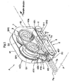
- the transfer tool A is mainly provided with a transfer tool main body 1 having a transfer head H that can hold the tape glue T and can contact the tape glue T with the paper slip P and a transferred object receiver 2 accompanied by this transfer tool main body 1.
- a word “forth” indicating a position or a direction indicates the side where the transfer head H of the transfer tool A is located, and a word “back” indicates the opposite side of the side where the transfer head H is located in a longitudinal direction of the transfer tool A.
- a word “back and forth direction” indicates the longitudinal direction of the transfer tool A.
- a word “upper” indicates the side where the transfer tool main body 1 is located in the transfer tool A
- a word “lower” indicates the side where the transferred object receiver 2 is located in the transfer tool A.
- the transfer tool main body 1 is mainly provided with a refill cartridge 3 holding the tape glue T and a case 4 detachably housing this refill cartridge 3 therein.
- the refill cartridge 3 is mainly configured by an inside plate 31 that rotatably supports a winding off spool SP1 and a rolling up spool SP2, respectively. At a front end portion of this inside plate 31, the transfer head H is rotatably supported.
- the inside plate 31 is made of, for example, a thin plate made of a synthetic resin, and according to the present embodiment, it is assumed that the inside plate 31 is formed in the shape of an substantially egg seen from the side, front end side of which is elongated obliquely downward.
- Each of the winding off spool SP1 and the rolling up spool SP2 is shaped in a substantially tubular form and guard portions are integrally provided at the both ends thereof, and a through hole is formed along axial direction.
- a concavo-convex portion shaped in a saw teeth seen from a flat surface is provided at the opposite position of the rolling up spool SP2 of the inside plate 31, and a nail portion (not illustrated) protruded in a direction orthogonal to the inside plate 31 is provided at the guard portion of the rolling up spool SP2. Then, due to the engagement between the concavo-convex portion and the nail portion, the rolling up spool SP2 is set so as to be rotated only in one direction. In other words, by the concavo-convex portion and the nail portion, a reverse rotation preventing mechanism (ratchet) for preventing the reverse rotation of the rolling up spool SP2 is configured.
- a reverse rotation preventing mechanism for preventing the reverse rotation of the rolling up spool SP2 is configured.
- the concavo-convex portion may be formed at the region opposed to the winding off spool SP1 of the inside plate 31, and in relation to this concavo-convex portion, the nail portion may be provided at the guard portion of the winding off spool SP1 so as to prevent the reverse rotation of the winding off spool SP1.
- a slit 31c shaped in a partial arc seen from the side is formed at the region where the concavo-convex portion is attached in the rolling up spool SP2.
- the transfer head H has a transfer roller RT that can be rotated upon transfer on the paper slip P of the tape glue T.
- This transfer roller RT is formed by a cushion material that can be elastically deformed a little by the externally applied force. Then, in the vicinity of the front end portion of the inside plate 31, an orthogonal chip 311 elongated by a predetermined dimension in a direction orthogonal to the inside plate 31 and a parallel chip 312 elongated from the front end portion of this orthogonal chip 311 approximately in parallel with the inside plate 31 are integrally provided.
- the transfer roller RT is set so as to be rotated around the rotational support shaft ST.
- the front end portion of the transfer head H indicates the front end portion of a transfer face RTa that is a region contacting the paper slip P upon transfer that transfers the tape glue T in the transfer roller RT. This transfer face RTa can be rotated upon transfer.
- tubular portions 312b and 31d are provided, that are evaginated toward the outside direction respectively, and these tubular portions 312b and 31d are set so as to be fit in fitting portions 419 and 437 formed on respective outside plates 41 and 43 to be described later, respectively. Further, according to the present embodiment, these tubular portions 312b and 31d are provided so as to be related to the through holes where the side end portions of the rotational support shaft ST can be inserted, respectively.
- the case 4 is mainly provided with a first outside plate 41 that is one outside wall of the transfer tool main body 1 and a second outside plate 43 opposed to this first outside plate 41 that is the other outside wall of the transfer tool main body 1.
- the first outside plate 41 is shaped in a thin plate, for example, made of a synthetic resin, and according to the present embodiment, the first outside plate 41 is shaped in an approximately rectangle seen from the side with a rounded corner.
- a winding off gear G1 for rotatably driving the winding off spool SP1 and the rolling up spool SP2 and a rolling up gear G2 having a smaller diameter than that of the winding off gear G1 and being engaged with the winding off gear G1 are formed so as to be attached thereon.
- the winding off gear G1 is attached on the inside face of the first outside plate 41 by inserting a shaft 41a formed slightly forward from the approximately center part in the back and forth direction of the first outside plate 41 into a through hole formed on the center part of the winding off gear G1 and then, attaching a core C1 to this shaft 41a so as not to fall therefrom.
- the rolling up gear G2 integrally has a core C2 and the rolling up gear G2 is attached on the inside face of the first outside plate 41 so as not to fall therefrom by inserting a shaft 41b formed at the rear end side of the first outside plate 41 into a through hole formed on the center part of the rolling up gear G2.
- a front periphery portion 413, an upper periphery portion 414, a rear periphery portion 415, and a lower periphery portion 416 are continuously and integrally provided, that are elongated in a direction approximately orthogonal to the first outside plate 41 from the region except for the lower end portion at the front edge and the front end portion at the lower edge in the periphery of the first outside plate 41.
- a part of the lower periphery portion 416 is set discontinuously and at this region, a second auxiliary roller R2a of the present invention is attached via a fixing member 42 shaped in an approximately house shoe seen from the plane face.
- the fixing member 42 is integrally molded provided with a pair of opposing chips 421 and a couple chip 422 with the end portions of these opposed chips 421 continued (refer to Fig. 2), and by inserting a projection portion (not illustrated) protruded from the other end portion of each opposed chip 421 into an inserted concave portion (not illustrated) formed on the first outside plate 41, the fixing member 42 is firmly fixed on the first outside plate 41.
- Insertion holes are formed so as to be opposed mutually on the couple chip 422 of this fixing member 42 and the first outside plate 41 and the side end portions of a rotational support shaft S2a of the second auxiliary roller R2a are inserted into these insertion holes, respectively so as to set the second auxiliary roller R2a rotatably around the rotational support shaft S2a.
- this second auxiliary roller R2a is formed by a cushion material that can be elastically deformed a little by the force added from the outside.
- an elongated chip 417 elongated further downward of the lower periphery portion 416 is integrally provided (refer to Figs. 5. Fig.
- Fig. 5(a) shows a substantial part of Fig. 3
- Fig. 5(b) shows the substantial part of Fig. 4.
- the elongated chip 417 is represented with a pattern and a screw V to be described later is omitted).
- a shaft 418 that is protruded in a direction orthogonal to the elongated direction of the elongated chip 417 is provided (refer to Fig. 2 and Fig. 5).
- This shaft 418 is formed in an approximately column shape and is formed in an approximately ellipse coin shape seen from the side with an upper edge portion 418a and a lower edge portion 418b seen from the side cut approximately parallel.
- These upper edge portion 418a and lower edge portion 418b are the opposed edge portions of the present invention that are formed approximately in parallel with each other seen from the side.
- a distance between the upper edge portion 418a and the lower edge portion 418b namely, a height dimension between the upper edge portion 418a and the lower edge portion 418b of the shaft 418 seen from the side are set to be smaller than the diameter of the shaft 418.
- the elongated direction of the upper edge portion 418a and the lower edge portion 418b of the shaft 418 is set differently from the transfer direction.
- the lower periphery portion 416 of the first outside plate 41 approximately in parallel with the transfer direction and the upper edge portion 418a and the lower edge portion 418b of the shaft 418 are set to be directed forward (the direction of the reverse transfer) at about 15 degrees.
- this shaft 418 is integrally provided on the elongated chip 417, however, the shaft that is a different member from the elongated chip 417 may be integrally attached to the elongated chip 417.
- a concave portion 41A made by caving a part of a rear edge region of the first outside plate 41 toward the front side is formed, and an engaging hole 41a with which an engaging chip 43a disposed on a second outside plate 43 to be described later is engaged is formed on the concave portion 41A (refer to Fig. 2).
- a fitting portion 419 evaginated toward the inside direction is provided.
- This fitting portion 419 is formed so as to be fit the inner circumference and the outer circumference of the tubular portion 312b provided on the inside plate 31 at the same time.
- a latching chip 41K shaped in a fish hook that is protruded toward a direction orthogonal to the first outside plate 41 is provided, and this latching chip 41K and a latching hole 43K formed at the second outside plate 43 to be described later are set so as to be latched each other.
- the second outside plate 43 is formed in a thin plate, for example, made of a synthetic resin as same as the first outside plate 41.
- the shape seen from the side of the second outside plate 43 is set so as to approximately correspond to the shape seen from the side of the first outside plate 41, and a notch 431 that is formed in approximately same shape as the shaped seen from the side of the fixing member 42 is formed on the approximately center part of the lower end portion in order to avoid the interference with the fixing member 42 provided on the first outside plate 41.
- a fitting concave portion 432 concaved on the outside face side so as to be thinner than the other area is formed approximately corresponding to the shape seen from the side of the inside plate 31 (refer to Fig. 2).
- the rolling up spool SP2 is rotated inserting an appropriate tool having a sharp region at its front end portion such as a driver and a pen or a writing material or the like in a concave portion SP2a intermittently provided along a circumferential direction on the outside face of the rolling up spool SP2 from this slit 432a and the slit 31c formed on the inside plate 31, in accordance with this, the winding off spool SP1 is also rotated in conjunction with this, so that loose of the tape glue T including the tape main body Ta in the transfer tool main body 1 can be adjusted.
- a front periphery portion 433, an upper periphery portion 434, a rear periphery portion 435, and a lower periphery portion 436 elongated from the region except for the lower end portion at the front edge and the front end portion at the lower edge to a direction approximately orthogonal to the second outside plate 43 are continuously and integrally provided.
- a fitting portion 437 evaginated toward the outside direction is provided.
- This fitting portion 437 is formed so as to be fit the inner circumference and the outer circumference of the tubular portion 31d provided on the inside plate 31 of the refill cartridge 3 at the same time.
- a concave portion 43A concaved in the front end side is also formed on one end at the rear edge region of the second outside plate 43 corresponding to the concave portion 41A formed on the first outside plate 41, and on this concave portion 43A, the engaging chip 43a that is protruded toward the same direction as the rear periphery portion 435, namely, a direction orthogonal to the second outside plate 43 and is engaged with the engaging hole 41a formed on the concave portion 41A of the first outside plate 41 is provided.
- the engaging chip 43a of the second outside plate 43 is engaged with the engaging hole 41a of the first outside plate 41.
- the engagement region of the engaging chip 43a and the engaging hole 41a functions as a hinge mechanism, and the first outside plate 41 and the second outside plate 43 are set so as to relatively rotate using this engaging regions as a supporting point.
- the case made by integrally assembling the outside plates 41 and 43 is set so as to rotate between a closing position (C) that approximately closes the space between the first outside plate 41 and the second outside plate 43 by abutting or closing respective periphery portions 413, 414, 415, and 416 of the first outside plate 41 against or to respective periphery portions 433, 434, 435, and 436 of the second outside plate 43 and a release position (not illustrated) where the first outside plate 41 and the second outside plate 43 are located approximately linearly and respective inside spaces are released.
- a closing position (C) that approximately closes the space between the first outside plate 41 and the second outside plate 43 by abutting or closing respective periphery portions 413, 414, 415, and 416 of the first outside plate 41 against or to respective periphery portions 433, 434, 435, and 436 of the second outside plate 43
- a release position not illustrated
- latching means for latching the first outside plate 41 and the second outside plate 43 each other at the closing position (C) is configured.
- the procedure to attach the refill cartridge 3 in the case 4 made by assembling the first outside plate 41 and the second outside plate 43 having such a structure will be described.
- the first outside plate 41 and the second outside plate 43 that are assembled so as to be rotatable relatively are set at the release position.
- the refill cartridge 3 is fitted in the first outside plate 41 so as to engage the inner circumference of the winding off spool SP1 and the outer circumference of the core C1 and to engage the inner circumference of the rolling up spool SP2 and the outer circumference of the core C2.
- the tubular portion 312b provided on the parallel chip 312 of the refill cartridge 3 and the fitting portion 419 provided on the first outside plate 41 are fitted each other.
- the tubular portion 31d provided on the inside plate 31 of the refill cartridge 3 and the fitting portion 437 provided on the second outside plate 43 are fitted each other, and the outside face of the inside plate 31 is fitted in the fitting concave portion 432 formed on the second outside plate 43 abutting against it or near it, so that the refill cartridge 3 is stably held between the first outside plate 41 and the second outside plate 43.
- the front end portion of the transfer head H namely, the transfer face RTa of the transfer roller RT and the lower end portion of the second auxiliary roller R2a are set so as to be located further below of the lower periphery portions 416 and 436 of the first outside plate 41 and the second outside plate 43 (refer to Figs. 3 to 5).
- the transferred object receiver 2 is mainly provided with a base 5 having a bearing portion 511 formed so as to support the shaft 418 that is disposed on the elongated chip 417 of the first outside plate 41 and an arm portion 6 set to be capable of performing the balancing operation with respect to the base 5.
- the base 5 is set so that its back and forth width dimension is slightly shorter than that of the transfer tool main body 1 and a step portion 5D is formed at the approximately center part in the back and forth direction so that the height dimension of the area ranging from the approximately center part in the back and forth direction to the front end portion is smaller than that of the area ranging from the approximately center part in the back and forth direction to the rear end portion.
- the region at the rear end side from this step portion 5D is referred to as a posterior portion 51
- the region at the front end side from this step portion 5D is referred to as an anterior portion 52.
- the bearing portion 511 is formed on the posterior portion 51.
- This bearing portion 511 has a first large diameter part 511a and a second large diameter part 511b having slightly larger diameters than that of the shaft 418 at the regions that are separated at a predetermined distance in the back and forward direction, and has a groove 511c elongated in the back and forward direction so as to communicate these diameter parts 511a and 511b with each other.
- the shaft 418 can be inserted through the groove 511c.
- the height dimension of the groove 511c is set to be slightly larger than the height dimension between the upper edge portion 418a and the lower edge portion 418b of the shaft 418 seen from the side (namely, the distance between the upper edge portion 418a and the lower edge portion 418b) and be slightly smaller than the diameter of the shaft 418 (refer to Fig. 5). Then, corresponding this bearing portion 511 to the formed region, a space of a predetermined width dimension is formed between exterior wall parts 512 configuring the opposite exterior walls at the posterior portion 51 of the base 5.
- an elastic member 53 is attached not to be detachable, which has an opening portion 53 the shape of which shape seen from the side approximately coincides with the shape of the posterior part 51 seen from the side, the shape of which is approximately the same as that of the bearing portion 511 (refer to Fig. 2 and Fig. 5).
- the opening portion 53a is formed in the approximately U shape seen from the side opened backward. Only the front end portion of this elastic member 53 is firmly fixed on the base 5, so that the regions other than the front portion are elastically deformed a little by the force given from the outside.
- the front end portion and the center part approximately coincide with the first large diameter parts 511a and the groove 511c and the rear end portion has an opening dimension that approximately coincides with that of the groove 511c, so that the rear end portion of the elastic member 53 is exposed in the second large diameter part 511b as seen from the side (refer to Fig. 5 and Fig. 7 to be described later).
- a protrusion portion 521 protruding upward at the approximately center part in the back and forth direction of the anterior portion 52, and at the front end portion of this protrusion portion 521 a pair of convex portions 521a are formed in a circular form seen from the side that are protruded outside, respectively.
- the arm portion 6 is arranged in the anterior portion 5 of the base 5 to form a fitting hole 61a into which a convex portion 521a provided at the anterior portion 52 of the base 5 is fitted.
- the first auxiliary roller R1 that can rotate in conjunction with the transfer roller RT upon transfer is provided at the front end portion of the arm portion 6, and the second auxiliary roller R2b that can rotate in conjunction with the second auxiliary roller R2a that is provided on the transfer tool main body 1 upon transfer is provided at the rear end portion of the arm portion 6.
- first auxiliary roller R1 and the second auxiliary roller R2b are set to be rotatable around the rotational support shafts S1 and S2b.
- These first auxiliary roller R1 and the second auxiliary roller R2b are formed by a cushion material that can be elastically deformed, and the upper edge portions of respective rollers R1 and R2 are set to be located upward from the upper edge of the arm portion 6.
- the arm portion 6 and the base 5 are integrally assembled.
- a gap 2S with a predetermined height dimension is formed between the lower edge of the arm portion 6 and the upper edge at the anterior portion 52 of the base 5 (refer to Fig. 3 or the like), and the arm portion 6 is made to be capable of performing the balancing operation with respect to the base 5 using the fitting region of the convex portion 521a and the fitting hole 61a as a supporting point.
- the arm portion 6 and the base 5 are set so that the upper edge of the arm portion 6 approximately coincides with the upper edge of the posterior portion 51 of the base 5.
- an operation lever L that can rotate the first auxiliary roller R1 by a certain angle by the predetermined operational force is provided.
- the first auxiliary roller R1 is moved by a certain dimension into the reverse transfer direction.
- the transfer roller RT is also moved by a certain dimension into the reverse transfer direction to draw the tape glue T from the transfer face RTa of the transfer roller RT.
- the tape glue T can be sent to the paper slip P in a certain dimension.
- an elongated face portion (not illustrated) elongated to the releasing side of an insertion space AS is formed on the upper face of the arm portion 6, the paper slip P is supported by this elongated face portion upon transfer, and the paper slip P can be easily inserted in the insertion space AS.
- transfer start position display means for showing a transfer start position of the glue Tb on the paper slip P may be provided.
- the transfer start position display means on the upper face of the elongated face portion, one configured by a transfer start position display line provided approximately along the extended line of the rotational support shaft ST of the transfer roller RT and a mounting instruction display provided just on the back of this transfer start position display line may be available. It is preferable that any of the transfer start position display line and the mounting instruction display is in the form of a shallowly engraved mark on the upper face of the elongated face portion.
- a straight line and the shape of the paper slip may be employed, respectively.
- the ones printed on the upper face of the elongated face portion or the ones to which a seal is pasted may be available. In this way, the assured transfer operation and the usage direction free from errors are suggested to the user.
- the shaft 418 that is provided on the first outside plate 41 of the transfer tool main body 1 is inserted into the bearing portion 511 formed on the base 5 of the transferred object receiver 2. Specifically, inserting the shaft 418 in the second large diameter part 511b formed at the rear edge portion side in the bearing portion 511 and screwing the screw V screwed in a screw hole formed on the shaft 418 in this state, the transferred object receiver 2 is integrally assembled with the transfer tool main body 1 so that the transferred object receiver 2 cannot be pulled out from the transfer tool main body 1. Further, according to the present embodiment, a so-called pleated screw is used as the screw V so as to simplify the screwing operation.
- the transferred object receiver 2 is set to be rotatable around the transfer tool main body 1 using a pivoting point between the shaft 418 and the second large diameter part 511b as a supporting point between an unused position (P) where the transferred object receiver 2 is separated from the transfer head H of the transfer tool main body 1 at a predetermined distance and a using position (O) where the transferred object receiver 2 abuts against or is near the transfer head H of the transfer tool main body 1.
- the upper edge portion 418a and the lower edge portion 418b of the shaft 418 are inclined with respect to the lower periphery portions 416 and 436 of respective outside plates 41 and 43 for a predetermined angle (in the present embodiment, about 15 degrees), so that the transferred object receiver 2 is inclined with respect to the transfer tool main body 1 for a predetermined angle (in the present embodiment, about 15 degrees) (refer to Fig. 5B).
- This state is defined as the initial state.
- the shaft 418 abuts against the inner face of the opening portion 53a of the elastic member 53 that is disposed at the base 5 in the second large diameter portion 511b and thereby, the elastic member 53 is elastically deformed so that the opening height dimension of the opening portion 53a of the elastic member 53 is made large (refer to Fig. 5 (a)).
- the elastically deforming parties are configured so as to accumulate the urging force urged to the direction separating the transferred object receiver 2 from the transfer tool main body 1 by elastically deforming the elastically deforming part due to the pressure welding force between the upper edge portion 418a, the lower edge portion 418b and the inside face of the opening portion 53a.
- the force is acted into a direction returning the unused position (P) by a restoring force of the elastic member 53.
- the elongated chip 417 disposed at the first outside plate 41 of the transfer tool main body 1 abuts against a part of the arm portion 6 of the transferred object receiver 2 (refer to Fig. 5(a)) so as to prevent the transfer tool main body 1 and the transferred object receiver 2 from moving close each other for a predetermined distance or more.
- the elongated chip 417 functions as the regulating means of the present invention to prevent the transfer tool main body 1 and the transferred object receiver 2 from moving close each other for a predetermined distance or more upon transfer.
- the transfer roller RT disposed at the transfer tool main body 1 and the first auxiliary roller R1 disposed at the transferred object receiver 2 are opposed each other abutting or coming close together; at the position separated from the opposed position of these transfer roller RT and the first auxiliary roller R1 at a predetermined distance in the transfer direction, the second auxiliary roller R2a disposed at the transfer tool main body 1 and the second auxiliary roller R2b disposed at the transferred object receiver 2 are opposed with each other abutting or coming close together; the insertion space AS is formed between the transfer tool main body 1 and the transferred object receiver 2, through which the paper slip P can be inserted.
- the transfer face RTa of the transfer roller RT and a backing face R1a of the first auxiliary roller R1 are opposed with each other abutting or coming close together; the lower edge portion of the second auxiliary roller R2a disposed at the transfer tool main body 1 and the upper edge portion of the second auxiliary roller R2b disposed at the transferred object receiver 2 are opposed with each other abutting or coming close together.
- the insertion space AS is formed between the lower edge portions 416 and 436 of the first outside plate 41 and the second outside plate 43 and the upper edge portions of the base 5 and the arm portion 6. As shown in Fig.
- one side of the insertion space AS is approximately closed by the elongated chip 417 and the insertion space AS is continuously opened in three directions, namely, the transfer direction, the direction of the other side that can be opposed to the elongated chip 417, and the reverse transfer direction.
- the transferred object receiver 2 is located at a transfer head covered position (Q) where the transferred object receiver 2 can cover the front end portion of the transfer head H. If the shaft 418 is slidably moved toward the first large diameter portion 511a along the elongated direction of the groove 511c of the bearing portion 511 from this state, as shown in Fig. 7, the transferred object receiver 2 becomes a transfer head exposed position (R) where the front end portion of the transfer head H is exposed.
- the slidable moving mechanism according to the present invention is configured, in which the transferred object receiver 2 can be slidably moved with respect to the transfer tool main body 1 between the transfer head covered position (Q) and the transfer head exposed position (R).
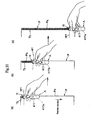
- the user puts his or her thumb on the transfer tool main body 1 and puts other fingers on the transferred object receiver 2 so as to hold the transfer tool A.
- the user holds transfer tool A so that the elongated chip 417 of the transfer tool main body 1 is located at the user' s palm' s side.
- the user brings the paper slip P and the transfer tool A close together so that the edge Pa of the paper slip P abuts against or is near the elongated chip 417 of the transfer tool main body 1.
- the operational force is given in a direction to bring the transferred object receiver 2 close to the transfer head H.
- the transferred object receiver 2 is rotatably moved with respect to the transfer tool main body 1 to be located at the using position (O).
- the elongated chip 417 abuts against a part of the arm portion 6, the transfer roller RT and the first auxiliary roller R1 are opposed with each other sandwiching the paper slip P, and the second auxiliary rollers R2a and R2b are opposed with each other sandwiching the paper slip P.
- the transfer face RTa of the transfer roller RT is brought into contact with the surface of the paper slip P to slidably move the transfer tool A into the transfer direction.
- the paper slip P is configured to be guided to the elongated chip 417 so as to be capable of moving within the insertion space AS (refer to Fig. 6).
- the elongated chip 417 also functions as the guide mans according to the present invention.
- the first auxiliary roller R1 is set to be synchronously rotated in conjunction with the transfer roller RT while bringing the backing face R1a into contact with the rear surface of the paper slip P and a pair of second auxiliary rollers R2a and R2b are synchronously rotated due to the friction force with the paper slip P, so that the stable transfer operation can be carried out.
- the first auxiliary roller R1 and the second auxiliary roller R2b provided at the arm portion 6 are appropriately connected to or separated from the transfer roller RT and the second auxiliary roller R2a provided on the transfer tool main body 1, and at least the backing face R1a of the first auxiliary roller R1 may contact the rear face of the paper slip P upon transfer. Further, upon transfer, the tape glue T sandwiched between the transfer face RTa and the paper slip P is sent from the winding off spool SP1 that is rotated together with the winding off gear G1 by the frictional force.
- the rolling up spool SP2 is rotated together with the rolling up gear G2 that is reversely rotated in accordance with the winding off gear G1, so that the tape main body Ta having no glue Tb on its one side will be winded by the rolling up spool SP2.
- the desirable area on the paper slip P is transferred, by stopping transfer of the operational force into a direction to bring the transferred object receiver 2 close to the transfer tool main body 1, the transferred object receiver 2 is rotatably moved into a direction being separated from the transfer head H by the restoration force (the bias force) of the elastic member 53 provided at the base 5 to be located at the unused position (P).
- the transfer tool A according to the present embodiment also can employ the usage mode that only the transfer tool main body 1 is brought into contact with the paper slip P to transfer the tape glue T on the paper slip P without sandwiching the paper slip P between the transfer tool main body 1 and the transferred object receiver 2.
- the transfer tool A according to the present embodiment also can employ the usage mode that only the transfer tool main body 1 is brought into contact with the paper slip P to transfer the tape glue T on the paper slip P without sandwiching the paper slip P between the transfer tool main body 1 and the transferred object receiver 2.
- the transferred object receiver 2 located at the transfer head covered position (Q) is slidably moved into a back side (the transfer direction) with respect to the transfer tool main body 1 so as to locate the transfer tool A at the transfer head exposed position (R).
- the transfer tool A of the present embodiment can transfer the transfer material on the transferred object in the same usage mode as the well known transfer tool A.
- the transfer tool A may be located at the transfer head covered position (Q).
- the case 4 is located at the releasing position, and detaching the refill cartridge 3 from the case 4, the other refill cartridge 3 may be attached to the case 4.
- the transfer tool A of the present embodiment is provided with the transfer tool main body 1 and the transferred object receiver 2 that can be relatively rotated with respect to this transfer tool main body 1.
- the transfer tool A of the present embodiment is configured to be slidably moved into a predetermined transfer direction while bringing the transfer face RTa of the transfer head H into contact with the paper slip P with the paper slip P sandwiched between the transfer tool main body 1 and the transferred object receiver 2 so as to transfer the tape glue T on the paper slip P. Therefore, it is not necessary to prepare a board such as a table and a desk on which the paper slip P is mounted upon transfer, and the transfer can be easily carried out in any places.
- the present transfer tool can preferably transfer the transfer material on the paper having any specifications and any shapes.
- the paper slip P by inserting the paper slip P in the insertion space AS formed between the transfer tool main body 1 and the transferred object receiver 2 with the transferred object receiver 2 located at the using position (O) and slidably moving the paper slip P into the transfer direction, it may be possible to transfer the tape glue T on the paper slip P.
- the first auxiliary roller R1 that can be rotated in conjunction with the transfer roller RT upon the transfer is provided at the transferred object receiver 2, the transfer operation with the paper slip P sandwiched can be smoothly carried out. Further, since the first auxiliary roller R1 is provided at the position being opposed to the transfer roller RT, the first auxiliary roller R1 can be closely related to the first auxiliary roller R1, so that the stable rotational operation of the first auxiliary roller R1 can be realized.
- first auxiliary roller R1 is configured to have the backing face R1a that is located at the region being opposed to the transfer face RTa of the transfer roller RT and can contact the rear face of the paper slip P upon the transfer so as to relatively connect or separate the backing face R1a to or from the transfer face RTa, bite of the first auxiliary roller R1 into the paper slip P can be improved.
- first auxiliary roller R1 is formed by a cushion material that is elastically deformed in a direction to connect or separate the first auxiliary roller R1 to or from the transfer head H, the bite to the paper slip P of the first auxiliary roller R1 can be further improved.
- the paper slip P can be sandwiched at two places in the insertion space AS. Therefore, it is possible to effectively solve the defect such that the paper slip P is misaligned from the transfer tool A upon the transfer and the rectilinear propagation property of the transfer tool A to the paper slip P can be effectively improved.
- the transferred object receiver 2 is configured so as to be relatively movable with respect to the transfer tool main body 1 between the transfer head covered position (Q) where the front end portion of the transfer head H can be covered and the transfer head exposed position (R) where the front end portion of the transfer head H is exposed. Therefore, in the case of setting the transferred object receiver 2 at the transfer head exposed position (R), the transfer tool A of the present embodiment can be used as same as the known transfer tool, namely, it can be used in the mode that the paper slip P is not sandwiched, so that the transfer tool A of the present embodiment can be used separately depending on the application and the transfer tool A of the present embodiment becomes more practical.
- the slidably moving means which relatively moves the transfer tool A between the transfer head covered position (Q) and the transfer head exposed position (R) by slidably moving the transferred object receiver 2 in the transfer direction or the reverse transfer direction with respect to the transfer tool main body 1, so that the transfer tool A can be located at the transfer head covered position (Q) or at the transfer head exposed position (R) with the simple operation.
- the slidably moving means is configured from the shaft 418 provided at the transfer tool main body 1 and the bearing portion 511 formed on the transferred object receiver 2 so as to support the shaft 418; the groove 511c through which the shaft 418 can be inserted and which is elongated to the transfer direction or the reverse transfer direction is formed on the bearing portion 511; and the transferred object receiver 2 is configured so as to slidably move with respect to the transfer tool main body 1 between the transfer head covered position (Q) and the transfer head exposed position (R) by slidably moving the shaft 418 along the elongated direction of the grove 511c; so that the transfer tool A can be located at the transfer head covered position (Q) or the transfer head exposed position (R) with the simple configuration and the simple operation and this makes the transfer tool A to be excellent in usability.
- the regulating means to prevent the transfer tool main body 1 and the transferred object receiver 2 from moving close each other for a predetermined distance or more is upon transfer provided, it is possible to prevent so-called bite and the deformation and the damage of the member that may occur when the transfer tool main body 1 and the transferred object receiver 2 come close together beyond necessity. Further, since the dimension to sandwich the paper slip P is made constant, the transfer operation can be smoothly carried out.
- the regulating means uses the elongated chip 417 that is provided at the transfer tool main body 1 and is elongated to the other side and the elongated chip 417 can abut against the transferred object receiver 2 by priority upon the transfer, it is possible to assuredly prevent the transfer tool main body 1 and the transferred object receiver 2 from coming close together for a predetermined distance or more employing the very simple structure.
- this elongated chip 417 functions as the guide means that can abut against the edge portion Pa of the paper slip P when the paper slip P is inserted in the insertion space AS and the paper slip P is configured to be guided by this guide means, namely, the elongated chip 417 so as to be movable in the insertion space AS. Therefore, by abutting the edge portion Pa of the paper slip P against the elongated chip 417, the insertion depth dimension of the paper slip P with respect to the transfer tool A is made constant. By performing the transfer with this insertion depth dimension kept, the transfer trace that is approximately in parallel with the edge portion Pa of the paper slip P can be transferred like drawing it. In addition, since the elongated chip 417 can close one side along the transfer direction in the insertion space AS, it is possible to keep the dimension of sandwiching the paper slip P and the insertion depth dimension of the paper slip P into the insertion space AS constant.
- the transfer material such as tape glue may be transferred on the transferred object such as a paper slip.
- a transfer tool employing a transfer head provided with a face plate having the transfer face sliding on the surface of the transferred object without rotating upon transfer may be considerable. According to such a transfer tool, as compared to the embodiment using the transfer roller, it is not necessary to attach the rotational support shaft, so that the structure can be simplified and the number of parts can be reduced.
- first auxiliary roller at the position opposed to the transfer roller and the first auxiliary roller may be in conjunction with the transfer roller upon transfer.
- two and more pairs of the second auxiliary rollers may be provided, which are opposed to the side of the transfer tool main body and the side of the transferred object receiver.
- a first endless track mechanism winding a crawler track between at least one second auxiliary roller and at least one transfer roller may be provided at the transfer tool main body. According to such an embodiment, it is possible to smoothly carry out the transfer operation by using the crawler track rotated in accordance with the synchronization rotational operation of each roller. In this case, it is preferable that the crawler track is winded so as not to fall on the transfer face of the transfer roller. Further, if a second endless track mechanism winding a crawler track between at least one second auxiliary roller and at least first auxiliary roller is provided at the transferred object receiver, it is possible to smoothly carry out the transfer operation in a stable state.
- the insertion space may be continuously opened to three directions, namely, at least a predetermined transfer direction, a reverse transfer direction, and a direction that is orthogonal to the transfer direction and the reverse transfer direction. Further, the insertion space may be continuously opened to four directions, namely, the transfer direction, the reverse transfer direction, and the both directions that are orthogonal to the transfer direction and the reverse transfer direction.
- the transferred object receiver is configured so as to be relatively movable with respect to the transfer tool main body between the transfer head covered position and the transfer head exposed position
- the embodiment of using a rotatably moving mechanism to relatively move the transferred object receiver between the transfer head covered position and the transfer head exposed position by rotatbly moving the transferred object receiver in a predetermined direction with respect to the transfer tool main body may be adopted.
- the rotatably moving mechanism is configured by the shaft disposed at the transfer tool main body and the bearing portion formed so as to rotatably support the shaft at the transferred object receiver and the transferred object receiver may be configured so as to rotatably move with respect to the transfer tool main body between the transfer head covered position and the transfer head exposed position using the pivoting point of the shaft and the bearing portion as a support point.
- the transferred object receiver may be located at the transfer head exposed position and the operation becomes simple.
- the elongated chip configuring the regulating means and/or the guide means may be provided at the transferred object receiver and may be elongated toward the transfer tool main body. Further, the regulating means and the guide means may be formed by different members, respectively.
- an inward face located at least the side of the insertion space in the elongated chip and the first virtual standing face passing through the transfer face of the transfer head may be set to form a blunt angle opening to the transfer direction.
- a defect that the track of transfer generated when the user turns his or her wrist upon transfer in the case that an inward face 417a of the elongated chip 417 and the first virtual standing face vir1 that is a virtual standing face passing through the transfer face of the transfer head H are approximately orthogonal to each other, describes an arc, and the rectilinear propagation property upon the transfer can be improved.
- Fig. 9 it is possible to prevent a defect that the track of transfer generated when the user turns his or her wrist upon transfer in the case that an inward face 417a of the elongated chip 417 and the first virtual standing face vir1 that is a virtual standing face passing through the transfer face of the transfer head H are approximately orthogonal to each other, describes an arc, and the rectilinear propagation property upon the transfer can be
- the first virtual standing face vir1 is orthogonal to the transfer direction and the angle formed by the inward face 417a and the first virtual standing face vir1 may be set to be the blunt angle opening to the transfer direction.
- the angle formed by the inward face 417a and the first virtual standing face vir1 may be set to be the blunt angle opening to the transfer direction.
- the elongated chip is provided at the transfer tool main body (not illustrated) and the outside plate that is an outside wall of the transfer tool main body is set to be approximately in parallel with the inward face of the elongated chip, with the transferred object such as a paper slip sandwiched between the transfer tool main body and the transferred object receiver, at least the outside plate of the transfer tool main body is apparently made in approximately parallel with the edge portion of the paper slip. Even if the inward face is inclined to the first virtual standing face for a predetermined angle, the user can perform the transfer operation without uncomfortable feeling.
- first auxiliary roller cradle for supporting the rotational support shaft of the first auxiliary roller on the transferred object receiver and configuring this first auxiliary roller cradle so as to be elastically deformed in a direction connecting or separating this first auxiliary roller cradle to and from the transfer head, it is preferably possible to close or separate the transfer head and the first auxiliary roller that opposed corresponding to the thickness or the like of the transferred object.
- the first auxiliary roller cradle As the specific embodiment of the first auxiliary roller cradle, the one is available, in which a slit is formed around the first auxiliary roller cradle within a range that the first auxiliary roller cradle and the transferred object receiver are not separated and the first auxiliary roller cradle can move up and down with respect to the transferred object receiver using a continuous part continued to the transferred object receiver as a support point via this slit.
- At least one second auxiliary roller may be provided on the transferred object receiver, and the second auxiliary roller cradle supporting the rotational support shaft of the second auxiliary roller may be formed so as to be elastically deformed to a direction connecting or separating to or from the other second auxiliary roller that is provided at the transfer tool main body so that the second auxiliary roller cradle is opposed to one second auxiliary roller.
- the one may be available, in which a slit is formed around the second auxiliary roller cradle within a range that the second auxiliary roller cradle is not separated from the transferred object receiver and the second auxiliary roller cradle can move up and down with respect to the transferred object receiver using a continuous part continued to the transferred object receiver as a support point via this slit.
- the tape glue as the transfer material may be any of solid or liquid glue and the present transfer tool may be applied a general transfer material to be transferred on the transferred object such as various tapes including a correction tape, an adhesive tape, and an incohesive tape, and an adhesive or the like.
- the transfer tool since it is possible to use the transfer tool in the innovative and unconventional embodiment such that the transfer is carried out with the transferred object such as paper sandwiched between the transfer tool main body and the transferred object receiver, a board such as a table and a desk on which the transferred object is mounted are not needed upon transfer and the transfer can be easily carried out in any places. As a result, the operation to further mount the underlay on the surface of the table or the like is naturally unnecessary, so that the transfer operation can be immediately performed and this improves the practical utility of the present transfer tool.
- the specification and the shape of the transferred object that can be transferred are not limited to the inside dimension of the insertion space. Therefore, by transferring the transferred object inserted from the reverse transfer directional side to the transfer directional side, the transfer can be preferably made on the transferred object with any specification and any shape. Further, the present transfer tool also can transfer the transfer material on the transferred object by inserting the transferred object in the insertion space formed between the transfer tool main body and the transferred object receiver with the transfer tool main body brought close to the transferred object receiver in advance, and sliding and moving the transferred object to the transfer direction. The present transfer tool can be applied to various usage modes depending on the application.
Landscapes
- Adhesive Tape Dispensing Devices (AREA)
- Ink Jet (AREA)
- Decoration By Transfer Pictures (AREA)
Abstract
Description
- The present invention relates to a transfer tool used for transferring a transfer material on a transferred object such as paper.
- Conventionally, various transfer tools have been created, which are used when transferring a transfer material such as solid or liquid glue, a tape such as an adhesive tape and an incohesive tape, and an adhesive or the like on a transferred object such as paper. It is usually the case that the transfer tool for transferring such a transfer material is provided with a case holding the transfer material therein and a transfer head for transferring the transfer material held in the case to the transferred object. This transfer head serves to transfer the transfer material on the transferred object contacting the transferred object. Such a transfer tool is configured so as to transfer the transfer material on the surface of the transferred object when a user has a holder in his or her hand to slidably move a transfer head on the transferred object with the transfer head contacting the surface of the transferred object (for example, refer to a patent document 1)
Patent document 1:JP-A-2002-178694 - However, according to the conventional transfer tool, in order to carry out the stable transfer operation, the transfer is performed with the transferred object such as paper mounted on a flat face plate such as a desk and a work table, and this generates a defect that a place where the transfer tool can be used is limited. In addition, in order to prevent the desk and the work table or the like from getting dirty when the transfer material such as glue runs off the edge of the transferred object in advance, an underlay may be further mounted on the flat face plate such as the desk or the work table and the transferred object may be mounted thereon. In this case, the work before the transfer material is transferred on the transferred object is troublesome, so that this involves a problem such that the transfer operation cannot be carried out immediately and a practical utility is lacked.
- The present invention has been made taking the foregoing problems into consideration and an object of which is to provide a transfer tool that can be preferably used without a table such as a desk and can easily carry out the transfer operation in any places.
- In other words, the present invention may comprise a transfer tool used for transferring a transfer material on a transferred object such as paper, including: a transfer tool main body having a transfer head that can bring at least the transfer material into contact with the transferred object; and a transferred object receiver that is accompanied by the transfer tool main body; wherein the transfer head has a transfer face that is a region contacting the transferred object and transferring the transfer material when transferring the transfer material on the transferred object; an insertion space is formed between the transfer tool main body and the transferred object receiver, in which the transferred object can be inserted; the transfer head is positioned so that at least the transfer face is exposed in the insertion space; and the transfer material is transferred on the transferred object by slidably moving the transfer face to a predetermined transfer direction while bringing the transfer face into contact with the transferred object with the transferred object inserted in the insertion space and the transferred object sandwiched between the transfer tool main body and the transferred object receiver.
- In this case, "a transfer direction" means a direction for moving the transfer tool to the transferred object in the case of using the transfer tool with the transferred object sandwiched between the transfer tool main body and the transferred object. According to such a transfer tool, a usage mode that is not applied to the conventional transfer tool, namely, a usage mode that the transfer is carried out with paper sandwiched between the transfer tool main body and the transferred object receiver can be employed. Therefore, it is not necessary to use a board such as a table and a desk on which the transferred object is mounted upon transfer and the transfer tool according to the present invention can easily transfer the transfer material on the transferred object in any times and any places. As a result, it is natural that the work to further mount the underlay on the surface of the table or the like is not needed, so that it is preferable that the transfer operation can be carried out immediately.
- Particularly, if the insertion space is continuously opened to three directions, namely, at least a predetermined transfer direction, a reverse transfer direction, and a direction that is orthogonal to the transfer direction and the reverse transfer direction, a specification and a shape of the transferred object that can be transferred are not limited to the inside measure of the insertion space. Therefore, by relatively sliding and moving the transferred object inserted from the reverse transfer direction to the transfer direction with respect to the transfer tool, the present transfer tool can preferably transfer the transfer material on the transferred object having any specifications and any shapes. In addition, since the present transfer tool has such an insertion space, the present transfer tool also can transfer the transfer material on the transferred object by inserting paper into the insertion space that is formed between the transfer tool main body and the transferred object receiver with the transfer tool main body brought close to the transferred object receiver in advance, and sliding and moving the paper to the transfer direction. In this case, the transfer tool can perform the transfer operation more simply since the operation to grasp the transfer tool is not necessary.
- Further, if the transfer material is transferred on the transferred object by sliding the transfer face of the transfer head on the surface of the transferred object upon transfer, as compared to the usage mode that a transfer roller is disposed at the transfer head, the configuration of the transfer tool can be effectively simplified and the number of parts thereof can be effectively reduced.
- On the other hand, if the transfer head includes a transfer roller having the transfer face that can be rotated upon transfer, it is possible to contact the transferred object and the transfer face more smoothly to improve the transfer property. Particularly, if a first auxiliary roller is provided on the transferred object receiver, which can be rotated in conjunction with the transfer roller upon transfer, it is possible to smoothly carry out the transfer operation with the transferred object sandwiched between the transfer tool main body and the transferred object receiver.
- Further, in order to interlock the transfer roller with the first auxiliary roller with a high probability, the first auxiliary roller may be provided at a position opposed to the transfer roller. In addition, if the first auxiliary roller has a backing face that is a region that can be opposed to the transfer face and can contact the rear face of the transferred object upon transfer and the backing face and the transfer face are relatively connected and separated each other, the backing face and the transfer face are relatively contacted and separated in response to the thickness of the transferred object to be transferred upon transfer, it is possible to bring the backing face and the transfer face into contact with the front surface and the rear surface of the transferred object, respectively, and bite into the transferred object is improved. As a specific embodiment, the embodiment that the transferred object receiver includes a base and at least the first auxiliary roller, and further includes an arm portion that can carry out the balancing operation with respect to the base and the embodiment that the first auxiliary roller cradle supporting a rotational support shaft of the first auxiliary roller is configured so as to be elastically deformed in a direction connecting and separating to and from the transfer head are conceivable. In addition, if the first auxiliary roller is formed by a cushion material that is elastically deformed at least in a direction connecting and separating to and from the transfer head, these advantages can be more effective.
- In addition, if a pair and more of second auxiliary rollers is provided, which are opposed at the side of the transfer tool main body and the side of the transferred object receiver at a position in the insertion space that is different from the opposed position of the transfer roller and the first auxiliary roller, the transferred object is closely related to the transfer tool in at least two places within the insertion space. As a result, it is possible to smoothly move the transferred object and a straight through property to the transferred object of the transfer tool can be effectively improved.
- Further, in order to more smoothly move the transferred object on the transferred object, a first endless track mechanism winding a crawler track between at least one of the second auxiliary roller and the transfer roller may be provided with the transfer tool main body. In addition, if a second endless track mechanism winding a crawler track between at least one of the second auxiliary roller and the first auxiliary roller is provided at the transferred object receiver, the transfer operation can be carried out smoothly with a stable state. Particularly, as the embodiment that can adjust the second auxiliary rollers opposed with each other flexibly in response to the thickness of the like of the transferred object, the embodiment that the transferred object receiver includes a base and at least one of the second auxiliary roller and further includes an arm portion that can carry out the balancing operation with respect to the base or the embodiment that the transferred object receiver includes at least one of the second auxiliary roller and a second auxiliary roller cradle supporting a rotational support shaft of the second auxiliary roller is configured so as to be elastically deformed in a direction connecting and separating to and from the other second auxiliary roller that is provided with the transfer tool main body so as to be opposed to the one second auxiliary roller are conceivable.
- Further, if the transferred object receiver is configured so as to be relatively movable with respect to the transfer tool main body between a transfer head covered position where the front end portion of the transfer head can be covered and a transfer head exposed position where the front end portion of the transfer head is exposed, in the case that the transferred object receiver is set at the transfer head exposed position, the present transfer tool can be used in the same way as the known transfer tool, namely, without sandwiching the transferred object between the transfer tool main body and the transferred object receiver. Therefore, by appropriately changing the usage mode depending on the application, the present transfer tool becomes more practical.
- Specifically, the embodiment provided with a slidably moving mechanism which relatively moves the transferred object receiver between the transfer head covered position and the transfer head exposed position by slidably moving the transferred object receiver in the transfer direction or in the reverse transfer direction with respect to the transfer tool main body is available. As the embodiment of the slidably moving mechanism with a simple structure that can locate the cradle at the transfer head exposed position or at the transfer head covered position by the simple operation, the embodiment that the slidably moving mechanism is configured by a shaft provided at the transfer tool main body and a bearing portion formed on the transferred object receiver so as to support the shaft; a groove is formed on the bearing portion, in which the shaft can be inserted and which is elongated in the transfer direction or in the reverse transfer direction; and the transferred object receiver is configured so as to be slidabely movable with respect to the transfer tool main body between the transfer head covered position and the transfer head exposed position by slidably moving the shaft along the elongated direction of the groove is available.
- In addition, as the other specific embodiment, the embodiment including a rotatably moving mechanism which relatively moves the transferred object receiver between the transfer head covered position and the transfer head exposed position by rotatably moving the transferred object receiver in a predetermined direction with respect to the transfer tool main body is conceivable. In this case, if the rotatably moving mechanism is configured by a shaft provided at the transfer tool main body and a bearing portion formed on the transferred object receiver so as to rotatably support the shaft; and the transferred object receiver is configured so as to be rotatably movable with respect to the transfer tool main body between the transfer head covered position and the transfer head exposed position using a pivoting point between the shaft and the bearing portion as a support point, by rotatabily clearing the transferred object receiver located at the transfer head covered position, the transferred object receiver is located at the transfer head exposed position with the simple operation.
- In addition, if regulating means is provided, which prevents the transfer tool main body and the transferred object receiver from moving close each other for a predetermined distance or more upon transfer, it is possible to prevent so-called bite and deformation and damage of a member that may occur when the transfer tool main body comes close to the transferred object receiver beyond necessity. As the specific embodiment of the regulating means, the embodiment that the regulating means uses an elongated chip that is provided at any one of the transfer tool main body or the transferred object receiver and is elongated to the other one; and the elongated chip abuts against the other one by priority when transferring the transfer material on the transferred object is conceivable. According to such a transfer tool, by using the simple structure, it is possible to surely prevent the transfer tool main body and the transferred object receiver from coming close to each other beyond necessity.
- Further, if guide means is provided, which can abut against the edge portion of the transferred object when the transferred object is inserted in the insertion space and the transferred object is guided by this guide means so as to be movable in the insertion space, by abutting the edge of the transferred object against the guide means, the dimension of the insertion depth of the transferred object with respect to the transfer tool is made constant, so that it is possible to perform transfer approximately in parallel with the edge of the transferred object. As the specific embodiment of the guide means, the embodiment the guide means uses an elongated chip that is provided at any one of the transfer tool main body or the transferred object receiver and is elongated to the other one is available.
- In addition, regulating means may be provided, which prevents the transfer tool main body and the transferred object receiver from moving close each other for a predetermined distance or more upon transfer; the regulating means may function as the guide means that can abut against the edge portion of the transferred object when the transferred object is inserted in the insertion space. Further, the regulating means may use an elongated chip that is provided at any one of the transfer tool main body or the transferred object receiver and is elongated to the other one; the elongated chip may abut against the other one by priority when transferring the transfer material on the transferred object. If the guide means uses the elongated chip, the regulating means and the guide means can be realized by using one member. Therefore, as compared to the embodiment that the regulating means and the guide means are configured by using separate members respectively, the number of the parts can be effectively reduced.
- Particularly, if the elongated chip can close one side along the transfer direction, it is possible to keep the dimension for sandwiching the transferred object and the dimension of the insertion depth of the transferred object into the insertion space constant.
- In addition, if a shaft to rotatably support the transferred object receiver with respect to the transfer tool main body is firmly fixed to the transfer tool main body; a pair of opposed edge portions is formed on the shaft, which are located approximately in parallel with each other at least seen from the side and are elongated along the elongated direction of the transferred object receiver; the initial state is set so that these opposed edge portions are different from the transfer direction; an elastically deforming part is provided, in which a bearing portion for inserting the shaft is formed at the transferred object receiver and an opening portion having the approximately same opening dimension as the distance between the opposed edge portions of the shaft is formed; the shaft is inserted in a region where the opening portion and the bearing portion are communicated in the initial state; when the elastically deforming parties are configured to accumulate a urging force to urge the transferred object receiver to a direction to separate the transferred object receiver from the transfer tool main body, by elastically deforming the elastically deforming part due to the pressure welding force between the opposed edge portion and the inside portion of the opening portion, during the process of rotating the transferred object receiver in a direction closing to the transfer tool main body centering around the shaft from the initial state that the opposed edge portion and the inside portion of the opening portion are welded with pressure, unless the operational force is given in a direction of bringing the transferred object receiver close to the transfer tool main body, the transferred object receiver is located at the initial state and the pair of opposed edges of the axis is welded with pressure to the inner face of the opening. Therefore, idle is difficult to generate and the assembling state of the transfer tool main body and the transferred object receiver can be improved.
- In addition, in order to prevent the defect that the track of transfer which is generated when a user turns his or her wrist upon transfer is shaped in a curve and to improve the straight through property upon transfer, an inward face located at least the side of the insertion space of the elongated chip and a first virtual standing face that is a virtual standing face passing through the transfer face may form a blunt angle opening to the transfer direction. As the specific embodiment, the embodiment that making the first virtual standing face to be orthogonal to the transfer direction, the inward face and the first virtual standing face are set to form the blunt angle opening to the transfer direction is considerable. In this case, if the elongated chip is provided at the transfer tool main body, and the outside wall of the transfer tool main body is set to be located approximately in parallel with the inward face, at least transfer tool main body is located approximately in parallel with the edge of the transferred object from appearance, with the transferred object sandwiched between the transfer tool main body and the transferred object receiver, so that even in the case that the inward face is inclined against the first virtual standing face for a predetermine angle, the user can perform the transfer operation without uncomfortable feeling. In addition, as the other specific embodiment, the one that the inward face is set so as to be located in parallel with a second virtual standing face that is a virtual face standing along the transfer direction, and the inward face and the first virtual standing face forms a blunt angle opening to the transfer direction is available.
- As described above, according to the present invention, since it is possible to use the transfer tool in the innovative and unconventional embodiment such that the transfer is carried out with the transferred object such as paper sandwiched between the transfer tool main body and the transferred object receiver, a board such as a table and a desk on which the transferred object is put are not needed and the transfer can be easily carried out in any places. As a result, the operation to further mount the underlay on the surface of the table or the like is naturally unnecessary, so that the transfer operation can be immediately performed and this improves the practical utility of the present transfer tool. In addition, since the insertion space is continuously opened in three directions, namely, a predetermined transfer direction, a reverse transfer direction, and a direction orthogonal to the transfer direction and the reverse transfer direction, the specification and the shape of the transferred object that can be transferred are not limited to the inside measure of the insertion space. Therefore, by transferring the transferred object inserted from the reverse transfer directional side to the transfer directional side, the transfer can be preferably made on the transferred object with any specification and any shape. Further, the present transfer tool also can transfer the transfer material on the transferred object by inserting the transferred object in the insertion space formed between the transfer tool main body and the transferred object receiver with the transfer tool main body brought close to the transferred object receiver in advance, and sliding and moving the transferred object to the transfer direction. It is preferable that the present transfer tool can be applied to various usage modes depending on the application.
-
- Fig. 1 is an entire perspective view of a transfer tool according to an embodiment of the present invention;
- Fig. 2 is an exploded perspective view of the transfer tool according to the embodiment;
- Fig. 3 is a schematic side view with partially omitted showing the transfer tool according to the embodiment;
- Fig. 4 is a schematic side view with partially omitted showing the transfer tool according to the embodiment;
- Fig. 5 is an operational explanatory view;
- Fig. 6 is a cross sectional view with partially omitted taken along the line B-B in Fig. 3;
- Fig. 7 is a schematic side view with partially omitted showing the transfer tool according to the embodiment;
- Fig. 8 is a view showing a modified example of the transfer tool according to the embodiment in relation to Fig. 6;
- Fig. 9 is an operational explanatory view; and
- Fig. 10 is an operational explanatory view.
- An embodiment of the present invention will be described below with reference to the drawings.
- For example, as shown in Fig. 1 and Fig. 2 or the like, a transfer tool A according to the present embodiment may transfer a tape glue T that is an transfer material made of a tape main body Ta and a glue Tb pasted on one side of this tape main body Ta on a paper slip P that is a transferred object.
- The transfer tool A is mainly provided with a transfer tool
main body 1 having a transfer head H that can hold the tape glue T and can contact the tape glue T with the paper slip P and a transferredobject receiver 2 accompanied by this transfer toolmain body 1. Further, in the following description, a word "forth" indicating a position or a direction indicates the side where the transfer head H of the transfer tool A is located, and a word "back" indicates the opposite side of the side where the transfer head H is located in a longitudinal direction of the transfer tool A. In addition, a word "back and forth direction" indicates the longitudinal direction of the transfer tool A. Further, a word "upper" indicates the side where the transfer toolmain body 1 is located in the transfer tool A, and a word "lower" indicates the side where the transferredobject receiver 2 is located in the transfer tool A. - The transfer tool
main body 1 is mainly provided with arefill cartridge 3 holding the tape glue T and acase 4 detachably housing thisrefill cartridge 3 therein. - As shown in Figs. 2 to 4 (Fig. 3 is a schematic side view with partially omitted showing the transfer tool when the transferred object receiver is located at a using position to be described later, and Fig. 4 is a schematic side view with partially omitted showing the transfer tool when the transferred object receiver is located at an unused position to be described later) or the like, the
refill cartridge 3 is mainly configured by aninside plate 31 that rotatably supports a winding off spool SP1 and a rolling up spool SP2, respectively. At a front end portion of thisinside plate 31, the transfer head H is rotatably supported. - The
inside plate 31 is made of, for example, a thin plate made of a synthetic resin, and according to the present embodiment, it is assumed that theinside plate 31 is formed in the shape of an substantially egg seen from the side, front end side of which is elongated obliquely downward. Each of the winding off spool SP1 and the rolling up spool SP2 is shaped in a substantially tubular form and guard portions are integrally provided at the both ends thereof, and a through hole is formed along axial direction. Then, by insertingshafts inside plate 31 from the approximately center part in the back and forth direction and the rear end side of theinside plate 31 into the through holes of respective spools SP1 and SP2, respectively, respective spools SP1 and SP2 are attached to theinside plate 31 so that they cannot be detached from theinside plate 31. Thus, the winding off spool SP1 and the rolling up spool SP2 are supported by theinside plate 31 like a cantilever. Further, a concavo-convex portion shaped in a saw teeth seen from a flat surface (not illustrated) is provided at the opposite position of the rolling up spool SP2 of theinside plate 31, and a nail portion (not illustrated) protruded in a direction orthogonal to theinside plate 31 is provided at the guard portion of the rolling up spool SP2. Then, due to the engagement between the concavo-convex portion and the nail portion, the rolling up spool SP2 is set so as to be rotated only in one direction. In other words, by the concavo-convex portion and the nail portion, a reverse rotation preventing mechanism (ratchet) for preventing the reverse rotation of the rolling up spool SP2 is configured. It is obvious that the concavo-convex portion may be formed at the region opposed to the winding off spool SP1 of theinside plate 31, and in relation to this concavo-convex portion, the nail portion may be provided at the guard portion of the winding off spool SP1 so as to prevent the reverse rotation of the winding off spool SP1. In addition, at the region where the concavo-convex portion is attached in the rolling up spool SP2, aslit 31c shaped in a partial arc seen from the side is formed. - The transfer head H has a transfer roller RT that can be rotated upon transfer on the paper slip P of the tape glue T. This transfer roller RT is formed by a cushion material that can be elastically deformed a little by the externally applied force. Then, in the vicinity of the front end portion of the
inside plate 31, anorthogonal chip 311 elongated by a predetermined dimension in a direction orthogonal to theinside plate 31 and aparallel chip 312 elongated from the front end portion of thisorthogonal chip 311 approximately in parallel with theinside plate 31 are integrally provided. By inserting the side end portions of a rotational support shaft ST into the through holes formed at the front end portion of thisparallel chip 312 and at a predetermined region of theinside plate 31 opposed to the front end portion of theparallel chip 312, respectively, the transfer roller RT is set so as to be rotated around the rotational support shaft ST. Here, according to the present embodiment, the front end portion of the transfer head H indicates the front end portion of a transfer face RTa that is a region contacting the paper slip P upon transfer that transfers the tape glue T in the transfer roller RT. This transfer face RTa can be rotated upon transfer. In addition, at the front end portion of theparallel chip 312 and the predetermined region of theinside plate 31 opposed to the front end portion of theparallel chip 312,tubular portions tubular portions fitting portions outside plates tubular portions - On the other hand, as shown in Figs. 2 to 4, the
case 4 is mainly provided with a firstoutside plate 41 that is one outside wall of the transfer toolmain body 1 and a secondoutside plate 43 opposed to this firstoutside plate 41 that is the other outside wall of the transfer toolmain body 1. - As same as the first
inside plate 31, the firstoutside plate 41 is shaped in a thin plate, for example, made of a synthetic resin, and according to the present embodiment, the firstoutside plate 41 is shaped in an approximately rectangle seen from the side with a rounded corner. On the inside of this firstoutside plate 41, a winding off gear G1 for rotatably driving the winding off spool SP1 and the rolling up spool SP2 and a rolling up gear G2 having a smaller diameter than that of the winding off gear G1 and being engaged with the winding off gear G1 are formed so as to be attached thereon. The winding off gear G1 is attached on the inside face of the firstoutside plate 41 by inserting ashaft 41a formed slightly forward from the approximately center part in the back and forth direction of the firstoutside plate 41 into a through hole formed on the center part of the winding off gear G1 and then, attaching a core C1 to thisshaft 41a so as not to fall therefrom. On the other hand, the rolling up gear G2 integrally has a core C2 and the rolling up gear G2 is attached on the inside face of the firstoutside plate 41 so as not to fall therefrom by inserting ashaft 41b formed at the rear end side of the firstoutside plate 41 into a through hole formed on the center part of the rolling up gear G2. Then, when therefill cartridge 3 is mounted on thecase 4, the outer circumference of the core C1 is engaged with the inner circumference of the winding off spool SP1 and the outer circumference of the core C2 is engaged with the inner circumference of the rolling up spool SP2. In addition, afront periphery portion 413, anupper periphery portion 414, arear periphery portion 415, and alower periphery portion 416 are continuously and integrally provided, that are elongated in a direction approximately orthogonal to the firstoutside plate 41 from the region except for the lower end portion at the front edge and the front end portion at the lower edge in the periphery of the firstoutside plate 41. Further, a part of thelower periphery portion 416 is set discontinuously and at this region, a second auxiliary roller R2a of the present invention is attached via a fixingmember 42 shaped in an approximately house shoe seen from the plane face. The fixingmember 42 is integrally molded provided with a pair of opposingchips 421 and acouple chip 422 with the end portions of theseopposed chips 421 continued (refer to Fig. 2), and by inserting a projection portion (not illustrated) protruded from the other end portion of eachopposed chip 421 into an inserted concave portion (not illustrated) formed on the firstoutside plate 41, the fixingmember 42 is firmly fixed on the firstoutside plate 41. Insertion holes are formed so as to be opposed mutually on thecouple chip 422 of this fixingmember 42 and the firstoutside plate 41 and the side end portions of a rotational support shaft S2a of the second auxiliary roller R2a are inserted into these insertion holes, respectively so as to set the second auxiliary roller R2a rotatably around the rotational support shaft S2a. As same as the transfer roller RT, this second auxiliary roller R2a is formed by a cushion material that can be elastically deformed a little by the force added from the outside. In addition, on the firstoutside plate 41, anelongated chip 417 elongated further downward of thelower periphery portion 416 is integrally provided (refer to Figs. 5. Fig. 5(a) shows a substantial part of Fig. 3, and Fig. 5(b) shows the substantial part of Fig. 4. In Fig. 5, theelongated chip 417 is represented with a pattern and a screw V to be described later is omitted). Then, with the transfer toolmain body 1 and the transferredobject receiver 2 brought close with each other, in order to prevent a first auxiliary roller R1 and a second auxiliary roller R2b provided on the transferred object receiver 2 (to be described later) and theelongated chip 417 from interfering each other, more specifically, in order to prevent rotational support shafts S1 and S2b of respective rollers R1 and R2 and theelongated chip 417 from interfering each other, the regions corresponding to respective auxiliary rollers R1 and R2b at the elongated chip 417 (respective rotational support shafts S1 and S2b) are cut in an approximately partial arc seen from the side. Therefore, an edge Pa of the paper slip P can approximately coincide with the edge of the glue Tb. In addition, at the rear end portion of theelongated chip 417, ashaft 418 that is protruded in a direction orthogonal to the elongated direction of theelongated chip 417 is provided (refer to Fig. 2 and Fig. 5). Thisshaft 418 is formed in an approximately column shape and is formed in an approximately ellipse coin shape seen from the side with anupper edge portion 418a and alower edge portion 418b seen from the side cut approximately parallel. Theseupper edge portion 418a andlower edge portion 418b are the opposed edge portions of the present invention that are formed approximately in parallel with each other seen from the side. Thereby, a distance between theupper edge portion 418a and thelower edge portion 418b, namely, a height dimension between theupper edge portion 418a and thelower edge portion 418b of theshaft 418 seen from the side are set to be smaller than the diameter of theshaft 418. Further, the elongated direction of theupper edge portion 418a and thelower edge portion 418b of theshaft 418 is set differently from the transfer direction. According to the present embodiment, thelower periphery portion 416 of the firstoutside plate 41 approximately in parallel with the transfer direction and theupper edge portion 418a and thelower edge portion 418b of theshaft 418 are set to be directed forward (the direction of the reverse transfer) at about 15 degrees. Further, according to the present embodiment, thisshaft 418 is integrally provided on theelongated chip 417, however, the shaft that is a different member from theelongated chip 417 may be integrally attached to theelongated chip 417. In addition, aconcave portion 41A made by caving a part of a rear edge region of the firstoutside plate 41 toward the front side is formed, and anengaging hole 41a with which anengaging chip 43a disposed on a secondoutside plate 43 to be described later is engaged is formed on theconcave portion 41A (refer to Fig. 2). Further, at the lower edge side at the front end portion of the firstoutside plate 41, afitting portion 419 evaginated toward the inside direction is provided. Thisfitting portion 419 is formed so as to be fit the inner circumference and the outer circumference of thetubular portion 312b provided on theinside plate 31 at the same time. In addition, at the lower edge side of thefront periphery portion 413, alatching chip 41K shaped in a fish hook that is protruded toward a direction orthogonal to the firstoutside plate 41 is provided, and thislatching chip 41K and alatching hole 43K formed at the secondoutside plate 43 to be described later are set so as to be latched each other. - On the other hand, the second
outside plate 43 is formed in a thin plate, for example, made of a synthetic resin as same as the firstoutside plate 41. The shape seen from the side of the secondoutside plate 43 is set so as to approximately correspond to the shape seen from the side of the firstoutside plate 41, and anotch 431 that is formed in approximately same shape as the shaped seen from the side of the fixingmember 42 is formed on the approximately center part of the lower end portion in order to avoid the interference with the fixingmember 42 provided on the firstoutside plate 41. On a predetermined area that the outside face of theinside plate 31 of therefill cartridge 3 on the inside face of the secondoutside plate 43 can abut against or can be brought close to, a fittingconcave portion 432 concaved on the outside face side so as to be thinner than the other area is formed approximately corresponding to the shape seen from the side of the inside plate 31 (refer to Fig. 2). Thereby, it is possible to easily determine the position of theinside plate 31 with respect to the secondoutside plate 43 of theinside plate 31. Forming aslit 432a shaped in a partial arc seen from the side on this fittingconcave portion 432, therefill cartridge 3 is attached in thecase 4. In this state, if the rolling up spool SP2 is rotated inserting an appropriate tool having a sharp region at its front end portion such as a driver and a pen or a writing material or the like in a concave portion SP2a intermittently provided along a circumferential direction on the outside face of the rolling up spool SP2 from thisslit 432a and theslit 31c formed on theinside plate 31, in accordance with this, the winding off spool SP1 is also rotated in conjunction with this, so that loose of the tape glue T including the tape main body Ta in the transfer toolmain body 1 can be adjusted. In addition, in the periphery of the secondoutside plate 43, afront periphery portion 433, anupper periphery portion 434, arear periphery portion 435, and alower periphery portion 436 elongated from the region except for the lower end portion at the front edge and the front end portion at the lower edge to a direction approximately orthogonal to the secondoutside plate 43 are continuously and integrally provided. Further, at the position corresponding to thefitting portion 419 provided at the firstoutside plate 41, namely, at the lower edge side at the front end portion of the secondoutside plate 43, afitting portion 437 evaginated toward the outside direction is provided. Thisfitting portion 437 is formed so as to be fit the inner circumference and the outer circumference of thetubular portion 31d provided on theinside plate 31 of therefill cartridge 3 at the same time. In addition, aconcave portion 43A concaved in the front end side is also formed on one end at the rear edge region of the secondoutside plate 43 corresponding to theconcave portion 41A formed on the firstoutside plate 41, and on thisconcave portion 43A, theengaging chip 43a that is protruded toward the same direction as therear periphery portion 435, namely, a direction orthogonal to the secondoutside plate 43 and is engaged with the engaginghole 41a formed on theconcave portion 41A of the firstoutside plate 41 is provided. - Then, in order to integrally assemble the first
outside plate 41 and the secondoutside plate 43 having such configurations, theengaging chip 43a of the secondoutside plate 43 is engaged with the engaginghole 41a of the firstoutside plate 41. Thereby, the engagement region of theengaging chip 43a and theengaging hole 41a functions as a hinge mechanism, and the firstoutside plate 41 and the secondoutside plate 43 are set so as to relatively rotate using this engaging regions as a supporting point. Thus, the case made by integrally assembling theoutside plates outside plate 41 and the secondoutside plate 43 by abutting or closingrespective periphery portions outside plate 41 against or torespective periphery portions outside plate 43 and a release position (not illustrated) where the firstoutside plate 41 and the secondoutside plate 43 are located approximately linearly and respective inside spaces are released. Further, if the case is set at the closing position (C), due to engagement of anengaging hole 43K formed at thefront periphery portion 433 of the secondoutside plate 43 and thelatching chip 41K provided at the firstoutside plate 41, the firstoutside plate 41 and the secondoutside plate 43 are engaged with each other. Thus, by thelatching chip 41K and the latchinghole 43K corresponding to thislatching chip 41K, latching means for latching the firstoutside plate 41 and the secondoutside plate 43 each other at the closing position (C) is configured. - Next, the procedure to attach the
refill cartridge 3 in thecase 4 made by assembling the firstoutside plate 41 and the secondoutside plate 43 having such a structure will be described. At first, by using the hinge mechanism formed by engaging theengaging chip 43a with the engaging hole 42a in advance, the firstoutside plate 41 and the secondoutside plate 43 that are assembled so as to be rotatable relatively are set at the release position. Then, therefill cartridge 3 is fitted in the firstoutside plate 41 so as to engage the inner circumference of the winding off spool SP1 and the outer circumference of the core C1 and to engage the inner circumference of the rolling up spool SP2 and the outer circumference of the core C2. Thereby, thetubular portion 312b provided on theparallel chip 312 of therefill cartridge 3 and thefitting portion 419 provided on the firstoutside plate 41 are fitted each other. Next, in accordance with the operation for rotating the firstoutside plate 41 and the secondoutside plate 43 from the release position to the closing position (C), thetubular portion 31d provided on theinside plate 31 of therefill cartridge 3 and thefitting portion 437 provided on the secondoutside plate 43 are fitted each other, and the outside face of theinside plate 31 is fitted in the fittingconcave portion 432 formed on the secondoutside plate 43 abutting against it or near it, so that therefill cartridge 3 is stably held between the firstoutside plate 41 and the secondoutside plate 43. In this assembling state, the front end portion of the transfer head H, namely, the transfer face RTa of the transfer roller RT and the lower end portion of the second auxiliary roller R2a are set so as to be located further below of thelower periphery portions outside plate 41 and the second outside plate 43 (refer to Figs. 3 to 5). - On the other hand, the transferred
object receiver 2 is mainly provided with abase 5 having a bearingportion 511 formed so as to support theshaft 418 that is disposed on theelongated chip 417 of the firstoutside plate 41 and anarm portion 6 set to be capable of performing the balancing operation with respect to thebase 5. - The
base 5 is set so that its back and forth width dimension is slightly shorter than that of the transfer toolmain body 1 and astep portion 5D is formed at the approximately center part in the back and forth direction so that the height dimension of the area ranging from the approximately center part in the back and forth direction to the front end portion is smaller than that of the area ranging from the approximately center part in the back and forth direction to the rear end portion. In the following description, the region at the rear end side from thisstep portion 5D is referred to as aposterior portion 51, and the region at the front end side from thisstep portion 5D is referred to as ananterior portion 52. On theposterior portion 51, the bearingportion 511 is formed. - This bearing
portion 511 has a firstlarge diameter part 511a and a secondlarge diameter part 511b having slightly larger diameters than that of theshaft 418 at the regions that are separated at a predetermined distance in the back and forward direction, and has agroove 511c elongated in the back and forward direction so as to communicate thesediameter parts shaft 418 can be inserted through thegroove 511c. According to the present embodiment, the height dimension of thegroove 511c is set to be slightly larger than the height dimension between theupper edge portion 418a and thelower edge portion 418b of theshaft 418 seen from the side (namely, the distance between theupper edge portion 418a and thelower edge portion 418b) and be slightly smaller than the diameter of the shaft 418 (refer to Fig. 5). Then, corresponding this bearingportion 511 to the formed region, a space of a predetermined width dimension is formed betweenexterior wall parts 512 configuring the opposite exterior walls at theposterior portion 51 of thebase 5. In this space, anelastic member 53 is attached not to be detachable, which has an openingportion 53 the shape of which shape seen from the side approximately coincides with the shape of theposterior part 51 seen from the side, the shape of which is approximately the same as that of the bearing portion 511 (refer to Fig. 2 and Fig. 5). At theelastic member 53, a part of the rear end portion is separated and theopening portion 53a is formed in the approximately U shape seen from the side opened backward. Only the front end portion of thiselastic member 53 is firmly fixed on thebase 5, so that the regions other than the front portion are elastically deformed a little by the force given from the outside. In theopening portion 53a of thiselastic member 53, the front end portion and the center part approximately coincide with the firstlarge diameter parts 511a and thegroove 511c and the rear end portion has an opening dimension that approximately coincides with that of thegroove 511c, so that the rear end portion of theelastic member 53 is exposed in the secondlarge diameter part 511b as seen from the side (refer to Fig. 5 and Fig. 7 to be described later). In addition, providing aprotrusion portion 521 protruding upward at the approximately center part in the back and forth direction of theanterior portion 52, and at the front end portion of thisprotrusion portion 521, a pair ofconvex portions 521a are formed in a circular form seen from the side that are protruded outside, respectively. - The
arm portion 6 is arranged in theanterior portion 5 of thebase 5 to form afitting hole 61a into which aconvex portion 521a provided at theanterior portion 52 of thebase 5 is fitted. In addition, the first auxiliary roller R1 that can rotate in conjunction with the transfer roller RT upon transfer is provided at the front end portion of thearm portion 6, and the second auxiliary roller R2b that can rotate in conjunction with the second auxiliary roller R2a that is provided on the transfer toolmain body 1 upon transfer is provided at the rear end portion of thearm portion 6. Specifically, by inserting the side end portions of the rotational support shafts S1 and S2b of the first auxiliary roller R1 and the second auxiliary roller R2b into a pair ofinsertion holes 62a formed at predetermined regions at the front end portion and the rear end portions of thearm portion 6, respectively, the first auxiliary roller R1 and the second auxiliary roller R2b are set to be rotatable around the rotational support shafts S1 and S2b. These first auxiliary roller R1 and the second auxiliary roller R2b are formed by a cushion material that can be elastically deformed, and the upper edge portions of respective rollers R1 and R2 are set to be located upward from the upper edge of thearm portion 6. By fitting theconvex portion 521a provided at theprotrusion portion 521 of thebase 5 in thefitting hole 61a formed at thearm portion 6, thearm portion 6 and thebase 5 are integrally assembled. In this assembling state, agap 2S with a predetermined height dimension is formed between the lower edge of thearm portion 6 and the upper edge at theanterior portion 52 of the base 5 (refer to Fig. 3 or the like), and thearm portion 6 is made to be capable of performing the balancing operation with respect to thebase 5 using the fitting region of theconvex portion 521a and thefitting hole 61a as a supporting point. Then, in the case that thearm portion 6 is located so as to be approximately in parallel with thebase portion 5, thearm portion 6 and thebase 5 are set so that the upper edge of thearm portion 6 approximately coincides with the upper edge of theposterior portion 51 of thebase 5. Further, on the transferredobject receiver 2 according to the present embodiment, an operation lever L that can rotate the first auxiliary roller R1 by a certain angle by the predetermined operational force is provided. At a using position (O) to be described later, by appropriately operating this operation lever L, the first auxiliary roller R1 is moved by a certain dimension into the reverse transfer direction. In conjunction with this, the transfer roller RT is also moved by a certain dimension into the reverse transfer direction to draw the tape glue T from the transfer face RTa of the transfer roller RT. As a result, the tape glue T can be sent to the paper slip P in a certain dimension. In addition, it is possible to selectively change the sending state that the tape glue T can be sent to the tape glue T in a certain dimension via the operation lever L into the normal state that this sending state is released. Further, an elongated face portion (not illustrated) elongated to the releasing side of an insertion space AS is formed on the upper face of thearm portion 6, the paper slip P is supported by this elongated face portion upon transfer, and the paper slip P can be easily inserted in the insertion space AS. Further, on the upper face of the elongated face portion, transfer start position display means for showing a transfer start position of the glue Tb on the paper slip P may be provided. As the transfer start position display means, on the upper face of the elongated face portion, one configured by a transfer start position display line provided approximately along the extended line of the rotational support shaft ST of the transfer roller RT and a mounting instruction display provided just on the back of this transfer start position display line may be available. It is preferable that any of the transfer start position display line and the mounting instruction display is in the form of a shallowly engraved mark on the upper face of the elongated face portion. As the transfer start position display line and the mounting instruction display, a straight line and the shape of the paper slip may be employed, respectively. Further, as these transfer start position display line and mounting instruction display, the ones printed on the upper face of the elongated face portion or the ones to which a seal is pasted may be available. In this way, the assured transfer operation and the usage direction free from errors are suggested to the user. - In order to assemble the transfer tool
main body 1 with the transferredobject receiver 2 that are configured as described above, at first, theshaft 418 that is provided on the firstoutside plate 41 of the transfer toolmain body 1 is inserted into the bearingportion 511 formed on thebase 5 of the transferredobject receiver 2. Specifically, inserting theshaft 418 in the secondlarge diameter part 511b formed at the rear edge portion side in the bearingportion 511 and screwing the screw V screwed in a screw hole formed on theshaft 418 in this state, the transferredobject receiver 2 is integrally assembled with the transfer toolmain body 1 so that the transferredobject receiver 2 cannot be pulled out from the transfer toolmain body 1. Further, according to the present embodiment, a so-called pleated screw is used as the screw V so as to simplify the screwing operation. Then, in this assembling state, the transferredobject receiver 2 is set to be rotatable around the transfer toolmain body 1 using a pivoting point between theshaft 418 and the secondlarge diameter part 511b as a supporting point between an unused position (P) where the transferredobject receiver 2 is separated from the transfer head H of the transfer toolmain body 1 at a predetermined distance and a using position (O) where the transferredobject receiver 2 abuts against or is near the transfer head H of the transfer toolmain body 1. According to the present embodiment, in the case that the transferredobject receiver 2 is located at the unused position (P), theupper edge portion 418a and thelower edge portion 418b of theshaft 418 are inclined with respect to thelower periphery portions outside plates object receiver 2 is inclined with respect to the transfer toolmain body 1 for a predetermined angle (in the present embodiment, about 15 degrees) (refer to Fig. 5B). This state is defined as the initial state. Then, if the transferredobject receiver 2 in the initial state (the unused position (P)) is rotatably moved to the using position (O), theshaft 418 abuts against the inner face of theopening portion 53a of theelastic member 53 that is disposed at thebase 5 in the secondlarge diameter portion 511b and thereby, theelastic member 53 is elastically deformed so that the opening height dimension of theopening portion 53a of theelastic member 53 is made large (refer to Fig. 5 (a)). In this way, during the process of rotating the transferredobject receiver 2 in a direction closing to the transfer toolmain body 1 centering around theshaft 418 from the initial state, the elastically deforming parties are configured so as to accumulate the urging force urged to the direction separating the transferredobject receiver 2 from the transfer toolmain body 1 by elastically deforming the elastically deforming part due to the pressure welding force between theupper edge portion 418a, thelower edge portion 418b and the inside face of theopening portion 53a. As a result, to the transferredobject receiver 2 at the using position (O), the force is acted into a direction returning the unused position (P) by a restoring force of theelastic member 53. - Thus, in the case that the transferred
object receiver 2 is located at the using position (O), theelongated chip 417 disposed at the firstoutside plate 41 of the transfer toolmain body 1 abuts against a part of thearm portion 6 of the transferred object receiver 2 (refer to Fig. 5(a)) so as to prevent the transfer toolmain body 1 and the transferredobject receiver 2 from moving close each other for a predetermined distance or more. In this way, theelongated chip 417 functions as the regulating means of the present invention to prevent the transfer toolmain body 1 and the transferredobject receiver 2 from moving close each other for a predetermined distance or more upon transfer. Further, at the using position (O), the transfer roller RT disposed at the transfer toolmain body 1 and the first auxiliary roller R1 disposed at the transferredobject receiver 2 are opposed each other abutting or coming close together; at the position separated from the opposed position of these transfer roller RT and the first auxiliary roller R1 at a predetermined distance in the transfer direction, the second auxiliary roller R2a disposed at the transfer toolmain body 1 and the second auxiliary roller R2b disposed at the transferredobject receiver 2 are opposed with each other abutting or coming close together; the insertion space AS is formed between the transfer toolmain body 1 and the transferredobject receiver 2, through which the paper slip P can be inserted. In this case, in the insertion space AS, the transfer face RTa of the transfer roller RT and a backing face R1a of the first auxiliary roller R1 are opposed with each other abutting or coming close together; the lower edge portion of the second auxiliary roller R2a disposed at the transfer toolmain body 1 and the upper edge portion of the second auxiliary roller R2b disposed at the transferredobject receiver 2 are opposed with each other abutting or coming close together. The insertion space AS is formed between thelower edge portions outside plate 41 and the secondoutside plate 43 and the upper edge portions of thebase 5 and thearm portion 6. As shown in Fig. 6, one side of the insertion space AS is approximately closed by theelongated chip 417 and the insertion space AS is continuously opened in three directions, namely, the transfer direction, the direction of the other side that can be opposed to theelongated chip 417, and the reverse transfer direction. - On one hand, in the case that the
shaft 418 is located at the secondlarge diameter portion 511b of the bearingportion 511, the transferredobject receiver 2 is located at a transfer head covered position (Q) where the transferredobject receiver 2 can cover the front end portion of the transfer head H. If theshaft 418 is slidably moved toward the firstlarge diameter portion 511a along the elongated direction of thegroove 511c of the bearingportion 511 from this state, as shown in Fig. 7, the transferredobject receiver 2 becomes a transfer head exposed position (R) where the front end portion of the transfer head H is exposed. Thus, by slidably moving theshaft 418 along the elongated direction of thegroove 511c of the bearingportion 511 using theshaft 418 and the bearingportion 511, the slidable moving mechanism according to the present invention is configured, in which the transferredobject receiver 2 can be slidably moved with respect to the transfer toolmain body 1 between the transfer head covered position (Q) and the transfer head exposed position (R). - Next, a method of using the transfer tool A having such a configuration and its working will be described.
- At first, the user puts his or her thumb on the transfer tool
main body 1 and puts other fingers on the transferredobject receiver 2 so as to hold the transfer tool A. In this case, the user holds transfer tool A so that theelongated chip 417 of the transfer toolmain body 1 is located at the user' s palm' s side. Then, with the transferredobject receiver 2 located at the unused position (P), the user brings the paper slip P and the transfer tool A close together so that the edge Pa of the paper slip P abuts against or is near theelongated chip 417 of the transfer toolmain body 1. In succession, the operational force is given in a direction to bring the transferredobject receiver 2 close to the transfer head H. In other words, if the user strongly grips the transfer tool A, the transferredobject receiver 2 is rotatably moved with respect to the transfer toolmain body 1 to be located at the using position (O). In this case, as described above, theelongated chip 417 abuts against a part of thearm portion 6, the transfer roller RT and the first auxiliary roller R1 are opposed with each other sandwiching the paper slip P, and the second auxiliary rollers R2a and R2b are opposed with each other sandwiching the paper slip P. In this way, with the paper slip P sandwiched between the transfer toolmain body 1 and the transferredobject receiver 2, the transfer face RTa of the transfer roller RT is brought into contact with the surface of the paper slip P to slidably move the transfer tool A into the transfer direction. Then, when slidably moving the transfer tool A into the transfer direction, with the edge Pa of the paper slip P and theelongated chip 417 abutted each other, the paper slip P is configured to be guided to theelongated chip 417 so as to be capable of moving within the insertion space AS (refer to Fig. 6). Thus, theelongated chip 417 also functions as the guide mans according to the present invention. In accordance with the operation to slidably move the transfer tool A into the transfer direction, the first auxiliary roller R1 is set to be synchronously rotated in conjunction with the transfer roller RT while bringing the backing face R1a into contact with the rear surface of the paper slip P and a pair of second auxiliary rollers R2a and R2b are synchronously rotated due to the friction force with the paper slip P, so that the stable transfer operation can be carried out. Then, it is configured so that by setting thearm portion 6 of the transferredobject receiver 2 to be capable of performing the balancing operation with respect to thebase 5, the first auxiliary roller R1 and the second auxiliary roller R2b provided at thearm portion 6 are appropriately connected to or separated from the transfer roller RT and the second auxiliary roller R2a provided on the transfer toolmain body 1, and at least the backing face R1a of the first auxiliary roller R1 may contact the rear face of the paper slip P upon transfer. Further, upon transfer, the tape glue T sandwiched between the transfer face RTa and the paper slip P is sent from the winding off spool SP1 that is rotated together with the winding off gear G1 by the frictional force. Simultaneously with this glue T adhered on the one side of a tape main body Ta is adhered to the paper slip P, the rolling up spool SP2 is rotated together with the rolling up gear G2 that is reversely rotated in accordance with the winding off gear G1, so that the tape main body Ta having no glue Tb on its one side will be winded by the rolling up spool SP2. Then, after the desirable area on the paper slip P is transferred, by stopping transfer of the operational force into a direction to bring the transferredobject receiver 2 close to the transfer toolmain body 1, the transferredobject receiver 2 is rotatably moved into a direction being separated from the transfer head H by the restoration force (the bias force) of theelastic member 53 provided at thebase 5 to be located at the unused position (P). - In addition to the usage mode that the transfer tool A according to the present embodiment is used with the paper slip P sandwiched between the transfer tool
main body 1 and the transferredobject receiver 2, as shown in Fig. 7, the transfer tool A according to the present embodiment also can employ the usage mode that only the transfer toolmain body 1 is brought into contact with the paper slip P to transfer the tape glue T on the paper slip P without sandwiching the paper slip P between the transfer toolmain body 1 and the transferredobject receiver 2. In other words, by using slidably moving means configured from theshaft 418 and the bearingportion 511, the transferredobject receiver 2 located at the transfer head covered position (Q) is slidably moved into a back side (the transfer direction) with respect to the transfer toolmain body 1 so as to locate the transfer tool A at the transfer head exposed position (R). Then, by bringing the transfer head H into contact with the paper slip P and slidably moving the transfer tool A in the transfer direction, the transfer tool A of the present embodiment can transfer the transfer material on the transferred object in the same usage mode as the well known transfer tool A. In addition, after the transfer operation, by slidably moving the transferredobject receiver 2 located at the transfer head exposed position (R) into a front side (the reverse transfer direction) with respect to the transfer toolmain body 1, the transfer tool A may be located at the transfer head covered position (Q). Further, in the case that the tape glue T has been completely used or in the case that the transfer head H is exchanged, releasing the state that thelatching chip 41K of the firstoutside plate 41 is engaged with the latchinghole 43K formed at thefront periphery portion 43 of the secondoutside plate 43, thecase 4 is located at the releasing position, and detaching therefill cartridge 3 from thecase 4, theother refill cartridge 3 may be attached to thecase 4. - Thus, the transfer tool A of the present embodiment is provided with the transfer tool
main body 1 and the transferredobject receiver 2 that can be relatively rotated with respect to this transfer toolmain body 1. The transfer tool A of the present embodiment is configured to be slidably moved into a predetermined transfer direction while bringing the transfer face RTa of the transfer head H into contact with the paper slip P with the paper slip P sandwiched between the transfer toolmain body 1 and the transferredobject receiver 2 so as to transfer the tape glue T on the paper slip P. Therefore, it is not necessary to prepare a board such as a table and a desk on which the paper slip P is mounted upon transfer, and the transfer can be easily carried out in any places. - In addition, since the insertion space AS is continuously opened in three directions, namely, the transfer direction, the reverse transfer direction, and the direction that is orthogonal to the transfer direction and the reverse transfer direction, the specification and the shape of the paper slip P that can be transferred are not limited to the inside dimension of the insertion space AS. Therefore, by sending the transferred object inserted from the reverse transfer direction to the transfer directional side, the present transfer tool can preferably transfer the transfer material on the paper having any specifications and any shapes. In addition, by inserting the paper slip P in the insertion space AS formed between the transfer tool
main body 1 and the transferredobject receiver 2 with the transferredobject receiver 2 located at the using position (O) and slidably moving the paper slip P into the transfer direction, it may be possible to transfer the tape glue T on the paper slip P. - Particularly, since the first auxiliary roller R1 that can be rotated in conjunction with the transfer roller RT upon the transfer is provided at the transferred
object receiver 2, the transfer operation with the paper slip P sandwiched can be smoothly carried out. Further, since the first auxiliary roller R1 is provided at the position being opposed to the transfer roller RT, the first auxiliary roller R1 can be closely related to the first auxiliary roller R1, so that the stable rotational operation of the first auxiliary roller R1 can be realized. - In addition, since the first auxiliary roller R1 is configured to have the backing face R1a that is located at the region being opposed to the transfer face RTa of the transfer roller RT and can contact the rear face of the paper slip P upon the transfer so as to relatively connect or separate the backing face R1a to or from the transfer face RTa, bite of the first auxiliary roller R1 into the paper slip P can be improved. In addition, since the first auxiliary roller R1 is formed by a cushion material that is elastically deformed in a direction to connect or separate the first auxiliary roller R1 to or from the transfer head H, the bite to the paper slip P of the first auxiliary roller R1 can be further improved.
- Further, since a pair of second auxiliary rollers R2a and R2b opposed at the side of the transfer tool
main body 1 and the side of the transferredobject receiver 2 is disposed at a different position from the opposed position of the transfer roller RT and the first auxiliary roller R1 in the insertion space AS, the paper slip P can be sandwiched at two places in the insertion space AS. Therefore, it is possible to effectively solve the defect such that the paper slip P is misaligned from the transfer tool A upon the transfer and the rectilinear propagation property of the transfer tool A to the paper slip P can be effectively improved. - The transferred
object receiver 2 is configured so as to be relatively movable with respect to the transfer toolmain body 1 between the transfer head covered position (Q) where the front end portion of the transfer head H can be covered and the transfer head exposed position (R) where the front end portion of the transfer head H is exposed. Therefore, in the case of setting the transferredobject receiver 2 at the transfer head exposed position (R), the transfer tool A of the present embodiment can be used as same as the known transfer tool, namely, it can be used in the mode that the paper slip P is not sandwiched, so that the transfer tool A of the present embodiment can be used separately depending on the application and the transfer tool A of the present embodiment becomes more practical. Particularly, the slidably moving means is provided, which relatively moves the transfer tool A between the transfer head covered position (Q) and the transfer head exposed position (R) by slidably moving the transferredobject receiver 2 in the transfer direction or the reverse transfer direction with respect to the transfer toolmain body 1, so that the transfer tool A can be located at the transfer head covered position (Q) or at the transfer head exposed position (R) with the simple operation. Specifically, the slidably moving means is configured from theshaft 418 provided at the transfer toolmain body 1 and the bearingportion 511 formed on the transferredobject receiver 2 so as to support theshaft 418; thegroove 511c through which theshaft 418 can be inserted and which is elongated to the transfer direction or the reverse transfer direction is formed on the bearingportion 511; and the transferredobject receiver 2 is configured so as to slidably move with respect to the transfer toolmain body 1 between the transfer head covered position (Q) and the transfer head exposed position (R) by slidably moving theshaft 418 along the elongated direction of thegrove 511c; so that the transfer tool A can be located at the transfer head covered position (Q) or the transfer head exposed position (R) with the simple configuration and the simple operation and this makes the transfer tool A to be excellent in usability. - In addition, since the regulating means to prevent the transfer tool
main body 1 and the transferredobject receiver 2 from moving close each other for a predetermined distance or more is upon transfer provided, it is possible to prevent so-called bite and the deformation and the damage of the member that may occur when the transfer toolmain body 1 and the transferredobject receiver 2 come close together beyond necessity. Further, since the dimension to sandwich the paper slip P is made constant, the transfer operation can be smoothly carried out. Particularly, since it is configured so that the regulating means uses theelongated chip 417 that is provided at the transfer toolmain body 1 and is elongated to the other side and theelongated chip 417 can abut against the transferredobject receiver 2 by priority upon the transfer, it is possible to assuredly prevent the transfer toolmain body 1 and the transferredobject receiver 2 from coming close together for a predetermined distance or more employing the very simple structure. - Further, this
elongated chip 417 functions as the guide means that can abut against the edge portion Pa of the paper slip P when the paper slip P is inserted in the insertion space AS and the paper slip P is configured to be guided by this guide means, namely, theelongated chip 417 so as to be movable in the insertion space AS. Therefore, by abutting the edge portion Pa of the paper slip P against theelongated chip 417, the insertion depth dimension of the paper slip P with respect to the transfer tool A is made constant. By performing the transfer with this insertion depth dimension kept, the transfer trace that is approximately in parallel with the edge portion Pa of the paper slip P can be transferred like drawing it. In addition, since theelongated chip 417 can close one side along the transfer direction in the insertion space AS, it is possible to keep the dimension of sandwiching the paper slip P and the insertion depth dimension of the paper slip P into the insertion space AS constant. - Further, the present invention is not limited to the above-detailed described embodiment.
- For example, by sliding the transfer face of the transfer head on the surface of the transferred object such as a paper slip upon transfer, the transfer material such as tape glue may be transferred on the transferred object such as a paper slip. Specifically, a transfer tool employing a transfer head provided with a face plate having the transfer face sliding on the surface of the transferred object without rotating upon transfer may be considerable. According to such a transfer tool, as compared to the embodiment using the transfer roller, it is not necessary to attach the rotational support shaft, so that the structure can be simplified and the number of parts can be reduced.
- In addition, it is not always necessary to provide the first auxiliary roller at the position opposed to the transfer roller and the first auxiliary roller may be in conjunction with the transfer roller upon transfer.
- In order to further effectively improve the rectilinear propagation property of the transfer tool with respect to the transferred object, in the insertion space, two and more pairs of the second auxiliary rollers may be provided, which are opposed to the side of the transfer tool main body and the side of the transferred object receiver.
- In addition, a first endless track mechanism winding a crawler track between at least one second auxiliary roller and at least one transfer roller may be provided at the transfer tool main body. According to such an embodiment, it is possible to smoothly carry out the transfer operation by using the crawler track rotated in accordance with the synchronization rotational operation of each roller. In this case, it is preferable that the crawler track is winded so as not to fall on the transfer face of the transfer roller. Further, if a second endless track mechanism winding a crawler track between at least one second auxiliary roller and at least first auxiliary roller is provided at the transferred object receiver, it is possible to smoothly carry out the transfer operation in a stable state.
- The insertion space may be continuously opened to three directions, namely, at least a predetermined transfer direction, a reverse transfer direction, and a direction that is orthogonal to the transfer direction and the reverse transfer direction. Further, the insertion space may be continuously opened to four directions, namely, the transfer direction, the reverse transfer direction, and the both directions that are orthogonal to the transfer direction and the reverse transfer direction.
- Further, as the embodiment that the transferred object receiver is configured so as to be relatively movable with respect to the transfer tool main body between the transfer head covered position and the transfer head exposed position, not limited to the embodiment of using the slidably moving mechanism exemplified as above, the embodiment of using a rotatably moving mechanism to relatively move the transferred object receiver between the transfer head covered position and the transfer head exposed position by rotatbly moving the transferred object receiver in a predetermined direction with respect to the transfer tool main body may be adopted. In this case, the rotatably moving mechanism is configured by the shaft disposed at the transfer tool main body and the bearing portion formed so as to rotatably support the shaft at the transferred object receiver and the transferred object receiver may be configured so as to rotatably move with respect to the transfer tool main body between the transfer head covered position and the transfer head exposed position using the pivoting point of the shaft and the bearing portion as a support point. According to such an embodiment, by rotatably clearing the transferred object receiver located at the transfer head covered position, the transferred object receiver may be located at the transfer head exposed position and the operation becomes simple.
- In addition, the elongated chip configuring the regulating means and/or the guide means may be provided at the transferred object receiver and may be elongated toward the transfer tool main body. Further, the regulating means and the guide means may be formed by different members, respectively.
- Further, an inward face located at least the side of the insertion space in the elongated chip and the first virtual standing face passing through the transfer face of the transfer head may be set to form a blunt angle opening to the transfer direction. According to such an embodiment, as shown in Fig. 9, it is possible to prevent a defect that the track of transfer generated when the user turns his or her wrist upon transfer in the case that an
inward face 417a of theelongated chip 417 and the first virtual standing face vir1 that is a virtual standing face passing through the transfer face of the transfer head H are approximately orthogonal to each other, describes an arc, and the rectilinear propagation property upon the transfer can be improved. Specifically, as shown in Fig. 10, it is preferable that the first virtual standing face vir1 is orthogonal to the transfer direction and the angle formed by theinward face 417a and the first virtual standing face vir1 may be set to be the blunt angle opening to the transfer direction. Thus, by correcting theinward face 417a in advance anticipating the curving direction with respect to the transfer direction, even if the user' s wrist is turned upon transfer, the track of transfer is difficult to curve and the user can transfer the transfer material approximately in a straight line. In this case, if the elongated chip is provided at the transfer tool main body (not illustrated) and the outside plate that is an outside wall of the transfer tool main body is set to be approximately in parallel with the inward face of the elongated chip, with the transferred object such as a paper slip sandwiched between the transfer tool main body and the transferred object receiver, at least the outside plate of the transfer tool main body is apparently made in approximately parallel with the edge portion of the paper slip. Even if the inward face is inclined to the first virtual standing face for a predetermined angle, the user can perform the transfer operation without uncomfortable feeling. In addition, setting the inward face so that a second virtual standing face that is a virtual standing face standing along the transfer direction and the inward face are be in parallel each other and setting that this inward face and the first virtual standing face forms a blunt angle opening to the transfer direction, the same advantage can be obtained. - In addition, by providing the first auxiliary roller cradle for supporting the rotational support shaft of the first auxiliary roller on the transferred object receiver and configuring this first auxiliary roller cradle so as to be elastically deformed in a direction connecting or separating this first auxiliary roller cradle to and from the transfer head, it is preferably possible to close or separate the transfer head and the first auxiliary roller that opposed corresponding to the thickness or the like of the transferred object. As the specific embodiment of the first auxiliary roller cradle, the one is available, in which a slit is formed around the first auxiliary roller cradle within a range that the first auxiliary roller cradle and the transferred object receiver are not separated and the first auxiliary roller cradle can move up and down with respect to the transferred object receiver using a continuous part continued to the transferred object receiver as a support point via this slit. Further, at least one second auxiliary roller may be provided on the transferred object receiver, and the second auxiliary roller cradle supporting the rotational support shaft of the second auxiliary roller may be formed so as to be elastically deformed to a direction connecting or separating to or from the other second auxiliary roller that is provided at the transfer tool main body so that the second auxiliary roller cradle is opposed to one second auxiliary roller. As the specific embodiment of the second auxiliary roller cradle, the one may be available, in which a slit is formed around the second auxiliary roller cradle within a range that the second auxiliary roller cradle is not separated from the transferred object receiver and the second auxiliary roller cradle can move up and down with respect to the transferred object receiver using a continuous part continued to the transferred object receiver as a support point via this slit. By adopting such a structure, it is possible to flexibly change a distance between the opposed rollers with respect to the thickness of the transferred object and as a result, it is preferably possible to certainly hold the transferred object sandwiched between the rollers.
- In addition, the tape glue as the transfer material may be any of solid or liquid glue and the present transfer tool may be applied a general transfer material to be transferred on the transferred object such as various tapes including a correction tape, an adhesive tape, and an incohesive tape, and an adhesive or the like.
- The specific structures of respective parts are not limited to the above-described embodiments and various modifications are possible in a scope not deviating from the spirit of the present invention.
- According to the present invention, since it is possible to use the transfer tool in the innovative and unconventional embodiment such that the transfer is carried out with the transferred object such as paper sandwiched between the transfer tool main body and the transferred object receiver, a board such as a table and a desk on which the transferred object is mounted are not needed upon transfer and the transfer can be easily carried out in any places. As a result, the operation to further mount the underlay on the surface of the table or the like is naturally unnecessary, so that the transfer operation can be immediately performed and this improves the practical utility of the present transfer tool. In addition, since the insertion space is continuously opened in three directions, namely, a predetermined transfer direction, a reverse transfer direction, and a direction orthogonal to the transfer direction and the reverse transfer direction, the specification and the shape of the transferred object that can be transferred are not limited to the inside dimension of the insertion space. Therefore, by transferring the transferred object inserted from the reverse transfer directional side to the transfer directional side, the transfer can be preferably made on the transferred object with any specification and any shape. Further, the present transfer tool also can transfer the transfer material on the transferred object by inserting the transferred object in the insertion space formed between the transfer tool main body and the transferred object receiver with the transfer tool main body brought close to the transferred object receiver in advance, and sliding and moving the transferred object to the transfer direction. The present transfer tool can be applied to various usage modes depending on the application.
Claims (32)
- A transfer tool that used for transferring a transfer material on a transferred object such as paper, comprising:a transfer tool main body having a transfer head that can bring at least the transfer material into contact with the transferred object; anda transferred object receiver that is accompanied by the transfer tool main body;wherein a transfer head has a transfer face that is a region contacting the transferred object and transferring the transfer material when transferring the transfer material on the transferred object;an insertion space is formed between the transfer tool main body and the transferred object receiver, in which the transferred object can be inserted;the transfer head is positioned so that at least the transfer face is exposed in the insertion space; andthe transfer material is transferred on the transferred object by slidably moving the transfer face to a predetermined transfer direction while bringing the transfer face into contact with the transferred object with the transferred object inserted in the insertion space and the transferred object sandwiched between the transfer tool main body and the transferred object receiver.
- The transfer tool according to Claim 1,
wherein the insertion space is continuously opened to three directions comprising at least a predetermined transfer direction, a reverse transfer direction, and a direction that is orthogonal to the transfer direction and the reverse transfer direction. - The transfer tool according to Claim 1 or 2,
wherein the transfer material is transferred on the transferred object by sliding the transfer face of the transfer head on the surface of the transferred object upon transfer. - The transfer tool according to Claim 1 or 2,
wherein the transfer head comprises a transfer roller having the transfer face that can be rotated upon transfer. - The transfer tool according to Claim 4,
wherein a first auxiliary roller is provided on the transferred object receiver, which can be rotated in conjunction with the transfer roller upon transfer. - The transfer tool according to Claim 5,
wherein the first auxiliary roller is provided at a position opposed to the transfer roller. - The transfer tool according to Claim 5 or 6,
wherein the first auxiliary roller has a backing face that is a region that can be opposed to the transfer face and can contact the rear face of the transferred object upon transfer and the backing face and the transfer face are relatively connected and separated each other. - The transfer tool according to Claim 7,
wherein the transferred object receiver comprises a base and at least the first auxiliary roller, and further comprises an arm portion that can carry out the balancing operation with respect to the base. - The transfer tool according to Claim 7,
wherein a first auxiliary roller cradle supporting a rotational support shaft of the first auxiliary roller is configured so as to be elastically deformed in a direction connecting and separating to and from the transfer head. - The transfer tool according to Claims 5, 6, 7, 8 or 9,
wherein the first auxiliary roller is formed by a cushion material that is elastically deformed at least in a direction connecting and separating to and from the transfer head. - The transfer tool according to Claims 5, 6, 7, 8, 9, or 10
wherein a pair and more of second auxiliary rollers is provided, which are opposed at the side of the transfer tool main body and the side of the transferred object at a position in the insertion space that is different from the position where the transfer roller is opposed to the first auxiliary roller. - The transfer tool according to Claim 11,
wherein a first endless track mechanism winding a crawler track between at least one second auxiliary roller and at least one transfer roller is provided with the transfer tool. - The transfer tool according to Claim 11 or 12,
wherein a second endless track mechanism winding a crawler track between at least one second auxiliary roller and at least first auxiliary roller is provided at the transferred object receiver. - The transfer tool according to Claim 11, 12, or 13,
wherein the transferred object receiver comprises a base and at least one second auxiliary roller and further comprises an arm portion that can carry out the balancing operation with respect to the base. - The transfer tool according to Claim 11, 12, or 13,
wherein the transferred object receiver comprises at least one second auxiliary roller and a second auxiliary roller cradle supporting a rotational support shaft of the second auxiliary roller is configured so as to be elastically deformed in a direction connecting and separating to and from the other second auxiliary roller that is provided with the transfer tool main body so as to be opposed to the one second auxiliary roller. - The transfer tool according to Claim 1, 2, 3, 4, 5, 6, 7, 8, 9, 10, 11, 12, 13, 14, or 15,
wherein the transferred object receiver is configured so as to be relatively movable with respect to the transfer tool main body between a transfer head covered position where the front end portion of the transfer head can be covered and a transfer head exposed position where the front end portion of the transfer head is exposed. - The transfer tool according to Claim 16, comprising:a slidably moving mechanism which relatively moves the transferred object receiver between the transfer head covered position and the transfer head exposed position by slidably moving the transferred object receiver in the transfer direction or in the reverse transfer direction with respect to the transfer tool main body.
- The transfer tool according to Claim 17,
wherein the slidably moving mechanism is configured by a shaft provided at the transfer tool main body and a bearing portion formed on the transferred object receiver so as to support the shaft;
a groove is formed on the bearing portion, in which the shaft can be inserted and which is elongated in the transfer direction or the reverse transfer direction; and
the transferred object receiver is configured so as to be slidabely movable with respect to the transfer tool main body between the transfer head covered position and the transfer head exposed position by slidably moving the shaft along the elongated direction of the groove. - The transfer tool according to Claim 16, comprising:a rotatably moving mechanism which relatively moves the transferred object receiver between the transfer head covered position and the transfer head exposed position by rotatably moving the transferred object receiver in a predetermined direction with respect to the transfer tool main body.
- The transfer tool according to Claim 19,
wherein the rotatably moving mechanism is configured by a shaft provided at the transfer tool main body and a bearing portion formed on the transferred object receiver so as to rotatably support the shaft; and
the transferred object receiver is configured so as to be rotatably movable with respect to the transfer tool main body between the transfer head covered position and the transfer head exposed position using a pivoting point between the shaft and the bearing portion as a support point. - The transfer tool according to Claim 1, 2, 3, 4, 5, 6, 7, 8, 9, 10, 11, 12, 13, 14, 15, 16, 17, 18, 19, or 20, comprising:regulating means that prevents the transfer tool main body and the transferred object receiver from moving close each other for a predetermined distance or more upon transfer.
- The transfer tool according to Claim 21,
wherein the regulating means uses an elongated chip that is provided at any one of the transfer tool main body or the transferred object receiver and is elongated to the other one; and the elongated chip abuts against the other one by priority when transferring the transfer material on the transferred object. - The transfer tool according to Claim 1, 2, 3, 4, 5, 6, 7, 8, 9, 10, 11, 12, 13, 14, 15, 16, 17, 18, 19, or 20, comprising:guide means that can abut against the edge portion of the transferred object when the transferred object is inserted in the insertion space;wherein the transferred object is guided by this guide means so as to be movable in the insertion space.
- The transfer tool according to Claim 23,
wherein the guide means uses an elongated chip that is provided at any one of the transfer tool main body or the transferred object receiver and is elongated to the other one. - The transfer tool according to Claim 1, 2, 3, 4, 5, 6, 7, 8, 9, 10, 11, 12, 13, 14, 15, 16, 17, 18, 19, or 20, comprising:regulating means that prevents the transfer tool main body and the transferred object receiver from moving close each other for a predetermined distance or more upon transfer;wherein the regulating means functions as the guide means that can abut against the edge portion of the transferred object when the transferred object is inserted in the insertion space.
- The transfer tool according to Claim 25,
wherein the regulating means uses an elongated chip that is provided at any one of the transfer tool main body or the transferred object receiver and is elongated to the other one; the elongated chip abuts against the other one by priority when transferring the transfer material on the transferred object; and the guide means uses the elongated chip. - The transfer tool according to Claim 22, 24, or 26,
wherein the elongated chip can close one side along the transfer direction. - The transfer tool according to Claim 1, 2, 3, 4, 5, 6, 7, 8, 9, 10, 11, 12, 13, 14, 15, 16, 17, 18, 19, 20, 21, 22, 23, 24, 25, 26, or 27,
wherein a shaft to rotatably support the transferred object receiver with respect to the transfer tool main body is firmly fixed to the transfer tool main body; a pair of opposed edge portions is formed on the shaft, the opposed edge portions being located approximately in parallel with each other at least seen from the side and are elongated along the elongated direction of the transferred object receiver; and the initial state being set so that these opposed edge portions are different from the transfer direction;
an elastically deforming part is provided, in which a bearing portion for inserting the shaft is formed at the transferred object receiver and an opening portion having the approximately same opening dimension as the distance between the opposed edge portions of the shaft is formed; and
the shaft is inserted in a region where the opening portion and the bearing portion are communicated in the initial state; and by elastically deforming the elastically deforming part due to the pressure welding force between the opposed edge portion and the inside portion of the opening portion during the process of rotating the transferred object receiver in a direction closing to the transfer tool main body centering around the shaft from the initial state that the opposed edge portion and the inside portion of the opening portion are welded with pressure; and thus, a urging force to urge the transferred object receiver to a direction to separate the transferred object receiver from the transfer tool main body is accumulated. - The transfer tool according to Claim 22, 24, 26, or 27,
wherein an inward face located at least the side of the insertion space of the elongated chip and a first virtual standing face that is a virtual standing face passing through the transfer face forms a blunt angle opening to the transfer direction. - The transfer tool according to Claim 29,
wherein making the first virtual standing face to be orthogonal to the transfer direction, the inward face and the first virtual standing face are set to form the blunt angle opening to the transfer direction. - The transfer tool according to Claim 30,
wherein the elongated chip is provided at the transfer tool main body, and the outside wall of the transfer tool main body is set to be located approximately in parallel with the inward face. - The transfer tool according to Claim 29,
wherein the inward face is set so as to be located in parallel with a second virtual standing face that is a virtual face standing along the transfer direction, and the inward face and the first virtual standing face forms a blunt angle opening to the transfer direction.
Applications Claiming Priority (2)
| Application Number | Priority Date | Filing Date | Title |
|---|---|---|---|
| JP2004137807A JP4352984B2 (en) | 2004-05-06 | 2004-05-06 | Transfer tool |
| PCT/JP2005/007932 WO2005108113A1 (en) | 2004-05-06 | 2005-04-26 | Transfer tool |
Publications (3)
| Publication Number | Publication Date |
|---|---|
| EP1743779A1 true EP1743779A1 (en) | 2007-01-17 |
| EP1743779A4 EP1743779A4 (en) | 2008-09-10 |
| EP1743779B1 EP1743779B1 (en) | 2011-06-15 |
Family
ID=35320117
Family Applications (1)
| Application Number | Title | Priority Date | Filing Date |
|---|---|---|---|
| EP20050737131 Expired - Lifetime EP1743779B1 (en) | 2004-05-06 | 2005-04-26 | Transfer tool |
Country Status (6)
| Country | Link |
|---|---|
| US (1) | US8181687B2 (en) |
| EP (1) | EP1743779B1 (en) |
| JP (1) | JP4352984B2 (en) |
| CN (1) | CN100352648C (en) |
| CA (1) | CA2539852C (en) |
| WO (1) | WO2005108113A1 (en) |
Families Citing this family (13)
| Publication number | Priority date | Publication date | Assignee | Title |
|---|---|---|---|---|
| JP4616719B2 (en) * | 2005-07-20 | 2011-01-19 | 富士通株式会社 | IC chip mounting method |
| JP4774531B2 (en) | 2005-11-15 | 2011-09-14 | コクヨ株式会社 | Transfer tool |
| DE102006009633A1 (en) * | 2006-03-02 | 2007-09-06 | Heidelberger Druckmaschinen Ag | Film transfer device with variable film path guidance |
| JP5081404B2 (en) * | 2006-06-23 | 2012-11-28 | フジコピアン株式会社 | Coating film transfer device |
| JP4910174B2 (en) * | 2007-04-27 | 2012-04-04 | コクヨ株式会社 | Transfer tool |
| JP2011110786A (en) * | 2009-11-26 | 2011-06-09 | Plus Corp | Application-film transfer tool |
| US8397784B2 (en) | 2010-08-31 | 2013-03-19 | Sanford, L.P. | Correction tape dispenser with variable clutch mechanism |
| US8746313B2 (en) | 2010-12-29 | 2014-06-10 | Sanford, L.P. | Correction tape re-tensioning mechanism and correction tape dispenser comprising same |
| US8578999B2 (en) | 2010-12-29 | 2013-11-12 | Sanford, L.P. | Variable clutch mechanism and correction tape dispenser with variable clutch mechanism |
| US8746316B2 (en) | 2011-12-30 | 2014-06-10 | Sanford, L.P. | Variable clutch mechanism and correction tape dispenser with variable clutch mechanism |
| JP6015266B2 (en) * | 2012-09-13 | 2016-10-26 | コクヨ株式会社 | Transfer tool and transfer tool refill |
| JP2017222493A (en) * | 2016-06-17 | 2017-12-21 | スター精密株式会社 | Adhesive transfer unit and printer |
| JP7491076B2 (en) * | 2020-06-17 | 2024-05-28 | コクヨ株式会社 | Transfer tool |
Family Cites Families (15)
| Publication number | Priority date | Publication date | Assignee | Title |
|---|---|---|---|---|
| US2346142A (en) * | 1942-12-04 | 1944-04-11 | Minnesota Mining & Mfg | Automatic pressure-sensitive adhesive tape dispenser |
| US3969181A (en) | 1974-06-03 | 1976-07-13 | Minnesota Mining And Manufacturing Company | Transfer adhesive dispensing device |
| US4718971A (en) | 1986-10-09 | 1988-01-12 | Moore Push-Pin Company | Dispenser for a transfer adhesive |
| US5122108A (en) | 1991-07-22 | 1992-06-16 | J.A.D. Enterprises Of New York, Inc. | Method and apparatus for applying a tab to the edges of a mailer to hold the same together |
| US5314567A (en) | 1993-05-12 | 1994-05-24 | Noll Marvin H | Modular apparatus for preparing articles to be mailed |
| US6796351B1 (en) * | 1997-11-17 | 2004-09-28 | Lintec Corporation | Tape application device |
| JP3459345B2 (en) * | 1997-11-17 | 2003-10-20 | リンテック株式会社 | Tape application device |
| US6698489B1 (en) * | 1999-08-06 | 2004-03-02 | Kansai Paint Co., Ltd. | Adhesive tape applicator |
| WO2001025077A1 (en) * | 1999-10-07 | 2001-04-12 | Kansai Paint Co., Ltd. | Adhesive tape sticking jig |
| JP2001123127A (en) * | 1999-10-26 | 2001-05-08 | Kansai Paint Co Ltd | Adhesive tape sticking jig |
| CN2421251Y (en) * | 2000-05-09 | 2001-02-28 | 许苍宏 | Double sided tape machine |
| JP2002127681A (en) * | 2000-10-27 | 2002-05-08 | Mitsubishi Pencil Co Ltd | Transfer tools such as correction tapes and adhesive tapes |
| JP2002178694A (en) | 2000-12-14 | 2002-06-26 | Tombow Pencil Co Ltd | Paint transfer tool |
| JP2005289050A (en) | 2004-03-12 | 2005-10-20 | Haruko Yamaguchi | Stationary for starching without staining hands |
| JP2006205525A (en) | 2005-01-27 | 2006-08-10 | Tombow Pencil Co Ltd | Stapler type coating film transfer tool |
-
2004
- 2004-05-06 JP JP2004137807A patent/JP4352984B2/en not_active Expired - Lifetime
-
2005
- 2005-04-26 CA CA 2539852 patent/CA2539852C/en not_active Expired - Lifetime
- 2005-04-26 WO PCT/JP2005/007932 patent/WO2005108113A1/en not_active Ceased
- 2005-04-26 US US10/572,940 patent/US8181687B2/en not_active Expired - Fee Related
- 2005-04-26 EP EP20050737131 patent/EP1743779B1/en not_active Expired - Lifetime
- 2005-05-08 CN CNB2005100683894A patent/CN100352648C/en not_active Expired - Lifetime
Also Published As
| Publication number | Publication date |
|---|---|
| EP1743779A4 (en) | 2008-09-10 |
| CA2539852C (en) | 2009-09-15 |
| US20080283194A1 (en) | 2008-11-20 |
| JP2005319619A (en) | 2005-11-17 |
| US8181687B2 (en) | 2012-05-22 |
| CN100352648C (en) | 2007-12-05 |
| CA2539852A1 (en) | 2005-11-17 |
| HK1081152A1 (en) | 2006-05-12 |
| WO2005108113A1 (en) | 2005-11-17 |
| EP1743779B1 (en) | 2011-06-15 |
| JP4352984B2 (en) | 2009-10-28 |
| CN1701958A (en) | 2005-11-30 |
Similar Documents
| Publication | Publication Date | Title |
|---|---|---|
| EP1743779B1 (en) | Transfer tool | |
| JP2005199631A (en) | Transfer implement | |
| US7059374B2 (en) | Transfer device | |
| AU2008260933B2 (en) | Transfer tool | |
| EP2019065A1 (en) | Transfer tool | |
| JP4617430B2 (en) | Film transfer tool | |
| KR100313654B1 (en) | Applicator | |
| US8297329B2 (en) | Coating film transfer tool | |
| JPH11348493A (en) | Tape cartridge for coating film transferer and coating film transferer | |
| US6769470B2 (en) | Mark transfer tool and mark transfer tape | |
| JP2009029051A (en) | Transfer tool | |
| JP2005193999A (en) | Transfer implement | |
| EP1241122A2 (en) | Mark transfer tool and mark transfer tape | |
| US7673664B2 (en) | Sticking tool | |
| JP2006181983A (en) | Engaging device and transfer tool | |
| JP4367221B2 (en) | Transfer tool | |
| JP2012169352A (en) | Jig, and connection method of tape | |
| JP4774531B2 (en) | Transfer tool | |
| HK1081152B (en) | Transfer device | |
| JP2008265041A (en) | Transfer tool | |
| CN115087526A (en) | With cutter | |
| US7819164B2 (en) | Transfer tool | |
| HK1076072B (en) | Transfer device | |
| JP4750885B2 (en) | Dispenser with cover | |
| JP4910174B2 (en) | Transfer tool |
Legal Events
| Date | Code | Title | Description |
|---|---|---|---|
| PUAI | Public reference made under article 153(3) epc to a published international application that has entered the european phase |
Free format text: ORIGINAL CODE: 0009012 |
|
| 17P | Request for examination filed |
Effective date: 20060322 |
|
| AK | Designated contracting states |
Kind code of ref document: A1 Designated state(s): DE FR GB IT |
|
| DAX | Request for extension of the european patent (deleted) | ||
| RBV | Designated contracting states (corrected) |
Designated state(s): DE FR GB IT |
|
| A4 | Supplementary search report drawn up and despatched |
Effective date: 20080811 |
|
| RIC1 | Information provided on ipc code assigned before grant |
Ipc: B43L 19/00 20060101ALI20080805BHEP Ipc: B65H 37/02 20060101ALI20080805BHEP Ipc: B43M 11/06 20060101AFI20051122BHEP |
|
| 17Q | First examination report despatched |
Effective date: 20090608 |
|
| GRAP | Despatch of communication of intention to grant a patent |
Free format text: ORIGINAL CODE: EPIDOSNIGR1 |
|
| GRAS | Grant fee paid |
Free format text: ORIGINAL CODE: EPIDOSNIGR3 |
|
| GRAA | (expected) grant |
Free format text: ORIGINAL CODE: 0009210 |
|
| AK | Designated contracting states |
Kind code of ref document: B1 Designated state(s): DE FR GB IT |
|
| REG | Reference to a national code |
Ref country code: GB Ref legal event code: FG4D |
|
| REG | Reference to a national code |
Ref country code: DE Ref legal event code: R096 Ref document number: 602005028545 Country of ref document: DE Effective date: 20110728 |
|
| PLBE | No opposition filed within time limit |
Free format text: ORIGINAL CODE: 0009261 |
|
| STAA | Information on the status of an ep patent application or granted ep patent |
Free format text: STATUS: NO OPPOSITION FILED WITHIN TIME LIMIT |
|
| 26N | No opposition filed |
Effective date: 20120316 |
|
| REG | Reference to a national code |
Ref country code: DE Ref legal event code: R097 Ref document number: 602005028545 Country of ref document: DE Effective date: 20120316 |
|
| REG | Reference to a national code |
Ref country code: FR Ref legal event code: PLFP Year of fee payment: 11 |
|
| PGFP | Annual fee paid to national office [announced via postgrant information from national office to epo] |
Ref country code: GB Payment date: 20150422 Year of fee payment: 11 |
|
| PGFP | Annual fee paid to national office [announced via postgrant information from national office to epo] |
Ref country code: IT Payment date: 20150410 Year of fee payment: 11 Ref country code: FR Payment date: 20150408 Year of fee payment: 11 |
|
| GBPC | Gb: european patent ceased through non-payment of renewal fee |
Effective date: 20160426 |
|
| REG | Reference to a national code |
Ref country code: FR Ref legal event code: ST Effective date: 20161230 |
|
| PG25 | Lapsed in a contracting state [announced via postgrant information from national office to epo] |
Ref country code: FR Free format text: LAPSE BECAUSE OF NON-PAYMENT OF DUE FEES Effective date: 20160502 Ref country code: GB Free format text: LAPSE BECAUSE OF NON-PAYMENT OF DUE FEES Effective date: 20160426 |
|
| PG25 | Lapsed in a contracting state [announced via postgrant information from national office to epo] |
Ref country code: IT Free format text: LAPSE BECAUSE OF NON-PAYMENT OF DUE FEES Effective date: 20160426 |
|
| PGFP | Annual fee paid to national office [announced via postgrant information from national office to epo] |
Ref country code: DE Payment date: 20170420 Year of fee payment: 13 |
|
| REG | Reference to a national code |
Ref country code: DE Ref legal event code: R119 Ref document number: 602005028545 Country of ref document: DE |
|
| PG25 | Lapsed in a contracting state [announced via postgrant information from national office to epo] |
Ref country code: DE Free format text: LAPSE BECAUSE OF NON-PAYMENT OF DUE FEES Effective date: 20181101 |