EP1785309A2 - A method of controlling a vehicle having a regenerative braking system - Google Patents
A method of controlling a vehicle having a regenerative braking system Download PDFInfo
- Publication number
- EP1785309A2 EP1785309A2 EP06123158A EP06123158A EP1785309A2 EP 1785309 A2 EP1785309 A2 EP 1785309A2 EP 06123158 A EP06123158 A EP 06123158A EP 06123158 A EP06123158 A EP 06123158A EP 1785309 A2 EP1785309 A2 EP 1785309A2
- Authority
- EP
- European Patent Office
- Prior art keywords
- wheel
- vehicle
- braking torque
- abs
- regenerative braking
- Prior art date
- Legal status (The legal status is an assumption and is not a legal conclusion. Google has not performed a legal analysis and makes no representation as to the accuracy of the status listed.)
- Withdrawn
Links
Images

Classifications
-
- B—PERFORMING OPERATIONS; TRANSPORTING
- B60—VEHICLES IN GENERAL
- B60K—ARRANGEMENT OR MOUNTING OF PROPULSION UNITS OR OF TRANSMISSIONS IN VEHICLES; ARRANGEMENT OR MOUNTING OF PLURAL DIVERSE PRIME-MOVERS IN VEHICLES; AUXILIARY DRIVES FOR VEHICLES; INSTRUMENTATION OR DASHBOARDS FOR VEHICLES; ARRANGEMENTS IN CONNECTION WITH COOLING, AIR INTAKE, GAS EXHAUST OR FUEL SUPPLY OF PROPULSION UNITS IN VEHICLES
- B60K6/00—Arrangement or mounting of plural diverse prime-movers for mutual or common propulsion, e.g. hybrid propulsion systems comprising electric motors and internal combustion engines
- B60K6/20—Arrangement or mounting of plural diverse prime-movers for mutual or common propulsion, e.g. hybrid propulsion systems comprising electric motors and internal combustion engines the prime-movers consisting of electric motors and internal combustion engines, e.g. HEVs
- B60K6/42—Arrangement or mounting of plural diverse prime-movers for mutual or common propulsion, e.g. hybrid propulsion systems comprising electric motors and internal combustion engines the prime-movers consisting of electric motors and internal combustion engines, e.g. HEVs characterised by the architecture of the hybrid electric vehicle
- B60K6/44—Series-parallel type
- B60K6/445—Differential gearing distribution type
-
- B—PERFORMING OPERATIONS; TRANSPORTING
- B60—VEHICLES IN GENERAL
- B60W—CONJOINT CONTROL OF VEHICLE SUB-UNITS OF DIFFERENT TYPE OR DIFFERENT FUNCTION; CONTROL SYSTEMS SPECIALLY ADAPTED FOR HYBRID VEHICLES; ROAD VEHICLE DRIVE CONTROL SYSTEMS FOR PURPOSES NOT RELATED TO THE CONTROL OF A PARTICULAR SUB-UNIT
- B60W20/00—Control systems specially adapted for hybrid vehicles
- B60W20/10—Controlling the power contribution of each of the prime movers to meet required power demand
- B60W20/13—Controlling the power contribution of each of the prime movers to meet required power demand in order to stay within battery power input or output limits; in order to prevent overcharging or battery depletion
-
- B—PERFORMING OPERATIONS; TRANSPORTING
- B60—VEHICLES IN GENERAL
- B60L—PROPULSION OF ELECTRICALLY-PROPELLED VEHICLES; SUPPLYING ELECTRIC POWER FOR AUXILIARY EQUIPMENT OF ELECTRICALLY-PROPELLED VEHICLES; ELECTRODYNAMIC BRAKE SYSTEMS FOR VEHICLES IN GENERAL; MAGNETIC SUSPENSION OR LEVITATION FOR VEHICLES; MONITORING OPERATING VARIABLES OF ELECTRICALLY-PROPELLED VEHICLES; ELECTRIC SAFETY DEVICES FOR ELECTRICALLY-PROPELLED VEHICLES
- B60L3/00—Electric devices on electrically-propelled vehicles for safety purposes; Monitoring operating variables, e.g. speed, deceleration or energy consumption
- B60L3/10—Indicating wheel slip ; Correction of wheel slip
- B60L3/106—Indicating wheel slip ; Correction of wheel slip for maintaining or recovering the adhesion of the drive wheels
- B60L3/108—Indicating wheel slip ; Correction of wheel slip for maintaining or recovering the adhesion of the drive wheels whilst braking, i.e. ABS
-
- B—PERFORMING OPERATIONS; TRANSPORTING
- B60—VEHICLES IN GENERAL
- B60L—PROPULSION OF ELECTRICALLY-PROPELLED VEHICLES; SUPPLYING ELECTRIC POWER FOR AUXILIARY EQUIPMENT OF ELECTRICALLY-PROPELLED VEHICLES; ELECTRODYNAMIC BRAKE SYSTEMS FOR VEHICLES IN GENERAL; MAGNETIC SUSPENSION OR LEVITATION FOR VEHICLES; MONITORING OPERATING VARIABLES OF ELECTRICALLY-PROPELLED VEHICLES; ELECTRIC SAFETY DEVICES FOR ELECTRICALLY-PROPELLED VEHICLES
- B60L50/00—Electric propulsion with power supplied within the vehicle
- B60L50/10—Electric propulsion with power supplied within the vehicle using propulsion power supplied by engine-driven generators, e.g. generators driven by combustion engines
- B60L50/16—Electric propulsion with power supplied within the vehicle using propulsion power supplied by engine-driven generators, e.g. generators driven by combustion engines with provision for separate direct mechanical propulsion
-
- B—PERFORMING OPERATIONS; TRANSPORTING
- B60—VEHICLES IN GENERAL
- B60L—PROPULSION OF ELECTRICALLY-PROPELLED VEHICLES; SUPPLYING ELECTRIC POWER FOR AUXILIARY EQUIPMENT OF ELECTRICALLY-PROPELLED VEHICLES; ELECTRODYNAMIC BRAKE SYSTEMS FOR VEHICLES IN GENERAL; MAGNETIC SUSPENSION OR LEVITATION FOR VEHICLES; MONITORING OPERATING VARIABLES OF ELECTRICALLY-PROPELLED VEHICLES; ELECTRIC SAFETY DEVICES FOR ELECTRICALLY-PROPELLED VEHICLES
- B60L50/00—Electric propulsion with power supplied within the vehicle
- B60L50/50—Electric propulsion with power supplied within the vehicle using propulsion power supplied by batteries or fuel cells
- B60L50/60—Electric propulsion with power supplied within the vehicle using propulsion power supplied by batteries or fuel cells using power supplied by batteries
- B60L50/61—Electric propulsion with power supplied within the vehicle using propulsion power supplied by batteries or fuel cells using power supplied by batteries by batteries charged by engine-driven generators, e.g. series hybrid electric vehicles
-
- B—PERFORMING OPERATIONS; TRANSPORTING
- B60—VEHICLES IN GENERAL
- B60L—PROPULSION OF ELECTRICALLY-PROPELLED VEHICLES; SUPPLYING ELECTRIC POWER FOR AUXILIARY EQUIPMENT OF ELECTRICALLY-PROPELLED VEHICLES; ELECTRODYNAMIC BRAKE SYSTEMS FOR VEHICLES IN GENERAL; MAGNETIC SUSPENSION OR LEVITATION FOR VEHICLES; MONITORING OPERATING VARIABLES OF ELECTRICALLY-PROPELLED VEHICLES; ELECTRIC SAFETY DEVICES FOR ELECTRICALLY-PROPELLED VEHICLES
- B60L7/00—Electrodynamic brake systems for vehicles in general
- B60L7/10—Dynamic electric regenerative braking
- B60L7/18—Controlling the braking effect
-
- B—PERFORMING OPERATIONS; TRANSPORTING
- B60—VEHICLES IN GENERAL
- B60L—PROPULSION OF ELECTRICALLY-PROPELLED VEHICLES; SUPPLYING ELECTRIC POWER FOR AUXILIARY EQUIPMENT OF ELECTRICALLY-PROPELLED VEHICLES; ELECTRODYNAMIC BRAKE SYSTEMS FOR VEHICLES IN GENERAL; MAGNETIC SUSPENSION OR LEVITATION FOR VEHICLES; MONITORING OPERATING VARIABLES OF ELECTRICALLY-PROPELLED VEHICLES; ELECTRIC SAFETY DEVICES FOR ELECTRICALLY-PROPELLED VEHICLES
- B60L7/00—Electrodynamic brake systems for vehicles in general
- B60L7/24—Electrodynamic brake systems for vehicles in general with additional mechanical or electromagnetic braking
- B60L7/26—Controlling the braking effect
-
- B—PERFORMING OPERATIONS; TRANSPORTING
- B60—VEHICLES IN GENERAL
- B60T—VEHICLE BRAKE CONTROL SYSTEMS OR PARTS THEREOF; BRAKE CONTROL SYSTEMS OR PARTS THEREOF, IN GENERAL; ARRANGEMENT OF BRAKING ELEMENTS ON VEHICLES IN GENERAL; PORTABLE DEVICES FOR PREVENTING UNWANTED MOVEMENT OF VEHICLES; VEHICLE MODIFICATIONS TO FACILITATE COOLING OF BRAKES
- B60T1/00—Arrangements of braking elements, i.e. of those parts where braking effect occurs specially for vehicles
- B60T1/02—Arrangements of braking elements, i.e. of those parts where braking effect occurs specially for vehicles acting by retarding wheels
- B60T1/10—Arrangements of braking elements, i.e. of those parts where braking effect occurs specially for vehicles acting by retarding wheels by utilising wheel movement for accumulating energy, e.g. driving air compressors
-
- B—PERFORMING OPERATIONS; TRANSPORTING
- B60—VEHICLES IN GENERAL
- B60T—VEHICLE BRAKE CONTROL SYSTEMS OR PARTS THEREOF; BRAKE CONTROL SYSTEMS OR PARTS THEREOF, IN GENERAL; ARRANGEMENT OF BRAKING ELEMENTS ON VEHICLES IN GENERAL; PORTABLE DEVICES FOR PREVENTING UNWANTED MOVEMENT OF VEHICLES; VEHICLE MODIFICATIONS TO FACILITATE COOLING OF BRAKES
- B60T8/00—Arrangements for adjusting wheel-braking force to meet varying vehicular or ground-surface conditions, e.g. limiting or varying distribution of braking force
- B60T8/26—Arrangements for adjusting wheel-braking force to meet varying vehicular or ground-surface conditions, e.g. limiting or varying distribution of braking force characterised by producing differential braking between front and rear wheels
- B60T8/266—Arrangements for adjusting wheel-braking force to meet varying vehicular or ground-surface conditions, e.g. limiting or varying distribution of braking force characterised by producing differential braking between front and rear wheels using valves or actuators with external control means
- B60T8/267—Arrangements for adjusting wheel-braking force to meet varying vehicular or ground-surface conditions, e.g. limiting or varying distribution of braking force characterised by producing differential braking between front and rear wheels using valves or actuators with external control means for hybrid systems with different kind of brakes on different axles
-
- B—PERFORMING OPERATIONS; TRANSPORTING
- B60—VEHICLES IN GENERAL
- B60W—CONJOINT CONTROL OF VEHICLE SUB-UNITS OF DIFFERENT TYPE OR DIFFERENT FUNCTION; CONTROL SYSTEMS SPECIALLY ADAPTED FOR HYBRID VEHICLES; ROAD VEHICLE DRIVE CONTROL SYSTEMS FOR PURPOSES NOT RELATED TO THE CONTROL OF A PARTICULAR SUB-UNIT
- B60W10/00—Conjoint control of vehicle sub-units of different type or different function
- B60W10/04—Conjoint control of vehicle sub-units of different type or different function including control of propulsion units
- B60W10/08—Conjoint control of vehicle sub-units of different type or different function including control of propulsion units including control of electric propulsion units, e.g. motors or generators
-
- B—PERFORMING OPERATIONS; TRANSPORTING
- B60—VEHICLES IN GENERAL
- B60W—CONJOINT CONTROL OF VEHICLE SUB-UNITS OF DIFFERENT TYPE OR DIFFERENT FUNCTION; CONTROL SYSTEMS SPECIALLY ADAPTED FOR HYBRID VEHICLES; ROAD VEHICLE DRIVE CONTROL SYSTEMS FOR PURPOSES NOT RELATED TO THE CONTROL OF A PARTICULAR SUB-UNIT
- B60W10/00—Conjoint control of vehicle sub-units of different type or different function
- B60W10/18—Conjoint control of vehicle sub-units of different type or different function including control of braking systems
- B60W10/184—Conjoint control of vehicle sub-units of different type or different function including control of braking systems with wheel brakes
-
- B—PERFORMING OPERATIONS; TRANSPORTING
- B60—VEHICLES IN GENERAL
- B60W—CONJOINT CONTROL OF VEHICLE SUB-UNITS OF DIFFERENT TYPE OR DIFFERENT FUNCTION; CONTROL SYSTEMS SPECIALLY ADAPTED FOR HYBRID VEHICLES; ROAD VEHICLE DRIVE CONTROL SYSTEMS FOR PURPOSES NOT RELATED TO THE CONTROL OF A PARTICULAR SUB-UNIT
- B60W30/00—Purposes of road vehicle drive control systems not related to the control of a particular sub-unit, e.g. of systems using conjoint control of vehicle sub-units
- B60W30/18—Propelling the vehicle
- B60W30/18009—Propelling the vehicle related to particular drive situations
- B60W30/18109—Braking
- B60W30/18127—Regenerative braking
-
- B—PERFORMING OPERATIONS; TRANSPORTING
- B60—VEHICLES IN GENERAL
- B60W—CONJOINT CONTROL OF VEHICLE SUB-UNITS OF DIFFERENT TYPE OR DIFFERENT FUNCTION; CONTROL SYSTEMS SPECIALLY ADAPTED FOR HYBRID VEHICLES; ROAD VEHICLE DRIVE CONTROL SYSTEMS FOR PURPOSES NOT RELATED TO THE CONTROL OF A PARTICULAR SUB-UNIT
- B60W20/00—Control systems specially adapted for hybrid vehicles
-
- B—PERFORMING OPERATIONS; TRANSPORTING
- B60—VEHICLES IN GENERAL
- B60W—CONJOINT CONTROL OF VEHICLE SUB-UNITS OF DIFFERENT TYPE OR DIFFERENT FUNCTION; CONTROL SYSTEMS SPECIALLY ADAPTED FOR HYBRID VEHICLES; ROAD VEHICLE DRIVE CONTROL SYSTEMS FOR PURPOSES NOT RELATED TO THE CONTROL OF A PARTICULAR SUB-UNIT
- B60W2520/00—Input parameters relating to overall vehicle dynamics
- B60W2520/26—Wheel slip
-
- B—PERFORMING OPERATIONS; TRANSPORTING
- B60—VEHICLES IN GENERAL
- B60W—CONJOINT CONTROL OF VEHICLE SUB-UNITS OF DIFFERENT TYPE OR DIFFERENT FUNCTION; CONTROL SYSTEMS SPECIALLY ADAPTED FOR HYBRID VEHICLES; ROAD VEHICLE DRIVE CONTROL SYSTEMS FOR PURPOSES NOT RELATED TO THE CONTROL OF A PARTICULAR SUB-UNIT
- B60W2520/00—Input parameters relating to overall vehicle dynamics
- B60W2520/26—Wheel slip
- B60W2520/263—Slip values between front and rear axle
-
- B—PERFORMING OPERATIONS; TRANSPORTING
- B60—VEHICLES IN GENERAL
- B60W—CONJOINT CONTROL OF VEHICLE SUB-UNITS OF DIFFERENT TYPE OR DIFFERENT FUNCTION; CONTROL SYSTEMS SPECIALLY ADAPTED FOR HYBRID VEHICLES; ROAD VEHICLE DRIVE CONTROL SYSTEMS FOR PURPOSES NOT RELATED TO THE CONTROL OF A PARTICULAR SUB-UNIT
- B60W2720/00—Output or target parameters relating to overall vehicle dynamics
- B60W2720/30—Wheel torque
-
- Y—GENERAL TAGGING OF NEW TECHNOLOGICAL DEVELOPMENTS; GENERAL TAGGING OF CROSS-SECTIONAL TECHNOLOGIES SPANNING OVER SEVERAL SECTIONS OF THE IPC; TECHNICAL SUBJECTS COVERED BY FORMER USPC CROSS-REFERENCE ART COLLECTIONS [XRACs] AND DIGESTS
- Y02—TECHNOLOGIES OR APPLICATIONS FOR MITIGATION OR ADAPTATION AGAINST CLIMATE CHANGE
- Y02T—CLIMATE CHANGE MITIGATION TECHNOLOGIES RELATED TO TRANSPORTATION
- Y02T10/00—Road transport of goods or passengers
- Y02T10/60—Other road transportation technologies with climate change mitigation effect
- Y02T10/62—Hybrid vehicles
-
- Y—GENERAL TAGGING OF NEW TECHNOLOGICAL DEVELOPMENTS; GENERAL TAGGING OF CROSS-SECTIONAL TECHNOLOGIES SPANNING OVER SEVERAL SECTIONS OF THE IPC; TECHNICAL SUBJECTS COVERED BY FORMER USPC CROSS-REFERENCE ART COLLECTIONS [XRACs] AND DIGESTS
- Y02—TECHNOLOGIES OR APPLICATIONS FOR MITIGATION OR ADAPTATION AGAINST CLIMATE CHANGE
- Y02T—CLIMATE CHANGE MITIGATION TECHNOLOGIES RELATED TO TRANSPORTATION
- Y02T10/00—Road transport of goods or passengers
- Y02T10/60—Other road transportation technologies with climate change mitigation effect
- Y02T10/70—Energy storage systems for electromobility, e.g. batteries
-
- Y—GENERAL TAGGING OF NEW TECHNOLOGICAL DEVELOPMENTS; GENERAL TAGGING OF CROSS-SECTIONAL TECHNOLOGIES SPANNING OVER SEVERAL SECTIONS OF THE IPC; TECHNICAL SUBJECTS COVERED BY FORMER USPC CROSS-REFERENCE ART COLLECTIONS [XRACs] AND DIGESTS
- Y02—TECHNOLOGIES OR APPLICATIONS FOR MITIGATION OR ADAPTATION AGAINST CLIMATE CHANGE
- Y02T—CLIMATE CHANGE MITIGATION TECHNOLOGIES RELATED TO TRANSPORTATION
- Y02T10/00—Road transport of goods or passengers
- Y02T10/60—Other road transportation technologies with climate change mitigation effect
- Y02T10/7072—Electromobility specific charging systems or methods for batteries, ultracapacitors, supercapacitors or double-layer capacitors
Definitions
- the present invention relates to a method for operating a hybrid electric vehicle and in particular to a method for controlling regenerative braking of the hybrid electric vehicle.
- Regenerative braking systems seek to recover the kinetic energy of a vehicle, which is normally dissipated as heat by conventional hydraulic friction braking systems. The recovery of the kinetic energy occurs during braking via an electric motor that operates as a generator to restore power to a battery or other energy storage device.
- vehicles equipped with regenerative braking systems may also have anti-lock braking systems (ABS) that improve vehicle control and stability in the event of wheel slip.
- ABS anti-lock braking systems
- the anti-lock brake system customarily causes disengagement of the regenerative braking system. Consequently, the vehicle operator experiences a lunge forward feeling due to the instantaneous loss of braking torque and deceleration. This sudden loss of deceleration is undesirable to the vehicle operator.
- a method of controlling a vehicle having multiple wheels and a regenerative braking system for applying a braking torque to at least one of the wheels characterised in that the method comprises applying a braking torque to one wheel, determining whether a second wheel is experiencing an anti-lock braking system (ABS) event and compensating at a determined rate the braking torque applied to the one wheel upon determining whether the second wheel is experiencing the ABS event.
- ABS anti-lock braking system
- the method may further comprise determining whether the one wheel is experiencing an ABS event.
- the method may further comprise applying braking torque to the one wheel upon determining that the ABS event has ended.
- Compensating, at the determined rate, the braking torque applied to the one wheel may include reducing the braking torque applied to the one wheel.
- the one wheel may include at least one wheel of a set of rear wheels of the vehicle and the second wheel may include at least one wheel of a set of front wheels of the vehicle.
- the vehicle may be a hybrid-electric vehicle having at least one electric machine and the method may further comprise applying regenerative braking torque to the rear wheels, determining whether the front wheels are experiencing an anti-lock braking system (ABS) event, through the use of an anti-lock braking system and compensating, at a determined rate, the regenerative braking torque being applied to the rear wheels upon determining that the front wheels are experiencing the ABS event, the regenerative braking torque being generated by the at least one electric machine.
- ABS anti-lock braking system
- the at least one electric machine may be at least one of an electric motor and an electric generator.
- Compensating, at the determined rate, the regenerative braking torque being applied to the rear wheels may include reducing the braking torque applied to the rear wheels.
- the method may further comprise determining whether the rear wheels are experiencing an ABS event and compensating the regenerative braking torque applied to the rear wheels upon determining whether the rear wheels are experiencing the ABS event.
- Compensating the braking torque applied to the rear wheels may include substantially reducing the regenerative braking torque being applied to the rear wheels.
- the method may further comprise applying regenerative braking torque to the rear wheels upon determining that the ABS event has ended.
- the regenerative braking torque applied to the rear wheels may be applied subsequent to the expiration of a timer.
- a vehicle having multiple wheels and a regenerative braking system for applying a braking torque to at least one of the wheels characterised in that the vehicle is configured to apply a braking torque to one wheel, determine whether at least a second wheel is experiencing an anti-lock braking system (ABS) event and, at a determined rate, compensate the regenerative braking torque applied to the one wheel upon determining that the second wheel is experiencing the ABS event.
- ABS anti-lock braking system
- the vehicle may be further configured to determine whether the one wheel is experiencing an ABS event and is further configured to enable the application of regenerative braking torque to the one wheel upon determining that the ABS event has ended.
- the vehicle may be configured to compensate, at the determined rate, the regenerative braking torque applied to the one wheel by reducing the regenerative braking torque applied to the one wheel.
- Determining whether the second wheel is experiencing an ABS event may include determining whether an anti-lock braking (ABS) event has occurred.
- ABS anti-lock braking
- the one wheel may be at least one of a set of rear vehicle wheels.
- the second wheel may be at least one of a set of front vehicle wheels.
- FIG. 1 illustrates a schematic representation of a vehicle 10 in accordance with one embodiment of the present invention.
- the vehicle 10 includes an engine 12 and an electric machine, such as generator 14.
- the engine 12 and the generator 14 are connected through a power transfer unit, which in this embodiment is a planetary gear set 16.
- a power transfer unit which in this embodiment is a planetary gear set 16.
- the planetary gear set includes a ring gear 18, a carrier 20, planet gears 22, and a sun gear 24.
- the generator 14 can also be used as a motor, outputting torque to a shaft 26 connected to the sun gear 24. Similarly, the engine 12 outputs torque to a shaft 28 connected to the carrier 20.
- a brake 30 is in this case provided for stopping rotation of the shaft 26, thereby locking the sun gear 24 in place. Because this configuration allows torque to be transferred from the generator 14 to the engine 12, a one-way clutch 32 may be provided so that the shaft 28 rotates in only one direction. Having the generator 14 operatively connected to the engine 12, as shown in Figure 1, allows the speed of the engine 12 to be controlled by the generator 14. It will be appreciated that alternative embodiments may not include the brake 30 and/or the clutch 32.
- the ring gear 18 is connected to a shaft 34, which is connected to rear vehicle drive wheels 36 through a second gear set 38. Additionally, the vehicle 10 includes a set of front wheels 35 that may be directly coupled to engine 12.
- the vehicle 10 includes a second electric machine, or motor 40, which can be used to output torque to a shaft 42.
- a second electric machine or motor 40
- Other vehicles within the scope of the present invention may have different electric machine arrangements, such as more or less than two electric machines.
- the motor 40 and the generator 14 can both be used as motors to output torque.
- each can also be used as a generator, outputting electrical power to a high voltage bus 44 and to an energy storage device, or battery 46.
- the battery 46 is a high voltage battery that is capable of outputting electrical power to operate the motor 40 and the generator 14.
- Other types of energy storage devices and/or output devices can be used with a vehicle, such as the vehicle 10.
- a device such as a capacitor can be used, which, like a high voltage battery, is capable of both storing and outputting electrical energy.
- a device such as a fuel cell may be used in conjunction with a battery and/or capacitor to provide electrical power for the vehicle 10.
- the motor 40, the generator 14, the planetary gear set 16, and a portion of the second gear set 38 may generally be referred to as a transaxle 48.
- the transaxle 48 is analogous to a transmission in a conventional vehicle. Thus, when a driver selects a particular gear, the transaxle 48 is appropriately controlled to operate according to the gear selection.
- a control system including a first controller 50, is provided to control the engine 12 and the components of the transaxle 48 such as the generator 14 and motor 40.
- the controller 50 is a combination vehicle system controller and powertrain control module (VSC/PCM). Although it is shown as a single hardware device, it may include multiple controllers in the form of multiple hardware devices, or multiple software controllers within one or more hardware devices.
- the controller 50 logic including logic associated with other controllers (e.g., TCM 56) may be partitioned in any number of ways without imposing any limitation on the claimed invention.
- a controller area network (CAN) 52 allows the controller 50 to communicate with the transaxle 48 and a battery control module (BCM) 54.
- BCM battery control module
- other devices controlled by the controller 50 may have their own controllers.
- an engine control unit (ECU) may communicate with the controller 50 and may perform control functions on the engine 12.
- the transaxle 48 may include one or more controllers, such as a transaxle control module (TCM)56, configured to control specific components within the transaxle 48, such as the generator 14 and/or the motor 40. Accordingly, as shown in Figure 1, the TCM 56 communicates with a generator inverter 45 and a motor inverter 41.
- TCM transaxle control module
- the generator inverter 45 and the motor inverter 41 are coupled to a control module 47 and a control module 43, respectively.
- Control modules 43 and 47 are capable of converting raw vehicle sensor data readings to a format compatible with the TCM 56 and sending those readings to the TCM 56.
- the vehicle 10, shown in Figure 1 is a HEV, it is understood that the present invention can be used for of other types of vehicles.
- the vehicle 10 shown in Figure 1 is a parallel-series HEV, the present invention is not limited to HEV's having such a "powersplit" configuration.
- the vehicle 10 is illustrated having a single motor (i.e., motor 40), other embodiments may include additional motors without departing from the scope of the present invention.
- the present invention is applicable to an alternative embodiment of vehicle 10 having a motor, such as motor 40, coupled directly to a front axle (not shown) of front wheels 35.
- the vehicle 10 may be a fuel-cell vehicle.
- vehicle 10 further includes friction brakes 37.
- Brakes 37 include a brake disc 37a, a caliper 37b, and a speed sensor 49 that communicates with an anti-lock braking system (ABS) module 39.
- Caliper 37b is operable with brake disc 37a for slowing and/or stopping vehicle 12.
- ABS module 39 is operable with a pressure adjustment unit 51.
- pressure adjustment unit 51 is configured to enable proper distribution of braking fluid pressure to brakes 37 through the use of liquid pressure passages 53.
- ABS module 39 is operable with controller 50 and TCM 56 for monitoring and controlling the performance of the generator 14 and the motor 40.
- the torque generated by the motor 40 and the generator 14 is reduced in a controlled manner at a determined rate. Accordingly, the reduction in torque mitigates any "lunge forward" feeling experienced by vehicle occupants when wheels 35 enter ABS mode and regenerative braking is reduced.
- the ABS module 39 and the speed sensor 49 detect a potentially locking wheel slip event experienced by the front wheels 35. It is recognized that the term “wheel slip” herein refers to any condition which causes the engagement/activation of the ABS.
- the ABS module 39 Upon detection of the wheel slip event (i.e., activation of ABS control) by front wheels 35, the ABS module 39 generates a signal for the TCM 56 that indicates the occurrence of ABS activation. As such, the TCM 56 is configured to generate signals for a controlled reduction of regenerative braking torque being applied to rear wheels 36 by the motor 40 and the generator 14.
- the torque has been reduced in a manner that mitigates the "lunge forward" feeling that is caused by conventional regenerative braking systems. Consequently, when the ABS system is activated for the rear wheels 36, any subsequent reduction in regenerative applied torque is less noticeable to the vehicle occupants.
- the amount of regenerative braking torque allowed at the rear wheels 36 may be increased.
- the TCM 56 generates signals for the generator 14 and the motor 50 to enable the application of an additional amount of torque to the rear wheels 36.
- the amount of added regenerative braking torque is equivalent to the original unreduced amount of regenerative braking torque.
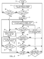
- FIG. 2 a flow diagram is shown that illustrates a method for controlling the application of regenerative braking torque generated by the generator 14 and the motor 50.
- the torque generated by the generator 14 and/or the motor 50 provides motive force to the vehicle.
- block 70 is the entry point for the method.
- the method includes applying regenerative braking torque at a desired level.
- the generator and/or motor of the vehicle are capable of providing regenerative braking torque.
- Block 72 depicts the determination of whether the ABS system has been engaged for the front wheels of the vehicle. If the ABS system has been activated, a timer is set as shown by block 73. It is recognized that in some instances it is possible for the front wheels of the vehicle to experience an ABS event, while the rear wheels do not experience an ABS event. As such, the time for which the timer is set may be dependent upon the vehicle wheel base and speed of the vehicle. In an alternative embodiment, the time for which the timer is set may be a predetermined time period, in a range of 45 seconds to one minute.
- the method reduces the regenerative braking torque applied to the rear wheels at a determined rate.
- Block 76 depicts the determination of whether the ABS system has been activated at the rear wheels. If the ABS system has not been activated, block 80 occurs.
- the method determines whether the vehicle has received an acceleration command via the vehicle's accelerator pedal. If the vehicle has not received an acceleration command, block 82 occurs.
- the method determines whether the vehicle has stopped. If the vehicle has not stopped, step 84 occurs and it is determined whether the timer originally set at block 73, has expired. If the timer has expired, the method determines whether the regenerative braking torque is at a desired level as shown by block 86. If the regenerative braking torque is not at a desired level, block 78 occurs.
- the regenerative braking torque is increased at a determined rate.
- the increase in regenerative braking torque occurs in a manner that is minimally noticeable, if not completely unnoticeable by vehicle occupants. If the regenerative braking torque is at a desired level, the method returns to block 71.
- the method also returns to block 71.
- block 88 occurs.
- the method determines whether the ABS has been activated at the rear wheels. If the ABS system has not been activated at the rear wheels, the method returns to block 71. In the event the ABS has been activated at the rear wheels, block 90 occurs.
- the method reduces the regenerative braking torque applied to the rear wheels for ABS control. Additionally, referring to block 76, if the ABS is active at the rear wheels, the method also reduces the regenerative braking on the rear wheels for ABS control.
- Block 92 depicts the performance of ABS control on the rear wheels. As shown by block 94, it is determined whether the ABS event is over. If the ABS event has not ended, the method returns to block 92. If the ABS event has ended, the method returns to block 80.
- the regenerative braking torque may be increased without waiting for the timer to expire in the event the rear wheels have experienced an ABS event that has ended (as determined at block 94).
Landscapes
- Engineering & Computer Science (AREA)
- Transportation (AREA)
- Mechanical Engineering (AREA)
- Power Engineering (AREA)
- Combustion & Propulsion (AREA)
- Chemical & Material Sciences (AREA)
- Life Sciences & Earth Sciences (AREA)
- Sustainable Development (AREA)
- Sustainable Energy (AREA)
- Automation & Control Theory (AREA)
- Electromagnetism (AREA)
- Physics & Mathematics (AREA)
- Electric Propulsion And Braking For Vehicles (AREA)
- Regulating Braking Force (AREA)
Abstract
Description
- The present invention relates to a method for operating a hybrid electric vehicle and in particular to a method for controlling regenerative braking of the hybrid electric vehicle.
- Regenerative braking systems seek to recover the kinetic energy of a vehicle, which is normally dissipated as heat by conventional hydraulic friction braking systems. The recovery of the kinetic energy occurs during braking via an electric motor that operates as a generator to restore power to a battery or other energy storage device. As commonly known, vehicles equipped with regenerative braking systems may also have anti-lock braking systems (ABS) that improve vehicle control and stability in the event of wheel slip. However, when a wheel slip condition occurs, the anti-lock brake system customarily causes disengagement of the regenerative braking system. Consequently, the vehicle operator experiences a lunge forward feeling due to the instantaneous loss of braking torque and deceleration. This sudden loss of deceleration is undesirable to the vehicle operator.
- It is an object of the invention to provide an improved method for controlling a regenerative braking system.
- According to a first aspect of the invention there is provided a method of controlling a vehicle having multiple wheels and a regenerative braking system for applying a braking torque to at least one of the wheels characterised in that the method comprises applying a braking torque to one wheel, determining whether a second wheel is experiencing an anti-lock braking system (ABS) event and compensating at a determined rate the braking torque applied to the one wheel upon determining whether the second wheel is experiencing the ABS event.
- The method may further comprise determining whether the one wheel is experiencing an ABS event.
- The method may further comprise applying braking torque to the one wheel upon determining that the ABS event has ended.
- Compensating, at the determined rate, the braking torque applied to the one wheel may include reducing the braking torque applied to the one wheel.
- The one wheel may include at least one wheel of a set of rear wheels of the vehicle and the second wheel may include at least one wheel of a set of front wheels of the vehicle.
- The vehicle may be a hybrid-electric vehicle having at least one electric machine and the method may further comprise applying regenerative braking torque to the rear wheels, determining whether the front wheels are experiencing an anti-lock braking system (ABS) event, through the use of an anti-lock braking system and compensating, at a determined rate, the regenerative braking torque being applied to the rear wheels upon determining that the front wheels are experiencing the ABS event, the regenerative braking torque being generated by the at least one electric machine.
- The at least one electric machine may be at least one of an electric motor and an electric generator.
- Compensating, at the determined rate, the regenerative braking torque being applied to the rear wheels may include reducing the braking torque applied to the rear wheels.
- The method may further comprise determining whether the rear wheels are experiencing an ABS event and compensating the regenerative braking torque applied to the rear wheels upon determining whether the rear wheels are experiencing the ABS event.
- Compensating the braking torque applied to the rear wheels may include substantially reducing the regenerative braking torque being applied to the rear wheels.
- The method may further comprise applying regenerative braking torque to the rear wheels upon determining that the ABS event has ended.
- The regenerative braking torque applied to the rear wheels may be applied subsequent to the expiration of a timer.
- According to a second aspect of the invention there is provided a vehicle having multiple wheels and a regenerative braking system for applying a braking torque to at least one of the wheels characterised in that the vehicle is configured to apply a braking torque to one wheel, determine whether at least a second wheel is experiencing an anti-lock braking system (ABS) event and, at a determined rate, compensate the regenerative braking torque applied to the one wheel upon determining that the second wheel is experiencing the ABS event.
- The vehicle may be further configured to determine whether the one wheel is experiencing an ABS event and is further configured to enable the application of regenerative braking torque to the one wheel upon determining that the ABS event has ended.
- The vehicle may be configured to compensate, at the determined rate, the regenerative braking torque applied to the one wheel by reducing the regenerative braking torque applied to the one wheel.
- Determining whether the second wheel is experiencing an ABS event may include determining whether an anti-lock braking (ABS) event has occurred.
- The one wheel may be at least one of a set of rear vehicle wheels.
- The second wheel may be at least one of a set of front vehicle wheels.
- The invention will now be described by way of example with reference to the accompanying drawing of which:-
- Figure 1 illustrates a vehicle having a regenerative braking system according to an embodiment of the present invention; and
- Figure 2 illustrates a flow diagram for a method for controlling a regenerative braking system in accordance with an embodiment of the present invention.
- By way of example, a system and method for implementing the present invention is described below. The system and methodology may be adapted, modified or rearranged to best fit a particular implementation without departing from the scope of the present invention.
- Figure 1 illustrates a schematic representation of a
vehicle 10 in accordance with one embodiment of the present invention. Thevehicle 10 includes anengine 12 and an electric machine, such asgenerator 14. Theengine 12 and thegenerator 14 are connected through a power transfer unit, which in this embodiment is aplanetary gear set 16. Of course, other types of power transfer units, including other gear sets and transmissions, may be used to connect theengine 12 to thegenerator 14. The planetary gear set includes aring gear 18, acarrier 20,planet gears 22, and asun gear 24. - The
generator 14 can also be used as a motor, outputting torque to ashaft 26 connected to thesun gear 24. Similarly, theengine 12 outputs torque to ashaft 28 connected to thecarrier 20. - A
brake 30 is in this case provided for stopping rotation of theshaft 26, thereby locking thesun gear 24 in place. Because this configuration allows torque to be transferred from thegenerator 14 to theengine 12, a one-way clutch 32 may be provided so that theshaft 28 rotates in only one direction. Having thegenerator 14 operatively connected to theengine 12, as shown in Figure 1, allows the speed of theengine 12 to be controlled by thegenerator 14. It will be appreciated that alternative embodiments may not include thebrake 30 and/or theclutch 32. - The
ring gear 18 is connected to ashaft 34, which is connected to rearvehicle drive wheels 36 through asecond gear set 38. Additionally, thevehicle 10 includes a set offront wheels 35 that may be directly coupled toengine 12. - The
vehicle 10 includes a second electric machine, ormotor 40, which can be used to output torque to ashaft 42. Other vehicles within the scope of the present invention may have different electric machine arrangements, such as more or less than two electric machines. - In the embodiment shown in Figure 1, the
motor 40 and thegenerator 14 can both be used as motors to output torque. Alternatively, each can also be used as a generator, outputting electrical power to ahigh voltage bus 44 and to an energy storage device, orbattery 46. - The
battery 46 is a high voltage battery that is capable of outputting electrical power to operate themotor 40 and thegenerator 14. Other types of energy storage devices and/or output devices can be used with a vehicle, such as thevehicle 10. For example, a device such as a capacitor can be used, which, like a high voltage battery, is capable of both storing and outputting electrical energy. Alternatively, a device such as a fuel cell may be used in conjunction with a battery and/or capacitor to provide electrical power for thevehicle 10. - As shown in Figure 1, the
motor 40, thegenerator 14, the planetary gear set 16, and a portion of thesecond gear set 38 may generally be referred to as atransaxle 48. Thetransaxle 48 is analogous to a transmission in a conventional vehicle. Thus, when a driver selects a particular gear, thetransaxle 48 is appropriately controlled to operate according to the gear selection. To control theengine 12 and the components of thetransaxle 48 such as thegenerator 14 andmotor 40, a control system, including afirst controller 50, is provided. - As shown in Figure 1, the
controller 50 is a combination vehicle system controller and powertrain control module (VSC/PCM). Although it is shown as a single hardware device, it may include multiple controllers in the form of multiple hardware devices, or multiple software controllers within one or more hardware devices. Thecontroller 50 logic, including logic associated with other controllers (e.g., TCM 56) may be partitioned in any number of ways without imposing any limitation on the claimed invention. - A controller area network (CAN) 52 allows the
controller 50 to communicate with thetransaxle 48 and a battery control module (BCM) 54. Just as thebattery 46 has theBCM 54, other devices controlled by thecontroller 50 may have their own controllers. For example, an engine control unit (ECU) may communicate with thecontroller 50 and may perform control functions on theengine 12. In addition, thetransaxle 48 may include one or more controllers, such as a transaxle control module (TCM)56, configured to control specific components within thetransaxle 48, such as thegenerator 14 and/or themotor 40. Accordingly, as shown in Figure 1, the TCM 56 communicates with agenerator inverter 45 and amotor inverter 41. In one embodiment, thegenerator inverter 45 and themotor inverter 41 are coupled to acontrol module 47 and acontrol module 43, respectively.Control modules TCM 56 and sending those readings to theTCM 56. - Although the
vehicle 10, shown in Figure 1, is a HEV, it is understood that the present invention can be used for of other types of vehicles. In addition, although thevehicle 10 shown in Figure 1 is a parallel-series HEV, the present invention is not limited to HEV's having such a "powersplit" configuration. Furthermore, although thevehicle 10 is illustrated having a single motor (i.e., motor 40), other embodiments may include additional motors without departing from the scope of the present invention. Thus, the present invention is applicable to an alternative embodiment ofvehicle 10 having a motor, such asmotor 40, coupled directly to a front axle (not shown) offront wheels 35. Additionally, in alternative embodiments thevehicle 10 may be a fuel-cell vehicle. - As shown,
vehicle 10 further includesfriction brakes 37.Brakes 37 include abrake disc 37a, acaliper 37b, and aspeed sensor 49 that communicates with an anti-lock braking system (ABS)module 39.Caliper 37b is operable withbrake disc 37a for slowing and/or stoppingvehicle 12.ABS module 39 is operable with apressure adjustment unit 51. In response to a brake request from abrake pedal 55,pressure adjustment unit 51 is configured to enable proper distribution of braking fluid pressure tobrakes 37 through the use ofliquid pressure passages 53. - Although the embodiment shown in Figure 1 illustrates a braking system that utilizes hydraulics, it is recognized that the friction braking system of Figure 1 may be a pure brake-by-wire (BBW) system, an electro-mechanical braking system, an electro-hydraulic braking system, or a hydromechanical braking system without departing from the scope of the present invention. In either embodiment,
ABS module 39 is operable withcontroller 50 andTCM 56 for monitoring and controlling the performance of thegenerator 14 and themotor 40. - In the
event wheels 35 enter ABS control viaABS module 39, during active regenerative braking, the torque generated by themotor 40 and/or thegenerator 14 is compensated. Compensation of the braking torque occurs in a manner so as to minimize or eliminate the loss of deceleration. The loss of deceleration may occur as a result of the operation of themotor 40, thegenerator 14 or an ABS event experienced bywheels 36 which causes the elimination of braking torque. - In one embodiment, the torque generated by the
motor 40 and thegenerator 14 is reduced in a controlled manner at a determined rate. Accordingly, the reduction in torque mitigates any "lunge forward" feeling experienced by vehicle occupants whenwheels 35 enter ABS mode and regenerative braking is reduced. - In one embodiment, the
ABS module 39 and thespeed sensor 49 detect a potentially locking wheel slip event experienced by thefront wheels 35. It is recognized that the term "wheel slip" herein refers to any condition which causes the engagement/activation of the ABS. - Upon detection of the wheel slip event (i.e., activation of ABS control) by
front wheels 35, theABS module 39 generates a signal for theTCM 56 that indicates the occurrence of ABS activation. As such, theTCM 56 is configured to generate signals for a controlled reduction of regenerative braking torque being applied torear wheels 36 by themotor 40 and thegenerator 14. Thus, when therear wheels 36 reach the road surface location where thefront wheels 35 experienced the wheel slip condition, the torque has been reduced in a manner that mitigates the "lunge forward" feeling that is caused by conventional regenerative braking systems. Consequently, when the ABS system is activated for therear wheels 36, any subsequent reduction in regenerative applied torque is less noticeable to the vehicle occupants. - In the event the ABS system is not activated within a determined time period for the
rear wheels 36, the amount of regenerative braking torque allowed at therear wheels 36 may be increased. Furthermore, in the event thevehicle 10 stops or begins accelerating, theTCM 56 generates signals for thegenerator 14 and themotor 50 to enable the application of an additional amount of torque to therear wheels 36. In one aspect of the present invention, the amount of added regenerative braking torque is equivalent to the original unreduced amount of regenerative braking torque. - Now, referring to Figure 2, a flow diagram is shown that illustrates a method for controlling the application of regenerative braking torque generated by the
generator 14 and themotor 50. As described above, the torque generated by thegenerator 14 and/or themotor 50 provides motive force to the vehicle. Accordingly, block 70 is the entry point for the method. - As depicted by
block 71, the method includes applying regenerative braking torque at a desired level. As described in the foregoing, the generator and/or motor of the vehicle are capable of providing regenerative braking torque. -
Block 72 depicts the determination of whether the ABS system has been engaged for the front wheels of the vehicle. If the ABS system has been activated, a timer is set as shown byblock 73. It is recognized that in some instances it is possible for the front wheels of the vehicle to experience an ABS event, while the rear wheels do not experience an ABS event. As such, the time for which the timer is set may be dependent upon the vehicle wheel base and speed of the vehicle. In an alternative embodiment, the time for which the timer is set may be a predetermined time period, in a range of 45 seconds to one minute. - As shown by
block 74, the method reduces the regenerative braking torque applied to the rear wheels at a determined rate. -
Block 76 depicts the determination of whether the ABS system has been activated at the rear wheels. If the ABS system has not been activated, block 80 occurs. - At
block 80, the method determines whether the vehicle has received an acceleration command via the vehicle's accelerator pedal. If the vehicle has not received an acceleration command, block 82 occurs. - At
block 82, the method determines whether the vehicle has stopped. If the vehicle has not stopped,step 84 occurs and it is determined whether the timer originally set atblock 73, has expired. If the timer has expired, the method determines whether the regenerative braking torque is at a desired level as shown byblock 86. If the regenerative braking torque is not at a desired level, block 78 occurs. - At
block 78, the regenerative braking torque is increased at a determined rate. The increase in regenerative braking torque occurs in a manner that is minimally noticeable, if not completely unnoticeable by vehicle occupants. If the regenerative braking torque is at a desired level, the method returns to block 71. - Referring back to block 80, if the vehicle acceleration has been commanded, the method returns to block 71.
- Referring to block 82, if the vehicle has stopped, the method also returns to block 71.
- Referring to block 84, if the timer has not expired, the method returns to block 74.
- Now, referring back to block 72, if the ABS system has not been activated at the front wheels, block 88 occurs. At
block 88, the method determines whether the ABS has been activated at the rear wheels. If the ABS system has not been activated at the rear wheels, the method returns to block 71. In the event the ABS has been activated at the rear wheels, block 90 occurs. - At
block 90, the method reduces the regenerative braking torque applied to the rear wheels for ABS control. Additionally, referring to block 76, if the ABS is active at the rear wheels, the method also reduces the regenerative braking on the rear wheels for ABS control. -
Block 92 depicts the performance of ABS control on the rear wheels. As shown byblock 94, it is determined whether the ABS event is over. If the ABS event has not ended, the method returns to block 92. If the ABS event has ended, the method returns to block 80. - In alternative embodiments, the regenerative braking torque may be increased without waiting for the timer to expire in the event the rear wheels have experienced an ABS event that has ended (as determined at block 94).
- It will be appreciated that in the case of a front drive vehicle the regenerative braking will be supplied to the front wheels and whether one or more of the rear wheels are experiencing an anti-lock braking system event will be determined and the braking torque applied to the front wheel will compensated at a determined rate upon determining whether the one or more rear wheel is experiencing the ABS event.
- It will be further appreciated by those skilled in the art that although the invention has been described by way of example with reference to one or more embodiments it is not limited to the disclosed embodiments and that one or more modifications to the disclosed embodiments or alternative embodiments could be constructed without departing from the scope of the invention.
Claims (10)
- A method of controlling a vehicle (10) having multiple wheels (35, 36) and a regenerative braking system for applying a braking torque to at least one of the wheels (36) characterised in that the method comprises applying a braking torque to one wheel (36), determining whether a second wheel (35) is experiencing an anti-lock braking system (ABS) event and compensating at a determined rate the braking torque applied to the one wheel (36) upon determining whether the second wheel (35) is experiencing the ABS event.
- A method as claimed in claim 1 wherein the method further comprises determining whether the one wheel (36) is experiencing an ABS event.
- A method as claimed in claim 2 wherein the method further comprises applying braking torque to the one wheel (36) upon determining that the ABS event has ended.
- A method as claimed in any of claims 1 to 3 wherein compensating, at the determined rate, the braking torque applied to the one wheel (36) includes reducing the braking torque applied to the one wheel (36).
- A method as claimed in any of claims 1 to 4 wherein the one wheel includes at least one wheel of a set of rear wheels (36) of the vehicle (10) and the second wheel includes at least one wheel of a set of front wheels (35) of the vehicle (10) .
- A method as claimed in claim 5 wherein the vehicle is a hybrid-electric vehicle (10) having at least one electric machine (14, 40) and the method further comprises applying regenerative braking torque to the rear wheels (36), determining whether the front wheels (35) are experiencing an anti-lock braking system (ABS) event, through the use of an anti-lock braking system and compensating, at a determined rate, the regenerative braking torque being applied to the rear wheels (36) upon determining that the front wheels (35) are experiencing the ABS event, the regenerative braking torque being generated by the at least one electric machine (14, 40).
- A method as claimed in claim 6 wherein the regenerative braking torque applied to the rear wheels (36) is applied subsequent to the expiration of a timer.
- A vehicle (10) having multiple wheels (35, 36) and a regenerative braking system for applying a braking torque to at least one of the wheels (36) characterised in that the vehicle (10) is configured to apply a braking torque to one wheel (36), determine whether at least a second wheel (35) is experiencing an anti-lock braking system (ABS) event and, at a determined rate, compensate the regenerative braking torque applied to the one wheel (36) upon determining that the second wheel (35) is experiencing the ABS event.
- A vehicle as claimed in claim 8 wherein the vehicle is further configured to determine whether the one wheel (36) is experiencing an ABS event and is further configured to enable the application of regenerative braking torque to the one wheel (36) upon determining that the ABS event has ended.
- A vehicle as claimed in claim 8 or in claim 9 wherein the vehicle (10) is configured to compensate, at the determined rate, the regenerative braking torque applied to the one wheel (36) by reducing the regenerative braking torque applied to the one wheel (36).
Applications Claiming Priority (1)
| Application Number | Priority Date | Filing Date | Title |
|---|---|---|---|
| US11/164,195 US20070108838A1 (en) | 2005-11-14 | 2005-11-14 | Regenerative braking control system and method |
Publications (2)
| Publication Number | Publication Date |
|---|---|
| EP1785309A2 true EP1785309A2 (en) | 2007-05-16 |
| EP1785309A3 EP1785309A3 (en) | 2008-10-15 |
Family
ID=37806830
Family Applications (1)
| Application Number | Title | Priority Date | Filing Date |
|---|---|---|---|
| EP06123158A Withdrawn EP1785309A3 (en) | 2005-11-14 | 2006-10-30 | A method of controlling a vehicle having a regenerative braking system |
Country Status (4)
| Country | Link |
|---|---|
| US (1) | US20070108838A1 (en) |
| EP (1) | EP1785309A3 (en) |
| JP (1) | JP5030532B2 (en) |
| CN (1) | CN1966302B (en) |
Cited By (6)
| Publication number | Priority date | Publication date | Assignee | Title |
|---|---|---|---|---|
| WO2009144064A1 (en) * | 2008-05-26 | 2009-12-03 | Robert Bosch Gmbh | Method for regulating a drag torque of a motor vehicle driven by an electric motor in consideration of the friction coefficient present on the roadway surface, and device for carrying out such a method |
| CN101905659A (en) * | 2009-06-06 | 2010-12-08 | 福特全球技术公司 | Regenerative brake control system and method |
| CN102774366A (en) * | 2012-07-23 | 2012-11-14 | 广州市科密汽车制动技术开发有限公司 | Integrated ABS (anti-lock brake system) vehicle brake energy recovery system and method |
| TWI399307B (en) * | 2009-11-13 | 2013-06-21 | Ind Tech Res Inst | A driving method for an electric vehicle with anti-skid function and apparatus thereof |
| CN104635667A (en) * | 2014-12-07 | 2015-05-20 | 北京工业大学 | Electric vehicle regenerative braking and ESP coordinated control quick development platform |
| CN104924914A (en) * | 2015-06-15 | 2015-09-23 | 中通客车控股股份有限公司 | Electric automobile braking system and braking control method |
Families Citing this family (36)
| Publication number | Priority date | Publication date | Assignee | Title |
|---|---|---|---|---|
| US7395887B2 (en) * | 2004-12-23 | 2008-07-08 | Bosch Rexroth Corporation | Complementary regenerative torque system and method of controlling same |
| US7654620B2 (en) * | 2006-10-26 | 2010-02-02 | Hyundai Motor Company | Method for control regenerative braking of electric vehicle |
| US20120207620A1 (en) | 2007-07-12 | 2012-08-16 | Odyne Systems, LLC. | Hybrid vehicle drive system and method and idle reduction system and method |
| US8978798B2 (en) | 2007-10-12 | 2015-03-17 | Odyne Systems, Llc | Hybrid vehicle drive system and method and idle reduction system and method |
| US8408341B2 (en) | 2007-07-12 | 2013-04-02 | Odyne Systems, Llc | Hybrid vehicle drive system and method and idle reduction system and method |
| US9061680B2 (en) | 2007-07-12 | 2015-06-23 | Odyne Systems, Llc | Hybrid vehicle drive system and method for fuel reduction during idle |
| WO2013081657A1 (en) | 2011-12-02 | 2013-06-06 | Odyne Systems, Llc | System for and method of fuel optimization in a hybrid vehicle |
| JP2010075036A (en) * | 2008-08-22 | 2010-04-02 | Fuji Heavy Ind Ltd | Controlling apparatus of electric automobile |
| JP5302749B2 (en) * | 2009-04-20 | 2013-10-02 | 富士重工業株式会社 | Electric vehicle control device |
| CN102029915B (en) * | 2009-09-25 | 2013-06-26 | 株式会社万都 | Regenerative braking system |
| US8788144B2 (en) * | 2009-11-30 | 2014-07-22 | GM Global Technology Operations LLC | Braking torque adjustments based on wheel slip |
| US8645040B2 (en) * | 2010-05-06 | 2014-02-04 | GM Global Technology Operations LLC | Method for operating a vehicle brake system |
| EP2615004B1 (en) * | 2010-09-09 | 2017-12-06 | Bosch Corporation | Vehicle brake device and method of controlling vehicle brake device |
| KR101259361B1 (en) * | 2011-04-18 | 2013-04-30 | 주식회사 만도 | Vehicles braking system and method of controlling the same |
| FR2982205B1 (en) * | 2011-11-08 | 2014-04-11 | Renault Sa | ADAPTING A SIMULATED ENGINE BRAKE SET |
| US11225240B2 (en) | 2011-12-02 | 2022-01-18 | Power Technology Holdings, Llc | Hybrid vehicle drive system and method for fuel reduction during idle |
| US12330657B2 (en) | 2011-12-02 | 2025-06-17 | Power Technology Holdings Llc | Hybrid vehicle drive system and method for fuel reduction during idle |
| US9878621B2 (en) * | 2012-12-08 | 2018-01-30 | Ford Global Technologies, Llc | System and method for improved ABS performance during parallel regenerative braking |
| US10358037B2 (en) * | 2013-03-28 | 2019-07-23 | Honda Motor Co., Ltd. | Vehicular brake system |
| US9586488B2 (en) * | 2013-05-21 | 2017-03-07 | Toyota Jidosha Kabushiki Kaisha | Brake apparatus |
| KR101519227B1 (en) * | 2013-10-18 | 2015-05-11 | 현대자동차주식회사 | Controlling method and system for operating Anti-lock Brake System of vehicle |
| WO2015074074A1 (en) | 2013-11-18 | 2015-05-21 | Odyne Systems, Llc | Hybrid vehicle drive system and method using split shaft power take off |
| US11027613B2 (en) * | 2014-02-03 | 2021-06-08 | Ford Global Technologies, Llc | Regenerative braking control system and method |
| CN104108316B (en) * | 2014-04-12 | 2017-01-25 | 北京工业大学 | Electrohydraulic-combined brake control method of battery electric vehicle |
| CN106604841A (en) * | 2014-08-22 | 2017-04-26 | 博格华纳公司 | Multimode clutch for through-the-road hybrid vehicle |
| US9637004B2 (en) * | 2015-06-18 | 2017-05-02 | E-Aam Driveline Systems Ab | System and method for delimiting regenerative braking |
| CN105523029B (en) * | 2015-12-29 | 2018-04-06 | 北京新能源汽车股份有限公司 | Electric automobile and brake control method and system thereof |
| CN108859763A (en) * | 2017-05-09 | 2018-11-23 | 郑州宇通客车股份有限公司 | A kind of control method and device preventing new-energy automobile sliding, braking shake |
| US10399440B2 (en) | 2017-06-15 | 2019-09-03 | Ford Global Technologies, Llc | Methods and system for regenerative hybrid vehicle braking |
| WO2019074581A1 (en) | 2017-10-11 | 2019-04-18 | Cummins Inc. | Torque deration in response traction control events |
| CN109808502B (en) * | 2017-11-22 | 2022-02-08 | 比亚迪股份有限公司 | An energy feedback exit control method suitable for pure electric vehicles |
| KR102882420B1 (en) * | 2019-12-16 | 2025-11-06 | 현대자동차주식회사 | Apparatus for controlling regenerative braking torque of electric vehicle and method thereof |
| US11932138B2 (en) * | 2020-10-28 | 2024-03-19 | Nissan Motor Co., Ltd. | Electric vehicle control method and electric vehicle control system |
| CN113978466B (en) * | 2021-10-25 | 2024-04-05 | 智新控制系统有限公司 | Anti-skid control method and system for electric automobile driving system |
| GB2617099B (en) * | 2022-03-29 | 2024-08-07 | Jaguar Land Rover Ltd | Controlling thermal energy from vehicle regenerative braking |
| FR3143462B1 (en) * | 2022-12-14 | 2025-04-11 | Phoenix Mobility | CONVERSION KIT FOR TRANSFORMING A THERMAL VEHICLE INTO AN ELECTRIC VEHICLE, CONVERTED VEHICLE AND RELATED METHOD |
Family Cites Families (14)
| Publication number | Priority date | Publication date | Assignee | Title |
|---|---|---|---|---|
| US5472265A (en) * | 1992-12-10 | 1995-12-05 | Toyota Jidosha Kabushiki Kaisha | Antilock braking control apparatus for electric vehicle |
| JP3438242B2 (en) * | 1992-12-10 | 2003-08-18 | トヨタ自動車株式会社 | Electric vehicle anti-lock control device |
| US6179395B1 (en) * | 1997-10-01 | 2001-01-30 | Visteon Global Technologies, Inc. | Method and apparatus for regenerative and anti-skid friction braking |
| US6099089A (en) * | 1997-11-01 | 2000-08-08 | Ford Motor Company | Method and apparatus for regenerative and friction braking |
| US6709075B1 (en) * | 2000-08-07 | 2004-03-23 | Ford Global Technologies, Llc | System and method for braking an electric drive vehicle on a low Mu surface |
| US6378636B1 (en) * | 2000-10-11 | 2002-04-30 | Ford Global Technologies, Inc. | Method and system for providing for vehicle drivability feel after accelerator release in an electric or hybrid electric vehicle |
| US6488344B2 (en) * | 2001-05-03 | 2002-12-03 | Ford Motor Company | Distribution of torque when driven wheels slip during regenerative braking |
| JP3811372B2 (en) * | 2001-05-30 | 2006-08-16 | トヨタ自動車株式会社 | Braking force control device for vehicle |
| JP4058932B2 (en) * | 2001-10-25 | 2008-03-12 | トヨタ自動車株式会社 | Brake control device for vehicle |
| DE10204723A1 (en) * | 2002-02-05 | 2003-08-14 | Continental Teves Ag & Co Ohg | Procedure for coordinating the use of a regenerative and an anti-lock system |
| JP3921109B2 (en) * | 2002-03-20 | 2007-05-30 | 日産ディーゼル工業株式会社 | Vehicle hybrid system |
| US6719379B2 (en) * | 2002-06-20 | 2004-04-13 | Ford Motor Company | Method and an apparatus for braking a vehicle |
| US6687593B1 (en) * | 2002-09-06 | 2004-02-03 | Ford Motor Company | Combined regenerative and friction braking system for a vehicle |
| US7441845B2 (en) * | 2004-09-13 | 2008-10-28 | Ford Global Technologies, Llc | Method for operating multiple axle regenerative braking in an automotive vehicle |
-
2005
- 2005-11-14 US US11/164,195 patent/US20070108838A1/en not_active Abandoned
-
2006
- 2006-10-30 EP EP06123158A patent/EP1785309A3/en not_active Withdrawn
- 2006-10-31 JP JP2006296572A patent/JP5030532B2/en not_active Expired - Fee Related
- 2006-11-14 CN CN2006101381453A patent/CN1966302B/en not_active Expired - Fee Related
Cited By (9)
| Publication number | Priority date | Publication date | Assignee | Title |
|---|---|---|---|---|
| WO2009144064A1 (en) * | 2008-05-26 | 2009-12-03 | Robert Bosch Gmbh | Method for regulating a drag torque of a motor vehicle driven by an electric motor in consideration of the friction coefficient present on the roadway surface, and device for carrying out such a method |
| CN101905659A (en) * | 2009-06-06 | 2010-12-08 | 福特全球技术公司 | Regenerative brake control system and method |
| CN101905659B (en) * | 2009-06-06 | 2014-02-19 | 福特全球技术公司 | Regenerative brake control system and method |
| TWI399307B (en) * | 2009-11-13 | 2013-06-21 | Ind Tech Res Inst | A driving method for an electric vehicle with anti-skid function and apparatus thereof |
| CN102774366A (en) * | 2012-07-23 | 2012-11-14 | 广州市科密汽车制动技术开发有限公司 | Integrated ABS (anti-lock brake system) vehicle brake energy recovery system and method |
| CN102774366B (en) * | 2012-07-23 | 2014-12-24 | 广州科密汽车电子控制技术股份有限公司 | Integrated ABS (anti-lock brake system) vehicle brake energy recovery system and method |
| CN104635667A (en) * | 2014-12-07 | 2015-05-20 | 北京工业大学 | Electric vehicle regenerative braking and ESP coordinated control quick development platform |
| CN104635667B (en) * | 2014-12-07 | 2017-05-24 | 北京工业大学 | Electric vehicle regenerative braking and ESP coordinated control quick development platform |
| CN104924914A (en) * | 2015-06-15 | 2015-09-23 | 中通客车控股股份有限公司 | Electric automobile braking system and braking control method |
Also Published As
| Publication number | Publication date |
|---|---|
| CN1966302B (en) | 2012-10-10 |
| CN1966302A (en) | 2007-05-23 |
| JP2007137413A (en) | 2007-06-07 |
| EP1785309A3 (en) | 2008-10-15 |
| US20070108838A1 (en) | 2007-05-17 |
| JP5030532B2 (en) | 2012-09-19 |
Similar Documents
| Publication | Publication Date | Title |
|---|---|---|
| EP1785309A2 (en) | A method of controlling a vehicle having a regenerative braking system | |
| JP4901151B2 (en) | Active motor damping method to reduce drivetrain vibration of electric vehicles | |
| EP2330007B1 (en) | Vehicle braking | |
| JP4601920B2 (en) | Vehicle braking device | |
| JP5351256B2 (en) | Brake device for automobile, operation method thereof and hydraulic device | |
| US20080100129A1 (en) | Vehicle System Having Regenerative Brake Control | |
| JP2003018701A (en) | Torque distribution method at slip of drive wheel during regenerative braking | |
| KR20140069280A (en) | Slip-controlled braking system for electrically driven motor vehicles | |
| WO2015068800A1 (en) | Braking force control system | |
| CN105437983B (en) | Vehicle system and method for adjusting lift pedal regeneration | |
| JP4998036B2 (en) | Vehicle control device | |
| US12172641B2 (en) | Electrified vehicle configured to selectively increase energy recovery threshold and corresponding method | |
| EP1348592B1 (en) | A method and apparatus for vehicle regenerative braking | |
| GB2455507A (en) | Electric motor vehicle emergency braking system | |
| CN102442310A (en) | Method and driveline stability control system for a vehicle | |
| US7410023B2 (en) | System and method for braking a vehicle | |
| US20250304070A1 (en) | Method, Device, Controller, and Computer Program Product for Comfortable Braking | |
| US20080090696A1 (en) | System and method for controlling a vehicle | |
| JP7842885B2 (en) | Method and brake system for controlling a hydraulic brake system | |
| JP2013158200A (en) | Passive torque split four-wheel-drive vehicle | |
| US12005885B2 (en) | System comprising a control device for a utility vehicle, as well as a method for operating a utility vehicle with the system | |
| JP7636591B2 (en) | Brake control device for a vehicle and method for operating a brake control device for a vehicle | |
| JP2020069817A (en) | Braking force control device | |
| EP3932723A1 (en) | Improved braking system for an automatic driving vehicle | |
| JP2025171458A (en) | Vehicle drive unit |
Legal Events
| Date | Code | Title | Description |
|---|---|---|---|
| PUAI | Public reference made under article 153(3) epc to a published international application that has entered the european phase |
Free format text: ORIGINAL CODE: 0009012 |
|
| AK | Designated contracting states |
Kind code of ref document: A2 Designated state(s): AT BE BG CH CY CZ DE DK EE ES FI FR GB GR HU IE IS IT LI LT LU LV MC NL PL PT RO SE SI SK TR |
|
| AX | Request for extension of the european patent |
Extension state: AL BA HR MK YU |
|
| PUAL | Search report despatched |
Free format text: ORIGINAL CODE: 0009013 |
|
| AK | Designated contracting states |
Kind code of ref document: A3 Designated state(s): AT BE BG CH CY CZ DE DK EE ES FI FR GB GR HU IE IS IT LI LT LU LV MC NL PL PT RO SE SI SK TR |
|
| AX | Request for extension of the european patent |
Extension state: AL BA HR MK RS |
|
| RIC1 | Information provided on ipc code assigned before grant |
Ipc: B60T 8/00 20060101ALI20080905BHEP Ipc: B60L 7/00 20060101AFI20070313BHEP |
|
| 17P | Request for examination filed |
Effective date: 20090318 |
|
| 17Q | First examination report despatched |
Effective date: 20090529 |
|
| AKX | Designation fees paid |
Designated state(s): DE FR GB |
|
| STAA | Information on the status of an ep patent application or granted ep patent |
Free format text: STATUS: THE APPLICATION IS DEEMED TO BE WITHDRAWN |
|
| 18D | Application deemed to be withdrawn |
Effective date: 20091009 |
|
| P01 | Opt-out of the competence of the unified patent court (upc) registered |
Effective date: 20230620 |