EP1785226A2 - Adjusting device - Google Patents
Adjusting device Download PDFInfo
- Publication number
- EP1785226A2 EP1785226A2 EP06023277A EP06023277A EP1785226A2 EP 1785226 A2 EP1785226 A2 EP 1785226A2 EP 06023277 A EP06023277 A EP 06023277A EP 06023277 A EP06023277 A EP 06023277A EP 1785226 A2 EP1785226 A2 EP 1785226A2
- Authority
- EP
- European Patent Office
- Prior art keywords
- adjusting
- respect
- handwheel
- pin
- slide
- Prior art date
- Legal status (The legal status is an assumption and is not a legal conclusion. Google has not performed a legal analysis and makes no representation as to the accuracy of the status listed.)
- Granted
Links
- 238000009966 trimming Methods 0.000 claims description 48
- 230000035515 penetration Effects 0.000 claims description 4
- 241000826860 Trapezium Species 0.000 claims 2
- 239000000463 material Substances 0.000 description 7
- 238000003754 machining Methods 0.000 description 4
- 239000002023 wood Substances 0.000 description 3
- 230000006866 deterioration Effects 0.000 description 2
- 230000002427 irreversible effect Effects 0.000 description 1
- 230000036316 preload Effects 0.000 description 1
- 230000001737 promoting effect Effects 0.000 description 1
- 230000001131 transforming effect Effects 0.000 description 1
- 230000002747 voluntary effect Effects 0.000 description 1
Images


Classifications
-
- B—PERFORMING OPERATIONS; TRANSPORTING
- B23—MACHINE TOOLS; METAL-WORKING NOT OTHERWISE PROVIDED FOR
- B23Q—DETAILS, COMPONENTS, OR ACCESSORIES FOR MACHINE TOOLS, e.g. ARRANGEMENTS FOR COPYING OR CONTROLLING; MACHINE TOOLS IN GENERAL CHARACTERISED BY THE CONSTRUCTION OF PARTICULAR DETAILS OR COMPONENTS; COMBINATIONS OR ASSOCIATIONS OF METAL-WORKING MACHINES, NOT DIRECTED TO A PARTICULAR RESULT
- B23Q5/00—Driving or feeding mechanisms; Control arrangements therefor
- B23Q5/22—Feeding members carrying tools or work
- B23Q5/34—Feeding other members supporting tools or work, e.g. saddles, tool-slides, through mechanical transmission
- B23Q5/341—Feeding other members supporting tools or work, e.g. saddles, tool-slides, through mechanical transmission cam-operated
-
- B—PERFORMING OPERATIONS; TRANSPORTING
- B23—MACHINE TOOLS; METAL-WORKING NOT OTHERWISE PROVIDED FOR
- B23Q—DETAILS, COMPONENTS, OR ACCESSORIES FOR MACHINE TOOLS, e.g. ARRANGEMENTS FOR COPYING OR CONTROLLING; MACHINE TOOLS IN GENERAL CHARACTERISED BY THE CONSTRUCTION OF PARTICULAR DETAILS OR COMPONENTS; COMBINATIONS OR ASSOCIATIONS OF METAL-WORKING MACHINES, NOT DIRECTED TO A PARTICULAR RESULT
- B23Q16/00—Equipment for precise positioning of tool or work into particular locations not otherwise provided for
- B23Q16/02—Indexing equipment
- B23Q16/022—Indexing equipment in which only the indexing movement is of importance
- B23Q16/024—Indexing equipment in which only the indexing movement is of importance and by converting a continuous movement into a linear indexing movement
Definitions
- the invention relates to an adjusting device arranged for adjusting a corresponding vertical position of a first element with respect to a second element, the first element being vertically movable with respect to the second element.
- the invention relates to an adjusting device arranged for adjusting in an initial adjusting step a mutual vertical position of copiers and respective trimming tools that are associable with trimming machines designed for trimming an edge previously applied to a workpiece made of wood or similar materials.
- the copiers an upper one and a lower one, are elements that are movable vertically along an axis Z and are arranged for respectively tracing an upper and lower profile of a workpiece to be trimmed, for example a shaped panel.
- the copiers are mounted on a vertically movable, support to which the trimming tool is fixed, for example comprising routing cutters provided with shaped plates.
- the copiers are kept constantly in contact, through elastic means, with the aforesaid workpiece, so as to detect an altimetric profile thereof.
- the copiers set a work height for the trimming tool 6 in function of the altimetric profile detected instant by instant.
- Adjusting devices are known that are associable with copiers of trimming machines, arranged, in an initial adjusting step, for adjusting a position, along the aforesaid axis Z, of the copiers with respect to the corresponding trimming tool, in such a way that the latter removes from the edge of the workpiece a desired quantity of material.
- the adjusting devices for example enable a pass depth of the trimming tool to be adjusted to remove a desired quantity of material from the edge and/or wear to the plates of the trimming tool to be compensated for. Adjusting devices are known that adjust the position of the copiers with respect to the trimming tools through a comparator.
- the copiers are locked in a desired position by means of a dedicated tool.
- a drawback of such devices is that the aforesaid operations make adjusting excessively slow, with consequent increase in tooling time, and sometimes not very precise, with consequent deterioration of machining quality.
- a further drawback is the need to provide highly qualified staff to perform such operations in order to limit the aforesaid imprecisions.
- a drawback of the aforesaid adjusting devices relates to the impossibility of performing very precise micrometric adjustments due to the existing play between the threads of the screw and of the nut, with consequent imprecision in execution and deterioration of machining quality.
- a further drawback is that such devices require tools for tightening and/or loosening the screw with consequent greater expense.
- An object of the invention is to improve the adjusting devices arranged for adjusting a mutual vertical position of copiers and respective trimming tools associable with trimming machines designed for trimming a previously applied edge on a workpiece made of wood or similar materials.
- a further object is to make adjusting devices that enable rapid adjustment, thereby reducing tooling time.
- a still further object is to obtain adjusting devices that enable very accurate micrometric adjustments to be made.
- Still another object is to devise adjusting devices that for being used do not require highly qualified staff.
- an adjusting device is arranged for adjusting a position, with respect to an adjusting axis, of a first element with respect to a second element, said first element being supported by slide means movable along said adjusting axis with respect to said second element, characterised in that said device comprises handwheel means that is rotatable with respect to said slide means; said handwheel means comprising shaped groove means rotationally engaging with pin means fixed along said adjusting axis with respect to said second element.
- said first element comprises copiers of a trimming machine and said second element comprises trimming tools.
- said adjusting device comprises antirotation pin means, fixed to said handwheel means, said antirotation pin means being slidable along said adjusting axis in guide means and being arranged for transforming a rotation of said shaped groove means with respect to said pin means into a rectilinear movement along said adjusting axis of said slide means.
- an adjusting device of a trimming machine of edged panels comprising adjusting means arranged for adjusting a position, with respect to an adjusting axis, of a copier with respect to a finishing tool, characterised in that said adjusting means comprises continuous adjusting means.
- the handwheel means is provided with a graduated scale that can be read simply and immediately and it is sufficient to rotate the handwheel means to obtain the desired adjustment.
- FIG. 1 With reference to Figure 1, there are shown operating heads 2 of a trimming machine 1 arranged for trimming an edge previously applied to a panel made of wood or similar material, which is not shown.
- the mutually facing operating heads 2 are arranged for machining an upper surface and a lower surface of the edge of the panel.
- the operating heads 2 are fixed to plates 4 that are vertically movable along tube elements 8.
- the operating heads 2 comprise a spindle 5 arranged for supporting during rotation a trimming tool 6, for example a routing cutter provided with shaped plates 7.
- the adjusting device 10 is arranged for adjusting, in an initial adjusting step, a work position, with respect to a substantially vertical adjusting axis Z of copiers 11, with which the trimming machine 1 is provided, and respective trimming tools 6.
- the adjusting device 10 enables a pass depth of the trimming tool 6 to be adjusted in such a way that the latter removes a desired quantity of material from the edge of the panel and/or wear to the plates 7 of the trimming tool 6 to be compensated for.
- the copiers 11 are fixed, through a threaded connection, to a substantially trapezoid copier-holder support 20.
- the copier-holder support 20 is associated, for example through a screw 21, with a slide 22.
- the slide 22 with a substantially parallelpipedon shape with a rectangular base extends in use along a direction that is substantially parallel to the aforesaid adjusting axis Z and is provided with a through hole 50.
- the adjusting device 10 further comprises an antirotation pin 23 engaging in the through hole 50, for example through interference.
- the antirotation pin 23 extending in a transverse direction to the aforesaid adjusting axis Z comprises a first end 24 and a second end 25.
- the first end 24 is provided with an internally threaded hole 26 whilst the second end 25 comprises an externally threaded portion 27.
- the first end 24 is arranged for rotationally supporting a handwheel 12 having a substantially disc shape, between the antirotation pin 23 and the handwheel 12 there being interposed a bush 28.
- the handwheel 12 is provided with a knurled side surface 54 in such a way as to facilitate the handling thereof, and comprises a mutually opposite first face 13 and second face 14.
- the first face 13 comprises an annular surface 15 and a circular surface 16 that are concentric and positioned on parallel planes.
- a substantially cylindrical cavity 18 is defined.
- the annular surface 15 is arranged for receiving a graduated scale element 17, whilst the cavity 18 is arranged for receiving, at least partially, a substantially disc-shaped locking element 19.
- the locking element 19, provided with a reference incision 55, is fixed by means of a further screw 30 to the first end 24 of the pin 23.
- the handwheel 12 is interposed between the locking element 19 and the copier-holder support 20.
- the locking element 19 is further provided with an arresting screw 31, having a surface 32 arranged for interacting with a portion of the circular surface 16.
- the second face 14 of the handwheel 12 comprises a groove 35 ( Figures 6 and 7), spirally shaped, having a trapezoid profile section ( Figure 2).
- the second end 25 of the antirotation pin 23 is arranged for passing through a further hole 51 of a support 37, that is fixed to the collar 9.
- the support 37 is provided with a slot 36 that is substantially concentric on the aforesaid further hole 51.
- the second end 25 is coupled, through a threaded connection, to a nut 38, opposite the further screw 30, and is arranged for sliding along a direction substantially parallel to the adjusting axis Z in the slot 36, between the nut 38 and the slot 36 there being interposed washer means 50'.
- the slide 22 is interposed between the support 37 and the handwheel 12.
- the support 37 is further provided with another hole 60 arranged for engaging with a wedge 40 with which the adjusting device 10 is provided.
- the wedge 40 comprises an externally threaded side surface 41 and a substantially conical tip 42 arranged for engaging with the groove 35 in such a way as to support the handwheel 12 rotatingly in use.
- the wedge 40 is associated with the support 37 through a further nut 52 and an adjusting bush 43, between the further nut 42 and the adjusting bush 43 there being interposed a washer 44.
- the adjusting device 10 is used in an initial adjusting step, before the trimming machine 1 performs trimming of the edge of the panel, to adjust the corresponding position along the adjusting axis Z between the copiers 11 and the trimming tools 6 in such a way as to determine a desired pass depth of the latter with respect to the edge of the panel.
- the adjusting device 10 Due to a rotation of the handwheel 12 with respect to the wedge 40, the antirotation pin 23 moves in the slot 36 along a direction substantially parallel to the adjusting axis Z, dragging with it the slide 22 and consequently the copiers 11.
- the graduated scale 17 of the handwheel 12 is, with respect to the reference incision 55, in a position indicated by the number "0".
- the copiers 11 are consequently moved in the direction indicated by the further arrow T2 moving them away, with respect to the adjusting axis Z, from the trimming tools 6, increasing a distance D ( Figure 2) between the copiers 11 and the respective tools 6, measured along a direction parallel to the adjusting axis Z.
- the arresting screw 31 is used to lock the handwheel 12 in this position.
- arresting screw 31 acts as a safety element, inasmuch as the adjusting device 10 is irreversible, and thus prevents rectilinear movements of the copiers 11 that are not generated by the voluntary rotation of the handwheel 12, such as for example accidental blows.
- the copiers 11 are consequently moved in the direction indicated by the further other arrow T1, moving them, with respect to the adjusting axis Z, towards the trimming tools 6, reducing the distance D.
- the arresting screw 31 is used for locking the handwheel 12 in this position.
- an adjusting device provided with a variable "0".
- the copiers 11 are vertically movable along an axis W, substantially parallel to the adjusting axis Z, fixed relative to the operating heads 2 and are arranged for tracing respectively an upper edge zone and a lower edge zone of the shaped panel in such a way as to detect the altimetric profile thereof.
- the copiers 11 set a work height for the trimming tool 6 in function of the altimetric profile detected instant by instant.
Landscapes
- Engineering & Computer Science (AREA)
- Mechanical Engineering (AREA)
- Machine Tool Copy Controls (AREA)
- Non-Portable Lighting Devices Or Systems Thereof (AREA)
Abstract
Description
- The invention relates to an adjusting device arranged for adjusting a corresponding vertical position of a first element with respect to a second element, the first element being vertically movable with respect to the second element. In particular, the invention relates to an adjusting device arranged for adjusting in an initial adjusting step a mutual vertical position of copiers and respective trimming tools that are associable with trimming machines designed for trimming an edge previously applied to a workpiece made of wood or similar materials.
- The copiers, an upper one and a lower one, are elements that are movable vertically along an axis Z and are arranged for respectively tracing an upper and lower profile of a workpiece to be trimmed, for example a shaped panel.
- The copiers are mounted on a vertically movable, support to which the trimming tool is fixed, for example comprising routing cutters provided with shaped plates.
- In this way, in use, to a vertical movement of the copiers and thus of the support, there corresponds a vertical movement of equal amount of the trimming tool.
- In particular, during operation, the copiers are kept constantly in contact, through elastic means, with the aforesaid workpiece, so as to detect an altimetric profile thereof.
- In this way, the copiers set a work height for the
trimming tool 6 in function of the altimetric profile detected instant by instant. - Adjusting devices are known that are associable with copiers of trimming machines, arranged, in an initial adjusting step, for adjusting a position, along the aforesaid axis Z, of the copiers with respect to the corresponding trimming tool, in such a way that the latter removes from the edge of the workpiece a desired quantity of material.
- In other words, the adjusting devices for example enable a pass depth of the trimming tool to be adjusted to remove a desired quantity of material from the edge and/or wear to the plates of the trimming tool to be compensated for. Adjusting devices are known that adjust the position of the copiers with respect to the trimming tools through a comparator.
- Subsequently, the copiers are locked in a desired position by means of a dedicated tool.
- A drawback of such devices is that the aforesaid operations make adjusting excessively slow, with consequent increase in tooling time, and sometimes not very precise, with consequent deterioration of machining quality.
- A further drawback is the need to provide highly qualified staff to perform such operations in order to limit the aforesaid imprecisions.
- Further adjusting devices are known that use a screw and nut system for vertically moving the copiers, in such a way as to move them away from or move them towards the aforesaid trimming tool with respect to the axis Z.
- A drawback of the aforesaid adjusting devices relates to the impossibility of performing very precise micrometric adjustments due to the existing play between the threads of the screw and of the nut, with consequent imprecision in execution and deterioration of machining quality. A further drawback is that such devices require tools for tightening and/or loosening the screw with consequent greater expense.
- An object of the invention is to improve the adjusting devices arranged for adjusting a mutual vertical position of copiers and respective trimming tools associable with trimming machines designed for trimming a previously applied edge on a workpiece made of wood or similar materials.
- A further object is to make adjusting devices that enable rapid adjustment, thereby reducing tooling time.
- A still further object is to obtain adjusting devices that enable very accurate micrometric adjustments to be made.
- Still another object is to devise adjusting devices that for being used do not require highly qualified staff.
- In a first aspect of the invention, an adjusting device is arranged for adjusting a position, with respect to an adjusting axis, of a first element with respect to a second element, said first element being supported by slide means movable along said adjusting axis with respect to said second element, characterised in that said device comprises handwheel means that is rotatable with respect to said slide means; said handwheel means comprising shaped groove means rotationally engaging with pin means fixed along said adjusting axis with respect to said second element.
- In an embodiment of the invention said first element comprises copiers of a trimming machine and said second element comprises trimming tools.
- In a further embodiment of the invention said adjusting device comprises antirotation pin means, fixed to said handwheel means, said antirotation pin means being slidable along said adjusting axis in guide means and being arranged for transforming a rotation of said shaped groove means with respect to said pin means into a rectilinear movement along said adjusting axis of said slide means.
- In a second aspect of the invention, there is provided an adjusting device of a trimming machine of edged panels comprising adjusting means arranged for adjusting a position, with respect to an adjusting axis, of a copier with respect to a finishing tool, characterised in that said adjusting means comprises continuous adjusting means.
- Owing to these aspects of the invention, it is possible to devise an adjusting device that permits rapid and simple adjustment.
- In fact, for adjusting the mutual position of the copiers and the trimming tool, it is sufficient to rotate appropriately the handwheel means and consequently the shaped groove means with respect to the pin means to consequently move the copiers with respect to the trimming tool along the adjusting axis Z.
- Further, owing to the invention, it is possible to perform very precise micrometric adjustments, inasmuch as by appropriately adjusting the penetration of the pin means in the groove means, it is possible to reduce play significantly.
- Lastly, owing to the invention, it is no longer necessary to use highly qualified staff and use dedicated tools, inasmuch as the handwheel means is provided with a graduated scale that can be read simply and immediately and it is sufficient to rotate the handwheel means to obtain the desired adjustment.
- The invention can be better understood and implemented with reference to the attached drawings that illustrate an embodiment thereof by way of non limiting example in which:
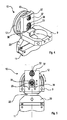
- Figure 1 is a perspective view of operating heads of a trimming machine provided with adjusting devices;
- Figure 2 is a fragmentary enlarged section of an adjusting device in Figure 1;
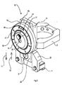
- Figure 3 is a perspective view of the adjusting device in Figure 2;
- Figure 4 is a further perspective view of the adjusting device in Figure 3;
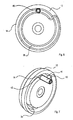
- Figure 5 is a rear view of the adjusting device in Figure 3;
- Figure 6 is a rear view showing some details of the adjusting device in Figure 3;
- Figure 7 is a perspective view of Figure 6.
- With reference to Figure 1, there are shown
operating heads 2 of atrimming machine 1 arranged for trimming an edge previously applied to a panel made of wood or similar material, which is not shown. - The mutually facing
operating heads 2 are arranged for machining an upper surface and a lower surface of the edge of the panel. - The
operating heads 2 are fixed toplates 4 that are vertically movable alongtube elements 8. - The
operating heads 2 comprise aspindle 5 arranged for supporting during rotation atrimming tool 6, for example a routing cutter provided withshaped plates 7. - With each of the
operating heads 2 there is further associated an adjustingdevice 10 fixed to thespindles 5 by means of a collar 9 (Figures 2 to 5). - The adjusting
device 10 is arranged for adjusting, in an initial adjusting step, a work position, with respect to a substantially vertical adjusting axis Z ofcopiers 11, with which thetrimming machine 1 is provided, andrespective trimming tools 6. - Depending on a position of the
copiers 11 and thetrimming tools 6, this enables a preset quantity of material to be removed from the edge of the panel. - In other words, the adjusting
device 10 enables a pass depth of thetrimming tool 6 to be adjusted in such a way that the latter removes a desired quantity of material from the edge of the panel and/or wear to theplates 7 of thetrimming tool 6 to be compensated for. - The
copiers 11 are fixed, through a threaded connection, to a substantially trapezoid copier-holder support 20. - The copier-
holder support 20 is associated, for example through ascrew 21, with aslide 22. - The
slide 22 with a substantially parallelpipedon shape with a rectangular base extends in use along a direction that is substantially parallel to the aforesaid adjusting axis Z and is provided with athrough hole 50. - The adjusting
device 10 further comprises anantirotation pin 23 engaging in thethrough hole 50, for example through interference. - The
antirotation pin 23 extending in a transverse direction to the aforesaid adjusting axis Z comprises afirst end 24 and asecond end 25. - The
first end 24 is provided with an internally threadedhole 26 whilst thesecond end 25 comprises an externally threadedportion 27. - The
first end 24 is arranged for rotationally supporting ahandwheel 12 having a substantially disc shape, between theantirotation pin 23 and thehandwheel 12 there being interposed abush 28. - The
handwheel 12 is provided with a knurledside surface 54 in such a way as to facilitate the handling thereof, and comprises a mutually oppositefirst face 13 andsecond face 14. - The
first face 13 comprises anannular surface 15 and acircular surface 16 that are concentric and positioned on parallel planes. - Between the
annular surface 15 and the circular surface 16 a substantiallycylindrical cavity 18 is defined. - The
annular surface 15 is arranged for receiving a graduatedscale element 17, whilst thecavity 18 is arranged for receiving, at least partially, a substantially disc-shaped locking element 19. - The
locking element 19, provided with areference incision 55, is fixed by means of afurther screw 30 to thefirst end 24 of thepin 23. - In this way, in use, the
handwheel 12 is interposed between thelocking element 19 and the copier-holder support 20. - The
locking element 19 is further provided with an arrestingscrew 31, having asurface 32 arranged for interacting with a portion of thecircular surface 16. - The
second face 14 of thehandwheel 12 comprises a groove 35 (Figures 6 and 7), spirally shaped, having a trapezoid profile section (Figure 2). - The
second end 25 of theantirotation pin 23 is arranged for passing through afurther hole 51 of asupport 37, that is fixed to thecollar 9. - The
support 37 is provided with aslot 36 that is substantially concentric on the aforesaidfurther hole 51. - The
second end 25 is coupled, through a threaded connection, to anut 38, opposite thefurther screw 30, and is arranged for sliding along a direction substantially parallel to the adjusting axis Z in theslot 36, between thenut 38 and theslot 36 there being interposed washer means 50'. - In this way, in use, the
slide 22 is interposed between thesupport 37 and thehandwheel 12. - The
support 37 is further provided with anotherhole 60 arranged for engaging with awedge 40 with which the adjustingdevice 10 is provided. - The
wedge 40 comprises an externally threadedside surface 41 and a substantiallyconical tip 42 arranged for engaging with thegroove 35 in such a way as to support thehandwheel 12 rotatingly in use. - The
wedge 40 is associated with thesupport 37 through afurther nut 52 and an adjustingbush 43, between thefurther nut 42 and the adjustingbush 43 there being interposed a washer 44. - In use, by tightening or loosening the
wedge 40 suitably with respect to the adjustingbush 43, it is possible to set a depth of penetration of thewedge 40 with respect to thegroove 35. - It should be noted that this allows the play between the
wedge 40 and thegroove 35 to be reduced, promoting micrometric adjustment of the adjustingdevice 10. - As said previously, the adjusting
device 10 is used in an initial adjusting step, before the trimmingmachine 1 performs trimming of the edge of the panel, to adjust the corresponding position along the adjusting axis Z between thecopiers 11 and thetrimming tools 6 in such a way as to determine a desired pass depth of the latter with respect to the edge of the panel. - The operation of the adjusting
device 10 is disclosed below. Due to a rotation of thehandwheel 12 with respect to thewedge 40, theantirotation pin 23 moves in theslot 36 along a direction substantially parallel to the adjusting axis Z, dragging with it theslide 22 and consequently thecopiers 11. - In this way it is possible to move the
copiers 11 away from or towards thetrimming tools 6 supported by thecollar 9 fixed to thesupport 37. - In particular, let an initial configuration be hypothesised in which the
trimming tools 6 are positioned with respect to thecopiers 11 in such a way as to machine the edge of a panel with a maximum radius of the shapedplates 7. - In this initial configuration, the graduated
scale 17 of thehandwheel 12 is, with respect to thereference incision 55, in a position indicated by the number "0". - If it is desired to diminish this radius, and therefore the pass depth of the trimming tools, it is sufficient to rotate the
handwheel 12 in the direction indicated by the arrow R2. - By doing so, the
copiers 11 are consequently moved in the direction indicated by the further arrow T2 moving them away, with respect to the adjusting axis Z, from thetrimming tools 6, increasing a distance D (Figure 2) between thecopiers 11 and therespective tools 6, measured along a direction parallel to the adjusting axis Z. - In other words, there exists a correspondence between a rotation angle of the
handwheel 12 and a movement along the adjusting axis Z of thecopiers 11. - Once the desired position has been reached, the arresting
screw 31 is used to lock thehandwheel 12 in this position. - It should be noted that the arresting
screw 31 acts as a safety element, inasmuch as the adjustingdevice 10 is irreversible, and thus prevents rectilinear movements of thecopiers 11 that are not generated by the voluntary rotation of thehandwheel 12, such as for example accidental blows. - On the other hand, if it is for example desired to compensate for the wear to the shaped
plates 7, and thus maintain unvaried the pass depth of thetrimming tools 6 despite the aforesaid wear, it is sufficient to rotate thehandwheel 12 in the direction indicated by the other arrow R1. - By doing so, the
copiers 11 are consequently moved in the direction indicated by the further other arrow T1, moving them, with respect to the adjusting axis Z, towards thetrimming tools 6, reducing the distance D. - Once the desired position has been reached, the arresting
screw 31 is used for locking thehandwheel 12 in this position. - In an embodiment of the invention, there is provided an adjusting device provided with a variable "0".
- It should be noted that in order to replicate the same pass depth on both surfaces of the panel it is necessary for the adjusting devices of the operating heads 2 to have the same adjustment.
- Once a mutual vertical position has been set of the
copiers 11 and thetrimming tools 6 it is possible to move the operating heads 2 vertically in such a way as to preload thecopiers 11 to improve the grip on the panel and resist machining stress. - Once the routing cutters have been driven, the
copiers 11 are vertically movable along an axis W, substantially parallel to the adjusting axis Z, fixed relative to the operating heads 2 and are arranged for tracing respectively an upper edge zone and a lower edge zone of the shaped panel in such a way as to detect the altimetric profile thereof. - In this way, in use, to a vertical movement of the
copiers 11 along the axis W, due to a height variation of the altimetric profile, there corresponds a vertical movement of equal amount of thetrimming tool 6. - In other words, the
copiers 11 set a work height for thetrimming tool 6 in function of the altimetric profile detected instant by instant.
Claims (32)
- Adjusting device arranged for adjusting a position, with respect to an adjusting axis (Z), of a first element (11) with respect to a second element (6), said first element (11) being supported by slide means (22) movable along said adjusting axis (Z) with respect to said second element (6), characterised in that said device comprises handwheel means (12) rotatable with respect to said slide means (22), said handwheel means (12) comprising shaped groove means (35) rotationally engaging with pin means (40) fixed along said adjusting axis (Z) with respect to said second element (6).
- Device according to claim 1, wherein said pin means comprises wedge means (40).
- Device according to claim 1, or 2, wherein said shaped groove means (35) has a spiral shape.
- Device according to any preceding claim, wherein said shaped groove means (35) has in cross section a profile having a substantially trapezium shape.
- Device according to any one of claims 2 to 4, wherein said wedge means (40) comprises a substantially conical tip (42).
- Device according to any one of claims 2 to 5, and further comprising setting means (43) engaging with said wedge means (40) and arranged for adjusting a penetration depth of said wedge means (40) with respect to said shaped groove means (35).
- Device according to any preceding claim, wherein said handwheel means (12) is associated with antirotation pin means (23) fixed to said slide means (22) arranged for preventing rotation of said slide means (22) with respect to said pin means (40).
- Device according to claim 7, wherein said antirotation pin means (23) is constrained to slide along a direction substantially parallel to said adjusting axis (Z) in guide means (36).
- Device according to claim 8, wherein said guide means (36) is obtained in supporting means (37) arranged for supporting said pin means (40).
- Device according to claim 9, wherein said supporting means (37) is associated with collar means (9) arranged for supporting said second element (6).
- Device according to any preceding claim, wherein said adjusting axis (Z) is a substantially vertical axis.
- Device according to any preceding claim, wherein said handwheel means (12) comprises graduated scale means (17).
- Device according to any preceding claim, and further comprising locking means (31) arranged for locking said handwheel means (12) in a desired position.
- Device according to any preceding claim, wherein said first element is a copier (11) of a trimming machine (1) of edged panels.
- Device according to claim 14, wherein said second element is a trimming tool (6) of said trimming machine (1).
- Adjusting device of a trimming machine (1) of edged panels comprising adjusting means (10) arranged for adjusting a corresponding position, with respect, to an adjusting axis (Z), of a copier (11) with respect to a finishing tool (6), characterised in that said adjusting means comprises continuous adjusting means (10).
- Device according to claim 16, wherein said continuous adjusting means (10) comprises slide means (22) movable along said adjusting axis (Z) with respect to said trimming tool (6) and arranged for supporting said copier (11).
- Device according to claim 17, wherein said continuous adjusting means (10) comprises handwheel means (12) associated to said slide means (22).
- Device according to claim 18, wherein said handwheel means (12) comprises shaped groove means (35).
- Device according to claim 19, wherein said shaped groove means (35) is arranged for engaging rotationally with pin means (40) fixed along said adjusting axis (Z) with respect to said trimming tool (6).
- Apparatus according to claim 20, wherein said pin means comprises wedge means (40).
- Device according to any one of claims 19 to 21, wherein said shaped groove means (35) has a spiral shape.
- Device according to any one of claims 19 to 22, wherein said shaped groove means (35) has in cross section a profile having a substantially trapezium shape.
- Device according to any one of claims 21 to 23, wherein said wedge means (40) comprises a substantially conical tip (42).
- Device according to any one of claims 21 to 24, and further comprising setting means (43) engaging with said wedge means (40) and arranged for adjusting a penetration depth of said wedge means (40) with respect to said shaped groove means (35).
- Device according to any one of claims 20 to 25, wherein said handwheel means (12) is associated with antirotation pin means (23) fixed to said slide means (22) arranged for preventing rotation of said slide means (22) with respect to said pin means (40).
- Device according to claim 26, wherein said antirotation pin means (23) is constrained to slide along a direction substantially parallel to said adjusting axis (Z) in guide means (36).
- Device according to claim 27, wherein said guide means (36) is obtained in supporting means (37) arranged for supporting said pin means (40).
- Device according to claim 28, wherein said supporting means (37) is associated with collar means (9) arranged for supporting said trimming tool (6).
- Device according to any one of claims 16 to 29, wherein said adjusting axis (Z) is a substantially vertical axis.
- Device according to any one of claims 18 to 29, or according to claim 30 as appended to any one of claims 18 to 29, wherein said handwheel means (12) comprises graduated scale means (17).
- Device according to any one of claims 18 to 29, or according to claim 30 as appended to any one of claims 18 to 29, or according to claim 31, and further comprising locking means (31) arranged for locking said handwheel means (12) in a desired position.
Applications Claiming Priority (1)
| Application Number | Priority Date | Filing Date | Title |
|---|---|---|---|
| ITMO20050296 ITMO20050296A1 (en) | 2005-11-10 | 2005-11-10 | ADJUSTMENT DEVICE |
Publications (3)
| Publication Number | Publication Date |
|---|---|
| EP1785226A2 true EP1785226A2 (en) | 2007-05-16 |
| EP1785226A3 EP1785226A3 (en) | 2007-06-06 |
| EP1785226B1 EP1785226B1 (en) | 2009-09-09 |
Family
ID=37663286
Family Applications (1)
| Application Number | Title | Priority Date | Filing Date |
|---|---|---|---|
| EP20060023277 Not-in-force EP1785226B1 (en) | 2005-11-10 | 2006-11-09 | Adjusting device |
Country Status (3)
| Country | Link |
|---|---|
| EP (1) | EP1785226B1 (en) |
| DE (1) | DE602006009047D1 (en) |
| IT (1) | ITMO20050296A1 (en) |
Citations (2)
| Publication number | Priority date | Publication date | Assignee | Title |
|---|---|---|---|---|
| FR2559086A1 (en) | 1984-02-06 | 1985-08-09 | Sticht Walter | DEVICE FOR POSITIONING OR RESPECTIVELY BLOCKING PARTS |
| EP0997245A2 (en) | 1998-10-30 | 2000-05-03 | SCM GROUP S.p.A. | A panel edge machining unit |
Family Cites Families (2)
| Publication number | Priority date | Publication date | Assignee | Title |
|---|---|---|---|---|
| GB120997A (en) * | 1917-12-13 | 1918-12-05 | George William Mcwilliam | Improvements in Feeding Mechanism for the Cutting Tools of Lathes and similar Machines. |
| DE4216763C2 (en) * | 1992-05-21 | 1999-09-23 | Werkzeug Gmbh | Copy turning device |
-
2005
- 2005-11-10 IT ITMO20050296 patent/ITMO20050296A1/en unknown
-
2006
- 2006-11-09 EP EP20060023277 patent/EP1785226B1/en not_active Not-in-force
- 2006-11-09 DE DE200660009047 patent/DE602006009047D1/en active Active
Patent Citations (2)
| Publication number | Priority date | Publication date | Assignee | Title |
|---|---|---|---|---|
| FR2559086A1 (en) | 1984-02-06 | 1985-08-09 | Sticht Walter | DEVICE FOR POSITIONING OR RESPECTIVELY BLOCKING PARTS |
| EP0997245A2 (en) | 1998-10-30 | 2000-05-03 | SCM GROUP S.p.A. | A panel edge machining unit |
Also Published As
| Publication number | Publication date |
|---|---|
| EP1785226A3 (en) | 2007-06-06 |
| DE602006009047D1 (en) | 2009-10-22 |
| ITMO20050296A1 (en) | 2007-05-11 |
| EP1785226B1 (en) | 2009-09-09 |
Similar Documents
| Publication | Publication Date | Title |
|---|---|---|
| EP2338640B1 (en) | Machine for grinding optical workpieces, in particular plastic eyeglass lenses | |
| US9682454B2 (en) | Micro-adjustable flip-away work stop for strut systems | |
| KR101883211B1 (en) | an alignment apparatus for a jig of machine tool | |
| US11565359B2 (en) | Positioning and centering device, system, and method for use with a template guidance system for a pantograph router | |
| SE444986B (en) | DEVICE FOR INBOARD CENTERING OF A CENTER SPINDLE INCLUDED IN THE DEVICE AND A HALL IN A FORM | |
| EP1785226B1 (en) | Adjusting device | |
| KR102081544B1 (en) | A Rod Processing Apparatus | |
| US3762247A (en) | Tool adjustment mechanisms for a lathe | |
| DE3630010A1 (en) | Steady rest, in particular for cylindrical grinding machines | |
| JP2818629B2 (en) | Method and apparatus for changing settings of a processing machine | |
| US12409501B2 (en) | Guide dresser, cutter heads and methods of use thereof | |
| KR20160077713A (en) | Device for setting up work of mechanical machining | |
| EP0419754B1 (en) | Apparatus for cutting a flat material | |
| US4480410A (en) | Precision center lapping apparatus and method | |
| US3299752A (en) | Tool holder construction | |
| EP0213361B1 (en) | Machine tool working by chipping | |
| EP0314333A2 (en) | Apparatus for measuring and correcting machining dimensions | |
| US3928943A (en) | Device for the feed of grinding tools to grinding machines | |
| US3785245A (en) | Multi-curve generator | |
| US7984563B2 (en) | Device for determining a distance from a reference surface | |
| EP0394209A2 (en) | Improvement in and relating to grinding machines | |
| US4317395A (en) | Lathe stop | |
| KR101606194B1 (en) | Fixing device for manufacturing edge angle of drill | |
| CN110370086A (en) | A kind of valve cock lathe for machining | |
| US3085370A (en) | Combined dressing tool and work piece holder |
Legal Events
| Date | Code | Title | Description |
|---|---|---|---|
| PUAI | Public reference made under article 153(3) epc to a published international application that has entered the european phase |
Free format text: ORIGINAL CODE: 0009012 |
|
| PUAL | Search report despatched |
Free format text: ORIGINAL CODE: 0009013 |
|
| AK | Designated contracting states |
Kind code of ref document: A2 Designated state(s): AT BE BG CH CY CZ DE DK EE ES FI FR GB GR HU IE IS IT LI LT LU LV MC NL PL PT RO SE SI SK TR |
|
| AX | Request for extension of the european patent |
Extension state: AL BA HR MK YU |
|
| AK | Designated contracting states |
Kind code of ref document: A3 Designated state(s): AT BE BG CH CY CZ DE DK EE ES FI FR GB GR HU IE IS IT LI LT LU LV MC NL PL PT RO SE SI SK TR |
|
| AX | Request for extension of the european patent |
Extension state: AL BA HR MK YU |
|
| 17P | Request for examination filed |
Effective date: 20071206 |
|
| 17Q | First examination report despatched |
Effective date: 20080109 |
|
| AKX | Designation fees paid |
Designated state(s): DE FR IT |
|
| GRAP | Despatch of communication of intention to grant a patent |
Free format text: ORIGINAL CODE: EPIDOSNIGR1 |
|
| GRAS | Grant fee paid |
Free format text: ORIGINAL CODE: EPIDOSNIGR3 |
|
| GRAA | (expected) grant |
Free format text: ORIGINAL CODE: 0009210 |
|
| AK | Designated contracting states |
Kind code of ref document: B1 Designated state(s): DE FR IT |
|
| REF | Corresponds to: |
Ref document number: 602006009047 Country of ref document: DE Date of ref document: 20091022 Kind code of ref document: P |
|
| PLBE | No opposition filed within time limit |
Free format text: ORIGINAL CODE: 0009261 |
|
| STAA | Information on the status of an ep patent application or granted ep patent |
Free format text: STATUS: NO OPPOSITION FILED WITHIN TIME LIMIT |
|
| 26N | No opposition filed |
Effective date: 20100610 |
|
| REG | Reference to a national code |
Ref country code: FR Ref legal event code: ST Effective date: 20100730 |
|
| PG25 | Lapsed in a contracting state [announced via postgrant information from national office to epo] |
Ref country code: FR Free format text: LAPSE BECAUSE OF NON-PAYMENT OF DUE FEES Effective date: 20091130 |
|
| PGFP | Annual fee paid to national office [announced via postgrant information from national office to epo] |
Ref country code: DE Payment date: 20161205 Year of fee payment: 11 |
|
| PGFP | Annual fee paid to national office [announced via postgrant information from national office to epo] |
Ref country code: IT Payment date: 20161130 Year of fee payment: 11 |
|
| REG | Reference to a national code |
Ref country code: DE Ref legal event code: R119 Ref document number: 602006009047 Country of ref document: DE |
|
| PG25 | Lapsed in a contracting state [announced via postgrant information from national office to epo] |
Ref country code: IT Free format text: LAPSE BECAUSE OF NON-PAYMENT OF DUE FEES Effective date: 20171109 Ref country code: DE Free format text: LAPSE BECAUSE OF NON-PAYMENT OF DUE FEES Effective date: 20180602 |