EP0394209A2 - Improvement in and relating to grinding machines - Google Patents
Improvement in and relating to grinding machines Download PDFInfo
- Publication number
- EP0394209A2 EP0394209A2 EP90850142A EP90850142A EP0394209A2 EP 0394209 A2 EP0394209 A2 EP 0394209A2 EP 90850142 A EP90850142 A EP 90850142A EP 90850142 A EP90850142 A EP 90850142A EP 0394209 A2 EP0394209 A2 EP 0394209A2
- Authority
- EP
- European Patent Office
- Prior art keywords
- tables
- upper table
- engagement
- lower table
- grinding machine
- Prior art date
- Legal status (The legal status is an assumption and is not a legal conclusion. Google has not performed a legal analysis and makes no representation as to the accuracy of the status listed.)
- Granted
Links
Images


Classifications
-
- B—PERFORMING OPERATIONS; TRANSPORTING
- B23—MACHINE TOOLS; METAL-WORKING NOT OTHERWISE PROVIDED FOR
- B23Q—DETAILS, COMPONENTS, OR ACCESSORIES FOR MACHINE TOOLS, e.g. ARRANGEMENTS FOR COPYING OR CONTROLLING; MACHINE TOOLS IN GENERAL CHARACTERISED BY THE CONSTRUCTION OF PARTICULAR DETAILS OR COMPONENTS; COMBINATIONS OR ASSOCIATIONS OF METAL-WORKING MACHINES, NOT DIRECTED TO A PARTICULAR RESULT
- B23Q1/00—Members which are comprised in the general build-up of a form of machine, particularly relatively large fixed members
- B23Q1/25—Movable or adjustable work or tool supports
- B23Q1/26—Movable or adjustable work or tool supports characterised by constructional features relating to the co-operation of relatively movable members; Means for preventing relative movement of such members
- B23Q1/30—Movable or adjustable work or tool supports characterised by constructional features relating to the co-operation of relatively movable members; Means for preventing relative movement of such members controlled in conjunction with the feed mechanism
-
- B—PERFORMING OPERATIONS; TRANSPORTING
- B23—MACHINE TOOLS; METAL-WORKING NOT OTHERWISE PROVIDED FOR
- B23Q—DETAILS, COMPONENTS, OR ACCESSORIES FOR MACHINE TOOLS, e.g. ARRANGEMENTS FOR COPYING OR CONTROLLING; MACHINE TOOLS IN GENERAL CHARACTERISED BY THE CONSTRUCTION OF PARTICULAR DETAILS OR COMPONENTS; COMBINATIONS OR ASSOCIATIONS OF METAL-WORKING MACHINES, NOT DIRECTED TO A PARTICULAR RESULT
- B23Q5/00—Driving or feeding mechanisms; Control arrangements therefor
-
- B—PERFORMING OPERATIONS; TRANSPORTING
- B24—GRINDING; POLISHING
- B24B—MACHINES, DEVICES, OR PROCESSES FOR GRINDING OR POLISHING; DRESSING OR CONDITIONING OF ABRADING SURFACES; FEEDING OF GRINDING, POLISHING, OR LAPPING AGENTS
- B24B47/00—Drives or gearings; Equipment therefor
- B24B47/22—Equipment for exact control of the position of the grinding tool or work at the start of the grinding operation
-
- B—PERFORMING OPERATIONS; TRANSPORTING
- B24—GRINDING; POLISHING
- B24B—MACHINES, DEVICES, OR PROCESSES FOR GRINDING OR POLISHING; DRESSING OR CONDITIONING OF ABRADING SURFACES; FEEDING OF GRINDING, POLISHING, OR LAPPING AGENTS
- B24B47/00—Drives or gearings; Equipment therefor
- B24B47/26—Accessories, e.g. stops
Definitions
- the present invention relates to a method of making computer-controlled adjustments to the settings of grinding machines, and particularly to cylindrical grinding machines, when grinding workpieces of varying dimensions, and more specifically to a method of the kind set forth in the preamble of Claim 1.
- the invention also relates to a computer-controlled grinding machine, and particularly, but not exclusively, to a computer-controlled grinding machine, and more particularly, but not exclusively, to a cylindrical grinding machine of the kind set forth in the preamble of Claim 4.
- Such machines normally include two or more machine members supported respectively on upper and lower tables, these machine members possibly comprising measuring apparatus, grindstone sharpening devices and internal-grinding devices, in addition to a work head, steady rest or tailstock.
- GB,A,2.153.270 (Schaudt) teaches a computer-controlled grinding machine which includes a facility for releasably locking a center-point tailstock.
- the tailstock is not carried by an upper table, however, and there is a danger that dirt, cutting fluid, etc. will collect in the region of the locking devices and clamping surfaces.
- US,A,4.221.080 (Favrot) teaches a twin-table machine comprising an upper and a lower table for a work spindle and a center-point tailstock respectively, these members being mounted for movement on one and the same slide.
- the relative movement between the tables for the purpose of clamping and releasing a workpiece is effected hydraulically.
- the tables are moved in unison with the aid of servo motors.
- US,A,2.356.839 also teaches a grinding machine construction in which the work head and tailstock can be moved relative to one another.
- the work head and tailstock spindle can also be locked together and are arranged to move axially in unison.
- the construction is relatively complicated, however, and is not intended to permit automated resetting of the machine.
- DE,A,1.602.934 (Okuma Machinery Works) describes an engine lathe in which the axial position of a centerpoint tailstock can be reset automatically. This positional resetting of the tailstock spindle is controlled by a measuring device operative to detect the length of the workpiece concerned. The tailstock spindle and the work head do not move in unison. Instead, the lathe tool moves axially, as is normal with engine lathes.
- one object of this invention is to provide a method and an arrangement of the aforesaid kind by means of which adjustments can be made to the settings of a grinding machine in a reliable manner, with the aid of computerized control means, even when grinding workpieces of varying sizes, thereby enabling the entire grinding cycle or "machine-setup" to be preprogrammed.
- the operator need only select from the alternatives available on the computer button-bank that alternative or those alternatives which corresponds or correspond to the workpiece concerned, whereupon the entire working operation, including adjustments to machine alignment settings? when grinding workpieces of varying dimensions takes place automatically and is computer-controlled in accordance with the program selected.
- the invention also relates to a computer-controlled grinding machine, the main characteristic features of which are set forth in the characterizing clause of Claim 4.
- One important member of the inventive grinding machine is the releasable locking device by means of which the upper and lower tables are held together.
- a suitable configuration of this locking device is disclosed in Claim 5.
- the elements forming from which the locking device is formed will not give rise to oblique or asymetric engagement forces liable to cause one table to move laterally relative to the other and therewith impair grinding.
- the locking elements of said locking device are disposed symmetrically and engage an elongated element, e.g. a straight edge, mounted on the other of said tables, on mutually opposite sides of the straight edge.
- Locking shoulders of the kind stated and carried on excentric shafts make possible accurate locking engagement in any relative position and also enable the locking device to be released immediately and quickly when so desired.
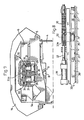
- Figure 1 illustrates a cylindrical grinding machine 1 and a cabinet 2 which houses computer and control equipment.
- a lower table or work platen 5 is mounted in V-guides and plain guides for axial movement on the bed-slide 4.
- the lower table 5 is provided in turn with V-guides 5a and plain guides 5b for guiding an upper table 6.
- the upper table 6 is joined mechanically to the lower table 5 by means of a specially designed locking device, hereinafter described with reference to Figures 5-8.
- the lower table is driven by means of a drive arrangement comprising a so-called ball screw 8 which engages in a nut 9 (shown for instance in Figure 2) mounted on the upper table.
- the ball screw 8 is driven by a motor 11 with the aid of a toothed belt 12 passing around a spocket wheel 13.
- a pulse emitter 14 connected to the screw 8 generates pulses in response to rotation of the screw. These pulses are sent to an arithmetic or counter mechanism in the control system, so that the exact position of the lower table, and therewith also the upper table, can be determined at any given moment to an accuracy of 1/1000 mm.
- the work head is adjusted to those grinding operations for which the machine is intended.
- the work head has a rigid, non-rotating spindle. This type of spindle provides the best stability for grinding operations between the work head and tailstock.
- the machine illustrated in Figure 1 may be provided with other types of stocks, measuring equipment, grinding-wheel-sharpening means or internal-grinding means, in addition to the illustrated work head and tailstock.
- the grinding wheel is referenced 20
- a grinding wheel guard is referenced 21
- a nozzle for delivering cutting fluid is referenced 22.
- a channel system for electric cables extending between the cabinet 2 and the grinding machine 1 is referenced 23.
- a table-engagement device 25 having an engagement member 25a which is operative to engage a recess 6a provided in the upper table 6 for this purpose.
- the engagement device 25 is biased by a spring towards its position of engagement and is so configured as to accurately determine the position of the upper table. Movement towards and away from the release position is effected under the influence of a pressure fluid.
- the engagement means 25a will hold the upper table in a predetermined position, provided that the locking device hereinafter described and acting between the two tables is released.
- FIG. 7 The configuration of the locking device is shown in Figures 7 and 8.
- a plate 30 which carries journals 34 for two excentric shafts 31.
- the upper part of each of the shafts 31 engages, via a respective gear wheel 32, a rack-part 33a of a piston rod 33.
- Each of the excentric shafts 31 carries on its lower end a locking shoulder 35. These locking shoulders engage an elongated straight edge 36 connected to the lower table 5 from mutually opposite sides of said straight edge.
- the straight edge 36 is guided on guide keys 37 disposed between the lower table 5 and the straight edge.
- Displacement of the piston rod 33 for the purpose of releasing the locking shoulders 35 is effected by means of a piston-cylinder device 38, which moves the piston rod towards a pack of cup springs 39.
- the arrangement is such that the spring pack 39 will always return the locking shoulders 35 into locking engagement, should the drive means 38 malfunction.
- Figure 1 illustrates a workpiece 40 clamped between the work head 16 and a center-point tailstock 17.
- the workpiece is machined by the grinding wheel 20.
- the workpiece 40 comprises a shaft which exhibits several diameters. Small numbers of such shafts of varying dimensions are to be ground in the machine, which necessitates a new setup, i.e. relative movement between the work head 16 and the tailstock 17 to a new working position, in addition to removing a workpiece and inserting a new workpiece.
- This adjustment to the machine settings can be achieved by means of the computer and control system of the machine, when practicing the inventive method.
- Figures 2-4 illustrate the general procedure carried-out when effecting adjustments to machine settings.
- the ball screw 8 then begins to rotate in an opposite direction, so as to move the lower table to the left.
- the upper table 6 moves together with the lower table - despite the fact that the locking device has been released - as a result of the friction acting between the tables.
- the engagement member 25a engages and holds the upper table 6.
- the lower table 5 continues to move to the left.
- the lower table then reaches a terminal position in which the direction of table-movement is reversed.
- the table continues to move to the right through a given distance, until the lower table is in a position in which the work head 16 and the tailstock 17 are located at a predetermined distance apart.
- the lower table 5 is stopped in this position, and the locking device is returned to its locking position, whereas the engagement member 25a moves to its released position, so that the upper table can pass the engagement means without coming into engagement therewith.
- the lower and upper tables have therewith been set to desired relative positions.
- Figure 4 illustrates two position indicators 42 and 43 which, in co-action with blocks or corresponding projections 44 and 45 respectively produce 0-position signals representative of the relative movement between the bed 4 and the lower table 5 and between the lower table 5 and the upper table 6 respectively.
- the machine control equipment is then able to position the upper table 6 in relation to the lower table 5 very accurately with the aid of these 0-position signals and the pulse emitter 14.
- the lower table may be optionally moved immediately to its predetermined, new position, i.e. without first passing a terminal position when the direction of movement is reversed. Passage of the lower table through terminal positions of the kind stated, however, will afford certain advantages which facilitate the guidance of table movement via the computer-control arrangement.
Landscapes
- Engineering & Computer Science (AREA)
- Mechanical Engineering (AREA)
- Constituent Portions Of Griding Lathes, Driving, Sensing And Control (AREA)
- Jigs For Machine Tools (AREA)
- Finish Polishing, Edge Sharpening, And Grinding By Specific Grinding Devices (AREA)
Abstract

Description
- The present invention relates to a method of making computer-controlled adjustments to the settings of grinding machines, and particularly to cylindrical grinding machines, when grinding workpieces of varying dimensions, and more specifically to a method of the kind set forth in the preamble of Claim 1.
- The invention also relates to a computer-controlled grinding machine, and particularly, but not exclusively, to a computer-controlled grinding machine, and more particularly, but not exclusively, to a cylindrical grinding machine of the kind set forth in the preamble of Claim 4.
- Such machines normally include two or more machine members supported respectively on upper and lower tables, these machine members possibly comprising measuring apparatus, grindstone sharpening devices and internal-grinding devices, in addition to a work head, steady rest or tailstock.
- In known computer-controlled grinding machines of the kind intended here, the operator is able to effect relevant changes to the grinding process through the intermediary of a button bank provided on a machine console, these changes being occasioned by changes in workpiece geometry and workpiece grinding data. A number of the steps involved in the work of resetting the machine when grinding workpieces of varying dimensions, however, must be carried out manually. One example of this is the time-consuming precision work required to measure and adjust the relative distances between reference points on the machine members carried by the tables. These adjustments cannot be previously programmed, but are left to the responsibility and expertise of the operator concerned.
- One requisite for modern manufacture to be profitable is that a smaller number of one particular product is worked at any one time. This tends to result in smaller batch numbers, which in turn leads to a greater number of resetting operations accompanied by greater demands on the operator and in higher costs for the non-programmable resetting work required.
- It will therefore be seen that the possibility of automated, computer-controlled resetting of grinding machines which will enable the grinding cycle to be programmed in a computer herefore is highly desirable.
- GB,A,2.153.270 (Schaudt) teaches a computer-controlled grinding machine which includes a facility for releasably locking a center-point tailstock. The tailstock is not carried by an upper table, however, and there is a danger that dirt, cutting fluid, etc. will collect in the region of the locking devices and clamping surfaces.
- US,A,3.803.770 (Abraham) teaches a grinding machine provided with an upper and a lower table, each of said tables being equipped with separate drive means.
- US,A,4.221.080 (Favrot) teaches a twin-table machine comprising an upper and a lower table for a work spindle and a center-point tailstock respectively, these members being mounted for movement on one and the same slide. The relative movement between the tables for the purpose of clamping and releasing a workpiece is effected hydraulically. The tables are moved in unison with the aid of servo motors.
- US,A,2.576.497 (Austin, et al) teaches a grinding machine construction in which the work head and the tailstock can be moved axially in relation to one another, with the aid of a mechanism intended therefor. There is no facility for common, simultaneous displacement of these two machine members, however.
- US,A,2.356.839 (Flanders) also teaches a grinding machine construction in which the work head and tailstock can be moved relative to one another. The work head and tailstock spindle can also be locked together and are arranged to move axially in unison. The construction is relatively complicated, however, and is not intended to permit automated resetting of the machine.
- DE,A,1.602.934 (Okuma Machinery Works) describes an engine lathe in which the axial position of a centerpoint tailstock can be reset automatically. This positional resetting of the tailstock spindle is controlled by a measuring device operative to detect the length of the workpiece concerned. The tailstock spindle and the work head do not move in unison. Instead, the lathe tool moves axially, as is normal with engine lathes.
- However, none of the aforesaid head stock and tailstock arrangements known in connection with grinding machines and like machines enable computer-controlled resetting of the machine in the aforedescribed fashion, such that the entire grinding cycle can be previously programmed in computerized control apparatus.
- Accordingly, one object of this invention is to provide a method and an arrangement of the aforesaid kind by means of which adjustments can be made to the settings of a grinding machine in a reliable manner, with the aid of computerized control means, even when grinding workpieces of varying sizes, thereby enabling the entire grinding cycle or "machine-setup" to be preprogrammed.
- Another object is to provide a method and a grinding machine which will satisfy high accuracy requirements in conjunction with grinding operations.
- These and other objects are realized by the inventive method, the main characteristic features of which are set forth in the characterizing clause of Claim 1.
- Because adjustments to the machine settings are effected with the aid of a bridge-like yoke, which is connected to the lower table and which carries workpiece-clamping means and/or some corresponding means in spaced relationship above the upper table, free relative movement is afforded between the upper and the lower table without hinderance from components or machine members carried by said lower table.
- The fact that only one single drive means is used to move the tables in unison until the upper table is brought into contact with the table-engagement device and gripped and held by said device, simplifies the machine drive system and also improves the accuracy with which the tables can be positioned relative to one another. The position taken by the upper table when gripped and held by the table-engagement device provides an accurately defined reference point from which continued movement of the lower table to its selected reference position can be determined with great precision.
- It is unnecessary to determine the relative positions of the tables in particular, since the computer operative to control table movements constantly has access to data representative of the positions of different relevant reference points. This particular advantage leads to the possibility afforded by the invention of also automating and computer-controlling the actual resetting operation itself, i.e. so as to enable the entire grinding cycle to be programmed and automated.
- In practice, the operator need only select from the alternatives available on the computer button-bank that alternative or those alternatives which corresponds or correspond to the workpiece concerned, whereupon the entire working operation, including adjustments to machine alignment settings? when grinding workpieces of varying dimensions takes place automatically and is computer-controlled in accordance with the program selected.
- It is preferred in practice to apply the inventive method set forth in
Claim 2. Because the upper and lower tables, whilst being locked together, move in unison to a reference point of the kind stated, for instance to a terminal position in which the direction of table movement is reversed, it is possible to determine the positional settings of the machine members in a positive manner with the accuracy presumed in accordance with the invention. The upper and lower tables move away from this predetermined position in unison without being mechanically locked in engagement with one another and being joined solely as a result of mutual frictional engagement, since the upper table rests on the lower table. This simultaneous movement continues until the upper table is engaged by the table-engagement device. It is possible, in this way, to determine clearly and unambiguously an upper-table reference point, while movement of the lower table in relation to this reference point is determined to precise values in a corresponding manner. When the lower table has reached a predetermined relative position, the tables are again connected mechanically by means of the locking device. It will be seen that the use of one single drive means provides the high degree of accuracy desired in the movement pattern and also facilitates the possibility of programming and computer-controlling adjustments to the settings of the grinding machine. - In some cases, it is preferred to move the lower table to said predetermined position in the manner described in
Claim 3, i.e. with passage of the table to one terminal position, at which the direction of movement is reversed. This enables accuracy to be improved, since a terminal point of the kind stated can be defined very precisely. The accuracy at which positions are determined can be improved when starting from this reference point. - The invention also relates to a computer-controlled grinding machine, the main characteristic features of which are set forth in the characterizing clause of Claim 4.
- One important member of the inventive grinding machine is the releasable locking device by means of which the upper and lower tables are held together. A suitable configuration of this locking device is disclosed in
Claim 5. Thus, it is important that the elements forming from which the locking device is formed will not give rise to oblique or asymetric engagement forces liable to cause one table to move laterally relative to the other and therewith impair grinding. - It is also essential that the locking elements of said locking device are disposed symmetrically and engage an elongated element, e.g. a straight edge, mounted on the other of said tables, on mutually opposite sides of the straight edge.
- This elongated element, e.g. the straight edge, shall be held against axial movement, but guided for movement in the transverse direction of the table carrying said element. These transverse movements are, of course, very small, but impaired grinding can be avoided when such small transverse movements are permitted.
- Further advantage characteristic features of the locking device are disclosed in
Claim 6 and 7. Locking shoulders of the kind stated and carried on excentric shafts make possible accurate locking engagement in any relative position and also enable the locking device to be released immediately and quickly when so desired. - Further characteristic features of the inventive method and grinding machine will be evident from the following description of a preferred embodiment of the invention illustrated in the accompanying drawings, in which
- Figure 1 is a perspective view of a cylindrical grinding machine and an associated cabinet which houses computer and control equipment;
- Figures 2-4 illustrate schematically and principally and in perspective different relative positions between the upper and lower tables when making computer-controlled changes to the settings of the grinding machine;
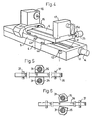
- Figure 5 illustrates part of a locking device from beneath, said locking device being operative to join the upper and lower tables together with the aid of two symmetrical locking shoulders in locking engagement with a straight edge;
- Figure 6 is a view similar to Figure 5, but with the locking shoulders released from their engagement with the straight edge;
- Figure 7 is a partly cut-away front view which illustrates the grinding-machine bed, the lower table, an associated bridge-like yoke, the upper table, and the locking mechanism which joins the two tables together; and
- Figure 8 is a partly cut-away side view of the locking mechanism and associated locking-mechanism drive means.
- Figure 1 illustrates a cylindrical grinding machine 1 and a
cabinet 2 which houses computer and control equipment. - The machine frame has a
bed 3 and a bed slide 4 of stable construction. - A lower table or
work platen 5 is mounted in V-guides and plain guides for axial movement on the bed-slide 4. - The lower table 5 is provided in turn with V-
guides 5a andplain guides 5b for guiding an upper table 6. The upper table 6 is joined mechanically to the lower table 5 by means of a specially designed locking device, hereinafter described with reference to Figures 5-8. - The lower table is driven by means of a drive arrangement comprising a so-called
ball screw 8 which engages in a nut 9 (shown for instance in Figure 2) mounted on the upper table. - The
ball screw 8 is driven by amotor 11 with the aid of atoothed belt 12 passing around aspocket wheel 13. Apulse emitter 14 connected to thescrew 8 generates pulses in response to rotation of the screw. These pulses are sent to an arithmetic or counter mechanism in the control system, so that the exact position of the lower table, and therewith also the upper table, can be determined at any given moment to an accuracy of 1/1000 mm. - The
drive motor 11 is a servo motor, which enables the table to be positioned quickly and exactly, by manually pressing the appropriate buttons and by means of a program for automatic grinding cycles in multi-diameter and length grinding operations. The illustrated grinding machine includes awork head 16 which is carried by the lower table 5 through the intermediary of a bridgingyoke 15 which extends to a point above the upper table 6. The upper table 6 carries atailstock 17 provided either with a spindle or with a center-point. - The work head is adjusted to those grinding operations for which the machine is intended. In its simplest form, the work head has a rigid, non-rotating spindle. This type of spindle provides the best stability for grinding operations between the work head and tailstock.
- The upper table 6 carries a
tailstock 17, which can be readily moved subsequent to backing-off clamping screws (not shown). - The machine illustrated in Figure 1 may be provided with other types of stocks, measuring equipment, grinding-wheel-sharpening means or internal-grinding means, in addition to the illustrated work head and tailstock.
- In the Figure 1 illustration, the grinding wheel is referenced 20, a grinding wheel guard is referenced 21 and a nozzle for delivering cutting fluid is referenced 22. A channel system for electric cables extending between the
cabinet 2 and the grinding machine 1 is referenced 23. - Also illustrated in Figure 1 is a table-
engagement device 25 having an engagement member 25a which is operative to engage a recess 6a provided in the upper table 6 for this purpose. Theengagement device 25 is biased by a spring towards its position of engagement and is so configured as to accurately determine the position of the upper table. Movement towards and away from the release position is effected under the influence of a pressure fluid. - The engagement means 25a will hold the upper table in a predetermined position, provided that the locking device hereinafter described and acting between the two tables is released.
- The configuration of the locking device is shown in Figures 7 and 8. Provided in the upper table 6 is a
plate 30 which carriesjournals 34 for twoexcentric shafts 31. The upper part of each of theshafts 31 engages, via arespective gear wheel 32, a rack-part 33a of apiston rod 33. - Each of the
excentric shafts 31 carries on its lower end a lockingshoulder 35. These locking shoulders engage an elongatedstraight edge 36 connected to the lower table 5 from mutually opposite sides of said straight edge. - It is essential that no transverse or obliquely acting forces capable of displacing one of the tables 5, 6 laterally in relation to the other can occur, and consequently the locking shoulders 35 engage mutually opposite sides of the
straight edge 36 symmetrically. - The
straight edge 36 is rigid in its axial direction and is able to perform given lateral movements, in order to eliminate the risk of the effect of transverse forces of the aforesaid kind. - As will be seen from Figure 8, the
straight edge 36 is guided onguide keys 37 disposed between the lower table 5 and the straight edge. - Displacement of the
piston rod 33 for the purpose of releasing the locking shoulders 35 is effected by means of a piston-cylinder device 38, which moves the piston rod towards a pack of cup springs 39. The arrangement is such that thespring pack 39 will always return the locking shoulders 35 into locking engagement, should the drive means 38 malfunction. - Co-action of the locking shoulders 35 with the
straight edge 36 is illustrated in Figures 5 and 6, of which Figure 5 illustrates the locking shoulders in their positions of engagement with thestraight edge 36, whereas Figure 6 illustrates the locking shoulders in their released positions. The locking shoulders achieve accurate and reliable engagement with the straight edge. - Figure 1 illustrates a
workpiece 40 clamped between thework head 16 and a center-point tailstock 17. The workpiece is machined by the grindingwheel 20. - The
workpiece 40 comprises a shaft which exhibits several diameters. Small numbers of such shafts of varying dimensions are to be ground in the machine, which necessitates a new setup, i.e. relative movement between thework head 16 and thetailstock 17 to a new working position, in addition to removing a workpiece and inserting a new workpiece. - This adjustment to the machine settings can be achieved by means of the computer and control system of the machine, when practicing the inventive method.
- Figures 2-4 illustrate the general procedure carried-out when effecting adjustments to machine settings.
- Thus, as illustrated in Figure 2, the lower table 5 and the upper table 6 are locked together and move to the right in the Figure, until reaching a terminal position.
- In this terminal position, illustrated in Figure 3, the locking shoulders 35 are released from the
straight edge 36 in the aforedescribed manner, by activation of the piston-cylinder device 38. The engagement member 25a on theengagement device 25 moves into its position of engagement at the same time. - The
ball screw 8 then begins to rotate in an opposite direction, so as to move the lower table to the left. The upper table 6 moves together with the lower table - despite the fact that the locking device has been released - as a result of the friction acting between the tables. - As illustrated in Figure 4, the engagement member 25a engages and holds the upper table 6. The lower table 5 continues to move to the left. The lower table then reaches a terminal position in which the direction of table-movement is reversed. The table continues to move to the right through a given distance, until the lower table is in a position in which the
work head 16 and thetailstock 17 are located at a predetermined distance apart. - The lower table 5 is stopped in this position, and the locking device is returned to its locking position, whereas the engagement member 25a moves to its released position, so that the upper table can pass the engagement means without coming into engagement therewith.
- The lower and upper tables have therewith been set to desired relative positions.
- Figure 4 illustrates two
position indicators corresponding projections pulse emitter 14. - It is not necessary, however, to release the locking device in said terminal position. It is, however, necessary to release the locking device at the latest when the engagement member 25a comes into engagement with the upper table.
- Subsequent to releasing the locking device, the lower table may be optionally moved immediately to its predetermined, new position, i.e. without first passing a terminal position when the direction of movement is reversed. Passage of the lower table through terminal positions of the kind stated, however, will afford certain advantages which facilitate the guidance of table movement via the computer-control arrangement.
- The fact that only one single drive means, in the form of the
ball screw 8, is used for moving both of said tables contributes to the high degree of accuracy achieved by the control system. As before mentioned, the tables may move in unison, subsequent to releasing the locking device between said tables, as a result of the friction acting there between, until the engagement member engages the upper table. - It will be understood that other types of locking device and engagement means than those illustrated can be used. It is essential, however, that the devices and means used will not create in the system resultant forces which have a negative effect on the accuracy of the movements.
Claims (8)
characterized by
supporting the workpiece-securing means on the lower table through the intermediary of a bridge-like yoke which is connected to the lower table and which extends above the upper table in spaced relationship therewith;
locking the tables together with the aid of a locking device comprising symmetrically disposed locking members on one of said tables, said locking members functioning to grip or likewise engage an elongated element, e.g. a straight edge, on mutually opposite sides of said element, said element being mounted on the other of said tables, and moving said tables axially by means of one and the same computer-controlled drive means, e.g. a motor-driven ball screw which co-acts with a nut means mounted on the lower table, until the upper table is engaged by engagement means at a predetermined location, said locking device being released at the latest when the engagement means engages said upper table;
moving the lower table to a position in which reference points provided on the tables are spaced at a predetermined distance apart; and
reconnecting the tables mechanically by means of said locking device.
releasing the locking device from said tables in a predetermined position, e.g. a terminal position in which the direction of table movement is reversed; and
by permitting the upper table to move together with the lower table towards said engagement means through the action of friction between said tables.
a) a bed (3, 4);
b) a lower table (5) which is driven on the bed by a computer-controlled drive means, e.g. a motor-driven ball screw (8) co-acting with a nut means (9);
c) an upper table (6) guided on the lower table for movement relative thereto;
d) means (35) for locking the upper table to the lower table, such that the upper and lower tables will move in unison;
e) means for securing a workpiece (40) to the machine, e.g. a work head, steady-rest or tailstock (16; 17) on at least one of the tables (5; 6),
characterized in that
f) the machine further comprises a bridging yoke (15) connected to the lower table (5) and extending above the upper table (6) in spaced relationship therewith, said bridging yoke carrying said workpiece supporting means, e.g. the work head, steady-rest or tailstock (16; 17);
g) an engagement means (25a) which co-acts with the upper table (6) and which is movable between a released position and an engagement position in which the upper table is held firmly so as to prevent said upper table from moving together with said lower table (5);
h) a drive means (38, 33) which is operative to released the locking device and which is intended to be activated at the latest when said engagement means (25a) is in engagement with the upper table, so as to permit linear relative movement to predetermined positions between reference points on the driven lower table (5) and the upper table (6), said upper table lacking separate drive means; and
i) the locking device comprises members (35) which are disposed symmetrically on one of the tables and which are movable under the action of the drive means (38, 33) and function to engage an elongated element (36) on the other of said tables, on mutually opposing sides of said element.
Applications Claiming Priority (2)
| Application Number | Priority Date | Filing Date | Title |
|---|---|---|---|
| SE8901421 | 1989-04-19 | ||
| SE8901421A SE463447B (en) | 1989-04-19 | 1989-04-19 | SEATED BY COMPUTER-CONTROLLED GRINDING MACHINE AND COMPUTER-ROLLED GRINDING MACHINE |
Publications (3)
| Publication Number | Publication Date |
|---|---|
| EP0394209A2 true EP0394209A2 (en) | 1990-10-24 |
| EP0394209A3 EP0394209A3 (en) | 1991-08-14 |
| EP0394209B1 EP0394209B1 (en) | 1995-03-08 |
Family
ID=20375728
Family Applications (1)
| Application Number | Title | Priority Date | Filing Date |
|---|---|---|---|
| EP19900850142 Expired - Lifetime EP0394209B1 (en) | 1989-04-19 | 1990-04-18 | Improvement in and relating to grinding machines |
Country Status (3)
| Country | Link |
|---|---|
| EP (1) | EP0394209B1 (en) |
| ES (1) | ES2071084T3 (en) |
| SE (1) | SE463447B (en) |
Cited By (4)
| Publication number | Priority date | Publication date | Assignee | Title |
|---|---|---|---|---|
| WO1995003920A1 (en) * | 1993-07-30 | 1995-02-09 | Western Atlas U.K. Limited | Radial force compensation in 2-axis machine tool |
| GB2294226A (en) * | 1993-07-30 | 1996-04-24 | Western Atlas Uk Ltd | Radial force compensation in 2-axis machine tool |
| EP0799676A1 (en) * | 1996-04-02 | 1997-10-08 | Danobat, S. Coop | Headstock for a grinding machine provided with automatic linear displacement |
| CN113681461A (en) * | 2021-07-28 | 2021-11-23 | 彩虹(合肥)液晶玻璃有限公司 | Glass substrate grinding workbench |
Families Citing this family (1)
| Publication number | Priority date | Publication date | Assignee | Title |
|---|---|---|---|---|
| CN109590830A (en) * | 2018-10-29 | 2019-04-09 | 泉州智驰自动化机械有限公司 | A kind of high-efficiency ceramic product inner hole grinding apparatus |
Citations (3)
| Publication number | Priority date | Publication date | Assignee | Title |
|---|---|---|---|---|
| US4221080A (en) * | 1977-11-22 | 1980-09-09 | Constructions De Clichy | Work-tables of grinding machines |
| GB2153270A (en) * | 1984-01-13 | 1985-08-21 | Schaudt Maschinenbau Gmbh | Positioning work supporting or other units in grinding machines |
| FR2559700A1 (en) * | 1984-02-17 | 1985-08-23 | Toyoda Machine Works Ltd | METHOD OF GRINDING A WORKPIECE HAVING A CYLINDRICAL PART AND SHOULDER PARTS |
-
1989
- 1989-04-19 SE SE8901421A patent/SE463447B/en not_active IP Right Cessation
-
1990
- 1990-04-18 EP EP19900850142 patent/EP0394209B1/en not_active Expired - Lifetime
- 1990-04-18 ES ES90850142T patent/ES2071084T3/en not_active Expired - Lifetime
Patent Citations (3)
| Publication number | Priority date | Publication date | Assignee | Title |
|---|---|---|---|---|
| US4221080A (en) * | 1977-11-22 | 1980-09-09 | Constructions De Clichy | Work-tables of grinding machines |
| GB2153270A (en) * | 1984-01-13 | 1985-08-21 | Schaudt Maschinenbau Gmbh | Positioning work supporting or other units in grinding machines |
| FR2559700A1 (en) * | 1984-02-17 | 1985-08-23 | Toyoda Machine Works Ltd | METHOD OF GRINDING A WORKPIECE HAVING A CYLINDRICAL PART AND SHOULDER PARTS |
Cited By (7)
| Publication number | Priority date | Publication date | Assignee | Title |
|---|---|---|---|---|
| WO1995003920A1 (en) * | 1993-07-30 | 1995-02-09 | Western Atlas U.K. Limited | Radial force compensation in 2-axis machine tool |
| GB2294226A (en) * | 1993-07-30 | 1996-04-24 | Western Atlas Uk Ltd | Radial force compensation in 2-axis machine tool |
| GB2294226B (en) * | 1993-07-30 | 1997-04-09 | Western Atlas Uk Ltd | Radial force compensation in 2-axis machine tool |
| EP0799676A1 (en) * | 1996-04-02 | 1997-10-08 | Danobat, S. Coop | Headstock for a grinding machine provided with automatic linear displacement |
| ES2141637A1 (en) * | 1996-04-02 | 2000-03-16 | Danobat | Headstock for a grinding machine provided with automatic linear displacement |
| CN113681461A (en) * | 2021-07-28 | 2021-11-23 | 彩虹(合肥)液晶玻璃有限公司 | Glass substrate grinding workbench |
| CN113681461B (en) * | 2021-07-28 | 2023-10-20 | 彩虹(合肥)液晶玻璃有限公司 | Glass substrate grinding workbench |
Also Published As
| Publication number | Publication date |
|---|---|
| SE8901421D0 (en) | 1989-04-19 |
| SE8901421L (en) | 1990-10-20 |
| SE463447B (en) | 1990-11-26 |
| ES2071084T3 (en) | 1995-06-16 |
| EP0394209A3 (en) | 1991-08-14 |
| EP0394209B1 (en) | 1995-03-08 |
Similar Documents
| Publication | Publication Date | Title |
|---|---|---|
| EP0562232B1 (en) | Machine tool | |
| EP1663573B1 (en) | Grinding machine with a concentricity correction system | |
| DE3941756C2 (en) | ||
| DE10314199B4 (en) | Numerically controlled grinding machine | |
| EP0093288A1 (en) | Apparatus to automatically adjust the radial position of a planing slide of a planing head for a metal cutting machine | |
| EP0789221A2 (en) | Method for measuring the coordinates of work pieces on working machines | |
| JPH0698562B2 (en) | Cylindrical grinder and method for positioning a workpiece fixing unit on a workpiece table in this cylindrical grinder | |
| DE4125654A1 (en) | POT GRINDING MACHINE, ESPECIALLY FOR GRINDING SCISSOR PARTS | |
| US6480757B1 (en) | Method of locating a workpiece on a computer numeric controlled machining system | |
| EP0394209B1 (en) | Improvement in and relating to grinding machines | |
| DE19851411B4 (en) | Method and device for measuring milling or drilling tools and geometry compensation in automatic mode on machine tools | |
| DE112016003837T5 (en) | MACHINE TOOL | |
| EP0346288B1 (en) | Method and apparatus for the contactless verification of the dimensions of a tool | |
| DE19738818B4 (en) | Method and device for the form-controlled superfinishing of a workpiece | |
| DE19514054B4 (en) | Multi-spindle machine tool, and method for compensating for changes in position of a workpiece carrier spindle | |
| DE19825922A1 (en) | Method of centering optical lenses with CNC controlled arrangement eliminating continuous supervision of the centering machine | |
| KR100356406B1 (en) | Processing equipment | |
| US5435360A (en) | Method for positioning a machine element having a reference point relative to a reference point provided at an abutment | |
| EP0315575A1 (en) | Process and measuring apparatus for the determination of roll diameters | |
| US2575945A (en) | Machine tool positioning mechanism | |
| JPS5877450A (en) | Grinder element dressing device for angular grinding machine | |
| JP2792909B2 (en) | Measuring device for internal cutting tools | |
| JP3669730B2 (en) | Tool changer for NC machine tools | |
| JP2772446B2 (en) | Grinder | |
| GB1560693A (en) | Machine tools particularly but not exclusively spinning lathes |
Legal Events
| Date | Code | Title | Description |
|---|---|---|---|
| PUAI | Public reference made under article 153(3) epc to a published international application that has entered the european phase |
Free format text: ORIGINAL CODE: 0009012 |
|
| 17P | Request for examination filed |
Effective date: 19900427 |
|
| AK | Designated contracting states |
Kind code of ref document: A2 Designated state(s): BE ES FR GB NL |
|
| PUAL | Search report despatched |
Free format text: ORIGINAL CODE: 0009013 |
|
| AK | Designated contracting states |
Kind code of ref document: A3 Designated state(s): BE ES FR GB NL |
|
| 17Q | First examination report despatched |
Effective date: 19930514 |
|
| RAP1 | Party data changed (applicant data changed or rights of an application transferred) |
Owner name: UVA INTERNATIONAL AB |
|
| GRAA | (expected) grant |
Free format text: ORIGINAL CODE: 0009210 |
|
| AK | Designated contracting states |
Kind code of ref document: B1 Designated state(s): BE ES FR GB NL |
|
| REG | Reference to a national code |
Ref country code: ES Ref legal event code: FG2A Ref document number: 2071084 Country of ref document: ES Kind code of ref document: T3 |
|
| ET | Fr: translation filed | ||
| PLBE | No opposition filed within time limit |
Free format text: ORIGINAL CODE: 0009261 |
|
| STAA | Information on the status of an ep patent application or granted ep patent |
Free format text: STATUS: NO OPPOSITION FILED WITHIN TIME LIMIT |
|
| 26N | No opposition filed | ||
| REG | Reference to a national code |
Ref country code: GB Ref legal event code: IF02 |
|
| PGFP | Annual fee paid to national office [announced via postgrant information from national office to epo] |
Ref country code: ES Payment date: 20090420 Year of fee payment: 20 |
|
| PGFP | Annual fee paid to national office [announced via postgrant information from national office to epo] |
Ref country code: NL Payment date: 20090427 Year of fee payment: 20 Ref country code: FR Payment date: 20090430 Year of fee payment: 20 |
|
| PGFP | Annual fee paid to national office [announced via postgrant information from national office to epo] |
Ref country code: BE Payment date: 20090427 Year of fee payment: 20 |
|
| PGFP | Annual fee paid to national office [announced via postgrant information from national office to epo] |
Ref country code: GB Payment date: 20090429 Year of fee payment: 20 |
|
| REG | Reference to a national code |
Ref country code: NL Ref legal event code: V4 Effective date: 20100418 |
|
| BE20 | Be: patent expired |
Owner name: *UVA INTERNATIONAL A.B. Effective date: 20100418 |
|
| REG | Reference to a national code |
Ref country code: GB Ref legal event code: PE20 Expiry date: 20100417 |
|
| REG | Reference to a national code |
Ref country code: ES Ref legal event code: FD2A Effective date: 20100419 |
|
| PG25 | Lapsed in a contracting state [announced via postgrant information from national office to epo] |
Ref country code: ES Free format text: LAPSE BECAUSE OF EXPIRATION OF PROTECTION Effective date: 20100419 Ref country code: NL Free format text: LAPSE BECAUSE OF EXPIRATION OF PROTECTION Effective date: 20100418 |
|
| PG25 | Lapsed in a contracting state [announced via postgrant information from national office to epo] |
Ref country code: GB Free format text: LAPSE BECAUSE OF EXPIRATION OF PROTECTION Effective date: 20100417 |