EP1785079A2 - Verbesserter handtragbarer Mehrzweck-Staubsauger, geeignet für Gleich- und Wechselstrombetrieb - Google Patents
Verbesserter handtragbarer Mehrzweck-Staubsauger, geeignet für Gleich- und Wechselstrombetrieb Download PDFInfo
- Publication number
- EP1785079A2 EP1785079A2 EP07102680A EP07102680A EP1785079A2 EP 1785079 A2 EP1785079 A2 EP 1785079A2 EP 07102680 A EP07102680 A EP 07102680A EP 07102680 A EP07102680 A EP 07102680A EP 1785079 A2 EP1785079 A2 EP 1785079A2
- Authority
- EP
- European Patent Office
- Prior art keywords
- power
- battery pack
- fan
- assembly
- canister
- Prior art date
- Legal status (The legal status is an assumption and is not a legal conclusion. Google has not performed a legal analysis and makes no representation as to the accuracy of the status listed.)
- Withdrawn
Links
Images


Classifications
-
- A—HUMAN NECESSITIES
- A47—FURNITURE; DOMESTIC ARTICLES OR APPLIANCES; COFFEE MILLS; SPICE MILLS; SUCTION CLEANERS IN GENERAL
- A47L—DOMESTIC WASHING OR CLEANING; SUCTION CLEANERS IN GENERAL
- A47L5/00—Structural features of suction cleaners
- A47L5/12—Structural features of suction cleaners with power-driven air-pumps or air-compressors, e.g. driven by motor vehicle engine vacuum
- A47L5/14—Structural features of suction cleaners with power-driven air-pumps or air-compressors, e.g. driven by motor vehicle engine vacuum cleaning by blowing-off, also combined with suction cleaning
-
- A—HUMAN NECESSITIES
- A47—FURNITURE; DOMESTIC ARTICLES OR APPLIANCES; COFFEE MILLS; SPICE MILLS; SUCTION CLEANERS IN GENERAL
- A47L—DOMESTIC WASHING OR CLEANING; SUCTION CLEANERS IN GENERAL
- A47L5/00—Structural features of suction cleaners
- A47L5/12—Structural features of suction cleaners with power-driven air-pumps or air-compressors, e.g. driven by motor vehicle engine vacuum
- A47L5/22—Structural features of suction cleaners with power-driven air-pumps or air-compressors, e.g. driven by motor vehicle engine vacuum with rotary fans
- A47L5/24—Hand-supported suction cleaners
-
- A—HUMAN NECESSITIES
- A47—FURNITURE; DOMESTIC ARTICLES OR APPLIANCES; COFFEE MILLS; SPICE MILLS; SUCTION CLEANERS IN GENERAL
- A47L—DOMESTIC WASHING OR CLEANING; SUCTION CLEANERS IN GENERAL
- A47L5/00—Structural features of suction cleaners
- A47L5/12—Structural features of suction cleaners with power-driven air-pumps or air-compressors, e.g. driven by motor vehicle engine vacuum
- A47L5/22—Structural features of suction cleaners with power-driven air-pumps or air-compressors, e.g. driven by motor vehicle engine vacuum with rotary fans
- A47L5/36—Suction cleaners with hose between nozzle and casing; Suction cleaners for fixing on staircases; Suction cleaners for carrying on the back
-
- A—HUMAN NECESSITIES
- A47—FURNITURE; DOMESTIC ARTICLES OR APPLIANCES; COFFEE MILLS; SPICE MILLS; SUCTION CLEANERS IN GENERAL
- A47L—DOMESTIC WASHING OR CLEANING; SUCTION CLEANERS IN GENERAL
- A47L7/00—Suction cleaners adapted for additional purposes; Tables with suction openings for cleaning purposes; Containers for cleaning articles by suction; Suction cleaners adapted to cleaning of brushes; Suction cleaners adapted to taking-up liquids
- A47L7/0004—Suction cleaners adapted to take up liquids, e.g. wet or dry vacuum cleaners
- A47L7/0023—Recovery tanks
- A47L7/0028—Security means, e.g. float valves or level switches for preventing overflow
-
- A—HUMAN NECESSITIES
- A47—FURNITURE; DOMESTIC ARTICLES OR APPLIANCES; COFFEE MILLS; SPICE MILLS; SUCTION CLEANERS IN GENERAL
- A47L—DOMESTIC WASHING OR CLEANING; SUCTION CLEANERS IN GENERAL
- A47L7/00—Suction cleaners adapted for additional purposes; Tables with suction openings for cleaning purposes; Containers for cleaning articles by suction; Suction cleaners adapted to cleaning of brushes; Suction cleaners adapted to taking-up liquids
- A47L7/0004—Suction cleaners adapted to take up liquids, e.g. wet or dry vacuum cleaners
- A47L7/0023—Recovery tanks
- A47L7/0038—Recovery tanks with means for emptying the tanks
-
- A—HUMAN NECESSITIES
- A47—FURNITURE; DOMESTIC ARTICLES OR APPLIANCES; COFFEE MILLS; SPICE MILLS; SUCTION CLEANERS IN GENERAL
- A47L—DOMESTIC WASHING OR CLEANING; SUCTION CLEANERS IN GENERAL
- A47L7/00—Suction cleaners adapted for additional purposes; Tables with suction openings for cleaning purposes; Containers for cleaning articles by suction; Suction cleaners adapted to cleaning of brushes; Suction cleaners adapted to taking-up liquids
- A47L7/0004—Suction cleaners adapted to take up liquids, e.g. wet or dry vacuum cleaners
- A47L7/0042—Gaskets; Sealing means
-
- A—HUMAN NECESSITIES
- A47—FURNITURE; DOMESTIC ARTICLES OR APPLIANCES; COFFEE MILLS; SPICE MILLS; SUCTION CLEANERS IN GENERAL
- A47L—DOMESTIC WASHING OR CLEANING; SUCTION CLEANERS IN GENERAL
- A47L9/00—Details or accessories of suction cleaners, e.g. mechanical means for controlling the suction or for effecting pulsating action; Storing devices specially adapted to suction cleaners or parts thereof; Carrying-vehicles specially adapted for suction cleaners
- A47L9/0009—Storing devices ; Supports, stands or holders
- A47L9/0018—Storing devices ; Supports, stands or holders integrated in or removably mounted upon the suction cleaner for storing parts of said suction cleaner
- A47L9/0027—Storing devices ; Supports, stands or holders integrated in or removably mounted upon the suction cleaner for storing parts of said suction cleaner specially adapted for holding the suction cleaning tools
-
- A—HUMAN NECESSITIES
- A47—FURNITURE; DOMESTIC ARTICLES OR APPLIANCES; COFFEE MILLS; SPICE MILLS; SUCTION CLEANERS IN GENERAL
- A47L—DOMESTIC WASHING OR CLEANING; SUCTION CLEANERS IN GENERAL
- A47L9/00—Details or accessories of suction cleaners, e.g. mechanical means for controlling the suction or for effecting pulsating action; Storing devices specially adapted to suction cleaners or parts thereof; Carrying-vehicles specially adapted for suction cleaners
- A47L9/0009—Storing devices ; Supports, stands or holders
- A47L9/0018—Storing devices ; Supports, stands or holders integrated in or removably mounted upon the suction cleaner for storing parts of said suction cleaner
- A47L9/0036—Storing devices ; Supports, stands or holders integrated in or removably mounted upon the suction cleaner for storing parts of said suction cleaner specially adapted for holding the suction hose
-
- A—HUMAN NECESSITIES
- A47—FURNITURE; DOMESTIC ARTICLES OR APPLIANCES; COFFEE MILLS; SPICE MILLS; SUCTION CLEANERS IN GENERAL
- A47L—DOMESTIC WASHING OR CLEANING; SUCTION CLEANERS IN GENERAL
- A47L9/00—Details or accessories of suction cleaners, e.g. mechanical means for controlling the suction or for effecting pulsating action; Storing devices specially adapted to suction cleaners or parts thereof; Carrying-vehicles specially adapted for suction cleaners
- A47L9/22—Mountings for motor fan assemblies
-
- A—HUMAN NECESSITIES
- A47—FURNITURE; DOMESTIC ARTICLES OR APPLIANCES; COFFEE MILLS; SPICE MILLS; SUCTION CLEANERS IN GENERAL
- A47L—DOMESTIC WASHING OR CLEANING; SUCTION CLEANERS IN GENERAL
- A47L9/00—Details or accessories of suction cleaners, e.g. mechanical means for controlling the suction or for effecting pulsating action; Storing devices specially adapted to suction cleaners or parts thereof; Carrying-vehicles specially adapted for suction cleaners
- A47L9/24—Hoses or pipes; Hose or pipe couplings
- A47L9/242—Hose or pipe couplings
-
- A—HUMAN NECESSITIES
- A47—FURNITURE; DOMESTIC ARTICLES OR APPLIANCES; COFFEE MILLS; SPICE MILLS; SUCTION CLEANERS IN GENERAL
- A47L—DOMESTIC WASHING OR CLEANING; SUCTION CLEANERS IN GENERAL
- A47L9/00—Details or accessories of suction cleaners, e.g. mechanical means for controlling the suction or for effecting pulsating action; Storing devices specially adapted to suction cleaners or parts thereof; Carrying-vehicles specially adapted for suction cleaners
- A47L9/26—Incorporation of winding devices for electric cables
-
- A—HUMAN NECESSITIES
- A47—FURNITURE; DOMESTIC ARTICLES OR APPLIANCES; COFFEE MILLS; SPICE MILLS; SUCTION CLEANERS IN GENERAL
- A47L—DOMESTIC WASHING OR CLEANING; SUCTION CLEANERS IN GENERAL
- A47L9/00—Details or accessories of suction cleaners, e.g. mechanical means for controlling the suction or for effecting pulsating action; Storing devices specially adapted to suction cleaners or parts thereof; Carrying-vehicles specially adapted for suction cleaners
- A47L9/28—Installation of the electric equipment, e.g. adaptation or attachment to the suction cleaner; Controlling suction cleaners by electric means
- A47L9/2868—Arrangements for power supply of vacuum cleaners or the accessories thereof
- A47L9/2878—Dual-powered vacuum cleaners, i.e. devices which can be operated with mains power supply or by batteries
-
- A—HUMAN NECESSITIES
- A47—FURNITURE; DOMESTIC ARTICLES OR APPLIANCES; COFFEE MILLS; SPICE MILLS; SUCTION CLEANERS IN GENERAL
- A47L—DOMESTIC WASHING OR CLEANING; SUCTION CLEANERS IN GENERAL
- A47L9/00—Details or accessories of suction cleaners, e.g. mechanical means for controlling the suction or for effecting pulsating action; Storing devices specially adapted to suction cleaners or parts thereof; Carrying-vehicles specially adapted for suction cleaners
- A47L9/28—Installation of the electric equipment, e.g. adaptation or attachment to the suction cleaner; Controlling suction cleaners by electric means
- A47L9/2889—Safety or protection devices or systems, e.g. for prevention of motor over-heating or for protection of the user
-
- H—ELECTRICITY
- H02—GENERATION; CONVERSION OR DISTRIBUTION OF ELECTRIC POWER
- H02J—CIRCUIT ARRANGEMENTS OR SYSTEMS FOR SUPPLYING OR DISTRIBUTING ELECTRIC POWER; SYSTEMS FOR STORING ELECTRIC ENERGY
- H02J2207/00—Indexing scheme relating to details of circuit arrangements for charging or depolarising batteries or for supplying loads from batteries
- H02J2207/40—Indexing scheme relating to details of circuit arrangements for charging or depolarising batteries or for supplying loads from batteries adapted for charging from various sources, e.g. AC, DC or multivoltage
Definitions
- a second wet/dry vacuum constructed in accordance with the teachings of the present invention is generally indicated by reference numeral 10a.
- the wet/dry vacuum 10a is generally similar to the wet/dry vacuum 10 of Figure 1 except that the filter system 16a is integrated with the canister assembly 14a. More specifically, the plenum 110a is coupled to the canister 100a and the primary filter 114a completely shrouds the plenum 110a.
- a gasket 170 is compressed between the primary filter 114a and the powerhead assembly 12a to thereby sealingly engage the primary filter 114a to the powerhead assembly 12a.
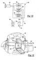
- FIG. 10b another wet/dry vacuum constructed in accordance with the teachings of the present invention is generally indicated by reference numeral 10b.
- the wet/dry vacuum 10b is generally similar to the wet/dry vacuum 10a of Figure 7 except that the powerhead assembly 12b is pivotally (via a hinge 179, for example) attached to a housing 180 that houses the canister assembly 14b.
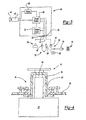
- the controller 46e is illustrated to preferably include a receptacle assembly 64e, a power supply 66e, a power switch 68e and an optional charger circuit 70e.
- the receptacle assembly 64e is electrically coupled to the power supply 66e and configured to conduct electrical power thereto as will be described in detail, below.
- the power supply 66e is electrically coupled to the motor 42e and the power switch 68e to permit the user to selectively enable or disable the flow of electrical power to the motor 42e.
- the electrical cord 24e may include a conventional pronged plug end 74e, which is configured to be electrically coupled to a conventional electrical outlet 76e, and an opposite end (not shown) which is electrically coupled in a conventional manner to the power supply 66e. Accordingly, the electrical cord 24e may permit the user of the wet/dry vacuum 10e to couple the power supply 66e to a source of alternating current (AC) power.
- AC alternating current
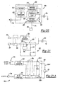
- FIG. 21A an alternately constructed power supply 66e' is illustrated.
- the power supply 66e' differs from the power supply 66e of Figure 21 in that the switch device 630 is associated with the AC/DC converter 600. More specifically, the switch device 630 is illustrated as being a relay 630-1 with first and second contacts 630-2, 630-3, respectively, that are employed to control the flow of electricity.
- the relay 630-1 is illustrated in its normal condition wherein a lead 630-4 from the motor 42e is electrically coupled to the first contact 630-2, which is in turn electrically coupled to the DC/DC converter 602 (via the power switch 68e).
- the relay 630-1 remains in its normal condition unless the AC/DC converter 600 provides power (through the power switch 68e in the example provided) to the relay 630-1.
- the relay 630-1 causes the lead 630-4 from the motor 42e to be electrically coupled to the second contact 630-3, which is in turn electrically coupled to the AC/DC converter 600 (via the power switch 68e).
- the charger circuit 70e may be coupled to the power supply 66e and the receptacle assembly 64e.
- the charger circuit 70e allows for the charging of battery packs having different voltages, as is well known in the art.
- An example of a suitable charger circuit is disclosed in U.S. Patent Nos. 6,427,070 and 6,496,688 .
- a user can charge a battery pack 28e, when the power supply 66e is coupled to a source of alternating current power by placing the battery pack 28e in the receptacle assembly 64e such that the terminals (not shown) of the connector (not shown) of the receptacle assembly 64e electrically engage the associated terminals (not shown) of the battery pack 28e.
- the battery pack 28e may then be employed to power the vacuum 10e or removed from the receptacle assembly 64e and employed to power another device, such as the heavy-duty audio equipment of U.S. Patent No. 6,427,070 or the cordless drill/driver of U.S. Patent No. 6,431,289 .
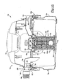
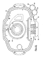
- the canister assembly 14e preferably includes a canister 100e and an over-center cam latching system 102e that employs a pair of over-center cam latches 700 to releasably secure the canister 100e to the powerhead assembly 12e.
- the particular canister 100e illustrated has a capacity of about 7.57 litres (two gallons), but those skilled in the art will appreciate that the canister 100e may in the alternative have a capacity that is larger or smaller.
- the canister assembly 14e also includes a reservoir emptying means 101e that permits a liquid to be emptied from the interior of the canister 100e without removing the powerhead assembly 12e from the canister assembly 12e.
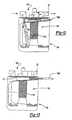
- the filter system 16e may be configured to be carried entirely by the powerhead assembly 12e as is shown in Figure 15.
- the filter system 16e includes a shut-off device 740, a primary filter 114e and an optional secondary filter 116e.
- the secondary filter 116e may be a pad of fibrous material that is coupled to the fan inlet 742, but it could also be made of a mesh or screen material or omitted altogether depending upon the filtering capabilities of the primary filter 114e.
- the secondary filter 116e may be coupled to the power head assembly 12e at a point after (downstream) of the fan 44e.
- the shut-off device 740 is associated with the powerhead assembly 12e and configured to prevent the fan 44e from drawing a liquid into the fan inlet 742 when a volume of liquid in the canister assembly 14e exceeds a predetermined volume.
- the shut-off device 740 may be configured in various ways and may, for example, prevent electrical power from being transmitted to the motor 42e or close-off the fan inlet 742 in response to a volume of liquid in the canister assembly 14e increasing above the predetermined volume.
- the shut-off device 740 includes a plenum 110e and a float 112e.
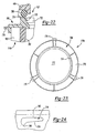
- the lower end cap 764 may be a plate-like structure that is formed from a rigid material and is sealingly bonded to a lower end of the filter body 760. Alternatively, the lower end cap 764 may be wholly or partially formed from the material from which the filter body 760 is manufactured.
- the upper end cap 766 may be an annular flange that is sealingly bonded to an upper end of the filter body 760.
- the upper end cap 766 preferably includes a body 770 that defines a receiving aperture 772, which receives the plenum 110e therethrough when the primary filter 114e is coupled to the powerhead assembly 12e, a seal engagement structure 774, which is illustrated as extending axially from the body 770 and oriented generally concentric with the receiving aperture 772, and a plurality of retaining tabs 776 that are circumferentially spaced about the perimeter of the body 770 and which extend radially outward therefrom.
- the retaining slots 790 may be formed in the inner surface 800 of a collar 802 that extends generally perpendicularly from the bottom surface of the housing 40e concentric to the fan inlet 742.
- Each retaining slot 790 may be generally L-shaped, with a first portion 810, which is configured to axially receive a corresponding one of the retaining tabs 776, and a second portion 812 that extends around a portion of the circumference of the collar 802.
- the second portion 812 includes an engagement surface 814 that is configured to engage the lower surface 794 of a corresponding one of the retaining tabs 776.
- the engagement surface 814 is tapered and includes a notch-like retaining feature 816 that is configured to receive therein the engagement feature 796 of a corresponding one of the retaining tabs 776.
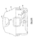
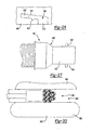
- the terminal end 868 of the retaining portion 866 is somewhat elongated in a direction that is generally parallel to the insertion portion 864 so that when an attachment lug 854 is disposed therein and a force is applied to the hose assembly 18e that tends to withdraw it from the powerhead assembly 12e, the attachment lug 854 is able to move forwardly somewhat.
- the exemplary coupling end 850 illustrated must be further inserted to the port and rotated to effect the uncoupling of the hose assembly 18e from the powerhead assembly 12e. The need to both further insert and rotate the coupling end 850 aids in resisting the uncoupling of the hose assembly 18e from the port at an undesired time.
- the tool retainer 890 includes a pair of cylindrical recesses 900, which are configured to receive therein a crevice tool 20e' and a nozzle 20e", and a C-shaped collar 802 that is configured to frictionally engage (i.e., clamp about the perimeter of) the hose assembly 18e.
- the user may store the hose assembly 18e in a storage position as shown in Figure 28 by inserting the coupling end 850 of the hose assembly 18e to the inlet port 50e, wrapping the hose assembly 18e about a lateral side of the vacuum 10e such that the hose assembly 18e is captured below the battery enclosure 550 and lid 552 and clipping a portion of the hose assembly 18e into the C-shaped collar 802.
- the portion of the hose assembly 18e between the C-Shaped collar 802 and the coupling end 850 i.e., the body of the hose assembly 18e
- the portion of the hose assembly 18e between the C-Shaped collar 802 and the coupling end 850 is in a state of tension (owing to the stretchy nature of the body of the hose assembly 18e) so that the body of the hose assembly 18e is secured to the housing 40 and canister 100e when the hose assembly 18e is placed in the storage position.
- a tool set constructed in accordance with the teachings of the present invention is generally indicated by reference numeral 1000.
- the tool set 1000 includes various power tools 1002 and the above-described utility vacuum 10e, which includes the battery pack 28e.
- Each of the power tools 1002 are of a construction that includes a receptacle assembly 64e with a configuration that is compatible and preferably similar or identical to the receptacle assembly 64e of the utility vacuum 10e to thereby permit the battery pack 28e to be selectively coupled to a given one of the power tools 1002 to transmit electrical power thereto for the operation of the given power tool 1002.
- the battery pack 28e may be selectively coupled to any of the components of the tool set 1000 to thereby power the selected power tool 1002 or the utility vacuum 10e.
- the particular power tools 1002 are illustrated to include a drill driver 1002a, a circular saw 1002b, a reciprocating saw 1002c and a flashlight 1002d, those skilled in the art will appreciate in light of this disclosure that the particular power tool may be of any desired type and may include, for example, hammer drills, jig saws, screw drivers, impact wrenches, rotary hammers, routers, spiral saws, plate joiners, metal working shears, grinders, sanders, buffers, self-leveling rotary lasers, manually-leveled rotary lasers and heavy-duty audio equipment.
Landscapes
- Engineering & Computer Science (AREA)
- Mechanical Engineering (AREA)
- Structures Of Non-Positive Displacement Pumps (AREA)
- Secondary Cells (AREA)
Applications Claiming Priority (3)
| Application Number | Priority Date | Filing Date | Title |
|---|---|---|---|
| US42537102P | 2002-11-12 | 2002-11-12 | |
| US10/640,267 US7653963B2 (en) | 2002-11-12 | 2003-08-13 | AC/DC hand portable wet/dry vacuum having improved portability and convenience |
| EP03025864A EP1419723B1 (de) | 2002-11-12 | 2003-11-11 | Verbesserter, handtragbarer Mehrzweck-Staubsauger geeignet für Gleich- und Wechslestrombetrieb |
Related Parent Applications (1)
| Application Number | Title | Priority Date | Filing Date |
|---|---|---|---|
| EP03025864A Division EP1419723B1 (de) | 2002-11-12 | 2003-11-11 | Verbesserter, handtragbarer Mehrzweck-Staubsauger geeignet für Gleich- und Wechslestrombetrieb |
Publications (2)
| Publication Number | Publication Date |
|---|---|
| EP1785079A2 true EP1785079A2 (de) | 2007-05-16 |
| EP1785079A3 EP1785079A3 (de) | 2007-11-14 |
Family
ID=37946002
Family Applications (1)
| Application Number | Title | Priority Date | Filing Date |
|---|---|---|---|
| EP07102680A Withdrawn EP1785079A3 (de) | 2002-11-12 | 2003-11-11 | Verbesserter handtragbarer Mehrzweck-Staubsauger, geeignet für Gleich- und Wechselstrombetrieb |
Country Status (1)
| Country | Link |
|---|---|
| EP (1) | EP1785079A3 (de) |
Cited By (1)
| Publication number | Priority date | Publication date | Assignee | Title |
|---|---|---|---|---|
| EP3476267A1 (de) * | 2017-10-31 | 2019-05-01 | Panasonic Intellectual Property Management Co., Ltd. | Sammelsystem und kollektor |
Citations (8)
| Publication number | Priority date | Publication date | Assignee | Title |
|---|---|---|---|---|
| US2884185A (en) * | 1956-06-29 | 1959-04-28 | American Lincoln Corp | Suction tank head |
| US4080104A (en) * | 1976-05-14 | 1978-03-21 | Brown Jr Edward C | Wet-dry vacuum apparatus with pump means for discharging liquid therefrom |
| DE3544742A1 (de) * | 1985-12-18 | 1987-06-19 | Fickel Hans Christian Dipl Ing | Unabhaengige handlampe mit selbstaetig regenerierender stromquelle, auch als universelle stromquelle geeignet |
| US5208940A (en) * | 1990-11-01 | 1993-05-11 | London Charles A | Floor dryer and warning device |
| EP0903104A1 (de) * | 1997-09-20 | 1999-03-24 | PROAIR GmbH Gerätebau | Nassreinigungsgerät |
| US6044519A (en) * | 1995-12-07 | 2000-04-04 | Emerson Electric Co. | Portable electric tool vacuum cleaner control |
| US6154919A (en) * | 1999-09-14 | 2000-12-05 | Hetko; Walter | Sawdust collection system |
| US6448732B1 (en) * | 1999-08-10 | 2002-09-10 | Pacific Steamex Cleaning Systems, Inc. | Dual mode portable suction cleaner |
-
2003
- 2003-11-11 EP EP07102680A patent/EP1785079A3/de not_active Withdrawn
Patent Citations (8)
| Publication number | Priority date | Publication date | Assignee | Title |
|---|---|---|---|---|
| US2884185A (en) * | 1956-06-29 | 1959-04-28 | American Lincoln Corp | Suction tank head |
| US4080104A (en) * | 1976-05-14 | 1978-03-21 | Brown Jr Edward C | Wet-dry vacuum apparatus with pump means for discharging liquid therefrom |
| DE3544742A1 (de) * | 1985-12-18 | 1987-06-19 | Fickel Hans Christian Dipl Ing | Unabhaengige handlampe mit selbstaetig regenerierender stromquelle, auch als universelle stromquelle geeignet |
| US5208940A (en) * | 1990-11-01 | 1993-05-11 | London Charles A | Floor dryer and warning device |
| US6044519A (en) * | 1995-12-07 | 2000-04-04 | Emerson Electric Co. | Portable electric tool vacuum cleaner control |
| EP0903104A1 (de) * | 1997-09-20 | 1999-03-24 | PROAIR GmbH Gerätebau | Nassreinigungsgerät |
| US6448732B1 (en) * | 1999-08-10 | 2002-09-10 | Pacific Steamex Cleaning Systems, Inc. | Dual mode portable suction cleaner |
| US6154919A (en) * | 1999-09-14 | 2000-12-05 | Hetko; Walter | Sawdust collection system |
Cited By (1)
| Publication number | Priority date | Publication date | Assignee | Title |
|---|---|---|---|---|
| EP3476267A1 (de) * | 2017-10-31 | 2019-05-01 | Panasonic Intellectual Property Management Co., Ltd. | Sammelsystem und kollektor |
Also Published As
| Publication number | Publication date |
|---|---|
| EP1785079A3 (de) | 2007-11-14 |
Similar Documents
| Publication | Publication Date | Title |
|---|---|---|
| EP1419723B1 (de) | Verbesserter, handtragbarer Mehrzweck-Staubsauger geeignet für Gleich- und Wechslestrombetrieb | |
| EP1731073A2 (de) | Verbesserter, handtragbarer Mehrzweck-Staubsauger geeignet für Gleich- und Wechslestrombetrieb | |
| US7845046B2 (en) | Hand-held cordless vacuum cleaner | |
| US8069529B2 (en) | Handheld vacuum cleaner | |
| AU2003101066B4 (en) | AC/DC hand portable wet/dry vacuum having improved portability and convenience | |
| EP1785079A2 (de) | Verbesserter handtragbarer Mehrzweck-Staubsauger, geeignet für Gleich- und Wechselstrombetrieb | |
| NZ530423A (en) | AC/DC hand portable wet/dry vacuum having improved portability and convenience | |
| CN100577078C (zh) | 有改进的轻便便利性的ac/dc手提湿/干真空吸尘器 |
Legal Events
| Date | Code | Title | Description |
|---|---|---|---|
| PUAI | Public reference made under article 153(3) epc to a published international application that has entered the european phase |
Free format text: ORIGINAL CODE: 0009012 |
|
| 17P | Request for examination filed |
Effective date: 20070220 |
|
| AC | Divisional application: reference to earlier application |
Ref document number: 1419723 Country of ref document: EP Kind code of ref document: P |
|
| AK | Designated contracting states |
Kind code of ref document: A2 Designated state(s): AT BE BG CH CY CZ DE DK EE ES FI FR GB GR HU IE IT LI LU MC NL PT RO SE SI SK TR |
|
| RIC1 | Information provided on ipc code assigned before grant |
Ipc: A47L 5/36 20060101ALI20070723BHEP Ipc: A47L 7/00 20060101ALI20070723BHEP Ipc: A47L 5/14 20060101ALI20070723BHEP Ipc: A47L 9/28 20060101AFI20070723BHEP |
|
| PUAL | Search report despatched |
Free format text: ORIGINAL CODE: 0009013 |
|
| AK | Designated contracting states |
Kind code of ref document: A3 Designated state(s): AT BE BG CH CY CZ DE DK EE ES FI FR GB GR HU IE IT LI LU MC NL PT RO SE SI SK TR |
|
| 17Q | First examination report despatched |
Effective date: 20071221 |
|
| AKX | Designation fees paid |
Designated state(s): AT BE BG CH CY CZ DE DK EE ES FI FR GB GR HU IE IT LI LU MC NL PT RO SE SI SK TR |
|
| STAA | Information on the status of an ep patent application or granted ep patent |
Free format text: STATUS: THE APPLICATION IS DEEMED TO BE WITHDRAWN |
|
| 18D | Application deemed to be withdrawn |
Effective date: 20080624 |