EP1784599B1 - Raccord filete de tuyaux d'acier - Google Patents
Raccord filete de tuyaux d'acier Download PDFInfo
- Publication number
- EP1784599B1 EP1784599B1 EP05781434A EP05781434A EP1784599B1 EP 1784599 B1 EP1784599 B1 EP 1784599B1 EP 05781434 A EP05781434 A EP 05781434A EP 05781434 A EP05781434 A EP 05781434A EP 1784599 B1 EP1784599 B1 EP 1784599B1
- Authority
- EP
- European Patent Office
- Prior art keywords
- thread
- threaded joint
- steel pipe
- flanks
- stabbing
- Prior art date
- Legal status (The legal status is an assumption and is not a legal conclusion. Google has not performed a legal analysis and makes no representation as to the accuracy of the status listed.)
- Not-in-force
Links
- 229910000831 Steel Inorganic materials 0.000 title claims abstract description 38
- 239000010959 steel Substances 0.000 title claims abstract description 38
- 229910052751 metal Inorganic materials 0.000 claims abstract description 55
- 239000002184 metal Substances 0.000 claims abstract description 55
- 230000007423 decrease Effects 0.000 claims description 12
- 238000004519 manufacturing process Methods 0.000 description 28
- 238000005520 cutting process Methods 0.000 description 23
- 238000004458 analytical method Methods 0.000 description 22
- 238000000034 method Methods 0.000 description 22
- 230000006835 compression Effects 0.000 description 20
- 238000007906 compression Methods 0.000 description 20
- 239000003129 oil well Substances 0.000 description 20
- 230000013011 mating Effects 0.000 description 11
- 238000005452 bending Methods 0.000 description 8
- 230000000694 effects Effects 0.000 description 8
- 238000011156 evaluation Methods 0.000 description 8
- 238000012360 testing method Methods 0.000 description 8
- 238000012423 maintenance Methods 0.000 description 7
- 230000009467 reduction Effects 0.000 description 6
- 238000013461 design Methods 0.000 description 5
- 238000009434 installation Methods 0.000 description 5
- 230000008878 coupling Effects 0.000 description 4
- 238000010168 coupling process Methods 0.000 description 4
- 238000005859 coupling reaction Methods 0.000 description 4
- 239000012530 fluid Substances 0.000 description 4
- VNWKTOKETHGBQD-UHFFFAOYSA-N methane Chemical compound C VNWKTOKETHGBQD-UHFFFAOYSA-N 0.000 description 4
- 238000007789 sealing Methods 0.000 description 4
- 230000003247 decreasing effect Effects 0.000 description 3
- 239000000463 material Substances 0.000 description 3
- 239000000203 mixture Substances 0.000 description 3
- 230000008569 process Effects 0.000 description 3
- 238000004088 simulation Methods 0.000 description 3
- 238000009412 basement excavation Methods 0.000 description 2
- 230000008859 change Effects 0.000 description 2
- 230000008602 contraction Effects 0.000 description 2
- 239000010779 crude oil Substances 0.000 description 2
- 230000005489 elastic deformation Effects 0.000 description 2
- 239000007789 gas Substances 0.000 description 2
- 239000003345 natural gas Substances 0.000 description 2
- 239000003921 oil Substances 0.000 description 2
- 230000004044 response Effects 0.000 description 2
- 229910000975 Carbon steel Inorganic materials 0.000 description 1
- 229910000599 Cr alloy Inorganic materials 0.000 description 1
- 238000013459 approach Methods 0.000 description 1
- 230000015572 biosynthetic process Effects 0.000 description 1
- 238000004364 calculation method Methods 0.000 description 1
- 239000010962 carbon steel Substances 0.000 description 1
- 238000006243 chemical reaction Methods 0.000 description 1
- 239000000788 chromium alloy Substances 0.000 description 1
- 239000002131 composite material Substances 0.000 description 1
- 150000001875 compounds Chemical class 0.000 description 1
- 238000009826 distribution Methods 0.000 description 1
- 230000003628 erosive effect Effects 0.000 description 1
- 230000005484 gravity Effects 0.000 description 1
- 238000003780 insertion Methods 0.000 description 1
- 230000037431 insertion Effects 0.000 description 1
- 230000007246 mechanism Effects 0.000 description 1
- 230000035515 penetration Effects 0.000 description 1
- 239000003208 petroleum Substances 0.000 description 1
- 229920000642 polymer Polymers 0.000 description 1
- 238000005096 rolling process Methods 0.000 description 1
- 239000007779 soft material Substances 0.000 description 1
- 239000002689 soil Substances 0.000 description 1
- 239000010935 stainless steel Substances 0.000 description 1
- 229910001256 stainless steel alloy Inorganic materials 0.000 description 1
- 238000003466 welding Methods 0.000 description 1
Images


Classifications
-
- F—MECHANICAL ENGINEERING; LIGHTING; HEATING; WEAPONS; BLASTING
- F16—ENGINEERING ELEMENTS AND UNITS; GENERAL MEASURES FOR PRODUCING AND MAINTAINING EFFECTIVE FUNCTIONING OF MACHINES OR INSTALLATIONS; THERMAL INSULATION IN GENERAL
- F16L—PIPES; JOINTS OR FITTINGS FOR PIPES; SUPPORTS FOR PIPES, CABLES OR PROTECTIVE TUBING; MEANS FOR THERMAL INSULATION IN GENERAL
- F16L15/00—Screw-threaded joints; Forms of screw-threads for such joints
- F16L15/001—Screw-threaded joints; Forms of screw-threads for such joints with conical threads
- F16L15/004—Screw-threaded joints; Forms of screw-threads for such joints with conical threads with axial sealings having at least one plastically deformable sealing surface
-
- E—FIXED CONSTRUCTIONS
- E21—EARTH OR ROCK DRILLING; MINING
- E21B—EARTH OR ROCK DRILLING; OBTAINING OIL, GAS, WATER, SOLUBLE OR MELTABLE MATERIALS OR A SLURRY OF MINERALS FROM WELLS
- E21B17/00—Drilling rods or pipes; Flexible drill strings; Kellies; Drill collars; Sucker rods; Cables; Casings; Tubings
- E21B17/02—Couplings; joints
- E21B17/04—Couplings; joints between rod or the like and bit or between rod and rod or the like
- E21B17/042—Threaded
-
- F—MECHANICAL ENGINEERING; LIGHTING; HEATING; WEAPONS; BLASTING
- F16—ENGINEERING ELEMENTS AND UNITS; GENERAL MEASURES FOR PRODUCING AND MAINTAINING EFFECTIVE FUNCTIONING OF MACHINES OR INSTALLATIONS; THERMAL INSULATION IN GENERAL
- F16L—PIPES; JOINTS OR FITTINGS FOR PIPES; SUPPORTS FOR PIPES, CABLES OR PROTECTIVE TUBING; MEANS FOR THERMAL INSULATION IN GENERAL
- F16L15/00—Screw-threaded joints; Forms of screw-threads for such joints
- F16L15/06—Screw-threaded joints; Forms of screw-threads for such joints characterised by the shape of the screw-thread
Definitions
- This invention relates to a threaded joint for connecting steel pipes such as oil well pipes, riser pipes, and line pipes used in the exploration and production of oil wells and gas wells, and in particular it relates to a threaded joint for steel pipes having excellent resistance to compression and resistance to external pressure, ability to seal against internal pressure and external pressure under a compressive load, and preferably also excellent operability during installation in the field.
- EP1296088 A1 discloses a joint with tapered threads comprising a tapered male thread and a tapered female thread threadingly engaged with each other, the thread shapes of the male and female thread having a constant cross section over the entire length of a complete thread portion,
- Threaded joints are typically used as a means for connecting oil well pipes.
- threaded joints are typically used as a means for connecting oil well pipes.
- Figures 1(a) and 1(b) are a schematic cross sectional view of one example of a premium joint and an enlarged view of a portion thereof.
- a premium joint has tapered threads 12 and 22, a metal seal portion 4, and a torque shoulder portion 5.
- the side on which a tapered male thread 12 is provided is referred to as a pin 11, and the side on which a female thread 22 is provided is referred to as a box 21.
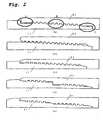
- the metal seal portions and the torque shoulder portions are installed at positions A, B, and C shown in Figure 2(a) , i.e., at position A which is on the outer side of the threads, at position B which is between the threads, and at position C which is inwards of the threads.
- a metal seal portion and a torque shoulder portion are disposed on the inner side of the joint ( Figure 2(b) ), those in which a metal seal portion is disposed on the inner side of the joint and a torque shoulder portion is disposed on the inner side and outer side ( Figure 2(c) ), those in which a metal seal portion is provided on the inner side and outer side and a torque shoulder portion is provided at the middle ( Figure 2(d) ), and those in which a metal seal portion is provided at the middle and on the inner side and a torque shoulder portion is provided on the outer side ( Figure 2(e) ).
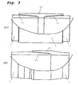
- joints include coupling types (see Figure 3(a) ) in which steel pipes having a pin (a male threaded member) on both ends are connected by a coupling having a box (a female threaded member) provided at both ends of a short pipe, and integral type (see Figure 3(b) ) in which steel pipes having a pin provided on one end and a box provided at the opposite end are directly connected to each other.
- Gas tightness which is one of the important properties of a premium joint, is exhibited by interfitting the metal seal portions with a suitable amount of interference determined by design.
- interference refers to a press fit of the sealing surfaces and it is a value given by (diameter of the metal seal portion of the box) minus (diameter of the metal seal portion of the pin).
- interference is also provided in the tapered thread portions.
- buttress thread there is strong contact at the thread root due to the interference of the thread portions.
- interference is the value given by (diameter of the thread portion of the box) minus (diameter of the thread portion of the pin).
- torque shoulder portions function as stoppers for providing a suitable fit between the metal seal portions.
- a premium joint can exhibit its properties to a maximum extent by abutting the torque shoulder portions within the range of elastic deformation and completing make-up in a state in which a make-up force in the axial direction is generated within the joint.
- FIGs 5(a) and 5(b) schematically explain these states.
- an oil well 33 on the sea bottom is connected by a vertically-descending riser pipes 35 to a rig 34 on the surface of the sea, so a large compressive force acts on the riser pipe.
- oil well pipes 31 extend in the horizontal direction or in which oil well pipes 32 are bent.
- Oil wells typically have a depth from around 3,000 meters to 6,000 meters, and oil well pipes having a length of around 8-10 meters are inserted into a well bore from atop the ground or from atop a rig on the surface of the sea while connected by the above-described threaded joints. Namely, in order to install oil well pipes underground in a single oil well, make-up of threaded joints is carried out approximately 300 to 750 times.
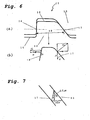
- threads having the object of increasing resistance to compression there is a thread in which the load flanks and the stabbing flanks of a trapezoidal thread are made to contact and gaps are provided at the thread root surface and the thread crest surface (referred to below as a rugged thread).
- Figure 6(a) is a schematic explanatory view of the cross-sectional shape of a rugged thread 22
- Figure 6(b) is an explanatory view showing the distribution of forces thereon.
- make-up is normally controlled based on the torque. Namely, the torque reaction is monitored during make-up, and make-up is completed when a prescribed make-up torque is reached.
- the variation in torque due to thread tolerances is extremely large, so it is difficult to set a suitable make-up torque.
- a suitable torque indicates a make-up torque which can make the shoulders abut within the range of elastic deformation for all products made to manufacturing tolerances.
- the torque at the start of shoulder contact (referred to as the shouldering torque) of a product within tolerances exceeds the torque at which the shoulders undergo plastic deformation (referred to below as overtorque) for another product which is within tolerances, and a suitable torque no longer exists.
- the above-described situation (generally referred to as the high shouldering problem) is unavoidable with present-day manufacturing control techniques (allowable manufacturing tolerances) particularly with respect to small-diameter rugged threads having an outer diameter of 5 inches or less.
- Patent Document 3 With the object of improving the ability to seal against external pressure, in Patent Document 3, for example, a large portion of a pin member is increased in thickness by swaging (reduction of the inner diameter of the pipe end).
- Patent Document 4 the resistance to deformation of the end of a pin is increased as much as possible by providing a male thread as close as possible to the torque shoulder of the end of the pin.
- the resistance to deformation in response to external pressure is increased by increasing the wall thickness of the in member or of the connecting portion between the torque shoulder at the end of the pin and the thread portion to reduce the decrease in diameter, and a gap is prevented from forming at a metal seal.
- Patent Document 3 it is necessary to perform swaging over a considerable length of the pipe end (probably around 100 - 200 mm), so a horizontal rolling mill of extremely large power is required, and the swaging die rapidly deteriorates, so there is concern of manufacturing costs becoming quite high.
- the inner diameter of a joint is reduced by considerable ratio, so turbulence when internal fluids pass through the joint portion becomes severe and there is a concern of its causing erosion.
- the size of pipe which can be inserted into its interior decreases, so the string design ends up being having extremely poor efficiency.
- Patent Document 4 there is the effect that the decrease in the interference of the metal seal portion can be restrained to a certain extent by the amount that the decrease in diameter of the connecting portion between the torque shoulder at the end of the pin and the thread portion is reduced, but compared to the technique in Patent Document 3 in which the thickness of the pin lip is directly increased, its effect is limited.
- Patent Document 5 Prior art with the object of increasing ease of make-up includes Patent Document 5 and Patent Document 6.
- This prior art has the object of increasing make-up speed and stabbing properties.
- Stabbing properties refer to how smoothly insertion can be carried out to a state in which thread engagement is started at the time of inserting the pin of a male threaded member into the box of a female threaded member. The more easily a pin can be stably inserted to the rearmost portion of a box even when there is a large deviation between the axis of the pin and the box or of the angles therebetween, the better are the stabbing properties of a joint.
- Make-up speed is the number of rotations in which a joint can be tightened.
- the above-described prior art aims at improving stabbing properties and make-up speed primarily by employing a multiple-start thread or by adjusting the slope of the thread crest surface or the thread height.
- the object of the present invention is to provide means which can maintain the excellent resistance to compression of a rugged thread and which at the same time can suppress torque variations, which are a problem of rugged threads, to a low level which can be manufactured with current tolerance control techniques, which can guarantee resistance to external pressure, and which can increase operability in the field and particularly make-up speed.
- the present inventors considered from the standpoint of mechanics why a rugged thread has a large variation in torque compared to a buttress thread.
- Equations 1 and 2 the contact forces C 1 to C 4 of each of the thread surfaces can be expressed in terms of the mating force F as follows.
- C 1 Fcos ⁇ / sin ⁇ sin ⁇ + cos ⁇ cos ⁇
- C 2 Fsin ⁇ / sin ⁇ sin ⁇ + cos ⁇ cos ⁇
- C 3 Fcos ⁇ / sin ⁇ cos ⁇ + sin ⁇ cos ⁇
- C 4 Fcos ⁇ / sin ⁇ cos ⁇ + sin ⁇ cos ⁇
- the make-up torque of the threads can be estimated by multiplying the frictional resistance due to the contact forces C 1 to C 4 by the length of the arm R.
- Make - up torque of a buttress thread T B C 1 + C 2 ⁇ ⁇ R
- Make - up torque of a rugged thread T R C 3 + C 4 ⁇ ⁇ R
- the make-up torque T R of a rugged thread is calculated as being 3.3 times the make-up torque T B of a buttress thread.
- the interference ⁇ is nearly proportional to the mating force F, so the torque variation ⁇ T R when the range of manufacturing tolerance of the interference is equal to ⁇ can also be said to be 3.3 times ⁇ T B .
- the present inventors studied the mechanism when a leak of outside pressure occurs in the typical premium joint of Figure 1 , and they studied the requirements of a strong seal against external pressure.
- seal surfaces which are conical surfaces or surfaces formed by rotating a curve, against each other in the radial direction to generate a contact force and product intimate contact between the seal surfaces.
- an external pressure which is nearly the same as that acting on the body of the pipe, acts on the male thread surface up to before the metal seal portion, and to the extent that its wall thickness is less than that of the pipe body, its resistance to shrink deformation (in order to distinguish it from bending stiffness, which will be described below, it will be referred to here as shrink stiffness) is smaller, and the reduction in its diameter increases.
- the seal interference i.e., the seal contact force decreases, and it is thought that leaks develop in the metal seal portion when it falls below a prescribed limit.
- the concept of the present invention was achieved, which is that the ability to seal against external pressure can be further effectively increased by considering the shape of a metal seal portion (lip portion) having a shape which simultaneously realizes methods (ii) and (iii).
- the excellent compression resistance of a rugged thread can be maintained while torque variation, which is a problem of rugged threads, can be restrained to a low level capable of being manufactured with present-day tolerance control techniques, resistance to external pressure can be guaranteed, and operability in the field and particularly make-up speed can be increased.
- the thread of a premium joint is machined with a lathe using a cutting bite, referred to as a chaser, having the thread groove shape of a trapezoidal thread.
- a joint according to the present invention can provide two different threads in the form of a rugged thread and a buttress thread by usual thread cutting using a chaser with a single shape.
- the female thread height of the portion which is to be made into a rugged thread is reduced by cutting or grinding (referred to below as cutting/grinding), the female thread is reduced in the radial direction by the given interference, and a rugged thread is obtained which has contact at the stabbing flanks instead of at the thread root.
- the present inventors developed design equations for prescribing a suitable combination thereof from the following ideas.
- a third mode of the present invention in which the slope of the end portion of only the load flank of the thread which is cut (the female thread in a first mode ( Figure 10(a) ) and the male thread in a second mode ( Figure 10(b) ), or only the stabbing flank, or the end portion of both the load flank and the stabbing flank and preferably the portion on 1/8 - 1/2 of the inner diameter side of the female thread or of the outer diameter side of the male thread is reduced to a value of at least 25° and preferably at least 35 ° and at most 60°.
- Threads according to the above-described first, second, and third modes of the present invention can be applied to a threaded joint with tapered threads of the coupling type or integral type for connecting steel pipes of any size or material.
- they can be applied to any thread dimensions, and the effects thereof can be exhibited.
- the pipe size has an outer diameter from roughly 2-3/8 inches (approximately 60 mm) to 20 inches (approximately 510 mm), and the material is primarily a steel such as carbon steel, stainless steel, or chromium alloy steel having a yield strength from 552 MPa (80 ksi) to 1034 MPa (150 ksi).
- the dimensions which are provided on oil well pipes of the above-mentioned size are primarily a thread pitch of from 2.5 mm to 12.7 mm, a thread height of 0.7 mm to 4 mm, and a thread taper of 1/20 to 1/8.
- the amount c by which the thread height is reduced by cutting/grinding is made greater than necessary, the height of thread engagement decreases, and it becomes easy for jump-out (the phenomenon in which threads become disengaged when tension is applied) to occur, so it is preferably as small as possible within the range satisfying Equation 8.
- a thread according to the present invention can be obtained by, for example, setting the thread pitch to 5.08 mm, the thread taper to 1/18, the height of the male threads to 1.4 mm, the height of the female threads prior to cutting/grinding to 1.6 mm, the load flank angle to 3°, the stabbing flank angle to 35°, the gap a at the thread stabbing flanks to 0.04 mm, the cutting height c to 0.2 mm, and the minimum value of the thread interference (over the diameter) to 0.2 mm.
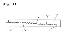
- the thread may be a two-level thread having a metal seal portion 4 disposed at its center. If a different thread shape is provided in each thread portion, such as a rugged thread for the thread at the tip of the pin (referred to below as the first thread portion) and a buttress thread as the thread on the pipe side (referred to below as the second thread portion), the above-described problems of thread cutting are solved, and a joint which is a mixture of a rugged thread and a buttress thread is easily obtained.
- a metal seal portion is provided not at the tip of the pin but between the threads, so a large wall thickness can be provided in the metal seal portion of the pin, and since a tapered thread portion which meshes with the box portion is provided closer to the end of the pin than the metal seal, the bending stiffness of the metal seal portion of the pin becomes extremely large.
- Either a rugged thread or a buttress thread can be provided in the first thread portion or the second thread portion, but from the standpoint of manufacture, it is preferable to provide one type of thread as a continuous thread in each thread portion.
- a metal seal portion is provided in at least one location between the first thread portion and the second thread portion (portion B), but in addition thereto, a second or third metal seal or a sealing ring made of a soft material such as rubber or a polymer or a composite material may be provided closer to the end than the first thread portion (portion C), and/or closer to the pipe (portion A) than the second thread portion (see Figure 2(a) ).
- portion C good sealing properties can be exhibited not only with respect to external pressure but also with respect to internal pressure (see Figure 2(b) ).
- a torque shoulder is preferably provided in portions B and C.
- a torque shoulder is preferably provided in portions A and C.
- a preferred position for installation of a torque shoulder portion in the present invention is the location of portion C.
- a preferred range for the thread load flanks is in the range of -10 to +10° with respect to a plane perpendicular to the joint axis.
- the thread stabbing flank angle of the threads is preferably from +15° to +50°.
- first thread ridge and the second thread ridge can each engage with a corresponding thread groove of the both of the first thread ridge and the second thread ridge.
- either the male thread or the female thread must have exactly the same thread shape and thread dimensions for the first thread ridge and the second thread ridge.
- Figure 12(a) shows the case in which there is not contact at any of the four surfaces of the nonrugged thread
- Figure 12(b) shows the case in which there is contact only at the stabbing flank
- Figure 12(c) shows the case in which there is contact only at the crest surface
- Figure 12(d) shows the case in which there is contact at the thread root surface forward of the load flank of the nonrugged thread
- Figure 12(e) shows the case in which there is contact only at the load flank
- Figure 12(f) shows the case in which there is contact at the thread root to the rear of the stabbing flank of the nonrugged thread
- Figure 12(g) shows the case in which there is contact at the load flank and the thread crest surface
- Figure 12(h) shows the case in which there is contact at the thread crest surface and the stabbing flank
- Figure 12(i) shows the case in which there is contact at the load flank and at the thread root surface to the rear of the stabbing flank
- Figure 12(j) shows the case in which there is contact at the thread
- angles of the sloping surfaces are of course the same for the rugged thread and the nonrugged thread.
- another mode of the present invention may be a multiple-start thread having more than two thread ridges.
- the number of threads of the rugged thread is given by 1 ⁇ n ⁇ (number of thread ridges/2).
- the subject of evaluation was the coupling-type threaded joint for oil well pipes shown in Figure 1 . It was a joint for a 5-1/2 inch #20 pipes (outer diameter of 139.7 mm, wall thickness of 9.17 mm) joint.
- the material was that having the API specification P110. In finite element analysis, it was treated as an elasto-plastic body with an isotropic hardness, and it was numerically modeled as having a coefficient of elasticity of 210000 MPa and having a 0.2% strength equal to the nominal yield strength of 110 ksi (758 MPa).
- Table 1 shows the joints on which evaluation was carried out.
- the shapes of the metal seal portions and the torque shoulder portions being analyzed were slightly different from each other, but the minimum values and the maximum values of the seal interference were all the same.
- Thread cutting test was carried out only on Samples 2 and 3. Thread cutting was carried out on 10 pipes, and the number of test pipes on which burrs requiring removal were formed (having a height of approximately 0.15 mm or higher) was recorded.
- Example 1 was repeated, and numerical simulation analysis by the elasto-plastic finite element method was carried out.
- Sample 6 which was a j oint according to the present invention had a rugged thread as a first thread portion of a two-level thread and a buttress thread as a second thread portion.
- a metal seal was disposed only in portion B, and a torque shoulder was disposed only in portion C.
- Samples 7-8 were one-level threads like that shown in Figure 1 . They had a structure in which a metal seal and a torque shoulder were provided at the end portion of a pin.
- Samples 6-8 each had a thread pitch of 5.08 mm and a thread taper of 1/18.
- Table 3 Sample No. Manufacturing tolerance of thread interference (over diameter) Load flank angle Stabbing flank angle Stabbing flank gap No. of rugged threads/total number of threads Comments 6 0.2 mm +3° 35° 0.09 mm for buttress thread portion, 0.00 mm for rugged thread portion 8/17 Threads of present invention 7 0.2 mm +3° 35° 0.00 mm 15/15 All rugged threads 8 0.19 mm -3° 10° 0.09 mm 0/15 All buttress threads
- Table 4 shows the results of evaluation. From these results, it can be seen that the joint according to the present invention of Sample 6 had a much smaller torque variation than the joint of Sample 7 having all rugged threads, the reduction in torque after release of compression was much better compared to the buttress thread of the joint of Sample 8, and the contact force maintaining rate in the metal seal portion under an external pressure was also good.
- a thread according to the present invention is greatly improved with respect to torque variation compared to a rugged thread, it maintains excellent resistance to compression, and it also has excellent ability to seal against external pressure.
- Example 1 was repeated, and numerical simulation analysis by the elasto-plastic finite element method and estimation of the time for thread make-up were carried out.
- Table 5 shows the joint on which evaluation was carried out.
- Ones shown in Figure 12 were used as representative examples of the present invention.
- the shapes of the metal seal portion and the torque shoulder portion being analyzed had slight differences, but the minimum and the maximum values of the seal interference were the same for each.
- thread make-up was analyzed with respect to the joints of Table 5 for the combination of interference providing the largest generated torque and the combination providing the smallest generated torque, and the variation in shouldering torque was evaluated.
- a two-start thread according to the present invention can shorten the time by approximately 20%.
- make-up is considered as being divided into the three stages of (i) stabbing (the process of vertically inserting a pin member into a box member) and hand tightening (the operator performs rotation by hand until a position at which rotation stops), (ii) machine tightening (the process of tightening to a prescribed torque by a machine such as power tongs) and (iii) adjustment after make-up, with the single-start thread, the time required was roughly (i) two minutes, (ii) two minutes, and (iii) one minute, but by employing a two-start thread according to the present invention, the time required for (ii) can be reduced by half.
- a thread according to the present invention is improved with respect to torque variation compared to a rugged thread, it maintains excellent resistance to compression, and the time required for thread make-up is greatly reduced.
Landscapes
- Engineering & Computer Science (AREA)
- General Engineering & Computer Science (AREA)
- Mechanical Engineering (AREA)
- Mining & Mineral Resources (AREA)
- Life Sciences & Earth Sciences (AREA)
- Geology (AREA)
- Fluid Mechanics (AREA)
- Environmental & Geological Engineering (AREA)
- Physics & Mathematics (AREA)
- General Life Sciences & Earth Sciences (AREA)
- Geochemistry & Mineralogy (AREA)
- Non-Disconnectible Joints And Screw-Threaded Joints (AREA)
- Earth Drilling (AREA)
Abstract
Claims (13)
- Raccord fileté pour un tuyau en acier comportant un élément d'extrémité mâle (11) ayant un filet mâle conique (12), une partie (4) formant un joint métallique et une partie (5) formant un épaulement de couple, et comportant un élément de boîte (21) ayant un filet femelle conique (22), une partie formant un joint métallique et une partie formant un épaulement de couple, ces parties correspondant à celles de la partie de l'extrémité mâle,
caractérisé en ce que les filets qui constituent le filet mâle conique (12) et le filet femelle conique (22) ont une première partie de filet trapézoïdal qui n'a pas de contact simultané au niveau des flancs de charge (16) et des flancs de guidage (17), et une seconde partie de filet trapézoïdal qui a un contact au niveau des flancs de charge (16) et des flancs de guidage (17) et qui comporte des intervalles au niveau des surfaces de fond de filet (14) et des surfaces de sommet de filet (18),
dans lequel la première partie du filet trapézoïdal a un contact au niveau des flancs de charge (16) et au niveau de la surface de fond de filet (14), et des intervalles au niveau de la surface de sommet de filet (18) et des flancs de guidage (17). - Joint fileté pour un tuyau en acier selon la revendication 1, caractérisé en ce que l'angle (α) du flanc de charge, par rapport à une surface perpendiculaire à l'axe du tuyau, est au moins de -10° et au plus de +10°, et l'angle (θ) du flanc de guidage est au moins de +15° et au plus de +50°.
- Joint fileté pour un tuyau en acier selon l'une des revendications 1 ou 2, caractérisé en ce que l'intervalle "a" dans la direction axiale, au niveau des flancs de guidage de la première partie du filet trapézoïdal, répond à l'équation suivante :

dans laquelle α est l'angle du flanc de charge, Θ est l'angle du flanc de guidage et δ est l'interférence du filet (par rapport au diamètre). - Joint fileté pour un tuyau en acier selon l'une quelconque des revendications 1 à 3, caractérisé en ce que l'angle α du flanc de charge, sur une partie allant de 1/8 à 1/2 du côté du diamètre intérieur des flancs de charge (16) du filet femelle (22), est au moins de 25° et au plus de 60° par rapport à une surface perpendiculaire à l'axe du tuyau.
- Joint fileté pour un tuyau en acier selon l'une quelconque des revendications 1 à 4, caractérisé en ce que l'angle Θ du flanc de guidage, sur une partie allant de 1/8 à 1/2 du côté du diamètre intérieur des flancs de guidage (17) du filet femelle (22), est au moins de 25° et au plus de 60° par rapport à une surface perpendiculaire à l'axe du tuyau.
- Joint fileté pour un tuyau en acier selon l'une quelconque des revendications 1 à 5, caractérisé en ce que l'angle α du flanc de charge, sur une partie allant de 1/8 à 1/2 du côté du diamètre extérieur des flancs de charge (16) du filet mâle (12), est au moins de 25° et au plus de 60° par rapport à une surface perpendiculaire à l'axe du tuyau.
- Joint fileté pour un tuyau en acier selon l'une quelconque des revendications 1 à 6, caractérisé en ce que l'angle Θ du flanc de guidage, sur une partie allant de 1/8 à 1/2 du côté du diamètre extérieur des flancs de guidage (17) du filet mâle (12), est au moins de 25° et au plus de 60° par rapport à une surface perpendiculaire à l'axe du tuyau.
- Joint fileté pour un tuyau en acier selon l'une quelconque des revendications 1 à 7, caractérisé en ce que la seconde partie du filet trapézoïdal a une partie de filet incomplet sur le filet mâle conique (12).
- Joint fileté pour un tuyau en acier selon la revendication 3, caractérisé en ce que la seconde partie du filet trapézoïdal a une partie de filet incomplet sur le filet mâle conique (12), et l'importance de la diminution "c" (par rapport au rayon) de la hauteur du filet mâle (12), dans la partie de filet incomplet du filet mâle conique (12), répond à l'équation suivants :

- Joint fileté pour un tuyau en acier selon l'une quelconque des revendications 1 à 9, ayant une partie (4) formant un joint métallique entre la première partie du filet trapézoïdal et la seconde partie du filet trapézoïdal.
- Joint fileté pour un tuyau en acier selon la revendication 10, caractérisé en ce qu'une autre partie (4) formant un joint métallique est prévue en plus de la partie (4) formant un joint métallique, décrite ci-dessus.
- Joint fileté pour un tuyau en acier selon l'une quelconque des revendications 1 à 11, dans lequel le filetage est un filetage à filets multiples.
- Joint fileté pour un tuyau en acier selon la revendication 12, caractérisé en ce que l'un ou l'autre du filet mâle (12) et du filet femelle (22) a des dimensions et une forme de filetage qui sont les mêmes pour chaque sillon du filetage.
Priority Applications (1)
| Application Number | Priority Date | Filing Date | Title |
|---|---|---|---|
| PL05781434T PL1784599T3 (pl) | 2004-08-27 | 2005-08-24 | Gwintowane złącze do rur stalowych |
Applications Claiming Priority (2)
| Application Number | Priority Date | Filing Date | Title |
|---|---|---|---|
| JP2004248359A JP2007205361A (ja) | 2004-08-27 | 2004-08-27 | 鋼管用ねじ継手 |
| PCT/JP2005/015828 WO2006022418A1 (fr) | 2004-08-27 | 2005-08-24 | Raccord filete de tuyaux d'acier |
Publications (3)
| Publication Number | Publication Date |
|---|---|
| EP1784599A1 EP1784599A1 (fr) | 2007-05-16 |
| EP1784599A4 EP1784599A4 (fr) | 2010-08-04 |
| EP1784599B1 true EP1784599B1 (fr) | 2012-05-30 |
Family
ID=35967613
Family Applications (1)
| Application Number | Title | Priority Date | Filing Date |
|---|---|---|---|
| EP05781434A Not-in-force EP1784599B1 (fr) | 2004-08-27 | 2005-08-24 | Raccord filete de tuyaux d'acier |
Country Status (12)
| Country | Link |
|---|---|
| US (1) | US7494159B2 (fr) |
| EP (1) | EP1784599B1 (fr) |
| JP (2) | JP2007205361A (fr) |
| CN (1) | CN100529498C (fr) |
| AR (1) | AR050381A1 (fr) |
| BR (1) | BRPI0514997B1 (fr) |
| CA (1) | CA2578008C (fr) |
| ES (1) | ES2387558T3 (fr) |
| MX (1) | MX2007002353A (fr) |
| PL (1) | PL1784599T3 (fr) |
| RU (1) | RU2335686C1 (fr) |
| WO (1) | WO2006022418A1 (fr) |
Families Citing this family (59)
| Publication number | Priority date | Publication date | Assignee | Title |
|---|---|---|---|---|
| ATE487021T1 (de) * | 2006-01-20 | 2010-11-15 | Exxonmobil Upstream Res Co | Verfahren und system zur evaluierung von gruppen von in threads vorliegenden verbindungen |
| EP2002165B1 (fr) * | 2006-03-31 | 2017-09-06 | Nippon Steel & Sumitomo Metal Corporation | Joint tubulaire filete |
| US7537145B2 (en) | 2007-02-01 | 2009-05-26 | Black & Decker Inc. | Multistage solenoid fastening device |
| JP5250990B2 (ja) * | 2007-03-28 | 2013-07-31 | 新日鐵住金株式会社 | 油井管用ねじ継手 |
| JP5178034B2 (ja) * | 2007-03-28 | 2013-04-10 | 新日鐵住金株式会社 | 油井管端部へのねじの切削加工方法 |
| FR2917805B1 (fr) * | 2007-06-25 | 2009-09-04 | Vallourec Mannesmann Oil & Gas | Element filete de composant a filetage antagonistes, et joint filete tubulaire correspondant |
| RU2457313C1 (ru) * | 2008-05-04 | 2012-07-27 | Акватик Компани | Алюминиевая компоновка райзера |
| FR2940677B1 (fr) * | 2008-12-29 | 2016-07-22 | Vallourec Mannesmann Oil & Gas France | Joint tubulaire etanche utilise dans l'industrie du petrole |
| FR2944553B1 (fr) * | 2009-04-17 | 2011-06-03 | Vallourec Mannesmann Oil & Gas | Composant tubulaire pour le forage et l'exploitation des puits d'hydrocarbures et joint filete resultant |
| US8167340B2 (en) * | 2009-11-18 | 2012-05-01 | Hunting Energy Services, Inc. | Drill stem tubular connection with internal stiffener ring |
| JP5371007B2 (ja) * | 2009-11-19 | 2013-12-18 | 新日鐵住金株式会社 | 油井管用のねじ継手 |
| FR2952993B1 (fr) | 2009-11-20 | 2011-12-16 | Vallourec Mannesmann Oil & Gas | Joint filete |
| FR2953272B1 (fr) * | 2009-11-30 | 2011-12-16 | Vallourec Mannesmann Oil & Gas | Joint filete |
| FR2954453B1 (fr) * | 2009-12-23 | 2012-03-09 | Vallourec Mannesmann Oil & Gas | Ensemble pour la realisation d'un joint filete, procede de vissage et de devissage d'un tel joint et utilisation d'un tel joint dans une colonne montante sous-marine |
| US20110180273A1 (en) | 2010-01-28 | 2011-07-28 | Sunstone Technologies, Llc | Tapered Spline Connection for Drill Pipe, Casing, and Tubing |
| US20150176341A1 (en) | 2010-01-28 | 2015-06-25 | Sunstone Technologies, Llc | Tapered Spline Connection for Drill Pipe, Casing, and Tubing |
| EP2568112B1 (fr) * | 2010-05-06 | 2019-01-23 | Nippon Steel & Sumitomo Metal Corporation | Appareil d'essai pour un raccord fileté pour produits tubulaires pour puits de pétrole |
| FR2961576B1 (fr) * | 2010-06-17 | 2012-08-03 | Vallourec Mannesmann Oil & Gas | Joint filete et procede de realisation |
| JP4930647B1 (ja) * | 2010-06-30 | 2012-05-16 | Jfeスチール株式会社 | 管用ねじ継手 |
| MX2013000387A (es) | 2010-07-02 | 2013-03-22 | Sunstone Technologies Llc | Cableado electrico para varilla de perforacion, revestimiento y tuberia. |
| CN101881139B (zh) * | 2010-07-07 | 2015-07-08 | 天津天钢石油专用管制造有限公司 | 石油天然气工业用管螺纹接头 |
| US8714600B2 (en) * | 2010-07-22 | 2014-05-06 | Vladimir Petrovich Aldohin | Highly-tight threaded joint |
| EP2420646A1 (fr) | 2010-08-16 | 2012-02-22 | TPS-Technitube Röhrenwerke GmbH | Raccord de tuyauterie |
| JP5849749B2 (ja) * | 2011-02-28 | 2016-02-03 | Jfeスチール株式会社 | 管用ねじ継手 |
| JP5923911B2 (ja) * | 2011-03-22 | 2016-05-25 | Jfeスチール株式会社 | 鋼管用ねじ継手 |
| JP5891700B2 (ja) * | 2011-10-17 | 2016-03-23 | Jfeスチール株式会社 | 管のねじ継手 |
| CN102322227A (zh) * | 2011-10-24 | 2012-01-18 | 大庆福斯特科技开发有限公司 | 一种8tpi螺纹齿形结构 |
| CN102678071A (zh) * | 2012-06-06 | 2012-09-19 | 无锡西姆莱斯石油专用管制造有限公司 | 高密封特殊偏梯形螺纹套管连接接头 |
| RU2500875C1 (ru) | 2012-07-20 | 2013-12-10 | Общество С Ограниченной Ответственностью "Тмк-Премиум Сервис" | Высокогерметичное резьбовое соединение насосно-компрессорных труб (варианты) |
| CN104583662B (zh) * | 2012-09-21 | 2016-08-24 | 新日铁住金株式会社 | 钢管用螺纹接头 |
| US9869139B2 (en) | 2012-11-28 | 2018-01-16 | Ultra Premium Oilfield Services, Ltd. | Tubular connection with helically extending torque shoulder |
| US9677346B2 (en) | 2012-11-28 | 2017-06-13 | Ultra Premium Oilfield Services, Ltd. | Tubular connection with helically extending torque shoulder |
| RU2504710C1 (ru) * | 2012-12-13 | 2014-01-20 | Общество С Ограниченной Ответственностью "Тмк-Премиум Сервис" | Высокогерметичное резьбовое соединение обсадных труб (варианты) |
| EP3043098B1 (fr) | 2013-09-06 | 2023-04-26 | Nippon Steel Corporation | Connexion fileté pour tuyau en acier |
| US9695649B2 (en) * | 2013-10-03 | 2017-07-04 | Nabors Industries, Inc. | Interlock pipe connection |
| CN103556956B (zh) * | 2013-11-01 | 2015-11-25 | 南通永大管业股份有限公司 | 一种高密封性油管的自适应螺纹结构 |
| CN105683487B (zh) * | 2013-12-27 | 2018-03-27 | 哈里伯顿能源服务公司 | 具有高弯曲和转矩容量的螺纹连接 |
| CN105899864B (zh) | 2014-01-09 | 2017-07-25 | 新日铁住金株式会社 | 钢管用螺纹接头 |
| US10281066B2 (en) * | 2014-03-07 | 2019-05-07 | Houston International Specialty, Inc. | Flush threaded connection and method of forming and using the flush threaded connection |
| US10041307B2 (en) | 2015-01-22 | 2018-08-07 | National Oilwell Varco, L.P. | Balanced thread form, tubulars employing the same, and methods relating thereto |
| RU2661917C1 (ru) | 2015-03-30 | 2018-07-23 | ДжФЕ СТИЛ КОРПОРЕЙШН | Трубное резьбовое соединение |
| UA122422C2 (uk) | 2015-10-21 | 2020-11-10 | Ніппон Стіл & Сумітомо Метал Корпорейшн | Нарізне з’єднання для сталевої труби |
| US9683684B1 (en) | 2015-12-09 | 2017-06-20 | Certus Energy Solutions, Llc | Tubular coupling |
| US11466800B2 (en) | 2015-12-09 | 2022-10-11 | Certus Energy Solutions, Llc | Tubular coupling |
| US11493154B2 (en) * | 2015-12-11 | 2022-11-08 | Vallourec Oil And Gas France | Threaded connection including an intermediate shoulder |
| UA119127C2 (uk) * | 2015-12-15 | 2019-04-25 | Ніппон Стіл Енд Сумітомо Метал Корпорейшн | Нарізне з'єднання для сталевої труби |
| RU2694698C1 (ru) * | 2016-01-25 | 2019-07-16 | Ниппон Стил Энд Сумитомо Метал Корпорейшн | Резьбовое соединение для стальной трубы |
| RU2669018C2 (ru) * | 2016-04-28 | 2018-10-05 | Юрий Николаевич Антипов | Замок для бурильной трубы и способ его производства |
| EP3449139B1 (fr) | 2016-04-29 | 2023-01-11 | Infastech Intellectual Properties Pte. Ltd. | Forme de filet anti-vibration |
| WO2017213048A1 (fr) * | 2016-06-08 | 2017-12-14 | 新日鐵住金株式会社 | Raccord à vis destiné à un tuyau en acier |
| CN107288553A (zh) * | 2017-07-24 | 2017-10-24 | 延安守山机械制造有限公司 | 一种偏梯形螺纹 |
| AR113535A1 (es) | 2017-12-05 | 2020-05-13 | Nippon Steel & Sumitomo Metal Corp | Unión roscada para tubos de acero |
| PL3572613T3 (pl) * | 2018-05-25 | 2021-05-04 | Vallourec Oil And Gas France | Rurowe połączenie gwintowane do okładzin |
| JP2020085001A (ja) * | 2018-11-15 | 2020-06-04 | 日本製鉄株式会社 | テーパねじ継手 |
| JPWO2020183860A1 (ja) * | 2019-03-14 | 2021-03-18 | Jfeスチール株式会社 | ねじ継手 |
| CN109958398B (zh) * | 2019-04-26 | 2024-05-07 | 昆山艾蓓蓓阀门有限公司 | 一种应用于油井的四通套管密封结构 |
| CN114320175B (zh) * | 2020-09-29 | 2024-05-14 | 宝山钢铁股份有限公司 | 一种抗粘扣的快速上扣螺纹接头 |
| CN114320189A (zh) * | 2020-09-29 | 2022-04-12 | 宝山钢铁股份有限公司 | 一种螺纹管接头的拧接控制方法 |
| EP3992418B1 (fr) * | 2020-10-28 | 2023-08-02 | Vallourec Oil And Gas France | Connexion filetée autobloquante partiellement dans un enclenchement sans blocage |
Family Cites Families (18)
| Publication number | Priority date | Publication date | Assignee | Title |
|---|---|---|---|---|
| US1927656A (en) * | 1931-12-23 | 1933-09-19 | Spang Chalfant & Co Inc | Pipe joint |
| US2204754A (en) * | 1938-12-29 | 1940-06-18 | Nat Supply Co | Threaded joint |
| US4508375A (en) * | 1982-09-20 | 1985-04-02 | Lone Star Steel Company | Tubular connection |
| JPH0280886A (ja) * | 1988-09-14 | 1990-03-20 | Nippon Steel Corp | シール面圧保持機能の優れた油井管用ネジ継手 |
| JP2705505B2 (ja) * | 1993-03-24 | 1998-01-28 | 住友金属工業株式会社 | 油井管用ねじ継手 |
| DE4431377C1 (de) * | 1994-08-29 | 1996-05-09 | Mannesmann Ag | Rohrverbinder |
| CA2163282C (fr) * | 1994-11-22 | 2002-08-13 | Miyuki Yamamoto | Joint filete pour canalisations de puits de petrole |
| US5749605A (en) * | 1996-03-18 | 1998-05-12 | Protechnics International, Inc. | Electrically insulative threaded connection |
| JP3756652B2 (ja) | 1998-01-08 | 2006-03-15 | 新日本製鐵株式会社 | 管継手 |
| JP3869565B2 (ja) | 1997-12-04 | 2007-01-17 | 新日本製鐵株式会社 | 管継手 |
| JP3700108B2 (ja) | 1998-04-13 | 2005-09-28 | 株式会社メタルワン | 油井管用ネジ継手 |
| FR2807138B1 (fr) * | 2000-03-31 | 2002-05-17 | Vallourec Mannesmann Oil & Gas | Element filete tubulaire pour joint filete tubulaire resistant a la fatigue et joint filete tubulaire resultant |
| JP2001317668A (ja) | 2000-05-02 | 2001-11-16 | Nippon Steel Corp | 耐外圧性能の優れた油井管継手 |
| BR0111528A (pt) * | 2000-06-07 | 2003-07-22 | Sumitomo Metal Ind | Junta com roscas de perfil cÈnico |
| JP3714199B2 (ja) * | 2000-06-07 | 2005-11-09 | 住友金属工業株式会社 | テーパねじ継手 |
| JP2002022070A (ja) | 2000-07-07 | 2002-01-23 | Nippon Steel Corp | 耐外圧性能の優れた油井管ネジ継手 |
| FR2820806B1 (fr) * | 2001-02-09 | 2004-02-20 | Vallourec Mannesmann Oil & Gas | Joint filete tubulaire avec face de filet bombee convexe |
| FR2833335B1 (fr) * | 2001-12-07 | 2007-05-18 | Vallourec Mannesmann Oil & Gas | Joint filete tubulaire superieur contenant au moins un element filete avec levre d'extremite |
-
2004
- 2004-08-27 JP JP2004248359A patent/JP2007205361A/ja active Pending
-
2005
- 2005-08-24 MX MX2007002353A patent/MX2007002353A/es active IP Right Grant
- 2005-08-24 BR BRPI0514997-5A patent/BRPI0514997B1/pt not_active IP Right Cessation
- 2005-08-24 JP JP2007509801A patent/JP4492699B2/ja active Active
- 2005-08-24 CN CNB2005800288520A patent/CN100529498C/zh not_active Expired - Fee Related
- 2005-08-24 EP EP05781434A patent/EP1784599B1/fr not_active Not-in-force
- 2005-08-24 PL PL05781434T patent/PL1784599T3/pl unknown
- 2005-08-24 CA CA2578008A patent/CA2578008C/fr not_active Expired - Fee Related
- 2005-08-24 RU RU2007111124/06A patent/RU2335686C1/ru active
- 2005-08-24 WO PCT/JP2005/015828 patent/WO2006022418A1/fr active Application Filing
- 2005-08-24 ES ES05781434T patent/ES2387558T3/es active Active
- 2005-08-26 AR ARP050103580A patent/AR050381A1/es active IP Right Grant
-
2007
- 2007-02-23 US US11/710,060 patent/US7494159B2/en active Active
Also Published As
| Publication number | Publication date |
|---|---|
| RU2335686C1 (ru) | 2008-10-10 |
| US20070236015A1 (en) | 2007-10-11 |
| CN100529498C (zh) | 2009-08-19 |
| PL1784599T3 (pl) | 2013-01-31 |
| MX2007002353A (es) | 2007-05-08 |
| CA2578008C (fr) | 2010-12-07 |
| WO2006022418A1 (fr) | 2006-03-02 |
| BRPI0514997B1 (pt) | 2018-03-13 |
| BRPI0514997A (pt) | 2008-07-01 |
| JP2007205361A (ja) | 2007-08-16 |
| AR050381A1 (es) | 2006-10-18 |
| JP2008516155A (ja) | 2008-05-15 |
| CN101010536A (zh) | 2007-08-01 |
| ES2387558T3 (es) | 2012-09-26 |
| EP1784599A1 (fr) | 2007-05-16 |
| CA2578008A1 (fr) | 2006-03-02 |
| EP1784599A4 (fr) | 2010-08-04 |
| JP4492699B2 (ja) | 2010-06-30 |
| US7494159B2 (en) | 2009-02-24 |
Similar Documents
| Publication | Publication Date | Title |
|---|---|---|
| EP1784599B1 (fr) | Raccord filete de tuyaux d'acier | |
| EP2002165B1 (fr) | Joint tubulaire filete | |
| EP1631762B1 (fr) | Joint filete pour tuyaux en acier | |
| US6848724B2 (en) | Thread design for uniform distribution of makeup forces | |
| EP3392543B1 (fr) | Joint fileté pour tube en acier | |
| US7513534B2 (en) | Fatigue-resistant threaded component for a tubular threaded joint | |
| EP3064818B1 (fr) | Raccord avec filetage pour tubes de puits de pétrole à parois épaisses | |
| US11795981B2 (en) | Threaded and coupled tubular goods connection | |
| EP3992418B1 (fr) | Connexion filetée autobloquante partiellement dans un enclenchement sans blocage | |
| EP1371892A1 (fr) | Procede de fabrication d'un raccord filete destine a un tuyau de puits de petrole | |
| US20230146768A1 (en) | Threaded connection for steel pipe | |
| CN114945731A (zh) | 带有能抵抗升高扭矩的外肩部的部分自锁定接合的螺纹连接件 | |
| US20170204683A1 (en) | Low break out safety joint and method for releasably connecting a tubing expansion assembly to a drill string |
Legal Events
| Date | Code | Title | Description |
|---|---|---|---|
| PUAI | Public reference made under article 153(3) epc to a published international application that has entered the european phase |
Free format text: ORIGINAL CODE: 0009012 |
|
| 17P | Request for examination filed |
Effective date: 20070221 |
|
| AK | Designated contracting states |
Kind code of ref document: A1 Designated state(s): AT BE BG CH CY CZ DE DK EE ES FI FR GB GR HU IE IS IT LI LT LU LV MC NL PL PT RO SE SI SK TR |
|
| DAX | Request for extension of the european patent (deleted) | ||
| A4 | Supplementary search report drawn up and despatched |
Effective date: 20100701 |
|
| REG | Reference to a national code |
Ref country code: DE Ref legal event code: R079 Ref document number: 602005034444 Country of ref document: DE Free format text: PREVIOUS MAIN CLASS: F16L0015040000 Ipc: F16B0033020000 |
|
| GRAP | Despatch of communication of intention to grant a patent |
Free format text: ORIGINAL CODE: EPIDOSNIGR1 |
|
| RIC1 | Information provided on ipc code assigned before grant |
Ipc: E21B 17/042 20060101ALI20111028BHEP Ipc: F16L 15/04 20060101ALI20111028BHEP Ipc: F16B 33/02 20060101AFI20111028BHEP Ipc: F16L 15/00 20060101ALI20111028BHEP |
|
| GRAS | Grant fee paid |
Free format text: ORIGINAL CODE: EPIDOSNIGR3 |
|
| GRAA | (expected) grant |
Free format text: ORIGINAL CODE: 0009210 |
|
| AK | Designated contracting states |
Kind code of ref document: B1 Designated state(s): AT BE BG CH CY CZ DE DK EE ES FI FR GB GR HU IE IS IT LI LT LU LV MC NL PL PT RO SE SI SK TR |
|
| REG | Reference to a national code |
Ref country code: GB Ref legal event code: FG4D |
|
| REG | Reference to a national code |
Ref country code: CH Ref legal event code: EP |
|
| REG | Reference to a national code |
Ref country code: AT Ref legal event code: REF Ref document number: 560204 Country of ref document: AT Kind code of ref document: T Effective date: 20120615 |
|
| REG | Reference to a national code |
Ref country code: IE Ref legal event code: FG4D |
|
| REG | Reference to a national code |
Ref country code: DE Ref legal event code: R096 Ref document number: 602005034444 Country of ref document: DE Effective date: 20120802 |
|
| REG | Reference to a national code |
Ref country code: RO Ref legal event code: EPE |
|
| REG | Reference to a national code |
Ref country code: NL Ref legal event code: VDEP Effective date: 20120530 |
|
| REG | Reference to a national code |
Ref country code: ES Ref legal event code: FG2A Ref document number: 2387558 Country of ref document: ES Kind code of ref document: T3 Effective date: 20120926 |
|
| REG | Reference to a national code |
Ref country code: LT Ref legal event code: MG4D Effective date: 20120530 |
|
| PG25 | Lapsed in a contracting state [announced via postgrant information from national office to epo] |
Ref country code: CY Free format text: LAPSE BECAUSE OF FAILURE TO SUBMIT A TRANSLATION OF THE DESCRIPTION OR TO PAY THE FEE WITHIN THE PRESCRIBED TIME-LIMIT Effective date: 20120530 Ref country code: SE Free format text: LAPSE BECAUSE OF FAILURE TO SUBMIT A TRANSLATION OF THE DESCRIPTION OR TO PAY THE FEE WITHIN THE PRESCRIBED TIME-LIMIT Effective date: 20120530 Ref country code: FI Free format text: LAPSE BECAUSE OF FAILURE TO SUBMIT A TRANSLATION OF THE DESCRIPTION OR TO PAY THE FEE WITHIN THE PRESCRIBED TIME-LIMIT Effective date: 20120530 Ref country code: LT Free format text: LAPSE BECAUSE OF FAILURE TO SUBMIT A TRANSLATION OF THE DESCRIPTION OR TO PAY THE FEE WITHIN THE PRESCRIBED TIME-LIMIT Effective date: 20120530 Ref country code: IS Free format text: LAPSE BECAUSE OF FAILURE TO SUBMIT A TRANSLATION OF THE DESCRIPTION OR TO PAY THE FEE WITHIN THE PRESCRIBED TIME-LIMIT Effective date: 20120930 |
|
| PG25 | Lapsed in a contracting state [announced via postgrant information from national office to epo] |
Ref country code: LV Free format text: LAPSE BECAUSE OF FAILURE TO SUBMIT A TRANSLATION OF THE DESCRIPTION OR TO PAY THE FEE WITHIN THE PRESCRIBED TIME-LIMIT Effective date: 20120530 Ref country code: GR Free format text: LAPSE BECAUSE OF FAILURE TO SUBMIT A TRANSLATION OF THE DESCRIPTION OR TO PAY THE FEE WITHIN THE PRESCRIBED TIME-LIMIT Effective date: 20120831 Ref country code: SI Free format text: LAPSE BECAUSE OF FAILURE TO SUBMIT A TRANSLATION OF THE DESCRIPTION OR TO PAY THE FEE WITHIN THE PRESCRIBED TIME-LIMIT Effective date: 20120530 |
|
| PG25 | Lapsed in a contracting state [announced via postgrant information from national office to epo] |
Ref country code: BE Free format text: LAPSE BECAUSE OF FAILURE TO SUBMIT A TRANSLATION OF THE DESCRIPTION OR TO PAY THE FEE WITHIN THE PRESCRIBED TIME-LIMIT Effective date: 20120530 |
|
| RAP2 | Party data changed (patent owner data changed or rights of a patent transferred) |
Owner name: VALLOUREC MANNESMANN OIL & GAS FRANCE Owner name: NIPPON STEEL & SUMITOMO METAL CORPORATION |
|
| PG25 | Lapsed in a contracting state [announced via postgrant information from national office to epo] |
Ref country code: EE Free format text: LAPSE BECAUSE OF FAILURE TO SUBMIT A TRANSLATION OF THE DESCRIPTION OR TO PAY THE FEE WITHIN THE PRESCRIBED TIME-LIMIT Effective date: 20120530 Ref country code: SK Free format text: LAPSE BECAUSE OF FAILURE TO SUBMIT A TRANSLATION OF THE DESCRIPTION OR TO PAY THE FEE WITHIN THE PRESCRIBED TIME-LIMIT Effective date: 20120530 Ref country code: NL Free format text: LAPSE BECAUSE OF FAILURE TO SUBMIT A TRANSLATION OF THE DESCRIPTION OR TO PAY THE FEE WITHIN THE PRESCRIBED TIME-LIMIT Effective date: 20120530 Ref country code: DK Free format text: LAPSE BECAUSE OF FAILURE TO SUBMIT A TRANSLATION OF THE DESCRIPTION OR TO PAY THE FEE WITHIN THE PRESCRIBED TIME-LIMIT Effective date: 20120530 |
|
| REG | Reference to a national code |
Ref country code: PL Ref legal event code: T3 |
|
| PG25 | Lapsed in a contracting state [announced via postgrant information from national office to epo] |
Ref country code: PT Free format text: LAPSE BECAUSE OF FAILURE TO SUBMIT A TRANSLATION OF THE DESCRIPTION OR TO PAY THE FEE WITHIN THE PRESCRIBED TIME-LIMIT Effective date: 20121001 |
|
| PLBI | Opposition filed |
Free format text: ORIGINAL CODE: 0009260 |
|
| REG | Reference to a national code |
Ref country code: CH Ref legal event code: PL |
|
| PG25 | Lapsed in a contracting state [announced via postgrant information from national office to epo] |
Ref country code: MC Free format text: LAPSE BECAUSE OF NON-PAYMENT OF DUE FEES Effective date: 20120831 |
|
| PLAX | Notice of opposition and request to file observation + time limit sent |
Free format text: ORIGINAL CODE: EPIDOSNOBS2 |
|
| 26 | Opposition filed |
Opponent name: TENARIS CONNECTIONS LIMITED Effective date: 20130228 |
|
| PG25 | Lapsed in a contracting state [announced via postgrant information from national office to epo] |
Ref country code: LI Free format text: LAPSE BECAUSE OF NON-PAYMENT OF DUE FEES Effective date: 20120831 Ref country code: CH Free format text: LAPSE BECAUSE OF NON-PAYMENT OF DUE FEES Effective date: 20120831 |
|
| REG | Reference to a national code |
Ref country code: IE Ref legal event code: MM4A |
|
| REG | Reference to a national code |
Ref country code: DE Ref legal event code: R026 Ref document number: 602005034444 Country of ref document: DE Effective date: 20130228 |
|
| PLAF | Information modified related to communication of a notice of opposition and request to file observations + time limit |
Free format text: ORIGINAL CODE: EPIDOSCOBS2 |
|
| PG25 | Lapsed in a contracting state [announced via postgrant information from national office to epo] |
Ref country code: BG Free format text: LAPSE BECAUSE OF FAILURE TO SUBMIT A TRANSLATION OF THE DESCRIPTION OR TO PAY THE FEE WITHIN THE PRESCRIBED TIME-LIMIT Effective date: 20120830 Ref country code: IE Free format text: LAPSE BECAUSE OF NON-PAYMENT OF DUE FEES Effective date: 20120824 |
|
| PLBB | Reply of patent proprietor to notice(s) of opposition received |
Free format text: ORIGINAL CODE: EPIDOSNOBS3 |
|
| REG | Reference to a national code |
Ref country code: GB Ref legal event code: 732E Free format text: REGISTERED BETWEEN 20131010 AND 20131016 |
|
| PLAB | Opposition data, opponent's data or that of the opponent's representative modified |
Free format text: ORIGINAL CODE: 0009299OPPO |
|
| R26 | Opposition filed (corrected) |
Opponent name: TENARIS CONNECTIONS LIMITED Effective date: 20130228 |
|
| RAP2 | Party data changed (patent owner data changed or rights of a patent transferred) |
Owner name: VALLOUREC OIL AND GAS FRANCE Owner name: NIPPON STEEL & SUMITOMO METAL CORPORATION |
|
| PG25 | Lapsed in a contracting state [announced via postgrant information from national office to epo] |
Ref country code: TR Free format text: LAPSE BECAUSE OF FAILURE TO SUBMIT A TRANSLATION OF THE DESCRIPTION OR TO PAY THE FEE WITHIN THE PRESCRIBED TIME-LIMIT Effective date: 20120530 |
|
| REG | Reference to a national code |
Ref country code: DE Ref legal event code: R082 Ref document number: 602005034444 Country of ref document: DE Representative=s name: VON KREISLER SELTING WERNER - PARTNERSCHAFT VO, DE Effective date: 20140403 Ref country code: DE Ref legal event code: R081 Ref document number: 602005034444 Country of ref document: DE Owner name: VALLOUREC MANNESMANN OIL GAS FRANCE, FR Free format text: FORMER OWNERS: VALLOUREC MANNESMANN OIL GAS FRANCE, AULNOYE-AYMERIES, FR; SUMITOMO METAL INDUSTRIES, LTD., OSAKA, JP Effective date: 20140403 Ref country code: DE Ref legal event code: R081 Ref document number: 602005034444 Country of ref document: DE Owner name: VALLOUREC MANNESMANN OIL GAS FRANCE, FR Free format text: FORMER OWNERS: VALLOUREC MANNESMANN OIL GAS FRANCE, AULNOYE-AYMERIES, FR; SUMITOMO METAL INDUSTRIES, LTD., OSAKA, JP Effective date: 20120612 Ref country code: DE Ref legal event code: R081 Ref document number: 602005034444 Country of ref document: DE Owner name: NIPPON STEEL SUMITOMO METAL CORPORATION, JP Free format text: FORMER OWNERS: VALLOUREC MANNESMANN OIL GAS FRANCE, AULNOYE-AYMERIES, FR; SUMITOMO METAL INDUSTRIES, LTD., OSAKA, JP Effective date: 20140403 Ref country code: DE Ref legal event code: R081 Ref document number: 602005034444 Country of ref document: DE Owner name: NIPPON STEEL SUMITOMO METAL CORPORATION, JP Free format text: FORMER OWNERS: VALLOUREC MANNESMANN OIL GAS FRANCE, AULNOYE-AYMERIES, FR; SUMITOMO METAL INDUSTRIES, LTD., OSAKA, JP Effective date: 20120612 Ref country code: DE Ref legal event code: R081 Ref document number: 602005034444 Country of ref document: DE Owner name: NIPPON STEEL & SUMITOMO METAL CORPORATION, JP Free format text: FORMER OWNER: VALLOUREC MANNESMANN OIL & GAS , SUMITOMO METAL INDUSTRIES, LTD., , JP Effective date: 20120612 Ref country code: DE Ref legal event code: R081 Ref document number: 602005034444 Country of ref document: DE Owner name: VALLOUREC MANNESMANN OIL & GAS FRANCE, FR Free format text: FORMER OWNER: VALLOUREC MANNESMANN OIL & GAS , SUMITOMO METAL INDUSTRIES, LTD., , JP Effective date: 20120612 Ref country code: DE Ref legal event code: R081 Ref document number: 602005034444 Country of ref document: DE Owner name: NIPPON STEEL & SUMITOMO METAL CORPORATION, JP Free format text: FORMER OWNER: VALLOUREC MANNESMANN OIL & GAS , SUMITOMO METAL INDUSTRIES, LTD., , JP Effective date: 20140403 Ref country code: DE Ref legal event code: R081 Ref document number: 602005034444 Country of ref document: DE Owner name: VALLOUREC MANNESMANN OIL & GAS FRANCE, FR Free format text: FORMER OWNER: VALLOUREC MANNESMANN OIL & GAS , SUMITOMO METAL INDUSTRIES, LTD., , JP Effective date: 20140403 Ref country code: DE Ref legal event code: R081 Ref document number: 602005034444 Country of ref document: DE Owner name: NIPPON STEEL & SUMITOMO METAL CORPORATION, JP Free format text: FORMER OWNERS: VALLOUREC MANNESMANN OIL & GAS FRANCE, AULNOYE-AYMERIES, FR; SUMITOMO METAL INDUSTRIES, LTD., OSAKA, JP Effective date: 20120612 Ref country code: DE Ref legal event code: R081 Ref document number: 602005034444 Country of ref document: DE Owner name: VALLOUREC MANNESMANN OIL & GAS FRANCE, FR Free format text: FORMER OWNERS: VALLOUREC MANNESMANN OIL & GAS FRANCE, AULNOYE-AYMERIES, FR; SUMITOMO METAL INDUSTRIES, LTD., OSAKA, JP Effective date: 20140403 Ref country code: DE Ref legal event code: R081 Ref document number: 602005034444 Country of ref document: DE Owner name: NIPPON STEEL & SUMITOMO METAL CORPORATION, JP Free format text: FORMER OWNERS: VALLOUREC MANNESMANN OIL & GAS FRANCE, AULNOYE-AYMERIES, FR; SUMITOMO METAL INDUSTRIES, LTD., OSAKA, JP Effective date: 20140403 Ref country code: DE Ref legal event code: R081 Ref document number: 602005034444 Country of ref document: DE Owner name: VALLOUREC MANNESMANN OIL & GAS FRANCE, FR Free format text: FORMER OWNERS: VALLOUREC MANNESMANN OIL & GAS FRANCE, AULNOYE-AYMERIES, FR; SUMITOMO METAL INDUSTRIES, LTD., OSAKA, JP Effective date: 20120612 Ref country code: DE Ref legal event code: R082 Ref document number: 602005034444 Country of ref document: DE Representative=s name: DOMPATENT VON KREISLER SELTING WERNER - PARTNE, DE Effective date: 20140403 |
|
| PG25 | Lapsed in a contracting state [announced via postgrant information from national office to epo] |
Ref country code: LU Free format text: LAPSE BECAUSE OF NON-PAYMENT OF DUE FEES Effective date: 20120824 |
|
| PG25 | Lapsed in a contracting state [announced via postgrant information from national office to epo] |
Ref country code: HU Free format text: LAPSE BECAUSE OF FAILURE TO SUBMIT A TRANSLATION OF THE DESCRIPTION OR TO PAY THE FEE WITHIN THE PRESCRIBED TIME-LIMIT Effective date: 20050824 |
|
| PLCK | Communication despatched that opposition was rejected |
Free format text: ORIGINAL CODE: EPIDOSNREJ1 |
|
| APBM | Appeal reference recorded |
Free format text: ORIGINAL CODE: EPIDOSNREFNO |
|
| APBP | Date of receipt of notice of appeal recorded |
Free format text: ORIGINAL CODE: EPIDOSNNOA2O |
|
| APAH | Appeal reference modified |
Free format text: ORIGINAL CODE: EPIDOSCREFNO |
|
| REG | Reference to a national code |
Ref country code: FR Ref legal event code: PLFP Year of fee payment: 11 |
|
| REG | Reference to a national code |
Ref country code: FR Ref legal event code: PLFP Year of fee payment: 12 |
|
| REG | Reference to a national code |
Ref country code: FR Ref legal event code: PLFP Year of fee payment: 13 |
|
| REG | Reference to a national code |
Ref country code: FR Ref legal event code: PLFP Year of fee payment: 14 |
|
| REG | Reference to a national code |
Ref country code: DE Ref legal event code: R100 Ref document number: 602005034444 Country of ref document: DE |
|
| APBU | Appeal procedure closed |
Free format text: ORIGINAL CODE: EPIDOSNNOA9O |
|
| PGFP | Annual fee paid to national office [announced via postgrant information from national office to epo] |
Ref country code: SE Payment date: 20180710 Year of fee payment: 14 Ref country code: CZ Payment date: 20180801 Year of fee payment: 14 |
|
| PLAB | Opposition data, opponent's data or that of the opponent's representative modified |
Free format text: ORIGINAL CODE: 0009299OPPO |
|
| R26 | Opposition filed (corrected) |
Opponent name: TENARIS CONNECTIONS BV Effective date: 20130228 |
|
| PLBN | Opposition rejected |
Free format text: ORIGINAL CODE: 0009273 |
|
| STAA | Information on the status of an ep patent application or granted ep patent |
Free format text: STATUS: OPPOSITION REJECTED |
|
| 27O | Opposition rejected |
Effective date: 20181023 |
|
| REG | Reference to a national code |
Ref country code: DE Ref legal event code: R082 Ref document number: 602005034444 Country of ref document: DE Representative=s name: DOMPATENT VON KREISLER SELTING WERNER - PARTNE, DE Ref country code: DE Ref legal event code: R081 Ref document number: 602005034444 Country of ref document: DE Owner name: VALLOUREC MANNESMANN OIL & GAS FRANCE, FR Free format text: FORMER OWNERS: NIPPON STEEL & SUMITOMO METAL CORPORATION, TOKYO, JP; VALLOUREC MANNESMANN OIL & GAS FRANCE, AULNOYE-AYMERIES, FR Ref country code: DE Ref legal event code: R081 Ref document number: 602005034444 Country of ref document: DE Owner name: NIPPON STEEL CORPORATION, JP Free format text: FORMER OWNERS: NIPPON STEEL & SUMITOMO METAL CORPORATION, TOKYO, JP; VALLOUREC MANNESMANN OIL & GAS FRANCE, AULNOYE-AYMERIES, FR |
|
| PG25 | Lapsed in a contracting state [announced via postgrant information from national office to epo] |
Ref country code: CZ Free format text: LAPSE BECAUSE OF NON-PAYMENT OF DUE FEES Effective date: 20190824 |
|
| PGFP | Annual fee paid to national office [announced via postgrant information from national office to epo] |
Ref country code: RO Payment date: 20200713 Year of fee payment: 16 Ref country code: DE Payment date: 20200812 Year of fee payment: 16 Ref country code: FR Payment date: 20200715 Year of fee payment: 16 Ref country code: GB Payment date: 20200813 Year of fee payment: 16 |
|
| PGFP | Annual fee paid to national office [announced via postgrant information from national office to epo] |
Ref country code: AT Payment date: 20200728 Year of fee payment: 16 Ref country code: IT Payment date: 20200713 Year of fee payment: 16 |
|
| REG | Reference to a national code |
Ref country code: ES Ref legal event code: FD2A Effective date: 20210108 |
|
| PG25 | Lapsed in a contracting state [announced via postgrant information from national office to epo] |
Ref country code: ES Free format text: LAPSE BECAUSE OF NON-PAYMENT OF DUE FEES Effective date: 20190825 |
|
| PG25 | Lapsed in a contracting state [announced via postgrant information from national office to epo] |
Ref country code: PL Free format text: LAPSE BECAUSE OF NON-PAYMENT OF DUE FEES Effective date: 20190824 |
|
| REG | Reference to a national code |
Ref country code: DE Ref legal event code: R119 Ref document number: 602005034444 Country of ref document: DE |
|
| REG | Reference to a national code |
Ref country code: AT Ref legal event code: MM01 Ref document number: 560204 Country of ref document: AT Kind code of ref document: T Effective date: 20210824 |
|
| GBPC | Gb: european patent ceased through non-payment of renewal fee |
Effective date: 20210824 |
|
| PG25 | Lapsed in a contracting state [announced via postgrant information from national office to epo] |
Ref country code: AT Free format text: LAPSE BECAUSE OF NON-PAYMENT OF DUE FEES Effective date: 20210824 |
|
| PG25 | Lapsed in a contracting state [announced via postgrant information from national office to epo] |
Ref country code: RO Free format text: LAPSE BECAUSE OF NON-PAYMENT OF DUE FEES Effective date: 20210824 |
|
| PG25 | Lapsed in a contracting state [announced via postgrant information from national office to epo] |
Ref country code: IT Free format text: LAPSE BECAUSE OF NON-PAYMENT OF DUE FEES Effective date: 20210824 Ref country code: GB Free format text: LAPSE BECAUSE OF NON-PAYMENT OF DUE FEES Effective date: 20210824 Ref country code: FR Free format text: LAPSE BECAUSE OF NON-PAYMENT OF DUE FEES Effective date: 20210831 Ref country code: DE Free format text: LAPSE BECAUSE OF NON-PAYMENT OF DUE FEES Effective date: 20220301 |