EP1784285B1 - Fuel cell compartment for combustion-powered tool - Google Patents
Fuel cell compartment for combustion-powered tool Download PDFInfo
- Publication number
- EP1784285B1 EP1784285B1 EP05781448A EP05781448A EP1784285B1 EP 1784285 B1 EP1784285 B1 EP 1784285B1 EP 05781448 A EP05781448 A EP 05781448A EP 05781448 A EP05781448 A EP 05781448A EP 1784285 B1 EP1784285 B1 EP 1784285B1
- Authority
- EP
- European Patent Office
- Prior art keywords
- fuel
- fuel cell
- combustion
- tool
- chamber
- Prior art date
- Legal status (The legal status is an assumption and is not a legal conclusion. Google has not performed a legal analysis and makes no representation as to the accuracy of the status listed.)
- Expired - Fee Related
Links
Images
Classifications
-
- B—PERFORMING OPERATIONS; TRANSPORTING
- B25—HAND TOOLS; PORTABLE POWER-DRIVEN TOOLS; MANIPULATORS
- B25C—HAND-HELD NAILING OR STAPLING TOOLS; MANUALLY OPERATED PORTABLE STAPLING TOOLS
- B25C1/00—Hand-held nailing tools; Nail feeding devices
- B25C1/08—Hand-held nailing tools; Nail feeding devices operated by combustion pressure
-
- B—PERFORMING OPERATIONS; TRANSPORTING
- B25—HAND TOOLS; PORTABLE POWER-DRIVEN TOOLS; MANIPULATORS
- B25C—HAND-HELD NAILING OR STAPLING TOOLS; MANUALLY OPERATED PORTABLE STAPLING TOOLS
- B25C1/00—Hand-held nailing tools; Nail feeding devices
-
- H—ELECTRICITY
- H01—ELECTRIC ELEMENTS
- H01M—PROCESSES OR MEANS, e.g. BATTERIES, FOR THE DIRECT CONVERSION OF CHEMICAL ENERGY INTO ELECTRICAL ENERGY
- H01M8/00—Fuel cells; Manufacture thereof
- H01M8/04—Auxiliary arrangements, e.g. for control of pressure or for circulation of fluids
- H01M8/04082—Arrangements for control of reactant parameters, e.g. pressure or concentration
- H01M8/04201—Reactant storage and supply, e.g. means for feeding, pipes
-
- H—ELECTRICITY
- H01—ELECTRIC ELEMENTS
- H01M—PROCESSES OR MEANS, e.g. BATTERIES, FOR THE DIRECT CONVERSION OF CHEMICAL ENERGY INTO ELECTRICAL ENERGY
- H01M8/00—Fuel cells; Manufacture thereof
- H01M8/24—Grouping of fuel cells, e.g. stacking of fuel cells
- H01M8/2465—Details of groupings of fuel cells
- H01M8/247—Arrangements for tightening a stack, for accommodation of a stack in a tank or for assembling different tanks
- H01M8/2475—Enclosures, casings or containers of fuel cell stacks
-
- H—ELECTRICITY
- H01—ELECTRIC ELEMENTS
- H01M—PROCESSES OR MEANS, e.g. BATTERIES, FOR THE DIRECT CONVERSION OF CHEMICAL ENERGY INTO ELECTRICAL ENERGY
- H01M2250/00—Fuel cells for particular applications; Specific features of fuel cell system
- H01M2250/30—Fuel cells in portable systems, e.g. mobile phone, laptop
-
- Y—GENERAL TAGGING OF NEW TECHNOLOGICAL DEVELOPMENTS; GENERAL TAGGING OF CROSS-SECTIONAL TECHNOLOGIES SPANNING OVER SEVERAL SECTIONS OF THE IPC; TECHNICAL SUBJECTS COVERED BY FORMER USPC CROSS-REFERENCE ART COLLECTIONS [XRACs] AND DIGESTS
- Y02—TECHNOLOGIES OR APPLICATIONS FOR MITIGATION OR ADAPTATION AGAINST CLIMATE CHANGE
- Y02B—CLIMATE CHANGE MITIGATION TECHNOLOGIES RELATED TO BUILDINGS, e.g. HOUSING, HOUSE APPLIANCES OR RELATED END-USER APPLICATIONS
- Y02B90/00—Enabling technologies or technologies with a potential or indirect contribution to GHG emissions mitigation
- Y02B90/10—Applications of fuel cells in buildings
-
- Y—GENERAL TAGGING OF NEW TECHNOLOGICAL DEVELOPMENTS; GENERAL TAGGING OF CROSS-SECTIONAL TECHNOLOGIES SPANNING OVER SEVERAL SECTIONS OF THE IPC; TECHNICAL SUBJECTS COVERED BY FORMER USPC CROSS-REFERENCE ART COLLECTIONS [XRACs] AND DIGESTS
- Y02—TECHNOLOGIES OR APPLICATIONS FOR MITIGATION OR ADAPTATION AGAINST CLIMATE CHANGE
- Y02E—REDUCTION OF GREENHOUSE GAS [GHG] EMISSIONS, RELATED TO ENERGY GENERATION, TRANSMISSION OR DISTRIBUTION
- Y02E60/00—Enabling technologies; Technologies with a potential or indirect contribution to GHG emissions mitigation
- Y02E60/30—Hydrogen technology
- Y02E60/50—Fuel cells
Definitions
- the present invention relates to a universal fuel door for use in a combustion-powered tool according to the preamble of claim 1, as disclosed in EP 1 327 501 A .
- Combustion-powered tools are known in the art, and one type of such tools, also known as IMPULSE® brand tools for use in driving fasteners into workpieces, is described in commonly assigned patents to Nikolich U.S. Pat. Re. No. 32,452 , and U.S. Pat. Nos. 4,522,162 ; 4,483,473 ; 4,483,474 ; 4,403,722 ; 5,197,646 ; 5,263,439 and 6,145,724 .
- Similar combustion-powered nail and staple driving tools are available commercially from ITW-Paslode of Vernon Hills, Illinois under the IMPULSE®, B UILDEX® and PASLODE® brands.
- Such tools incorporate a generally pistol-shaped tool housing enclosing a small internal combustion engine.
- the engine is powered by a canister of pressurized fuel gas, also called a fuel cell.
- a battery-powered electronic power distribution unit produces a spark for ignition, and a fan located in a combustion chamber provides for both an efficient combustion within the chamber, while facilitating processes ancillary to the combustion operation of the device.
- the engine includes a reciprocating piston with an elongated, rigid driver blade disposed within a single cylinder body.
- the combined piston and driver blade Upon the pulling of a trigger switch, which causes the spark to ignite a charge of gas in the combustion chamber of the engine, the combined piston and driver blade is forced downward to impact a positioned fastener and drive it into the workpiece. The piston then returns to its original, or pre-firing position, through differential gas pressures within the cylinder. Fasteners are fed magazine-style into the nosepiece, where they are held in a properly positioned orientation for receiving the impact of the driver blade.
- Conventional combustion fastener driving tools employ two types of fuel delivery systems, mechanical fuel injection and electronic fuel injection.
- mechanical fuel injection the fuel cell is provided with a metering valve, either affixed to the fuel cell or to the tool.
- the fuel cell is inserted into a fuel cell chamber of the fuel cell with the bottom of the fuel cell facing generally towards the workpiece when the tool is oriented operationally. Once a fuel cell door is closed, formations on the door and/or internal linkages cause the fuel metering valve to dispense a measured quantity of fuel to the tool's combustion chamber.
- the delivery of fuel is controlled by a central processing unit (CPU) typically incorporating a microprocessor.
- CPU central processing unit
- the fuel cell is inserted into the fuel cell chamber in the opposite orientation relative to the mechanical fuel injection configuration.
- the fuel cell is inserted with the dispensing end toward the tool's nosepiece.
- the fuel cell stem is sealingly engaged or coupled to a fuel injector controlled by the CPU.
- a fuel line is used to transmit the fuel from the injector to the combustion chamber. Due to the cramped environment of the tool housing, it has been found that conventional fuel fittings for sealingly transmitting the fuel take up needed space, and often impair fuel flow.
- EP-A-1327501 discloses a fuel door for a combustion-powered tool.
- a universal fuel door for use in a combustion-powered tool having a power source and a housing defining a fuel cell chamber with an open end for receiving a fuel cell, said door comprising:
- a combustion-powered, fastener-driving tool suitable for incorporating the present handle housing is generally designated 10. While the tool 10 is depicted as being of the type described in the patents listed above, other types of fastener-driving tools are contemplated as having the potential of incorporation of the present handle housing.
- the tool 10 includes a main housing 12, usually made of injection molded plastic.
- a power source 14 preferably a combustion-powered power source as is known in the art and shown hidden
- a separate handle housing generally designated 18 is joined to the power source housing and to the tool 10.
- the nosepiece assembly 20 which contacts the workpiece and through which fasteners (not shown) are driven, and a magazine 22 providing a supply of fasteners and configured for feeding the fasteners to the nosepiece assembly.
- the magazine 22 is a coil-type, retaining a relatively large number of fasteners (at least 150) and the magazine advancement is powered by exhaust gases generated in the combustion process as described in U.S. Patent No. 5,558,264 .
- the present tool 10 is also contemplated as being used with straight, spring-advanced magazines having a reduced fastener capacity.
- the coil magazine 22 is configured for engagement with the nosepiece assembly 20 so that fasteners may be fed easily and with limited opportunity for becoming jammed in the delivery process. As such, a forward end 24 of the magazine 22 is slidingly engaged upon a receiving portion 26 the nosepiece assembly 20.
- the handle housing 18 is shown being secured along the power source housing 16 from a combustion end 28 to a nosepiece end 30 of the housing as well as the tool 10.
- the handle housing 18 is provided in two halves joined along a vertical parting line and secured together with fasteners at several fastener points 32.
- a primary handle 34 configured for accommodating a primary hand used to control the operation of the tool.
- the primary handle 34 incorporates a trigger switch 36 configured for initiating combustion and other tool functions as is well known in the art.
- a first end 38 of the primary handle 34 is closer to the power source 14, and is joined to a fuel cell chamber 40 which is directly connected to the tool 10 adjacent the power source housing 16.
- the handle housing 18 may be directly fastened to the power source housing 16, or may be fastened to the tool 10 to tightly engage the power source housing.
- the fuel cell chamber 40 is preferably provided with conforming formations 42 which follow the outer contour of the power source housing at the point of contact.
- a second end 44 of the primary handle 34 is connected to a battery housing 46 which is configured for retaining a battery as is known in the art.
- the battery is used to provide power to a control circuit which regulates many tool functions, including ignition, fan operation and fuel delivery.
- a secondary handle 48 is connected at one end 50 to the battery housing 46 and at a second end 52 to a support strut 54, the support strut being connected to a housing 56 enclosing and defining the fuel cell chamber 40.
- a magazine mounting point 58 is used to secure the magazine 22, which is also operationally engaged with the nosepiece assembly 20.
- the fuel cell chamber 40 is dimensioned for operationally receiving a fuel cell 60 in either one of a first orientation and a second orientation.
- the fuel cell 60 has a generally cylindrical body 62 and has a stem end 64 from which fuel is dispensed, as is known in the art, and a bottom end 66 opposite the stem end.
- a shelf mount 68 is disposed in the fuel cell chamber 40 and is configured for engaging a fuel injector 70 when the fuel cell 60 is in the first orientation ( FIG. 1 ), and for supporting the bottom end 66 of the fuel cell when the fuel cell is in the second orientation ( FIG. 2 ).
- the shelf mount 68 is generally planar, joined at ends 72 to main opposed front and rear walls 74, 76 of the chamber 40 and preferably also to a side wall 78. It is preferred that the shelf mount 68 is integrally formed with the fuel cell chamber 40, however, other fastening technologies are contemplated, including but not limited to chemical adhesives, ultrasonic bonding and the like.
- a generally semi-circular or 'U'- shaped recess 80 is defined by the shelf mount 68 and is configured for accommodating the fuel injector 70.
- the fuel injector 70 is powered by the battery and controlled by the control circuit to dispense a measured amount of fuel for a single combustion cycle upon a closing of the trigger switch 36.
- the fuel injector 70 is in fluid communication with a fuel line 82 which transports the fuel from the injector to a combustion chamber of the power source 14, also known in the art.
- the fuel injector 70 has a generally cylindrical body 84
- the shelf mount 68 is dimensioned to receive the body, so that when mating halves of the handle housing 18 are joined, the fuel injector 70 is securely held in place (best seen in FIG. 2A ).
- the fuel injector 70 is held in place in the fuel cell chamber 40 by a pair of spaced, radially projecting annular ribs 86 which straddle the shelf mount 68. Corresponding halves of the handle housing 18 join to substantially surround the injector 70 ( FIG. 2A ).
- the shelf mount 68 defines a fuel injector chamber 88 between the mount and a lower wall 90 of the fuel cell chamber 40.
- a majority of the fuel injector body 84 is located within the fuel injector chamber 88.
- a push-on connector 92 is provided to facilitate connection of the fuel line 82 to the fuel injector 70. It has been found that conventional fittings for such fuel lines which include threaded connections and 90° elbows have a tendency to restrict or reduce fuel flow. To address these concerns, the connector 92 is configured to allow a push-on attachment of an end 94 of the fuel line 82 to the connector, so that the line is sealingly connected to the fuel injector 70.
- An exterior surface 96 of the connector 92 is provided with a plurality of radially projecting spaced annular ribs 98 for secure and sealing engagement in an aperture 100 of an electronic fuel injector (EFI) valve of the fuel injector 70 which is part of the fuel passageway of the injector.
- EFI electronic fuel injector
- a first end 102 of the connector 92 is configured to slidingly yet sealingly receive the fuel line 82.
- a second end 104 of the connector 92 has a smaller aperture 105 than the first end 102, and is dimensioned to correspond to an inner diameter of the fuel line 82.
- the aperture 105 is no smaller than the inner fuel line diameter.
- the second end 104 acts as a stop preventing further axial insertion of the fuel line 82 into the injector 70, while also facilitating fuel flow by not obstructing the fuel passageway.
- the connector 92 By using the connector 92, the fuel line 82 is securely and sealingly held in place with a reduced number of components.
- An identical connector 92 is employed at an opposite end of the fuel line 82 where it is inserted into the cylinder head (not shown).
- a feature of the present handle housing 18 is that, in an alternative to the arrangement depicted in FIG. 1 , the fuel cell 60 can be inserted into the chamber 40 so that the bottom end 66 rests upon, and is supported by the shelf mount 68.
- This orientation of the fuel cell 60 is employed when, instead of an electronic fuel injector 70, the tool 10 is provided with a mechanical fuel dispenser 106.
- a dispenser 106 dispenses a measured quantity of fuel as the nosepiece assembly 20 is actuated, and/or the trigger switch 36 is closed.
- a suitable dispenser 106 is disclosed in commonly-assigned U.S. Patent No. 6,302,297 .
- the fuel is dispensed near the combustion end 28 of the tool 10 and close to the combustion chamber (not shown).
- the fuel is dispensed in an opposite direction than when the injector 70 is provided as discussed in relation to FIG. 1 .
- the shelf mount 68 is disposed relative to the fuel cell chamber 40 so that when the fuel cell bottom end 66 is resting upon the shelf mount, the dispenser 106 is in operational relationship to a fuel passage in fluid communication with the combustion chamber.
- a fuel cell door 110 which is pivotably engageable on the handle housing 18 for selectively opening the fuel cell chamber.
- the door 110 is shaped like an inverted 'L' when viewed from the side, and includes a body made up of a first leg 112 and a second leg 114 joined along a common edge to form the 'L' shape, which is preferably integrally formed as through injection molding or similar techniques. Laterally outwardly projecting lugs 116 on the first leg 112 are pivotably engageable in noncircular apertures 118 on the handle housing ( FIG. 2 ).
- the noncircular configuration of the apertures 118 provides for a sliding/pivoting action which allows the door 110 to totally clear the chamber 40 for easy insertion and retraction of the fuel cell 60.
- the lugs 116 are joined to cam formations 120 which guide and support the fuel cell 60.
- a main function of the second leg 114 is closing off the fuel cell chamber 40 and preventing the entry of dirt and debris.
- these formations include a generally centrally located boss 122 for engaging the bottom end 66 of the fuel cell 60 in the first orientation where the injector 70 is employed, and a pair of spaced rails 124 for engaging the mechanical fuel dispenser 106.
- the boss 122 be removable from the leg 114 and have a generally cylindrical shape, with an outer wall 126 defining an interior chamber 128 in which a recessed floor 130 is provided. Since the boss 122 is removable from the door, the floor 130 is preferably provided with an attachment bore 131 configured for receiving a threaded fastener (not shown) for securing the boss to the leg 114.
- the rails 124 project perpendicularly from the second leg 114 as does the boss 122, but the rails extend longitudinally generally parallel to the second leg. Preferably, the rails 124 extend approximately the full length of the second leg 114, however other lengths are contemplated depending on the application. As such, the rails 124 each define a planar slide track 125 which slides relative to the fuel dispenser 106 as the door 110 is closed. The preferably solid rail walls 124 are also helpful in guiding the dispenser 106 in position and supporting it during operation. In the configuration of FIG. 2 where fuel cell 60 is oriented so that the dispenser 106 is employed, it will be understood that the boss 122 is removed from the door 110 prior to assembly.
- a fuel elbow fitting 140 provides fluid communication between the mechanical fuel dispenser 106 and the cylinder head 138.
- the handle housing 18, and specifically the fuel cell chamber 40 defines an elbow pocket 142 for accommodating the fuel fitting 140.
- the elbow pocket 142 is basically an opening in the front wall 74 large enough to accommodate the fuel elbow fitting 140.
- the present handle housing 18 features the fuel cell chamber 40 which is dimensioned for operationally accommodating the fuel cell 60 in either of two operational orientations. Regardless of whether the tool 10 is configured for use of the electronic fuel injector 70 or the mechanical fuel dispenser 106, the same housing 18 is employable.
- the shelf mount 68 is particularly useful in retaining the fuel injector when the fuel cell 60 is in a first operational orientation, and alternatively for providing a support base for the fuel cell when in a second operational orientation.
- the universal fuel cell door 110 is provided which is suitable for either tool orientation. As such, the manufacturer need not create special tooling and/or inventory of components for each type of tool configuration.
Description
- The present invention relates to a universal fuel door for use in a combustion-powered tool according to the preamble of claim 1, as disclosed in
EP 1 327 501 A . - Combustion-powered tools are known in the art, and one type of such tools, also known as IMPULSE® brand tools for use in driving fasteners into workpieces, is described in commonly assigned patents to Nikolich
U.S. Pat. Re. No. 32,452 , andU.S. Pat. Nos. 4,522,162 ;4,483,473 ;4,483,474 ;4,403,722 ;5,197,646 ;5,263,439 and6,145,724 . Similar combustion-powered nail and staple driving tools are available commercially from ITW-Paslode of Vernon Hills, Illinois under the IMPULSE®, B UILDEX® and PASLODE® brands. - Such tools incorporate a generally pistol-shaped tool housing enclosing a small internal combustion engine. The engine is powered by a canister of pressurized fuel gas, also called a fuel cell. A battery-powered electronic power distribution unit produces a spark for ignition, and a fan located in a combustion chamber provides for both an efficient combustion within the chamber, while facilitating processes ancillary to the combustion operation of the device. The engine includes a reciprocating piston with an elongated, rigid driver blade disposed within a single cylinder body.
- Upon the pulling of a trigger switch, which causes the spark to ignite a charge of gas in the combustion chamber of the engine, the combined piston and driver blade is forced downward to impact a positioned fastener and drive it into the workpiece. The piston then returns to its original, or pre-firing position, through differential gas pressures within the cylinder. Fasteners are fed magazine-style into the nosepiece, where they are held in a properly positioned orientation for receiving the impact of the driver blade.
- Conventional combustion fastener driving tools employ two types of fuel delivery systems, mechanical fuel injection and electronic fuel injection. With mechanical fuel injection, the fuel cell is provided with a metering valve, either affixed to the fuel cell or to the tool. The fuel cell is inserted into a fuel cell chamber of the fuel cell with the bottom of the fuel cell facing generally towards the workpiece when the tool is oriented operationally. Once a fuel cell door is closed, formations on the door and/or internal linkages cause the fuel metering valve to dispense a measured quantity of fuel to the tool's combustion chamber.
- When electronic fuel injection is employed, the delivery of fuel is controlled by a central processing unit (CPU) typically incorporating a microprocessor. In such configurations, the fuel cell is inserted into the fuel cell chamber in the opposite orientation relative to the mechanical fuel injection configuration. As such, the fuel cell is inserted with the dispensing end toward the tool's nosepiece. Once inserted, the fuel cell stem is sealingly engaged or coupled to a fuel injector controlled by the CPU.
- Manufacturers have been forced to provide separate tool housings for each of the above-identified fuel delivery configurations. Such separate configurations entail separate fuel cell access doors, among other things.
- In addition, in instances when electronic fuel injection is selected, a fuel line is used to transmit the fuel from the injector to the combustion chamber. Due to the cramped environment of the tool housing, it has been found that conventional fuel fittings for sealingly transmitting the fuel take up needed space, and often impair fuel flow.
-
EP-A-1327501 discloses a fuel door for a combustion-powered tool. - According to the present invention, there is provided a universal fuel door for use in a combustion-powered tool having a power source and a housing defining a fuel cell chamber with an open end for receiving a fuel cell, said door comprising:
- a door body configured for pivotably engaging the open end of the fuel cell;
- at least one first formation for engaging the fuel cell upon insertion into the fuel cell chamber in a first orientation; and
- at least one second formation for engaging the fuel cell upon insertion into the fuel cell chamber in a second orientation, characterised in that said formations include a removable central boss for engaging the fuel cell in the first orientation, and a pair of spaced rails for engaging the fuel cell in the second orientation.
-
-
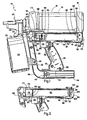
FIG. 1 is a side elevation of a combustion-powered fastener-driving tool with portions shown omitted for clarity and depicting a fuel cell in a first operational orientation; -
FIG. 2 is a fragmentary side elevation of the tool ofFIG. 1 shown with the fuel cell in a second operational orientation; -
FIG. 2A is a fragmentary plan view of the shelf mount in the assembled housing; -
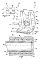
FIG. 3 is a perspective bottom view of a universal fuel cell door suitable for use in the present housing; and -
FIG. 4 is a vertical cross-section of a fuel line connector and associated components suitable for use in the present fuel cell chamber of the tool housing. - Referring now to
FIGs. 1 and 2 , a combustion-powered, fastener-driving tool suitable for incorporating the present handle housing is generally designated 10. While thetool 10 is depicted as being of the type described in the patents listed above, other types of fastener-driving tools are contemplated as having the potential of incorporation of the present handle housing. Thetool 10 includes amain housing 12, usually made of injection molded plastic. In thepresent tool 10, a variation of the housing construction is that a power source 14 (preferably a combustion-powered power source as is known in the art and shown hidden) is enclosed by apower source housing 16, and a separate handle housing generally designated 18 is joined to the power source housing and to thetool 10. - Other major components of the tool are the
nosepiece assembly 20, which contacts the workpiece and through which fasteners (not shown) are driven, and amagazine 22 providing a supply of fasteners and configured for feeding the fasteners to the nosepiece assembly. In the preferred embodiment, themagazine 22 is a coil-type, retaining a relatively large number of fasteners (at least 150) and the magazine advancement is powered by exhaust gases generated in the combustion process as described inU.S. Patent No. 5,558,264 . However, thepresent tool 10 is also contemplated as being used with straight, spring-advanced magazines having a reduced fastener capacity. Thecoil magazine 22 is configured for engagement with thenosepiece assembly 20 so that fasteners may be fed easily and with limited opportunity for becoming jammed in the delivery process. As such, aforward end 24 of themagazine 22 is slidingly engaged upon a receivingportion 26 thenosepiece assembly 20. - The
handle housing 18 is shown being secured along thepower source housing 16 from acombustion end 28 to anosepiece end 30 of the housing as well as thetool 10. As is well known in the art, thehandle housing 18 is provided in two halves joined along a vertical parting line and secured together with fasteners atseveral fastener points 32. Included on thehandle housing 18 is aprimary handle 34 configured for accommodating a primary hand used to control the operation of the tool. Theprimary handle 34 incorporates atrigger switch 36 configured for initiating combustion and other tool functions as is well known in the art. Afirst end 38 of theprimary handle 34, is closer to thepower source 14, and is joined to afuel cell chamber 40 which is directly connected to thetool 10 adjacent thepower source housing 16. Depending on the application, thehandle housing 18 may be directly fastened to thepower source housing 16, or may be fastened to thetool 10 to tightly engage the power source housing. To facilitate this engagement with thepower source housing 16, thefuel cell chamber 40 is preferably provided with conformingformations 42 which follow the outer contour of the power source housing at the point of contact. - A
second end 44 of theprimary handle 34 is connected to abattery housing 46 which is configured for retaining a battery as is known in the art. The battery is used to provide power to a control circuit which regulates many tool functions, including ignition, fan operation and fuel delivery. In thepreferred handle housing 18, asecondary handle 48 is connected at oneend 50 to thebattery housing 46 and at asecond end 52 to a support strut 54, the support strut being connected to ahousing 56 enclosing and defining thefuel cell chamber 40. Amagazine mounting point 58 is used to secure themagazine 22, which is also operationally engaged with thenosepiece assembly 20. - An important feature of the present
fuel cell chamber 40 is that it is dimensioned for operationally receiving afuel cell 60 in either one of a first orientation and a second orientation. Thefuel cell 60 has a generallycylindrical body 62 and has astem end 64 from which fuel is dispensed, as is known in the art, and abottom end 66 opposite the stem end. - A
shelf mount 68 is disposed in thefuel cell chamber 40 and is configured for engaging afuel injector 70 when thefuel cell 60 is in the first orientation (FIG. 1 ), and for supporting thebottom end 66 of the fuel cell when the fuel cell is in the second orientation (FIG. 2 ). Theshelf mount 68 is generally planar, joined atends 72 to main opposed front andrear walls chamber 40 and preferably also to aside wall 78. It is preferred that theshelf mount 68 is integrally formed with thefuel cell chamber 40, however, other fastening technologies are contemplated, including but not limited to chemical adhesives, ultrasonic bonding and the like. - A generally semi-circular or 'U'- shaped
recess 80 is defined by theshelf mount 68 and is configured for accommodating thefuel injector 70. As is known in the art, thefuel injector 70 is powered by the battery and controlled by the control circuit to dispense a measured amount of fuel for a single combustion cycle upon a closing of thetrigger switch 36. Thefuel injector 70 is in fluid communication with afuel line 82 which transports the fuel from the injector to a combustion chamber of thepower source 14, also known in the art. In that thefuel injector 70 has a generallycylindrical body 84, theshelf mount 68 is dimensioned to receive the body, so that when mating halves of thehandle housing 18 are joined, thefuel injector 70 is securely held in place (best seen inFIG. 2A ). - In another embodiment the
fuel injector 70 is held in place in thefuel cell chamber 40 by a pair of spaced, radially projectingannular ribs 86 which straddle theshelf mount 68. Corresponding halves of thehandle housing 18 join to substantially surround the injector 70 (FIG. 2A ). Theshelf mount 68 defines afuel injector chamber 88 between the mount and alower wall 90 of thefuel cell chamber 40. - Referring now to
FIGs. 1 and4 , a majority of thefuel injector body 84 is located within thefuel injector chamber 88. To facilitate connection of thefuel line 82 to thefuel injector 70, a push-onconnector 92 is provided. It has been found that conventional fittings for such fuel lines which include threaded connections and 90° elbows have a tendency to restrict or reduce fuel flow. To address these concerns, theconnector 92 is configured to allow a push-on attachment of an end 94 of thefuel line 82 to the connector, so that the line is sealingly connected to thefuel injector 70. Anexterior surface 96 of theconnector 92 is provided with a plurality of radially projecting spacedannular ribs 98 for secure and sealing engagement in anaperture 100 of an electronic fuel injector (EFI) valve of thefuel injector 70 which is part of the fuel passageway of the injector. - A
first end 102 of theconnector 92 is configured to slidingly yet sealingly receive thefuel line 82. Asecond end 104 of theconnector 92 has asmaller aperture 105 than thefirst end 102, and is dimensioned to correspond to an inner diameter of thefuel line 82. Preferably, theaperture 105 is no smaller than the inner fuel line diameter. Thus, thesecond end 104 acts as a stop preventing further axial insertion of thefuel line 82 into theinjector 70, while also facilitating fuel flow by not obstructing the fuel passageway. By using theconnector 92, thefuel line 82 is securely and sealingly held in place with a reduced number of components. Anidentical connector 92 is employed at an opposite end of thefuel line 82 where it is inserted into the cylinder head (not shown). - Referring now to
FIG. 2 , a feature of thepresent handle housing 18 is that, in an alternative to the arrangement depicted inFIG. 1 , thefuel cell 60 can be inserted into thechamber 40 so that thebottom end 66 rests upon, and is supported by theshelf mount 68. This orientation of thefuel cell 60 is employed when, instead of anelectronic fuel injector 70, thetool 10 is provided with amechanical fuel dispenser 106. Such adispenser 106 dispenses a measured quantity of fuel as thenosepiece assembly 20 is actuated, and/or thetrigger switch 36 is closed. Asuitable dispenser 106 is disclosed in commonly-assignedU.S. Patent No. 6,302,297 . - With the
fuel cell 60 oriented as depicted inFIG. 2 , the fuel is dispensed near thecombustion end 28 of thetool 10 and close to the combustion chamber (not shown). Thus, the fuel is dispensed in an opposite direction than when theinjector 70 is provided as discussed in relation toFIG. 1 . Theshelf mount 68 is disposed relative to thefuel cell chamber 40 so that when the fuel cellbottom end 66 is resting upon the shelf mount, thedispenser 106 is in operational relationship to a fuel passage in fluid communication with the combustion chamber. - Referring now to
FIGs. 1 and4 , access to thefuel cell chamber 40 is controlled by afuel cell door 110, which is pivotably engageable on thehandle housing 18 for selectively opening the fuel cell chamber. Thedoor 110 is shaped like an inverted 'L' when viewed from the side, and includes a body made up of afirst leg 112 and asecond leg 114 joined along a common edge to form the 'L' shape, which is preferably integrally formed as through injection molding or similar techniques. Laterally outwardly projectinglugs 116 on thefirst leg 112 are pivotably engageable innoncircular apertures 118 on the handle housing (FIG. 2 ). The noncircular configuration of theapertures 118 provides for a sliding/pivoting action which allows thedoor 110 to totally clear thechamber 40 for easy insertion and retraction of thefuel cell 60. In the preferred embodiment, thelugs 116 are joined tocam formations 120 which guide and support thefuel cell 60. - A main function of the
second leg 114 is closing off thefuel cell chamber 40 and preventing the entry of dirt and debris. Also on thesecond leg 114 of thedoor 110 are found separate formations for engaging the fuel cell in each of the first and second orientations depicted respectively inFIGs. 1 and 2 . More specifically, these formations include a generally centrally locatedboss 122 for engaging thebottom end 66 of thefuel cell 60 in the first orientation where theinjector 70 is employed, and a pair of spacedrails 124 for engaging themechanical fuel dispenser 106. It is preferred that theboss 122 be removable from theleg 114 and have a generally cylindrical shape, with anouter wall 126 defining aninterior chamber 128 in which a recessedfloor 130 is provided. Since theboss 122 is removable from the door, thefloor 130 is preferably provided with an attachment bore 131 configured for receiving a threaded fastener (not shown) for securing the boss to theleg 114. - The
rails 124 project perpendicularly from thesecond leg 114 as does theboss 122, but the rails extend longitudinally generally parallel to the second leg. Preferably, therails 124 extend approximately the full length of thesecond leg 114, however other lengths are contemplated depending on the application. As such, therails 124 each define aplanar slide track 125 which slides relative to thefuel dispenser 106 as thedoor 110 is closed. The preferablysolid rail walls 124 are also helpful in guiding thedispenser 106 in position and supporting it during operation. In the configuration ofFIG. 2 wherefuel cell 60 is oriented so that thedispenser 106 is employed, it will be understood that theboss 122 is removed from thedoor 110 prior to assembly. - In keeping with the design objective of providing a
handle housing 18 configured to accommodate a tool configuration wherein fuel is provided either by electronic fuel injection or mechanical fuel dispensing, when thefuel cell 60 is in the position for mechanical fuel delivery (FIG. 2 ), a fuel elbow fitting 140 provides fluid communication between themechanical fuel dispenser 106 and thecylinder head 138. Accordingly, thehandle housing 18, and specifically thefuel cell chamber 40 defines anelbow pocket 142 for accommodating thefuel fitting 140. Theelbow pocket 142 is basically an opening in thefront wall 74 large enough to accommodate thefuel elbow fitting 140. When thetool 10 is configured so that thefuel injector 70 is employed and thefuel cell 60 is oriented as inFIG. 1 , it will be seen that thefuel elbow pocket 142 will not be used, since fuel is transported to the combustion chamber using thefuel line 82. - Thus, the
present handle housing 18 features thefuel cell chamber 40 which is dimensioned for operationally accommodating thefuel cell 60 in either of two operational orientations. Regardless of whether thetool 10 is configured for use of theelectronic fuel injector 70 or themechanical fuel dispenser 106, thesame housing 18 is employable. Theshelf mount 68 is particularly useful in retaining the fuel injector when thefuel cell 60 is in a first operational orientation, and alternatively for providing a support base for the fuel cell when in a second operational orientation. In addition, the universalfuel cell door 110 is provided which is suitable for either tool orientation. As such, the manufacturer need not create special tooling and/or inventory of components for each type of tool configuration. - While particular embodiments of the present fuel cell compartment for a combustion-powered tool have been described herein, it will be appreciated by those skilled in the art that changes and modifications may be made thereto without departing from the invention in its broader aspects and as set forth in the following clai ms.
Claims (3)
- A universal fuel door (110) for use in a combustion-powered tool (10) having a power source (14) and a housing (12) defining a fuel cell chamber (40) with an open end for receiving a fuel cell (60), said door comprising:a door body configured for pivotably engaging the open end of the fuel cell;at least one first formation (122) for engaging the fuel cell upon insertion into the fuel cell chamber in a first orientation; andat least one second formation (124) for engaging the fuel cell upon insertion into the fuel cell chamber in a second orientation,characterised in that said formations include a removable central boss (122) for engaging the fuel cell in the first orientation, and a pair of spaced rails (124) for engaging the fuel cell in the second orientation.
- The fuel door (110) of claim 1, wherein said rails (124) are generally parallel to each other and said boss (122) is located between said rails.
- The fuel door (110) of claim 1, wherein said rails (124) define a track for sliding engagement of a fuel dispenser (106).
Applications Claiming Priority (3)
| Application Number | Priority Date | Filing Date | Title |
|---|---|---|---|
| US60630904P | 2004-09-01 | 2004-09-01 | |
| US10/959,845 US7546938B2 (en) | 2004-09-01 | 2004-10-06 | Fuel cell compartment for combustion-powered tool |
| PCT/IB2005/052811 WO2006025010A2 (en) | 2004-09-01 | 2005-08-26 | Fuel cell compartment for combustion-powered tool |
Publications (2)
| Publication Number | Publication Date |
|---|---|
| EP1784285A2 EP1784285A2 (en) | 2007-05-16 |
| EP1784285B1 true EP1784285B1 (en) | 2009-10-07 |
Family
ID=35709353
Family Applications (1)
| Application Number | Title | Priority Date | Filing Date |
|---|---|---|---|
| EP05781448A Expired - Fee Related EP1784285B1 (en) | 2004-09-01 | 2005-08-26 | Fuel cell compartment for combustion-powered tool |
Country Status (11)
| Country | Link |
|---|---|
| US (1) | US7546938B2 (en) |
| EP (1) | EP1784285B1 (en) |
| JP (1) | JP2008511457A (en) |
| KR (1) | KR20070045302A (en) |
| AU (1) | AU2005278793B2 (en) |
| BR (1) | BRPI0513554A (en) |
| CA (1) | CA2589593C (en) |
| DE (1) | DE602005017051D1 (en) |
| MX (1) | MX2007002404A (en) |
| NZ (1) | NZ553458A (en) |
| WO (1) | WO2006025010A2 (en) |
Families Citing this family (11)
| Publication number | Priority date | Publication date | Assignee | Title |
|---|---|---|---|---|
| AU2008201129B2 (en) * | 2007-04-04 | 2011-01-27 | Hilti Ag | Combustion-operated setting tool |
| DE102008004949A1 (en) * | 2008-01-18 | 2009-07-23 | Sabik Informationssysteme Gmbh | Fuel cell system with a stack and method for changing the stack |
| ITMI20080171U1 (en) * | 2008-05-21 | 2009-11-22 | Atlas Copco Blm Srl | ELECTRONIC DYNAMOMETRIC KEY WITH REMOVABLE BATTERY AND SYSTEM WITH SUCH KEY |
| US9802303B2 (en) | 2010-04-13 | 2017-10-31 | Illinois Tool Works Inc. | Interface for fuel delivery system for combustion fastener driver |
| US8302831B2 (en) * | 2010-04-13 | 2012-11-06 | Illinois Tool Works Inc. | Flanged fuel cell and locating structure for combustion tool |
| US8939339B2 (en) | 2010-04-13 | 2015-01-27 | Illinois Tool Works Inc. | Interface for fuel delivery system for combustion nailer |
| US8440362B2 (en) | 2010-09-24 | 2013-05-14 | Bloom Energy Corporation | Fuel cell mechanical components |
| JP5652262B2 (en) * | 2011-03-02 | 2015-01-14 | マックス株式会社 | Gas fired driving tool |
| CN103975055B (en) * | 2011-10-10 | 2016-05-04 | 德国达斯其普信息与程序技术有限公司 | Comprise the biotechnology device of bioreactor, for the effluent air temp control device of bioreactor and for the treatment of the method for the discharge air-flow of biotechnology device |
| US9755263B2 (en) | 2013-03-15 | 2017-09-05 | Bloom Energy Corporation | Fuel cell mechanical components |
| US10651496B2 (en) | 2015-03-06 | 2020-05-12 | Bloom Energy Corporation | Modular pad for a fuel cell system |
Family Cites Families (10)
| Publication number | Priority date | Publication date | Assignee | Title |
|---|---|---|---|---|
| US4403722A (en) * | 1981-01-22 | 1983-09-13 | Signode Corporation | Combustion gas powered fastener driving tool |
| US5263439A (en) * | 1992-11-13 | 1993-11-23 | Illinois Tool Works Inc. | Fuel system for combustion-powered, fastener-driving tool |
| US5558264A (en) * | 1995-02-13 | 1996-09-24 | Illinois Tool Works Inc. | Combustion-powered, fastener-driving tool with gas-actuated, fastener-feeding mechanism |
| US5680980A (en) * | 1995-11-27 | 1997-10-28 | Illinois Tool Works Inc. | Fuel injection system for combustion-powered tool |
| FR2774934B1 (en) * | 1998-02-13 | 2000-03-31 | Spit Soc Prospect Inv Techn | COMPRESSED GAS FIXING APPARATUS |
| US6302297B1 (en) * | 2000-09-06 | 2001-10-16 | Illinois Tool Works Inc. | External metering valve for a fuel cell |
| US20030034377A1 (en) | 2001-08-16 | 2003-02-20 | Porth Chris H. | Combustion tool with coil magazine |
| US6786378B2 (en) * | 2002-01-09 | 2004-09-07 | Illinois Tool Works Inc. | Fastener tool having auxiliary fuel cell metering valve stem seal adaptor |
| US6722549B2 (en) * | 2002-05-08 | 2004-04-20 | Yury Shkolnikov | Arm member for fastener driving tool |
| DE10222338A1 (en) * | 2002-05-21 | 2003-12-04 | Hilti Ag | Combustion-powered setting tool |
-
2004
- 2004-10-06 US US10/959,845 patent/US7546938B2/en not_active Expired - Fee Related
-
2005
- 2005-08-26 EP EP05781448A patent/EP1784285B1/en not_active Expired - Fee Related
- 2005-08-26 CA CA2589593A patent/CA2589593C/en not_active Expired - Fee Related
- 2005-08-26 JP JP2007529110A patent/JP2008511457A/en not_active Ceased
- 2005-08-26 MX MX2007002404A patent/MX2007002404A/en active IP Right Grant
- 2005-08-26 DE DE602005017051T patent/DE602005017051D1/en active Active
- 2005-08-26 KR KR1020077004786A patent/KR20070045302A/en not_active Application Discontinuation
- 2005-08-26 NZ NZ553458A patent/NZ553458A/en unknown
- 2005-08-26 BR BRPI0513554-0A patent/BRPI0513554A/en not_active IP Right Cessation
- 2005-08-26 AU AU2005278793A patent/AU2005278793B2/en active Active
- 2005-08-26 WO PCT/IB2005/052811 patent/WO2006025010A2/en active Application Filing
Also Published As
| Publication number | Publication date |
|---|---|
| US20060042571A1 (en) | 2006-03-02 |
| US7546938B2 (en) | 2009-06-16 |
| KR20070045302A (en) | 2007-05-02 |
| MX2007002404A (en) | 2007-08-24 |
| WO2006025010A2 (en) | 2006-03-09 |
| AU2005278793A1 (en) | 2006-03-09 |
| CA2589593C (en) | 2010-11-09 |
| CA2589593A1 (en) | 2006-03-09 |
| AU2005278793B2 (en) | 2009-03-19 |
| NZ553458A (en) | 2010-09-30 |
| WO2006025010A3 (en) | 2006-08-10 |
| EP1784285A2 (en) | 2007-05-16 |
| JP2008511457A (en) | 2008-04-17 |
| DE602005017051D1 (en) | 2009-11-19 |
| BRPI0513554A (en) | 2008-05-06 |
Similar Documents
| Publication | Publication Date | Title |
|---|---|---|
| EP1784285B1 (en) | Fuel cell compartment for combustion-powered tool | |
| EP1791680B1 (en) | Gas driven actuation feed tube for combustion powered fastener-driving tool | |
| US8302831B2 (en) | Flanged fuel cell and locating structure for combustion tool | |
| AU2008276314B2 (en) | Actuator pin guide for a fastener driving tool | |
| EP2766150B1 (en) | Interface for fuel delivery system for combustion nailer | |
| US20080223898A1 (en) | Nose assembly for a fastener driving tool | |
| US20220355457A1 (en) | Fastener driving tool | |
| WO2011028721A1 (en) | Fuel cell actuation mechanism for combustion-powered tool | |
| CN100571994C (en) | The fuel cell compartment of combustion-powered tool |
Legal Events
| Date | Code | Title | Description |
|---|---|---|---|
| PUAI | Public reference made under article 153(3) epc to a published international application that has entered the european phase |
Free format text: ORIGINAL CODE: 0009012 |
|
| 17P | Request for examination filed |
Effective date: 20070322 |
|
| AK | Designated contracting states |
Kind code of ref document: A2 Designated state(s): DE FR GB |
|
| DAX | Request for extension of the european patent (deleted) | ||
| RBV | Designated contracting states (corrected) |
Designated state(s): DE FR GB |
|
| 17Q | First examination report despatched |
Effective date: 20080213 |
|
| GRAP | Despatch of communication of intention to grant a patent |
Free format text: ORIGINAL CODE: EPIDOSNIGR1 |
|
| GRAS | Grant fee paid |
Free format text: ORIGINAL CODE: EPIDOSNIGR3 |
|
| GRAA | (expected) grant |
Free format text: ORIGINAL CODE: 0009210 |
|
| AK | Designated contracting states |
Kind code of ref document: B1 Designated state(s): DE FR GB |
|
| REG | Reference to a national code |
Ref country code: GB Ref legal event code: FG4D |
|
| REF | Corresponds to: |
Ref document number: 602005017051 Country of ref document: DE Date of ref document: 20091119 Kind code of ref document: P |
|
| PLBE | No opposition filed within time limit |
Free format text: ORIGINAL CODE: 0009261 |
|
| STAA | Information on the status of an ep patent application or granted ep patent |
Free format text: STATUS: NO OPPOSITION FILED WITHIN TIME LIMIT |
|
| 26N | No opposition filed |
Effective date: 20100708 |
|
| PGFP | Annual fee paid to national office [announced via postgrant information from national office to epo] |
Ref country code: DE Payment date: 20130828 Year of fee payment: 9 |
|
| PGFP | Annual fee paid to national office [announced via postgrant information from national office to epo] |
Ref country code: FR Payment date: 20130819 Year of fee payment: 9 Ref country code: GB Payment date: 20130827 Year of fee payment: 9 |
|
| REG | Reference to a national code |
Ref country code: DE Ref legal event code: R119 Ref document number: 602005017051 Country of ref document: DE |
|
| GBPC | Gb: european patent ceased through non-payment of renewal fee |
Effective date: 20140826 |
|
| REG | Reference to a national code |
Ref country code: DE Ref legal event code: R119 Ref document number: 602005017051 Country of ref document: DE Effective date: 20150303 |
|
| REG | Reference to a national code |
Ref country code: FR Ref legal event code: ST Effective date: 20150430 |
|
| PG25 | Lapsed in a contracting state [announced via postgrant information from national office to epo] |
Ref country code: GB Free format text: LAPSE BECAUSE OF NON-PAYMENT OF DUE FEES Effective date: 20140826 Ref country code: DE Free format text: LAPSE BECAUSE OF NON-PAYMENT OF DUE FEES Effective date: 20150303 |
|
| PG25 | Lapsed in a contracting state [announced via postgrant information from national office to epo] |
Ref country code: FR Free format text: LAPSE BECAUSE OF NON-PAYMENT OF DUE FEES Effective date: 20140901 |