EP1327501A2 - Fastener tool having auxiliary fuel cell metering valve stem seal adaptor - Google Patents
Fastener tool having auxiliary fuel cell metering valve stem seal adaptor Download PDFInfo
- Publication number
- EP1327501A2 EP1327501A2 EP03290040A EP03290040A EP1327501A2 EP 1327501 A2 EP1327501 A2 EP 1327501A2 EP 03290040 A EP03290040 A EP 03290040A EP 03290040 A EP03290040 A EP 03290040A EP 1327501 A2 EP1327501 A2 EP 1327501A2
- Authority
- EP
- European Patent Office
- Prior art keywords
- tool
- metering valve
- stem
- valve stem
- combustion chamber
- Prior art date
- Legal status (The legal status is an assumption and is not a legal conclusion. Google has not performed a legal analysis and makes no representation as to the accuracy of the status listed.)
- Granted
Links
Images



Classifications
-
- B—PERFORMING OPERATIONS; TRANSPORTING
- B25—HAND TOOLS; PORTABLE POWER-DRIVEN TOOLS; MANIPULATORS
- B25C—HAND-HELD NAILING OR STAPLING TOOLS; MANUALLY OPERATED PORTABLE STAPLING TOOLS
- B25C1/00—Hand-held nailing tools; Nail feeding devices
- B25C1/04—Hand-held nailing tools; Nail feeding devices operated by fluid pressure, e.g. by air pressure
-
- B—PERFORMING OPERATIONS; TRANSPORTING
- B25—HAND TOOLS; PORTABLE POWER-DRIVEN TOOLS; MANIPULATORS
- B25C—HAND-HELD NAILING OR STAPLING TOOLS; MANUALLY OPERATED PORTABLE STAPLING TOOLS
- B25C1/00—Hand-held nailing tools; Nail feeding devices
- B25C1/08—Hand-held nailing tools; Nail feeding devices operated by combustion pressure
Definitions
- the present invention relates generally to fastener-driving tools, and more particularly to a new and improved seal adaptor which is structured so as to effectively interface between the outwardly projecting valve stem of a metering valve operatively associated with a fuel cell power supply for the fastener-driving tool, and a tool stem of the fastener-driving tool whereby secure sealed conditions are always maintained between the metering valve stem and the tool stem regardless of the disposition or orientation of the fuel cell with respect to the tool during the normal operative cyclical firing of the fastener-driving tool.
- Fuel cells are conventionally used as a power supply or a source of power for fastener-driving tools. Examples of fuel cells, and fastener-driving tools utilizing the same, are disclosed within United States Patents 5,115,944, 4,522,162, 4,483,474, 4,483,473 and 4,403,722.
- a typical fuel-cell powered fastener-driving tool is partially disclosed and is generally indicated by the reference character 10.
- the tool 10 comprises a combustion chamber 12 within which an air-fuel mixture distribution fan 14 is disposed, and a fuel charge conduit 16 is defined within the head 18 of a cylinder block 19.
- the fuel cell is disclosed at 20 and is provided with a dispensing valve unit 22.
- Dispensing valve unit 22 has, in turn, a metering valve unit 24 operatively connected thereto wherein the latter is adapted to discharge, dispense, or inject a predetermined amount or dosage of fuel from the fuel cell 20 into the tool combustion chamber 12 each time a fastener-driving and firing operational cycle is indicated.
- the metering valve unit 24 comprises a valve stem 26, and the tool 10 further comprises a tool stem 28 which is fluidically connected at one end thereof to the fuel charge conduit 16, and is operatively engaged at its opposite end to the metering valve stem 26 so as to provide a fluidic flow path from the fuel cell 20, the dispensing valve unit 22, and the metering valve unit 24 into the tool combustion chamber 12.
- the tool stem 28 comprises a axial stem portion 30 which is provided with an axial bore 32 defining a fluid passageway for the fuel to be dispensed into the tool combustion chamber 12, and a head end portion 34 which is adapted to be engaged with the free end portion of the metering valve stem 26. More particularly, the head end portion 34 of the tool stem 28 is provided with a counterbored region 36 within which the free end portion of the metering valve stem 26 is adapted to be received or seated.
- both the valve stem 26 and the tool stem 28 are fabricated either from, for example, a suitable plastic material or from a suitable metal material, the two components are operatively engaged with each other so as to effectively establish either a plastic-to-plastic contact or engagement interface or a metal-to-metal contact or engagement interface. Accordingly, a fluidically sealed interface between the valve stem 26 and tool stem 28 components is not in fact capable of being established.
- valve stem 26 and tool stem 28 elements cooperate together so as to effectively form or establish the necessary fuel conduit interface, as well as the necessary fluidic sealing of such conduit interface as determined by means of the interengagement of such stem elements 26,28, high manufacturing tolerances are required in connection with the fabrication of such stem elements 26,28 in order to achieve, as best as possible, the aforenoted sealing function between the stem elements 26,28. Still further, the interengagement of the valve stem 26 and tool stem 28 components limits the necessary movements of the fuel cell 20 and the metering valve 24 components within the tool 10.
- valve stem 26 causes the valve stem 26, as well as the tool stem 28, to undergo bending stresses or strains which can lead to structural fatigue, cracking, breakage, failure, and additional fuel leakage within the tool 10.
- auxiliary fuel cell metering valve stem seal adaptor for use in conjunction with the fuel cell metering valve stem and the tool valve stem of a fuel cell powered fastener-driving tool.
- Another object of the present invention is to provide a new and improved auxiliary fuel cell metering valve stem seal adaptor for use in conjunction with the fuel cell metering valve stem and the tool valve stem of a fuel cell powered fastener-driving tool wherein the operational drawbacks and deficiencies of conventional operative engagement structure defined between the metering valve stem and the tool stem of PRIOR ART fuel cell powered fastener-driving tools can effectively be overcome.
- An additional object of the present invention is to provide a new and improved auxiliary fuel cell metering valve stem seal adaptor for use in conjunction with the fuel cell metering valve stem and the tool valve stem of a fuel cell powered fastener-driving tool wherein enhanced sealing characteristics or properties are able to be achieved between the metering valve stem and the tool valve stem.
- a further object of the present invention is to provide a new and improved auxiliary fuel cell metering valve stem seal adaptor for use in conjunction with the fuel cell metering valve stem and the tool valve stem of a fuel cell powered fastener-driving tool wherein enhanced sealing characteristics or properties are able to be achieved between the metering valve stem and the tool valve stem such that fuel leakage internally within the fastener-driving tool is effectively prevented.
- a last object of the present invention is to provide a new and improved auxiliary fuel cell metering valve stem seal adaptor for use in conjunction with the fuel cell metering valve stem and the tool valve stem of a fuel cell powered fastener-driving tool wherein enhanced sealing characteristics or properties are able to be achieved between the metering valve stem and the tool valve stem such that bending stresses, strain, and fatigue are no longer impressed upon the metering valve stem and the tool stem components so as to respectively enhance the service lives thereof.
- the invention relates to a metering valve assembly according to claim 1, a metering valve-tool stem assembly according to claim 4 and to a combustion-powered fastener-driving tool according to claim 10.
- FIGURE 4 a fuel cell-powered fastener-driving tool, within which the new and improved auxiliary fuel cell metering valve stem seal adaptor, constructed in accordance with the principles and teachings of the present invention can be utilized, is disclosed and is generally indicated by the reference character 110.
- the tool 110 illustrated within FIGURE 4 is similar to the tool 10 illustrated within FIGURE 1 and therefore component parts of the tool 110 which correspond to those component parts of the tool 10 will be designated by corresponding reference characters except that the reference characters for the component parts of the tool 110 will be within the 100 series.
- the fastener-driving tool 110 is seen to comprise a body portion 101 having a combustion chamber 112 defined therein within which an air-fuel mixture distribution fan 114 is located.
- a piston 102 is vertically movable within a piston chamber 103 and a bumper member 104 is located within the bottom end portion of the piston chamber 103 to serve as a shock-absorber for the piston 102 at the end of its downward movement or stroke.
- the piston 102 has a driver blade 105 operatively connected thereto for driving and discharging nail fasteners out of the tool 110 and into a workpiece or substrate, and the nail fasteners are housed in a collated manner within a tool magazine 106 which is integrally connected to a tool handle portion 107 of the tool 110 within which a tool-firing trigger mechanism 108 is mounted.
- a fuel cell chamber 109 is defined between the handle portion 107 of the tool 110 and the combustion chamber 112 so as to house a fuel cell, not shown in FIGURE 4, which is similar to the fuel cell 20 disclosed within the conventional PRIOR ART tool 10 shown in FIGURE 1.
- the fuel cell will also have a metering valve assembly 124, also not shown in FIGURE 4 but shown in FIGURE 5, operatively connected thereto, and the metering valve assembly 124 has a valve stem 126 which is adapted to be operatively mated with a tool stem 128 which is disclosed in detail in FIGURE 6.
- the valve stem 126 is in turn fluidically connected to a fuel charge conduit 116 defined within the head 118 of a cylinder block 119.
- the fuel cell chamber 109 is provided with a pivotal cover member 111, and it is seen that the fuel cell chamber cover member 111 comprises a mounting bracket portion 113 which has a lower end section 115 pivotally mounted upon a first trunnion 117.
- the first trunnion 117 is also vertically slidable within a slot 121 formed within the fuel cell chamber housing 123, and the cover member 111 also includes a dependent leg portion 125 which is connected, but separately and independently movable with respect, to the mounting bracket portion 113.
- the fastener-driving tool 110 is further provided with a workpiece contacting element 127 which is movably mounted upon a nosepiece portion 129 of the tool 110 as is well-known in the art, and the workpiece contacting element 127 is operatively connected to the fuel cell cover member 111, by means not shown, such that when the fuel cell cover member 111 is disposed in its closed position and the workpiece contacting element 127 is moved relatively upwardly as a result of the tool 110 being moved relatively downwardly into engagement with a workpiece or substrate into which the nail fasteners are to be driven, the fuel cell cover member 111 will be pivotally moved around a second trunnion 131 such that the dependent leg portion 125 of the fuel cell cover member 111 will cause movement of the metering valve 124 relative to the metering valve stem 126 so as to inject a predetermined dosage of fuel from the fuel cell into the combustion chamber 112.
- the fastener-driving tool 110 is fired, as a result of the air-fuel mixture within the combustion chamber 112 being ignited, thereby driving a fastener into the workpiece or substrate.
- the metering valve assembly 124 is seen to comprise a main housing 133 upon which a female connector portion 135 is integrally provided for fluidic connection to a dispensing valve similar to the dispensing valve 22 of the fuel cell 20 as shown in FIGURE 1.
- the metering valve stem is disclosed at 126 and it is seen that and internally disposed end of the metering valve stem 126 is disposed within a chamber 138.
- a coil spring 140 is disposed within the chamber 138 such that one end of the coil spring 140 is fixedly engaged with an internal surface portion of an end wall 142 of the housing 133, while the other end of the coil spring 140 is engaged with a shoulder portion 144 of the metering valve stem 126.
- a plug 146 is fixedly mounted within the open end of the metering valve housing 133 so as to secure a gasket member 148 within the housing 133.
- the metering valve stem 126 further comprises an annular flanged portion 150, and as a result of the biasing force of the spring 140, the flanged portion 150 of the metering valve stem 126 is normally seated upon the gasket member 148 so as to normally prevent fuel flow through the metering valve stem 126.
- the metering valve stem 126 further comprises an axially extending fluid bore 152, and a transverse through-bore 154.
- the upstream shank portion of the metering valve stem 126 is tapered as at 156, and an annular seal member 158, having an annular sealing rib 160, is disposed within a fuel metering chamber 162 wherein the annular sealing rib 160 is normally loosely disposed in contact with the outer peripheral surface portion of the tapered metering valve stem shank portion 156. Consequently, when the fastener-driving tool 110 has not as yet been activated, fuel from a fuel cell such as that disclosed at 20 in FIGURE 1 is dispensed through its dispensing valve 22, into spring chamber 138, and into fuel metering chamber 162.
- Flanged portion 150 is also unseated from gasket member 148, and transverse bore 154 is moved beyond the vertical plane of gasket member 148 so as to receive the fuel from chamber 162 and thereby permit the fuel to be conducted toward the tool stem 128 by means of axial bore 152.
- the interface defined between such stem components simply comprises a plastic-to-plastic or metal-to-metal interface whereby fuel leakage can occur. This is an undesirable operative situation, and it is therefore desired to prevent such fuel leakage at the operative interface defined between the metering valve stem 126 and the tool stem 128.
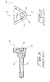
- an auxiliary elastomeric sealing adaptor has been developed so as to be fixedly mounted upon the free distal end portion of the metering valve stem 126 and to be accommodated within the upstream head portion of the tool stem 128 so as to provide a fluidic seal between the metering valve stem 126 and the tool stem 128. More particularly, as can be appreciated from FIGURES 6-8, the auxiliary elastomeric sealing adaptor is disclosed at 164.
- the elastomeric adaptor 164 comprises a substantially hollow or tubular body portion 166 having a substantially cylindrical cross-sectional configuration, while the forward or downstream end portion 168 of the adaptor 164 is chamfered so as to have a substantially annular frusto-conical configuration.
- the front end wall 170 of the adaptor 164 is provided with a through-bore 172, and the body portion 166 is counterbored as at 174 so as to permit the elastomeric adaptor 164 to be mounted upon the free or distal end portion of the metering valve stem 126 as can be best appreciated from FIGURE 8.
- the entrance to the counterbored portion 174 of the adaptor 164 is chamfered as at 176 so as to facilitate the mounting of the adaptor upon the metering valve stem 126.
- the structure of the tool stem 128 has been somewhat modified when compared to the structure of the conventional PRIOR ART tool stem 28 in that the upstream head portion 134 of the tool stem 128 has an enlarged counterbored section 178 defined therein so as to be capable of effectively accommodating the elastomeric adaptor 164.
- the configuration of the counterbored section 178 is such as to effectively match the cylindrical and frusto-conical portions 166,168 of the adaptor 164 so as to facilitate the fluidic sealing engagement between the elastomeric adaptor 164 and the tool stem 128.
- counterbored section 178 of tool stem head section 134 is seen to comprise a substantially cylindrical portion 180 and a frusto-conical portion 182, and the mated engagement or mounted position of the adaptor 164 within the tool stem 128 is best appreciated from FIGURE 8.
- auxiliary elastomeric sealing adaptor which effectively provides a high degree of sealing, and prevents fuel leakage, between the metering valve stem and the tool stem components of a fuel-cell powered fastener-driving tool despite bending, tilting, or pivotal movements of the metering valve stem attendant a fastener-firing operation.
- the incorporation of the elastomeric adaptor between the stem components reduces the need for high tolerance manufacturing techniques and also enhances the service lives of the stem components.
Landscapes
- Engineering & Computer Science (AREA)
- Mechanical Engineering (AREA)
- Chemical & Material Sciences (AREA)
- Combustion & Propulsion (AREA)
- Physics & Mathematics (AREA)
- Fluid Mechanics (AREA)
- Portable Nailing Machines And Staplers (AREA)
- Feeding And Controlling Fuel (AREA)
- Lift Valve (AREA)
- Check Valves (AREA)
Abstract
Description
Claims (10)
- A metering valve assembly (124) for use in connection with a tool stem (128) of a fastener-driving tool (110) for dispensing a predetermined metered amount of fuel to be injected into the tool combustion chamber (112), comprising:a metering valve (124) for dispensing a predetermined metered amount of fuel to be injected into a combustion chamber (112) of a tool (110);a metering valve stem (126) fixedly mounted upon said metering valve for cooperating with a tool stem (128) in order to define a fluid flow path from said metering valve toward the combustion chamber of the tool; characterized in that it further comprisesan elastomeric adaptor (164) mounted upon said metering valve stem (126) so as to be disposed in sealed engagement with the tool stem (128) of the tool and thereby define a sealed fluid flow path leading from said metering valve (124) toward the combustion chamber (112) of the tool.
- The metering valve assembly as set forth in Claim 1, wherein:said elastomeric adaptor (164) has a substantially cylindrical body section (166) and a frusto-conical leading end section for mating with the tool stem (128) of the tool in a sealed manner.
- The metering valve assembly as set forth in Claim 2, wherein:said elastomeric adaptor (164) comprises a hollow cap member (166) adapted to be seated upon a free distal end portion of said metering valve stem (126) and having an axially extending fluidic bore (172) defined therethrough for fluidically connecting said metering valve stem (126) to the tool stem (128) of the tool.
- A metering valve-tool stem assembly for use in connection with a fastener-driving tool for dispensing a predetermined metered amount of fuel to be injected into the tool combustion chamber (112), comprising:a tool stem (128) fixedly mounted upon a tool (110) and a metering valve (124) for dispensing a predetermined metered amount of fuel to be injected into the combustion chamber (112) of the tool;a metering valve stem (126) fixedly mounted upon said metering valve (124) for cooperating with said tool stem (128) in order to define a fluid flow path from said metering valve (124) toward the combustion chamber (112) of the tool, characterized in that the tool stem (128) has a recess portion (178) defined therein ;the metering valve is a valve according to one of claims 1 to 3 ; andthe adaptor (164) is disposed within said recess portion (178) of said tool stem (128).
- The metering valve-tool stem assembly as set forth in Claim 4, wherein:said tool stem (128) comprises an axially extending stem portion (130) having a first distal end (130) adapted to be fluidically connected to the combustion chamber (112) of the fastener-driving tool, and a head member (134) integrally formed upon a second, opposite proximal end adapted to be fluidically sealed with said elastomeric adaptor (164) mounted upon said metering valve stem (128).
- The metering valve-tool stem assembly as set forth in Claim 5, wherein:said axially extending stem portion (130) has an axially extending fluid passageway (132) defined therein; andsaid head member (134) of said tool stem (128) has a counterbored recessed portion (178) defined therein, fluidically connected to said axially extending fluid passageway defined within said axially extending stem portion, for accommodating said elastomeric adaptor (164) in a fluidically sealed manner.
- The metering valve-tool stem assembly as set forth in Claim 6, wherein:said counterbored recessed portion (178) defined within said head member (134) of said tool stem (128) has a substantially cylindrical configuration within the vicinity of the entrance region to said counterbored recessed portion (178), and an internal frusto-conical configuration (182).
- The metering valve-tool stem assembly as set forth in Claim 7, wherein:said elastomeric adaptor (164) has a substantially cylindrical body section and a frusto-conical leading end section (168) for respectively mating with said substantially cylindrical entrance portion (178) and said internal frusto-conical portion (182) of said tool stem (128) in a fluidically sealed manner.
- The metering valve-tool stem assembly as set forth in Claim 6, wherein:said elastomeric adaptor (164) comprises a hollow cap member adapted to be seated upon a free distal end portion of said metering valve stem (126) and having an axially extending fluidic bore (174) defined therethrough for fluidically connecting said metering valve stem (126) to said axially extending fluid passageway (132) defined within said axially extending stem portion (130) of said tool stem (128).
- A combustion-powered fastener-driving tool (110), comprising:a combustion chamber (112);a fuel cell containing fuel to be injected into said combustion chamber;a metering valve-tool stem assembly for dispensing a predetermined metered amount of fuel to be injected into the tool combustion chamber (112), comprising:a tool stem (128) fixedly mounted upon said fastener-driving tool for partially defining a fuel fluid flow path toward said combustion chamber (112);a metering valve operatively mounted upon said fuel cell, characterized in thatsaid metering valve-tool stem assembly is an assembly according to one of claims 4 to 9.
Applications Claiming Priority (2)
| Application Number | Priority Date | Filing Date | Title |
|---|---|---|---|
| US10/042,895 US6786378B2 (en) | 2002-01-09 | 2002-01-09 | Fastener tool having auxiliary fuel cell metering valve stem seal adaptor |
| US42895 | 2002-01-09 |
Publications (3)
| Publication Number | Publication Date |
|---|---|
| EP1327501A2 true EP1327501A2 (en) | 2003-07-16 |
| EP1327501A3 EP1327501A3 (en) | 2004-10-06 |
| EP1327501B1 EP1327501B1 (en) | 2006-08-16 |
Family
ID=21924303
Family Applications (1)
| Application Number | Title | Priority Date | Filing Date |
|---|---|---|---|
| EP03290040A Expired - Lifetime EP1327501B1 (en) | 2002-01-09 | 2003-01-08 | Fastener tool having auxiliary fuel cell metering valve stem seal adaptor |
Country Status (13)
| Country | Link |
|---|---|
| US (1) | US6786378B2 (en) |
| EP (1) | EP1327501B1 (en) |
| JP (1) | JP4180927B2 (en) |
| KR (1) | KR100939072B1 (en) |
| CN (1) | CN1290672C (en) |
| AT (1) | ATE336336T1 (en) |
| AU (1) | AU2002306377B2 (en) |
| CA (1) | CA2413373C (en) |
| DE (1) | DE60307525T2 (en) |
| DK (1) | DK1327501T3 (en) |
| ES (1) | ES2271492T3 (en) |
| MX (1) | MXPA03000238A (en) |
| NZ (1) | NZ522979A (en) |
Cited By (8)
| Publication number | Priority date | Publication date | Assignee | Title |
|---|---|---|---|---|
| FR2870772A1 (en) * | 2004-05-25 | 2005-12-02 | Prospection & Inventions | INTERNAL COMBUSTION ENGINE GAS FIXING APPARATUS AND GAS SUPPLYING DEVICE CONNECTED BY FLEXIBLE TUBE |
| FR2870920A1 (en) * | 2004-05-25 | 2005-12-02 | Prospection & Inventions | Adaptor for connecting solenoid and compressed gas canister, has joint made up of elastic material, with annular transverse portion to interpose between male ejection and male inlet end-pieces, where joint is disposed in outer skirt |
| WO2005116508A1 (en) * | 2004-05-25 | 2005-12-08 | Societe De Prospection Et D'inventions Techniques Spit | Connecting adapter for a gas cartridge and a gas induction device of a gas fastening apparatus, the cartridge, the solenoid valve and the apparatus with the adapter |
| WO2006025010A3 (en) * | 2004-09-01 | 2006-08-10 | Illinois Tool Works | Fuel cell compartment for combustion-powered tool |
| US7891712B2 (en) | 2005-04-26 | 2011-02-22 | Societe De Prospection Et D'inventions Techniques Spit | Sealing connector and assembly |
| WO2013055979A1 (en) * | 2011-10-12 | 2013-04-18 | Illinois Tool Works Inc. | Interface for fuel delivery system for combustion nailer |
| EP2501995A4 (en) * | 2010-04-13 | 2013-05-01 | Illinois Tool Works | FLANGED FUEL CARTRIDGE AND POSITIONING STRUCTURE FOR A COMBUSTION TOOL |
| US9802303B2 (en) | 2010-04-13 | 2017-10-31 | Illinois Tool Works Inc. | Interface for fuel delivery system for combustion fastener driver |
Families Citing this family (24)
| Publication number | Priority date | Publication date | Assignee | Title |
|---|---|---|---|---|
| FR2855444B1 (en) * | 2003-06-02 | 2005-08-05 | Prospection & Inventions | COMBUSTION CHAMBER APPARATUS WITH GAS OPERATION |
| DE10351419B4 (en) * | 2003-11-04 | 2006-04-27 | Hilti Ag | setting tool |
| US20050109972A1 (en) * | 2003-11-24 | 2005-05-26 | Powers Fasteners, Inc. | Connector for fuel cell |
| US7392922B2 (en) * | 2004-04-19 | 2008-07-01 | Illinois Tool Works Inc. | In-can fuel cell metering valve |
| US7478740B2 (en) * | 2006-06-30 | 2009-01-20 | Illinois Tool Works Inc. | Enhanced fuel passageway and adapter for combustion tool fuel cell |
| US20060022013A1 (en) * | 2004-07-20 | 2006-02-02 | Paul Gaudron | Gas charge setting tool |
| CN100571994C (en) * | 2004-09-01 | 2009-12-23 | 伊利诺斯器械工程公司 | Fuel tank compartment for combustion power tools |
| KR100638472B1 (en) * | 2004-11-08 | 2006-10-26 | 삼성전자주식회사 | Digital audio amplifiers, audio systems comprising them, and audio signal amplification methods |
| DE102005006167B4 (en) * | 2005-02-10 | 2017-01-12 | Hilti Aktiengesellschaft | 10.02.2005Burning gas powered setting tool |
| DE102005006168B4 (en) * | 2005-02-10 | 2017-01-12 | Hilti Aktiengesellschaft | Fuel gas powered setting tool |
| US7594599B2 (en) * | 2005-06-29 | 2009-09-29 | Poly Systems Pty Ltd | Hand-held power tool |
| US7591249B2 (en) * | 2005-10-03 | 2009-09-22 | Illinois Tool Works Inc. | Actuation structure for internal fuel cell metering valve and associated combustion tool |
| DE102005000200B4 (en) * | 2005-12-21 | 2014-07-03 | Hilti Aktiengesellschaft | Internal combustion setting device |
| JP4945359B2 (en) * | 2007-07-26 | 2012-06-06 | 株式会社マキタ | Combustion type driving tool |
| US7784560B2 (en) * | 2008-03-31 | 2010-08-31 | Illinois Tool Works Inc. | Cap assembly of a fastener-driving tool having switch mechanism incorporated therein for switching modes of operation of the fastener-driving tool |
| USD633922S1 (en) * | 2008-04-23 | 2011-03-08 | Illinois Tool Works Inc. | Metering valve for a fuel cell |
| TW201016408A (en) * | 2008-10-22 | 2010-05-01 | Superior Power Tool Co Ltd | Gas filling structure of gas nailing gun |
| US7841499B2 (en) * | 2008-11-26 | 2010-11-30 | Superior Power Tool Co., Ltd. | Gas can mounting structure for gas-operated nail gun |
| US8042718B2 (en) * | 2009-09-03 | 2011-10-25 | Illinois Tool Works Inc. | Fuel cell actuation mechanism for combustion-powered tool |
| JP5555522B2 (en) * | 2010-03-29 | 2014-07-23 | 本田技研工業株式会社 | Handheld work machine |
| JP5741233B2 (en) * | 2011-06-10 | 2015-07-01 | マックス株式会社 | Fuel container holding structure |
| TWI451947B (en) * | 2013-06-18 | 2014-09-11 | Basso Ind Corp | Gas guns for gas cylinders |
| US10166666B2 (en) * | 2015-11-25 | 2019-01-01 | Illinois Tool Works Inc. | Adapter for combustion tool fuel cells |
| US10557738B2 (en) | 2017-09-11 | 2020-02-11 | Black & Decker Inc. | External fuel metering valve with shuttle mechanism |
Family Cites Families (14)
| Publication number | Priority date | Publication date | Assignee | Title |
|---|---|---|---|---|
| US4403722A (en) | 1981-01-22 | 1983-09-13 | Signode Corporation | Combustion gas powered fastener driving tool |
| US4483474A (en) | 1981-01-22 | 1984-11-20 | Signode Corporation | Combustion gas-powered fastener driving tool |
| IN157475B (en) | 1981-01-22 | 1986-04-05 | Signode Corp | |
| US4483473A (en) | 1983-05-02 | 1984-11-20 | Signode Corporation | Portable gas-powered fastener driving tool |
| US5115944A (en) | 1990-08-14 | 1992-05-26 | Illinois Tool Works Inc. | Fluid dispenser having a collapsible inner bag |
| US5680980A (en) * | 1995-11-27 | 1997-10-28 | Illinois Tool Works Inc. | Fuel injection system for combustion-powered tool |
| FR2771796B1 (en) | 1997-11-28 | 2000-01-14 | Spit Soc Prospect Inv Techn | FITTING FOR COMPRESSED GAS FIXING APPARATUS AND COMPRESSED GAS CARTRIDGE |
| DE19937283A1 (en) | 1999-08-06 | 2001-02-15 | Hilti Ag | Valve arrangement for dispensing fluid media stored under pressure in containers |
| DE19950345C2 (en) | 1999-10-19 | 2003-06-05 | Hilti Ag | Method and device for driving a piston of an internal combustion-powered working device, in particular a setting device for fastening elements |
| DE19950350C2 (en) | 1999-10-19 | 2002-06-20 | Hilti Ag | Dosing head, in particular for setting tools operated by internal combustion engines |
| DE19950352C2 (en) | 1999-10-19 | 2002-03-07 | Hilti Ag | Portable, combustion powered tool and method for driving its piston |
| DE10007211C2 (en) | 2000-02-17 | 2003-03-20 | Hilti Ag | Internal combustion-powered working device, in particular setting device for fastening elements |
| US6302297B1 (en) * | 2000-09-06 | 2001-10-16 | Illinois Tool Works Inc. | External metering valve for a fuel cell |
| US6523860B1 (en) | 2000-10-12 | 2003-02-25 | Illinois Tool Works Inc. | Fuel cell adapter system for combustion tools |
-
2002
- 2002-01-09 US US10/042,895 patent/US6786378B2/en not_active Expired - Fee Related
- 2002-11-26 KR KR1020020073844A patent/KR100939072B1/en not_active Expired - Fee Related
- 2002-11-28 AU AU2002306377A patent/AU2002306377B2/en not_active Ceased
- 2002-12-02 CA CA002413373A patent/CA2413373C/en not_active Expired - Fee Related
- 2002-12-06 NZ NZ522979A patent/NZ522979A/en not_active IP Right Cessation
-
2003
- 2003-01-06 JP JP2003000198A patent/JP4180927B2/en not_active Expired - Fee Related
- 2003-01-07 CN CNB031002528A patent/CN1290672C/en not_active Expired - Fee Related
- 2003-01-08 MX MXPA03000238A patent/MXPA03000238A/en active IP Right Grant
- 2003-01-08 AT AT03290040T patent/ATE336336T1/en not_active IP Right Cessation
- 2003-01-08 ES ES03290040T patent/ES2271492T3/en not_active Expired - Lifetime
- 2003-01-08 DE DE60307525T patent/DE60307525T2/en not_active Expired - Lifetime
- 2003-01-08 EP EP03290040A patent/EP1327501B1/en not_active Expired - Lifetime
- 2003-01-08 DK DK03290040T patent/DK1327501T3/en active
Cited By (16)
| Publication number | Priority date | Publication date | Assignee | Title |
|---|---|---|---|---|
| US8104798B2 (en) | 2004-05-25 | 2012-01-31 | Illinois Tool Works, Inc. | Connecting adapter for a gas cartridge and a gas induction device of a gas fastening apparatus, the cartridge, the solenoid valve and the apparatus with the adapter |
| FR2870920A1 (en) * | 2004-05-25 | 2005-12-02 | Prospection & Inventions | Adaptor for connecting solenoid and compressed gas canister, has joint made up of elastic material, with annular transverse portion to interpose between male ejection and male inlet end-pieces, where joint is disposed in outer skirt |
| WO2005116508A1 (en) * | 2004-05-25 | 2005-12-08 | Societe De Prospection Et D'inventions Techniques Spit | Connecting adapter for a gas cartridge and a gas induction device of a gas fastening apparatus, the cartridge, the solenoid valve and the apparatus with the adapter |
| WO2005118227A1 (en) * | 2004-05-25 | 2005-12-15 | Societe De Prospection Et D'inventions Techniques Spit | Gas fastening apparatus having an internal combustion engine and gas induction device connected by a flexible tube |
| US7455037B2 (en) | 2004-05-25 | 2008-11-25 | Societe De Prospection Et D'inventions Techniques Spit | Gas fastening apparatus having an internal combustion engine and gas induction device connected by a flexible tube |
| CN100493852C (en) * | 2004-05-25 | 2009-06-03 | 技术发明和探索公司Spit | Gas fastening apparatus having an internal combustion engine and gas admittance device connected by a flexible tube |
| FR2870772A1 (en) * | 2004-05-25 | 2005-12-02 | Prospection & Inventions | INTERNAL COMBUSTION ENGINE GAS FIXING APPARATUS AND GAS SUPPLYING DEVICE CONNECTED BY FLEXIBLE TUBE |
| WO2006025010A3 (en) * | 2004-09-01 | 2006-08-10 | Illinois Tool Works | Fuel cell compartment for combustion-powered tool |
| AU2005278793B2 (en) * | 2004-09-01 | 2009-03-19 | Illinois Tool Works Inc. | Fuel cell compartment for combustion-powered tool |
| US7891712B2 (en) | 2005-04-26 | 2011-02-22 | Societe De Prospection Et D'inventions Techniques Spit | Sealing connector and assembly |
| EP2501995A4 (en) * | 2010-04-13 | 2013-05-01 | Illinois Tool Works | FLANGED FUEL CARTRIDGE AND POSITIONING STRUCTURE FOR A COMBUSTION TOOL |
| AU2011241003B2 (en) * | 2010-04-13 | 2016-08-04 | Illinois Tool Works Inc. | Flanged fuel cell and locating structure for combustion tool |
| US9802303B2 (en) | 2010-04-13 | 2017-10-31 | Illinois Tool Works Inc. | Interface for fuel delivery system for combustion fastener driver |
| DE112011100056B4 (en) | 2010-04-13 | 2025-03-06 | Illionois Tool Works Inc. | Fuel tank with flange and positioning structure for combustion-powered tool |
| WO2013055979A1 (en) * | 2011-10-12 | 2013-04-18 | Illinois Tool Works Inc. | Interface for fuel delivery system for combustion nailer |
| AU2012322690B2 (en) * | 2011-10-12 | 2016-05-26 | Illinois Tool Works Inc. | Interface for fuel delivery system for combustion nailer |
Also Published As
| Publication number | Publication date |
|---|---|
| US6786378B2 (en) | 2004-09-07 |
| DE60307525D1 (en) | 2006-09-28 |
| CN1290672C (en) | 2006-12-20 |
| MXPA03000238A (en) | 2004-10-29 |
| JP4180927B2 (en) | 2008-11-12 |
| ATE336336T1 (en) | 2006-09-15 |
| CA2413373C (en) | 2007-04-17 |
| KR20030060757A (en) | 2003-07-16 |
| DE60307525T2 (en) | 2007-05-03 |
| DK1327501T3 (en) | 2006-12-18 |
| CA2413373A1 (en) | 2003-07-09 |
| EP1327501B1 (en) | 2006-08-16 |
| NZ522979A (en) | 2003-05-30 |
| KR100939072B1 (en) | 2010-01-28 |
| AU2002306377B2 (en) | 2005-08-04 |
| US20030127488A1 (en) | 2003-07-10 |
| JP2003245870A (en) | 2003-09-02 |
| ES2271492T3 (en) | 2007-04-16 |
| EP1327501A3 (en) | 2004-10-06 |
| CN1432451A (en) | 2003-07-30 |
Similar Documents
| Publication | Publication Date | Title |
|---|---|---|
| EP1327501B1 (en) | Fastener tool having auxiliary fuel cell metering valve stem seal adaptor | |
| US10898997B2 (en) | Driving tool | |
| EP1791680B1 (en) | Gas driven actuation feed tube for combustion powered fastener-driving tool | |
| CN101743097B (en) | Actuator pin guide for a fastener driving tool | |
| US11602830B2 (en) | Combustion-powered tool with sleeve-retaining lockout device | |
| JP5509771B2 (en) | Air driving machine | |
| US12172275B2 (en) | Fastener driving tool | |
| EP1784285B1 (en) | Fuel cell compartment for combustion-powered tool | |
| US12070843B2 (en) | Combustion chamber ring for fastener driving tool | |
| US12521861B2 (en) | Combustion chamber ring for fastener driving tool | |
| US20250196304A1 (en) | Dosing lever for fastener driving tool | |
| CN101001722A (en) | Fuel cell compartment for combustion-powered tool | |
| JP2002321164A (en) | Screw tightening machine |
Legal Events
| Date | Code | Title | Description |
|---|---|---|---|
| PUAI | Public reference made under article 153(3) epc to a published international application that has entered the european phase |
Free format text: ORIGINAL CODE: 0009012 |
|
| AK | Designated contracting states |
Designated state(s): AT BE BG CH CY CZ DE DK EE ES FI FR GB GR HU IE IT LI LU MC NL PT SE SI SK TR |
|
| AX | Request for extension of the european patent |
Extension state: AL LT LV MK RO |
|
| PUAL | Search report despatched |
Free format text: ORIGINAL CODE: 0009013 |
|
| AK | Designated contracting states |
Kind code of ref document: A3 Designated state(s): AT BE BG CH CY CZ DE DK EE ES FI FR GB GR HU IE IT LI LU MC NL PT SE SI SK TR |
|
| AX | Request for extension of the european patent |
Extension state: AL LT LV MK RO |
|
| 17P | Request for examination filed |
Effective date: 20050406 |
|
| AKX | Designation fees paid |
Designated state(s): AT BE BG CH CY CZ DE DK EE ES FI FR GB GR HU IE IT LI LU MC NL PT SE SI SK TR |
|
| GRAP | Despatch of communication of intention to grant a patent |
Free format text: ORIGINAL CODE: EPIDOSNIGR1 |
|
| GRAC | Information related to communication of intention to grant a patent modified |
Free format text: ORIGINAL CODE: EPIDOSCIGR1 |
|
| GRAS | Grant fee paid |
Free format text: ORIGINAL CODE: EPIDOSNIGR3 |
|
| GRAA | (expected) grant |
Free format text: ORIGINAL CODE: 0009210 |
|
| AK | Designated contracting states |
Kind code of ref document: B1 Designated state(s): AT BE BG CH CY CZ DE DK EE ES FI FR GB GR HU IE IT LI LU MC NL PT SE SI SK TR |
|
| PG25 | Lapsed in a contracting state [announced via postgrant information from national office to epo] |
Ref country code: IT Free format text: LAPSE BECAUSE OF FAILURE TO SUBMIT A TRANSLATION OF THE DESCRIPTION OR TO PAY THE FEE WITHIN THE PRESCRIBED TIME-LIMIT;WARNING: LAPSES OF ITALIAN PATENTS WITH EFFECTIVE DATE BEFORE 2007 MAY HAVE OCCURRED AT ANY TIME BEFORE 2007. THE CORRECT EFFECTIVE DATE MAY BE DIFFERENT FROM THE ONE RECORDED. Effective date: 20060816 Ref country code: LI Free format text: LAPSE BECAUSE OF FAILURE TO SUBMIT A TRANSLATION OF THE DESCRIPTION OR TO PAY THE FEE WITHIN THE PRESCRIBED TIME-LIMIT Effective date: 20060816 Ref country code: SI Free format text: LAPSE BECAUSE OF FAILURE TO SUBMIT A TRANSLATION OF THE DESCRIPTION OR TO PAY THE FEE WITHIN THE PRESCRIBED TIME-LIMIT Effective date: 20060816 Ref country code: SK Free format text: LAPSE BECAUSE OF FAILURE TO SUBMIT A TRANSLATION OF THE DESCRIPTION OR TO PAY THE FEE WITHIN THE PRESCRIBED TIME-LIMIT Effective date: 20060816 Ref country code: CZ Free format text: LAPSE BECAUSE OF FAILURE TO SUBMIT A TRANSLATION OF THE DESCRIPTION OR TO PAY THE FEE WITHIN THE PRESCRIBED TIME-LIMIT Effective date: 20060816 Ref country code: FI Free format text: LAPSE BECAUSE OF FAILURE TO SUBMIT A TRANSLATION OF THE DESCRIPTION OR TO PAY THE FEE WITHIN THE PRESCRIBED TIME-LIMIT Effective date: 20060816 Ref country code: CH Free format text: LAPSE BECAUSE OF FAILURE TO SUBMIT A TRANSLATION OF THE DESCRIPTION OR TO PAY THE FEE WITHIN THE PRESCRIBED TIME-LIMIT Effective date: 20060816 |
|
| REG | Reference to a national code |
Ref country code: GB Ref legal event code: FG4D |
|
| REG | Reference to a national code |
Ref country code: CH Ref legal event code: EP |
|
| REG | Reference to a national code |
Ref country code: IE Ref legal event code: FG4D |
|
| REF | Corresponds to: |
Ref document number: 60307525 Country of ref document: DE Date of ref document: 20060928 Kind code of ref document: P |
|
| PG25 | Lapsed in a contracting state [announced via postgrant information from national office to epo] |
Ref country code: SE Free format text: LAPSE BECAUSE OF FAILURE TO SUBMIT A TRANSLATION OF THE DESCRIPTION OR TO PAY THE FEE WITHIN THE PRESCRIBED TIME-LIMIT Effective date: 20061116 Ref country code: BG Free format text: LAPSE BECAUSE OF FAILURE TO SUBMIT A TRANSLATION OF THE DESCRIPTION OR TO PAY THE FEE WITHIN THE PRESCRIBED TIME-LIMIT Effective date: 20061116 |
|
| PGFP | Annual fee paid to national office [announced via postgrant information from national office to epo] |
Ref country code: AT Payment date: 20061221 Year of fee payment: 5 |
|
| PG25 | Lapsed in a contracting state [announced via postgrant information from national office to epo] |
Ref country code: IE Free format text: LAPSE BECAUSE OF NON-PAYMENT OF DUE FEES Effective date: 20070108 |
|
| PG25 | Lapsed in a contracting state [announced via postgrant information from national office to epo] |
Ref country code: PT Free format text: LAPSE BECAUSE OF FAILURE TO SUBMIT A TRANSLATION OF THE DESCRIPTION OR TO PAY THE FEE WITHIN THE PRESCRIBED TIME-LIMIT Effective date: 20070116 |
|
| PGFP | Annual fee paid to national office [announced via postgrant information from national office to epo] |
Ref country code: NL Payment date: 20070124 Year of fee payment: 5 |
|
| PGFP | Annual fee paid to national office [announced via postgrant information from national office to epo] |
Ref country code: ES Payment date: 20070126 Year of fee payment: 5 |
|
| PG25 | Lapsed in a contracting state [announced via postgrant information from national office to epo] |
Ref country code: MC Free format text: LAPSE BECAUSE OF NON-PAYMENT OF DUE FEES Effective date: 20070131 |
|
| PGFP | Annual fee paid to national office [announced via postgrant information from national office to epo] |
Ref country code: DK Payment date: 20070131 Year of fee payment: 5 |
|
| REG | Reference to a national code |
Ref country code: CH Ref legal event code: PL |
|
| PGFP | Annual fee paid to national office [announced via postgrant information from national office to epo] |
Ref country code: BE Payment date: 20070301 Year of fee payment: 5 |
|
| ET | Fr: translation filed | ||
| REG | Reference to a national code |
Ref country code: ES Ref legal event code: FG2A Ref document number: 2271492 Country of ref document: ES Kind code of ref document: T3 |
|
| PLBE | No opposition filed within time limit |
Free format text: ORIGINAL CODE: 0009261 |
|
| STAA | Information on the status of an ep patent application or granted ep patent |
Free format text: STATUS: NO OPPOSITION FILED WITHIN TIME LIMIT |
|
| 26N | No opposition filed |
Effective date: 20070518 |
|
| PGFP | Annual fee paid to national office [announced via postgrant information from national office to epo] |
Ref country code: IT Payment date: 20070517 Year of fee payment: 5 |
|
| PG25 | Lapsed in a contracting state [announced via postgrant information from national office to epo] |
Ref country code: GR Free format text: LAPSE BECAUSE OF FAILURE TO SUBMIT A TRANSLATION OF THE DESCRIPTION OR TO PAY THE FEE WITHIN THE PRESCRIBED TIME-LIMIT Effective date: 20061117 |
|
| BERE | Be: lapsed |
Owner name: *ILLINOIS TOOL WORKS INC. Effective date: 20080131 |
|
| PG25 | Lapsed in a contracting state [announced via postgrant information from national office to epo] |
Ref country code: EE Free format text: LAPSE BECAUSE OF FAILURE TO SUBMIT A TRANSLATION OF THE DESCRIPTION OR TO PAY THE FEE WITHIN THE PRESCRIBED TIME-LIMIT Effective date: 20060816 |
|
| REG | Reference to a national code |
Ref country code: DK Ref legal event code: EBP |
|
| NLV4 | Nl: lapsed or anulled due to non-payment of the annual fee |
Effective date: 20080801 |
|
| PG25 | Lapsed in a contracting state [announced via postgrant information from national office to epo] |
Ref country code: NL Free format text: LAPSE BECAUSE OF NON-PAYMENT OF DUE FEES Effective date: 20080801 |
|
| PG25 | Lapsed in a contracting state [announced via postgrant information from national office to epo] |
Ref country code: AT Free format text: LAPSE BECAUSE OF NON-PAYMENT OF DUE FEES Effective date: 20080108 |
|
| PG25 | Lapsed in a contracting state [announced via postgrant information from national office to epo] |
Ref country code: DK Free format text: LAPSE BECAUSE OF NON-PAYMENT OF DUE FEES Effective date: 20080131 |
|
| PG25 | Lapsed in a contracting state [announced via postgrant information from national office to epo] |
Ref country code: BE Free format text: LAPSE BECAUSE OF NON-PAYMENT OF DUE FEES Effective date: 20080131 |
|
| REG | Reference to a national code |
Ref country code: ES Ref legal event code: FD2A Effective date: 20080109 |
|
| PG25 | Lapsed in a contracting state [announced via postgrant information from national office to epo] |
Ref country code: ES Free format text: LAPSE BECAUSE OF NON-PAYMENT OF DUE FEES Effective date: 20080109 |
|
| PG25 | Lapsed in a contracting state [announced via postgrant information from national office to epo] |
Ref country code: IT Free format text: LAPSE BECAUSE OF NON-PAYMENT OF DUE FEES Effective date: 20080108 Ref country code: CY Free format text: LAPSE BECAUSE OF FAILURE TO SUBMIT A TRANSLATION OF THE DESCRIPTION OR TO PAY THE FEE WITHIN THE PRESCRIBED TIME-LIMIT Effective date: 20060816 Ref country code: LU Free format text: LAPSE BECAUSE OF NON-PAYMENT OF DUE FEES Effective date: 20070108 |
|
| PG25 | Lapsed in a contracting state [announced via postgrant information from national office to epo] |
Ref country code: HU Free format text: LAPSE BECAUSE OF FAILURE TO SUBMIT A TRANSLATION OF THE DESCRIPTION OR TO PAY THE FEE WITHIN THE PRESCRIBED TIME-LIMIT Effective date: 20070217 Ref country code: TR Free format text: LAPSE BECAUSE OF FAILURE TO SUBMIT A TRANSLATION OF THE DESCRIPTION OR TO PAY THE FEE WITHIN THE PRESCRIBED TIME-LIMIT Effective date: 20060816 |
|
| PGFP | Annual fee paid to national office [announced via postgrant information from national office to epo] |
Ref country code: GB Payment date: 20130125 Year of fee payment: 11 Ref country code: FR Payment date: 20130211 Year of fee payment: 11 Ref country code: DE Payment date: 20130129 Year of fee payment: 11 |
|
| REG | Reference to a national code |
Ref country code: DE Ref legal event code: R119 Ref document number: 60307525 Country of ref document: DE |
|
| GBPC | Gb: european patent ceased through non-payment of renewal fee |
Effective date: 20140108 |
|
| REG | Reference to a national code |
Ref country code: DE Ref legal event code: R119 Ref document number: 60307525 Country of ref document: DE Effective date: 20140801 |
|
| PG25 | Lapsed in a contracting state [announced via postgrant information from national office to epo] |
Ref country code: DE Free format text: LAPSE BECAUSE OF NON-PAYMENT OF DUE FEES Effective date: 20140801 |
|
| REG | Reference to a national code |
Ref country code: FR Ref legal event code: ST Effective date: 20140930 |
|
| PG25 | Lapsed in a contracting state [announced via postgrant information from national office to epo] |
Ref country code: GB Free format text: LAPSE BECAUSE OF NON-PAYMENT OF DUE FEES Effective date: 20140108 Ref country code: FR Free format text: LAPSE BECAUSE OF NON-PAYMENT OF DUE FEES Effective date: 20140131 |