EP1783875A1 - Electric power supply device for long slide - Google Patents
Electric power supply device for long slide Download PDFInfo
- Publication number
- EP1783875A1 EP1783875A1 EP05768595A EP05768595A EP1783875A1 EP 1783875 A1 EP1783875 A1 EP 1783875A1 EP 05768595 A EP05768595 A EP 05768595A EP 05768595 A EP05768595 A EP 05768595A EP 1783875 A1 EP1783875 A1 EP 1783875A1
- Authority
- EP
- European Patent Office
- Prior art keywords
- wire harness
- pulley
- coil spring
- compression coil
- case
- Prior art date
- Legal status (The legal status is an assumption and is not a legal conclusion. Google has not performed a legal analysis and makes no representation as to the accuracy of the status listed.)
- Withdrawn
Links
Images


Classifications
-
- H—ELECTRICITY
- H02—GENERATION; CONVERSION OR DISTRIBUTION OF ELECTRIC POWER
- H02G—INSTALLATION OF ELECTRIC CABLES OR LINES, OR OF COMBINED OPTICAL AND ELECTRIC CABLES OR LINES
- H02G11/00—Arrangements of electric cables or lines between relatively-movable parts
- H02G11/006—Arrangements of electric cables or lines between relatively-movable parts using extensible carrier for the cable, e.g. self-coiling spring
-
- B—PERFORMING OPERATIONS; TRANSPORTING
- B60—VEHICLES IN GENERAL
- B60R—VEHICLES, VEHICLE FITTINGS, OR VEHICLE PARTS, NOT OTHERWISE PROVIDED FOR
- B60R16/00—Electric or fluid circuits specially adapted for vehicles and not otherwise provided for; Arrangement of elements of electric or fluid circuits specially adapted for vehicles and not otherwise provided for
- B60R16/02—Electric or fluid circuits specially adapted for vehicles and not otherwise provided for; Arrangement of elements of electric or fluid circuits specially adapted for vehicles and not otherwise provided for electric constitutive elements
- B60R16/0207—Wire harnesses
- B60R16/0215—Protecting, fastening and routing means therefor
Definitions
- the present invention relates to a power supply apparatus disposed in a long sliding structure such as a sliding door or sliding seat of a motor vehicle.
- the power supply apparatus receives a long wire harness folded in a U shape to prevent bending of the long wire harness.
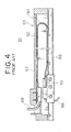
- FIG. 4 shows a conventional power supply apparatus ( JP,H11-342807,A ).
- the conventional power supply apparatus 61 is disposed in a sliding door of a motor vehicle.
- the power supply apparatus 61 includes an elongate case 63 for receiving a flat wire harness 62 folded in a U shape, a flexible reinforcing plate 64 disposed on an outer surface of the wire harness 62, a slider 65 disposed on a movable end of the wire harness 62, and a rail 66 slidably engaging with the slider 65.
- the reinforcing plate 64 is formed with a thin steel and is held by a magnetized wall 67 of the case 63 and holds the flat wire harness 62.
- the movable end of the flat wire harness 62 is connected to a wire harness 68 of a vehicle body at the slider 65 and a fixed end thereof is connected to a wire harness 69 of the sliding door.
- the slider 65 moves back and forth on the rail 66 as the sliding door is closed and opened.
- the flat wire harness 62 moves back and forth with the slider 65 and keeps the U shape to absorb a stroke of closing and opening of the sliding door. An electric power and signal are thereby supplied to auxiliary devices of the sliding door from the vehicle body.
- the conventional power supply apparatus 61 utilizes the flat wire harness 62 so that a number of circuitries and a current supplied are limited.
- the magnetized wall 67 for holding the steel reinforcing plate 64 has a complicated structure resulting to high cost.
- a power supply apparatus (not shown) utilizing a wire harness with a circular or oval section prevents drooping of the wire harness with a rigidity thereof.
- FIGS. 5-7 show a power supply apparatus 71 adapted to a long sliding door or long sliding seat of a motor vehicle.
- the power supply apparatus 71 has an elongate case 74 and a slider 73.
- a wire harness 72 disposed in the case 74 droops down and bends severalfold and stops the further movement of the slider 73.
- An object of the present invention is to provide a power supply apparatus for a long sliding structure, such as a long sliding door and long sliding seat, for enabling a smooth sliding operation without drooping and bending a wire harness.
- a power supply apparatus for long slide includes a case for receiving a wire harness folded back in a U shape; a slider slidably engaged with the case for holding a movable end of the wire harness; a pulley rotatably engaged with an inner surface of a turn-around portion (bent portion) of the wire harness; and a compression coil spring for urging the pulley in a direction opposite to a return direction of the wire harness.
- the pulley When the slider is positioned in a front end portion of the case and the compression coil spring is most compressed, the pulley is pressed toward a rear end portion of the case with urging force of the compression coil spring so that the wire harness is stretched with the pulley without drooping.
- an upper portion (forward portion) of the wire harness becomes shorter and a lower portion (return portion) thereof becomes longer.
- the compression coil spring resiliently urges the pulley toward the rear end portion of the case so that the upper portion of the wire harness is stretched between the slider and the pulley, and the lower portion thereof is stretched between the case and the pulley.
- the pulley rotates together with the wire harness with low friction responsive to expansion and contraction of the wire harness due to movement of the slider.
- the wire harness is always stretched rearward with the compression coil spring without drooping and bending during movement of the slider so that the slider can move smoothly rearward and forward without jamming.
- the pulley is rotatably connected with a support portion and the support portion is slidably engaged with the case and the compression coil spring is resiliently abutted on the support portion.
- the support portion is positioned with the case and slid along the case.
- One end of the compression coil spring resiliently abuts on the support portion without displacement so that the pulley moves rearward and forward in the case together with the support portion without displacement.
- the support portion has a support rod projecting therefrom, the support rod is inserted into one end of the compression coil spring, and the other end of thereof is received into a pair of guide walls when the compression coil spring is most compressed.
- the one end of the compression coil spring is supported with the support rod of the support portion and the other end thereof is stably supported with the pair of the guide walls.
- the pair of the guide walls are covered with a base wall and a cover of the case at both sides thereof to define a receiving chamber having a rectangular tube shape.
- the power supply apparatus further includes a circular shaped guide plate facing the pulley, wherein the turn-around portion is positioned between the pulley and the guide plate.
- the turn-around portion of the wire harness is interposed between the pulley and the guide plate and slidably engages therewith.
- the guide plate prevents separation of the wire harness from the pulley and keeps the bent portion contact with the pulley.
- the case has a narrow portion and a wide portion
- the wide portion has the pulley and the compression coil spring
- the movable end of the wire harness is positioned in the narrow portion when the compression coil spring is most compressed.
- an inner surface of the narrow portion of the wire harness supports the movable wire harness end. Cooperative operation of the compression coil spring and the inner surface of the narrow portion thereby prevents the drooping and bending of the wire harness, even when the movable wire harness end tends to droop or bend.
- the narrow portion and the wide portion expand the whole length of the case for easily achieving long slide of the wire harness.
- FIGS. 1-3 show an embodiment of a power supply apparatus for long slide of the present invention.
- the power supply apparatus 1 for long slide includes an elongate case 2, which has a narrow portion 2a and a wide portion 2b along a longitudinal direction thereof, a wire harness 3 with a circular or oval section, which is arranged in the case 2 and bent in a U or J shape, a slider 6 slidably disposed on the case 2, which holds one end (movable end) of the wire harness 3 and slides on the case 2 along the longitudinal direction of the case 2, a pulley 4 slidably engaging with an inner surface of a bent portion (turn-around portion) 3b of the wire harness 3 for holding the wire harness 3, and a compression coil spring 7 for resiliently urging the pulley 4 in a direction (extending direction of the wire harness 3) opposite to a return direction of the wire harness 3 to stretch the wire harness 3 in the case 2 without droop or bent thereof.
- the case 2 made of a synthetic resin or metal includes a main body 2 (same reference number as the case) and a plate shaped cover (not shown).
- the main body 2 includes the narrow portion 2a and the wide portion 2b intervened with a step portion 8.
- the narrow portion 2a is shorter than the wide portion 2b.
- the cover (not shown) covers a front opening of the main body 2 and is fastened to the main body 2 with a locking means or fastener.
- the main body 2 has a base wall 9, an upper wall 10, lower walls 11 and 12, a front wall 13, and a rear wall 14, upstanding from the base wall 9.
- the base wall 9 extends over the narrow and wide portions 2a and 2b.
- the base wall 9 and the cover each have a guide portion 17, elongate groove or bore, extending in a longitudinal direction thereof at the center of a width of the wide portion 2b.
- the guide portion 17 slidably supports a support portion 27 supporting the pulley 4.
- the upper wall 10 of the main body 2 has a slit-shaped guide portion 18 for slidably guiding the slider 6.
- a groove 19 formed at a midpoint of a height of the slider 6 slidably engages with the guide portion 18.
- An upper half portion of the slider 6 is exposed outside from the main body 2 and a lower half portion thereof is disposed inside the narrow portion 2a of the main body 2.
- the wire harness 3 is bent in a L shape at the slider 6 and forms a movable wire harness end 20, which passes through the slider 6 and is connected with a connector 21.
- the narrow portion 2a of the main body 2 has the lower wall 11 joined to the step portion 8, the front wall 13, and the upper wall 10.
- the wide portion 2b of the main body 2 has the lower wall 12, a front wall (step portion 8), the rear wall 14 (FIG. 2), the base wall 9, and the upper wall 10.
- the base wall 9 and the upper wall 10 extend over the narrow and wide portions 2a and 2b.
- the wire harness 3 extends from a front end to the pulley 4 along an inner surface of the upper wall 10, is turned around at an outer surface of the pulley 4, is arranged along an inner surface of the lower wall 12, and is led outside through an opening 22 of the step portion 8.
- the wire harness 3 has a corrugated tube 26 made of a synthetic resin for protecting a plurality of insulated electrical wires.
- the corrugated tube 26 has alternating annular ridges and grooves around the tube and is well flexible.
- a net tube is also possible for use in place of the corrugated tube 26 and the plurality of the electrical wires bound with a tape without the protection tube is also possible for use.
- the pulley 4 is made of a synthetic resin, and has circular disks at both sides and annular outer surface 4a.
- the pulley 4 has a diameter a little less than an inner width between the upper wall 10 and the lower wall 12 by twice of the diameter of the wire harness 3.
- a width of the outer surface 4a (thickness of the pulley) is almost same as the diameter of the wire harness 3.
- the outer surface 4a has a section of a circular groove to be engaged with the bent portion 3b of the wire harness 3 without displacement.
- the pulley 4 has a central axle 28 rotatably supported with a pair of connection plates 29, 30 disposed at both sides of the support portion 27.
- the support portion 27 has ribs 31 on outer surfaces of the connection plates 29 and 30. The ribs 31 slidably engage with the guide portions 17 of the case 2 and the cover (not shown) so as to position the support portion 27 and the pulley 4 in the center of the width of the main body 2.
- the one connection plate 29 facing to the base wall 9 is longer and wider than the other connection plate 30 facing to the cover.
- the one connection plate 29 has a circular guide plate 34 perpendicularly upstanding at a distal end thereof.
- the guide plate 34 is opposed to the outer surface 4a of the pulley 4 and slidably holds the bent portion 3b of the wire harness 3 with the pulley 4.
- the guide plate 34 always makes the bent portion 3b contact with the outer surface 4a of the pulley 4 for preventing displacement of the bent portion 3b of the wire harness 3 from the pulley 4.
- the pulley 4, the support portion 27, the connection plates 29 and 30, and the guide plate 34 form a harness support unit 35.
- a support rod 36 projects from a front end of the support portion 27 and is inserted into the compression coil spring 7 through a rear end 7b thereof.
- a front end 7a of the compression coil spring 7 resiliently abuts on the step portion 8 and the rear end 7b resiliently abuts on the support portion 27.
- a pair of parallel guide walls 37 extend inward from the step portion 8 along the base wall 9.
- An inner width between the guide walls 37 is a little larger than an outer diameter of the compression coil spring 7 and an outer diameter of the support rod 36 is a little smaller than an inner diameter of the compression coil spring 7.
- the support rod 36 has a length equal or less than a length of the most compressed coil spring 7 and approximately equal to the length of the pair of the guide walls 37.
- the compression coil spring 7 When the slider 6 is positioned close to the front wall 13, the compression coil spring 7 is most compressed in the pair of the guide walls 37.
- the most compressed coil spring 7 is received in a tube shaped chamber defined by the guide walls 37, the base wall 9, and the cover (not shown).
- the support potion 27 becomes adjacent to rear ends of the guide walls 37 and the pulley 4 is positioned less than a middle point of the length of the wide portion 2b with about the step portion 8.
- the compression coil spring 7 urges the wire harness 3 through the pulley 4 toward the rear wall 14 so that an upper portion 3a (forward portion) and a lower portion 3c (return portion) of the wire harness 3 are stretched along the upper wall 10 and the lower wall 12 of the case 2.
- a front half of the upper portion 3a is adjacent to the lower wall 11 of the narrow portion 2a so that the front half thereof is supported with the lower wall 11 without drooping.
- a length of the narrow portion 2a can be adjusted to any sliding length of the slider 6.
- the slider 6 moves rearward together with the upper portion 3a of the wire harness 3.
- the compression coil spring 7 expands gradually and concurrently urges the pulley 4 in a moving direction of the slider 6.
- the stretching force of the compression coil spring 7 stretches the upper portion 3a of the wire harness 3 without drooping so that the slider 6 smoothly moves without jamming.
- the support rod 36 separates from the guide walls 37 and moves together with the pulley 4.
- both the upper and lower portions 3a and 3c have almost the same length.
- the power supply apparatus 1 can be utilized when it is upside down.
- the compression coil spring 7 pushes rearward the pulley 4 and the pulley 6 pushes rearward the wire harness 3 so that the lower portion 3c (upper portion when upside down) is stretched without drooping.
- the upper portion 3a becomes shortest and the lower portion 3c becomes longest and extends along the lower wall 12 of the case 2.
- Both the guide plate 34 adjacent to the pulley 4 and the bent portion 3b of the wire harness 3 are positioned close to the rear wall 14 of the case 2.
- the compression coil spring 7 still stretches the lower portion 3c of the wire harness 3 by urging rearward the pulley 4 even when the slider 6 is positioned close to the rear wall 14.
- the upper portion 3a becomes longer and the compression coil spring urges the wire harness 3 through the pulley 4 in a direction opposite to the moving direction of the slider 6.
- the upper portion 3a and the lower portion 3c of the wire harness 3 are stretched without drooping when the slider 6 is positioned in the middle point of the power supply apparatus 1 so that the slider 6 smoothly moves without jamming.
- the bent portion 3b of the wire harness 3 and the pulley 4 move a half of the moving distance of the slider 6.
- the positions of the slider 6, the bent portion 3b, and the pulley 4 have a linear relation (proportional) among them. Contrary to this, the position of the center of the upper portion 3a in the wide portion 2b of the case 2, or the droopiest position, varies in a quadratic function manner.
- the compression coil spring 7 always stretches or urges the bent portion 3b of the wire harness 3 through the pulley 4 in the case 2 so that the droop or bent of the wire harness 3 is assuredly prevented.
- the drooping of the upper portion of the wire harness occurs when the power supply apparatus is mounted either vertically or horizontally so that the bending of the wire harness has a broad meaning including the drooping.
- FIGS. 1 and 3 show the sliding structure (not shown) such as the sliding door or sliding seat positioned at a forward end and rearward end, respectively.
- the movable wire harness end 20 led from the slider 6 is connected to the vehicle body through a step space and a harness 23 led from the case 2 is fixed to the sliding door and connected to a wire harness or auxiliary units.
- FIG. 1 shows the left side sliding door fully closed
- FIG. 2 shows an intermediate state
- FIG. 3 shows the sliding door fully opened.
- FIG. 1 shows the sliding seat in a front end position (or rear end position)
- FIG. 2 shows the sliding seat in the intermediate position
- FIG. 3 shows the sliding seat in the rear end position (or front end position).
- the long hole or long groove as the guide portion 18 for the slider 6 can be disposed on the base wall 9 and the cover instead of the upper wall 10 of the case 2, and a projection or a rib engaging with the guide portion 18 can be disposed on the slider 6.
- the movable wire harness end 20 can be led outside from the elongate guide portion 17 disposed on the cover or base wall 9 or from the guide portion 18 disposed on the upper wall 10 of the case 2.
- the guide plate 34 facing the pulley 4 can be replaced with a plurality of small rollers (not shown) circularly disposed.
- the narrow portion 2a of the front half of the case 2 can be the wide portion 2b and have the same lower wall as the wide portion 2b. In this instance, the opening 22 is disposed on the lower wall or the front wall. If the stroke of the sliding structure is a little shorter, the narrow portion 2a can be deleted and the only wide portion 2b is utilized for long slide.
- the compression coil spring always pushes the wire harness through the pulley in the direction opposite to the return direction of the wire harness and the wire harness is always stretched in the case without bending so that the sliding structure smoothly slides for long slide and provides a reliable power supply.
- the support portion properly positions the pulley and the compression coil spring in the case so that the wire harness is always resiliently urged.
- the sliding structure thereby smoothly slides for long slide and provides the reliable power supply.
- each end of the long compression coil spring responsive to long slide is supported with the support rod and the guide walls when the coil spring is stretched and compressed, respectively, so that the compression coil spring assuredly pushes the pulley.
- the sliding structure thereby smoothly slides for long slide and provides the reliable power supply.
- the urging force of the compression coil spring and the guide plate always keep the pulley contact with the wire harness even a fast slide operation so that the wire harness is stretched without drooping.
- the sliding structure thereby smoothly slides for long slide and provides the reliable power supply.
- the narrow portion of the case supports the wire harness therein so that the entire length of the case becomes longer and enable the power supply apparatus to slide long.
Abstract
An object of the present invention is to provide a smooth and secure sliding operation for a sliding structure for long slide without drooping and bending a wire harness. A power supply apparatus 1 for long slide includes a case 2 for receiving a wire harness 3 folded back in a U shape, a slider 6 slidably engaged with the case 2 for holding one end (movable end) of the wire harness 3, a pulley 4 rotatably engaged with an inner surface of a turn-around portion 3b of the wire harness 3, and a compression coil spring 7 for resiliently urging the pulley 4 in a direction opposite to a return direction of the wire harness. The pulley 4 is rotatably connected with a support portion 27 and the support portion 27 is slidably engaged with the case 2 and a compression coil spring 7 is resiliently abutted on the support portion. A support rod 36 is inserted into one end of the compression coil spring 7 and the other end of thereof is received into a pair of guide walls 37. The support rod is positioned inside the guide walls when the compression coil spring is most compressed.
Description
- The present invention relates to a power supply apparatus disposed in a long sliding structure such as a sliding door or sliding seat of a motor vehicle. The power supply apparatus receives a long wire harness folded in a U shape to prevent bending of the long wire harness.
- FIG. 4 shows a conventional power supply apparatus (
JP,H11-342807,A - The conventional
power supply apparatus 61 is disposed in a sliding door of a motor vehicle. Thepower supply apparatus 61 includes anelongate case 63 for receiving aflat wire harness 62 folded in a U shape, aflexible reinforcing plate 64 disposed on an outer surface of thewire harness 62, aslider 65 disposed on a movable end of thewire harness 62, and arail 66 slidably engaging with theslider 65. - The reinforcing
plate 64 is formed with a thin steel and is held by amagnetized wall 67 of thecase 63 and holds theflat wire harness 62. The movable end of theflat wire harness 62 is connected to awire harness 68 of a vehicle body at theslider 65 and a fixed end thereof is connected to awire harness 69 of the sliding door. - The
slider 65 moves back and forth on therail 66 as the sliding door is closed and opened. Theflat wire harness 62 moves back and forth with theslider 65 and keeps the U shape to absorb a stroke of closing and opening of the sliding door. An electric power and signal are thereby supplied to auxiliary devices of the sliding door from the vehicle body. - The conventional
power supply apparatus 61 utilizes theflat wire harness 62 so that a number of circuitries and a current supplied are limited. Themagnetized wall 67 for holding thesteel reinforcing plate 64 has a complicated structure resulting to high cost. - It is disclosed that a power supply apparatus (not shown) utilizing a wire harness with a circular or oval section prevents drooping of the wire harness with a rigidity thereof.
- The power supply apparatus is adapted to a short slide stroke but not to a long slide stroke. FIGS. 5-7 show a
power supply apparatus 71 adapted to a long sliding door or long sliding seat of a motor vehicle. Thepower supply apparatus 71 has anelongate case 74 and aslider 73. As shown in FIGS. 6 and 7, as a sliding structure such as the sliding door and sliding seat moves, awire harness 72 disposed in thecase 74 droops down and bends severalfold and stops the further movement of theslider 73. - An object of the present invention is to provide a power supply apparatus for a long sliding structure, such as a long sliding door and long sliding seat, for enabling a smooth sliding operation without drooping and bending a wire harness.
- According to a first object of the present invention, a power supply apparatus for long slide includes a case for receiving a wire harness folded back in a U shape; a slider slidably engaged with the case for holding a movable end of the wire harness; a pulley rotatably engaged with an inner surface of a turn-around portion (bent portion) of the wire harness; and a compression coil spring for urging the pulley in a direction opposite to a return direction of the wire harness.
- When the slider is positioned in a front end portion of the case and the compression coil spring is most compressed, the pulley is pressed toward a rear end portion of the case with urging force of the compression coil spring so that the wire harness is stretched with the pulley without drooping. As the sliding structure is moved rearward with a sliding operation, an upper portion (forward portion) of the wire harness becomes shorter and a lower portion (return portion) thereof becomes longer. The compression coil spring resiliently urges the pulley toward the rear end portion of the case so that the upper portion of the wire harness is stretched between the slider and the pulley, and the lower portion thereof is stretched between the case and the pulley. The pulley rotates together with the wire harness with low friction responsive to expansion and contraction of the wire harness due to movement of the slider. The wire harness is always stretched rearward with the compression coil spring without drooping and bending during movement of the slider so that the slider can move smoothly rearward and forward without jamming.
- Preferably, the pulley is rotatably connected with a support portion and the support portion is slidably engaged with the case and the compression coil spring is resiliently abutted on the support portion.
- Accordingly, the support portion is positioned with the case and slid along the case. One end of the compression coil spring resiliently abuts on the support portion without displacement so that the pulley moves rearward and forward in the case together with the support portion without displacement.
- Preferably, the support portion has a support rod projecting therefrom, the support rod is inserted into one end of the compression coil spring, and the other end of thereof is received into a pair of guide walls when the compression coil spring is most compressed.
- Thereby, the one end of the compression coil spring is supported with the support rod of the support portion and the other end thereof is stably supported with the pair of the guide walls. The pair of the guide walls are covered with a base wall and a cover of the case at both sides thereof to define a receiving chamber having a rectangular tube shape. When the slider is positioned in a front end portion of the case, and the compression coil spring is most compressed and received in the pair of the guide walls, the support rod is positioned in the compression coil spring and the guide walls. The compression coil spring stretches as the slider moves rearward and most stretches at a rear end portion of the case. The support rod stably positions the one end of the compression coil spring during stretching and the pair of the guide walls hold and position the other end of the compression coil spring.
- Preferably, the power supply apparatus further includes a circular shaped guide plate facing the pulley, wherein the turn-around portion is positioned between the pulley and the guide plate.
- Accordingly, the turn-around portion of the wire harness is interposed between the pulley and the guide plate and slidably engages therewith. The guide plate prevents separation of the wire harness from the pulley and keeps the bent portion contact with the pulley.
- Preferably, the case has a narrow portion and a wide portion, the wide portion has the pulley and the compression coil spring, and the movable end of the wire harness is positioned in the narrow portion when the compression coil spring is most compressed.
- Accordingly, an inner surface of the narrow portion of the wire harness supports the movable wire harness end. Cooperative operation of the compression coil spring and the inner surface of the narrow portion thereby prevents the drooping and bending of the wire harness, even when the movable wire harness end tends to droop or bend. The narrow portion and the wide portion expand the whole length of the case for easily achieving long slide of the wire harness.
-
- FIG. 1 shows a perspective view of an embodiment of a power supply apparatus for long slide of the present invention with a slider positioned close to a front wall of a case;
- FIG. 2 shows a perspective view of the power supply apparatus with the slider positioned in a middle point of the case;
- FIG. 3 shows the power supply apparatus with the slider positioned close to a rear wall of the case;
- FIG. 4 is a sectional view of an embodiment of a conventional power supply apparatus;
- FIG. 5 is a perspective view of a conventional power supply apparatus for long slide;
- FIG. 6 is a perspective view showing a problem of the conventional power supply apparatus for long slide; and
- FIG. 7 is a perspective view showing a problem of the conventional power supply apparatus for long slide.
- FIGS. 1-3 show an embodiment of a power supply apparatus for long slide of the present invention.
- The
power supply apparatus 1 for long slide includes anelongate case 2, which has anarrow portion 2a and awide portion 2b along a longitudinal direction thereof, awire harness 3 with a circular or oval section, which is arranged in thecase 2 and bent in a U or J shape, aslider 6 slidably disposed on thecase 2, which holds one end (movable end) of thewire harness 3 and slides on thecase 2 along the longitudinal direction of thecase 2, apulley 4 slidably engaging with an inner surface of a bent portion (turn-around portion) 3b of thewire harness 3 for holding thewire harness 3, and acompression coil spring 7 for resiliently urging thepulley 4 in a direction (extending direction of the wire harness 3) opposite to a return direction of thewire harness 3 to stretch thewire harness 3 in thecase 2 without droop or bent thereof. - The
case 2 made of a synthetic resin or metal includes a main body 2 (same reference number as the case) and a plate shaped cover (not shown). Themain body 2 includes thenarrow portion 2a and thewide portion 2b intervened with a step portion 8. Thenarrow portion 2a is shorter than thewide portion 2b. The cover (not shown) covers a front opening of themain body 2 and is fastened to themain body 2 with a locking means or fastener. - The
main body 2 has a base wall 9, anupper wall 10,lower walls front wall 13, and arear wall 14, upstanding from the base wall 9. The base wall 9 extends over the narrow andwide portions guide portion 17, elongate groove or bore, extending in a longitudinal direction thereof at the center of a width of thewide portion 2b. Theguide portion 17 slidably supports asupport portion 27 supporting thepulley 4. - As shown in FIG. 1, the
upper wall 10 of themain body 2 has a slit-shaped guide portion 18 for slidably guiding theslider 6. Agroove 19 formed at a midpoint of a height of theslider 6 slidably engages with theguide portion 18. An upper half portion of theslider 6 is exposed outside from themain body 2 and a lower half portion thereof is disposed inside thenarrow portion 2a of themain body 2. Thewire harness 3 is bent in a L shape at theslider 6 and forms a movablewire harness end 20, which passes through theslider 6 and is connected with aconnector 21. The meanings of upper, lower, front, and rear of the specification do not necessary mean the direction of thepower supply apparatus 1 in use. - The
narrow portion 2a of themain body 2 has thelower wall 11 joined to the step portion 8, thefront wall 13, and theupper wall 10. Thewide portion 2b of themain body 2 has thelower wall 12, a front wall (step portion 8), the rear wall 14 (FIG. 2), the base wall 9, and theupper wall 10. The base wall 9 and theupper wall 10 extend over the narrow andwide portions - As seen in FIG. 1, when the
slider 6 is positioned close to thefront wall 13, thewire harness 3 extends from a front end to thepulley 4 along an inner surface of theupper wall 10, is turned around at an outer surface of thepulley 4, is arranged along an inner surface of thelower wall 12, and is led outside through anopening 22 of the step portion 8. - The
wire harness 3 has a corrugatedtube 26 made of a synthetic resin for protecting a plurality of insulated electrical wires. Thecorrugated tube 26 has alternating annular ridges and grooves around the tube and is well flexible. A net tube is also possible for use in place of thecorrugated tube 26 and the plurality of the electrical wires bound with a tape without the protection tube is also possible for use. - The
pulley 4 is made of a synthetic resin, and has circular disks at both sides and annularouter surface 4a. Thepulley 4 has a diameter a little less than an inner width between theupper wall 10 and thelower wall 12 by twice of the diameter of thewire harness 3. A width of theouter surface 4a (thickness of the pulley) is almost same as the diameter of thewire harness 3. Theouter surface 4a has a section of a circular groove to be engaged with thebent portion 3b of thewire harness 3 without displacement. - The
pulley 4 has acentral axle 28 rotatably supported with a pair ofconnection plates support portion 27. Thesupport portion 27 hasribs 31 on outer surfaces of theconnection plates ribs 31 slidably engage with theguide portions 17 of thecase 2 and the cover (not shown) so as to position thesupport portion 27 and thepulley 4 in the center of the width of themain body 2. - The one
connection plate 29 facing to the base wall 9 is longer and wider than theother connection plate 30 facing to the cover. The oneconnection plate 29 has acircular guide plate 34 perpendicularly upstanding at a distal end thereof. Theguide plate 34 is opposed to theouter surface 4a of thepulley 4 and slidably holds thebent portion 3b of thewire harness 3 with thepulley 4. Theguide plate 34 always makes thebent portion 3b contact with theouter surface 4a of thepulley 4 for preventing displacement of thebent portion 3b of thewire harness 3 from thepulley 4. Thepulley 4, thesupport portion 27, theconnection plates guide plate 34 form aharness support unit 35. - A
support rod 36 projects from a front end of thesupport portion 27 and is inserted into thecompression coil spring 7 through arear end 7b thereof. Afront end 7a of thecompression coil spring 7 resiliently abuts on the step portion 8 and therear end 7b resiliently abuts on thesupport portion 27. - A pair of
parallel guide walls 37 extend inward from the step portion 8 along the base wall 9. An inner width between theguide walls 37 is a little larger than an outer diameter of thecompression coil spring 7 and an outer diameter of thesupport rod 36 is a little smaller than an inner diameter of thecompression coil spring 7. When thecompression coil spring 7 is most compressed, thesupport rod 36 is received between the pair of theguide walls 37, as shown in FIG. 1. Thesupport rod 36 has a length equal or less than a length of the mostcompressed coil spring 7 and approximately equal to the length of the pair of theguide walls 37. - When the
slider 6 is positioned close to thefront wall 13, thecompression coil spring 7 is most compressed in the pair of theguide walls 37. The mostcompressed coil spring 7 is received in a tube shaped chamber defined by theguide walls 37, the base wall 9, and the cover (not shown). Thesupport potion 27 becomes adjacent to rear ends of theguide walls 37 and thepulley 4 is positioned less than a middle point of the length of thewide portion 2b with about the step portion 8. Thecompression coil spring 7 urges thewire harness 3 through thepulley 4 toward therear wall 14 so that an upper portion 3a (forward portion) and alower portion 3c (return portion) of thewire harness 3 are stretched along theupper wall 10 and thelower wall 12 of thecase 2. - A front half of the upper portion 3a is adjacent to the
lower wall 11 of thenarrow portion 2a so that the front half thereof is supported with thelower wall 11 without drooping. A length of thenarrow portion 2a can be adjusted to any sliding length of theslider 6. - When a sliding structure (not shown) such as a sliding door or sliding seat is slid, the
slider 6 moves rearward together with the upper portion 3a of thewire harness 3. Thecompression coil spring 7 expands gradually and concurrently urges thepulley 4 in a moving direction of theslider 6. The stretching force of thecompression coil spring 7 stretches the upper portion 3a of thewire harness 3 without drooping so that theslider 6 smoothly moves without jamming. As thecompression coil spring 7 stretches, thesupport rod 36 separates from theguide walls 37 and moves together with thepulley 4. - As the upper portion 3a of the
wire harness 3 further moves rearward, thelower portion 3c thereof is gradually extended such that thelower portion 3c is stretched rearward through thepulley 4 with the urging force (stretching force) of thecompression coil spring 7. When the slider moves to the step portion 8 of thecase 2, both the upper andlower portions 3a and 3c have almost the same length. - As clearly seen from FIGS. 2 and 3, the
power supply apparatus 1 can be utilized when it is upside down. Thecompression coil spring 7 pushes rearward thepulley 4 and thepulley 6 pushes rearward thewire harness 3 so that thelower portion 3c (upper portion when upside down) is stretched without drooping. - When the
slider 6 reaches close to therear wall 14 as seen in FIG. 3, the upper portion 3a becomes shortest and thelower portion 3c becomes longest and extends along thelower wall 12 of thecase 2. Both theguide plate 34 adjacent to thepulley 4 and thebent portion 3b of thewire harness 3 are positioned close to therear wall 14 of thecase 2. Thecompression coil spring 7 still stretches thelower portion 3c of thewire harness 3 by urging rearward thepulley 4 even when theslider 6 is positioned close to therear wall 14. - When the
slider 6 is moved in a reverse direction (forward direction) from the position of FIG. 3, the upper portion 3a becomes longer and the compression coil spring urges thewire harness 3 through thepulley 4 in a direction opposite to the moving direction of theslider 6. The upper portion 3a and thelower portion 3c of thewire harness 3 are stretched without drooping when theslider 6 is positioned in the middle point of thepower supply apparatus 1 so that theslider 6 smoothly moves without jamming. - The
bent portion 3b of thewire harness 3 and thepulley 4 move a half of the moving distance of theslider 6. The positions of theslider 6, thebent portion 3b, and thepulley 4 have a linear relation (proportional) among them. Contrary to this, the position of the center of the upper portion 3a in thewide portion 2b of thecase 2, or the droopiest position, varies in a quadratic function manner. Thecompression coil spring 7 always stretches or urges thebent portion 3b of thewire harness 3 through thepulley 4 in thecase 2 so that the droop or bent of thewire harness 3 is assuredly prevented. - It is noticed that the drooping of the upper portion of the wire harness occurs when the power supply apparatus is mounted either vertically or horizontally so that the bending of the wire harness has a broad meaning including the drooping.
- FIGS. 1 and 3 show the sliding structure (not shown) such as the sliding door or sliding seat positioned at a forward end and rearward end, respectively. When the
power supply apparatus 1 is mounted vertically in the sliding door, the movablewire harness end 20 led from theslider 6 is connected to the vehicle body through a step space and aharness 23 led from thecase 2 is fixed to the sliding door and connected to a wire harness or auxiliary units. FIG. 1 shows the left side sliding door fully closed, FIG. 2 shows an intermediate state, and FIG. 3 shows the sliding door fully opened. - When the
power supply apparatus 1 is adopted to the sliding seat and disposed on a floor panel of the vehicle body, the movablewire harness end 20 led from theslider 6 is connected to a wire harness or auxiliary units of the sliding seat and theharness 23 led from thecase 2 is connected to the wire harness of the vehicle body. FIG. 1 shows the sliding seat in a front end position (or rear end position), FIG. 2 shows the sliding seat in the intermediate position, and FIG. 3 shows the sliding seat in the rear end position (or front end position). When thepower supply apparatus 1 is horizontally mounted to the vehicle body, the movablewire harness end 20 led from theslider 6 is arranged in the sliding seat by bending in a direction of a thickness of the case 2 (upward direction). - In the above embodiment, the long hole or long groove as the
guide portion 18 for theslider 6 can be disposed on the base wall 9 and the cover instead of theupper wall 10 of thecase 2, and a projection or a rib engaging with theguide portion 18 can be disposed on theslider 6. The movablewire harness end 20 can be led outside from theelongate guide portion 17 disposed on the cover or base wall 9 or from theguide portion 18 disposed on theupper wall 10 of thecase 2. Theguide plate 34 facing thepulley 4 can be replaced with a plurality of small rollers (not shown) circularly disposed. - The
narrow portion 2a of the front half of thecase 2 can be thewide portion 2b and have the same lower wall as thewide portion 2b. In this instance, theopening 22 is disposed on the lower wall or the front wall. If the stroke of the sliding structure is a little shorter, thenarrow portion 2a can be deleted and the onlywide portion 2b is utilized for long slide. - According to the present invention, the compression coil spring always pushes the wire harness through the pulley in the direction opposite to the return direction of the wire harness and the wire harness is always stretched in the case without bending so that the sliding structure smoothly slides for long slide and provides a reliable power supply.
- According to the present invention, the support portion properly positions the pulley and the compression coil spring in the case so that the wire harness is always resiliently urged. The sliding structure thereby smoothly slides for long slide and provides the reliable power supply.
- According to the present invention, each end of the long compression coil spring responsive to long slide is supported with the support rod and the guide walls when the coil spring is stretched and compressed, respectively, so that the compression coil spring assuredly pushes the pulley. The sliding structure thereby smoothly slides for long slide and provides the reliable power supply.
- According to the present invention, the urging force of the compression coil spring and the guide plate always keep the pulley contact with the wire harness even a fast slide operation so that the wire harness is stretched without drooping. The sliding structure thereby smoothly slides for long slide and provides the reliable power supply.
- According to the present invention, the narrow portion of the case supports the wire harness therein so that the entire length of the case becomes longer and enable the power supply apparatus to slide long.
Claims (5)
- A power supply apparatus for long slide comprising:a case for receiving a wire harness folded back in a U shape;a slider slidably engaged with the case for holding a movable end of the wire harness;a pulley rotatably engaged with an inner surface of a turn-around portion of the wire harness; anda compression coil spring for urging the pulley in a direction opposite to a return direction of the wire harness.
- The power supply apparatus as claimed in claim 1, wherein the pulley is rotatably connected with a support portion and the support portion is slidably engaged with the case and the compression coil spring is resiliently abutted on the support portion.
- The power supply apparatus as claimed in claim 2, wherein the support portion has a support rod projecting therefrom, the support rod being inserted into one end of the compression coil spring, the other end thereof being received into a pair of guide walls when the compression coil spring is most compressed.
- The power supply apparatus as claimed in any one of claims 1-3, further comprising a circular shaped guide plate facing the pulley, wherein the turn-around portion of the wire harness is positioned between the pulley and the guide plate.
- The power supply apparatus as claimed in any one of claims 1-4, wherein the case has a narrow portion and a wide portion, the wide portion having the pulley and the compression coil spring, the movable end of the wire harness being positioned in the narrow portion when the compression coil spring is most compressed.
Applications Claiming Priority (2)
| Application Number | Priority Date | Filing Date | Title |
|---|---|---|---|
| JP2004230590A JP2006050841A (en) | 2004-08-06 | 2004-08-06 | Power supply device for long slide |
| PCT/JP2005/014193 WO2006013885A1 (en) | 2004-08-06 | 2005-08-03 | Electric power supply device for long slide |
Publications (2)
| Publication Number | Publication Date |
|---|---|
| EP1783875A1 true EP1783875A1 (en) | 2007-05-09 |
| EP1783875A4 EP1783875A4 (en) | 2009-04-22 |
Family
ID=35787166
Family Applications (1)
| Application Number | Title | Priority Date | Filing Date |
|---|---|---|---|
| EP05768595A Withdrawn EP1783875A4 (en) | 2004-08-06 | 2005-08-03 | Electric power supply device for long slide |
Country Status (4)
| Country | Link |
|---|---|
| US (1) | US20090035953A1 (en) |
| EP (1) | EP1783875A4 (en) |
| JP (1) | JP2006050841A (en) |
| WO (1) | WO2006013885A1 (en) |
Cited By (6)
| Publication number | Priority date | Publication date | Assignee | Title |
|---|---|---|---|---|
| US7683259B2 (en) | 2008-01-31 | 2010-03-23 | Yazaki Corporation | Power supply system |
| CN112002471A (en) * | 2020-08-21 | 2020-11-27 | 安徽天康集团数据线缆有限公司 | High-speed data transmission cable |
| WO2021110291A1 (en) * | 2019-12-02 | 2021-06-10 | Self Electronics Co., Ltd. | Waterproof power supply track with cable retracting mechanism |
| DE102017207981B4 (en) | 2016-05-13 | 2022-05-25 | Eds - Electric Drive Solution Gmbh & Co. Kg | Cable bridge device and cable bridge arrangement |
| WO2023105428A1 (en) * | 2021-12-07 | 2023-06-15 | Adient Us Llc | Cable-deflecting device and seat longitudinal adjustment apparatus having a cable deflecting device |
| WO2023232784A1 (en) * | 2022-05-31 | 2023-12-07 | Kostal Automobil Elektrik Gmbh & Co. Kg | Device for providing an electrically conductive connection between two contact points which can be moved linearly relative to each other |
Families Citing this family (17)
| Publication number | Priority date | Publication date | Assignee | Title |
|---|---|---|---|---|
| WO2008015935A1 (en) * | 2006-07-31 | 2008-02-07 | The Furukawa Electric Co., Ltd. | Electricity supply device for sliding door |
| DE102008024277B4 (en) | 2007-06-29 | 2010-11-18 | Yazaki Corp. | Power supply system |
| JP5450933B2 (en) | 2007-06-29 | 2014-03-26 | 矢崎総業株式会社 | Corrugated tube |
| JP4913690B2 (en) * | 2007-07-27 | 2012-04-11 | 古河電気工業株式会社 | Power supply device for sliding door |
| CN102216121B (en) * | 2008-12-16 | 2013-10-16 | 矢崎总业株式会社 | Harness cabling device |
| JP5286063B2 (en) * | 2008-12-16 | 2013-09-11 | 矢崎総業株式会社 | Slide device |
| US8684418B2 (en) * | 2011-05-04 | 2014-04-01 | GM Global Technology Operations LLC | Flexible dress package for an end-effector employed with a robotic arm |
| JP2015219961A (en) * | 2014-05-14 | 2015-12-07 | ミック電子工業株式会社 | Power feeding rail |
| KR200490004Y1 (en) * | 2015-11-17 | 2019-09-10 | 한국조선해양 주식회사 | Guiding device for cable |
| JP6836393B2 (en) * | 2016-12-28 | 2021-03-03 | 矢崎総業株式会社 | Arrangement structure for sliding doors |
| JP6901914B2 (en) * | 2017-06-26 | 2021-07-14 | 日本発條株式会社 | Power supply and vehicle seats |
| JP6772997B2 (en) * | 2017-09-29 | 2020-10-21 | 株式会社オートネットワーク技術研究所 | Wire harness routing device |
| KR102507945B1 (en) * | 2018-03-26 | 2023-03-09 | 후루카와 덴키 고교 가부시키가이샤 | Flat cable routing structure for cable retractor and slide seat |
| US10731807B1 (en) * | 2018-07-23 | 2020-08-04 | Graham Holloway | Electrical connection device and lighting system for a sectional door |
| CN113453958A (en) * | 2019-03-28 | 2021-09-28 | 古河电气工业株式会社 | Cable arrangement structure |
| FR3114057B1 (en) * | 2020-09-15 | 2022-12-02 | Faurecia Sieges Dautomobile | Electrical cable guide device for motor vehicle seat rail |
| CN112490962B (en) * | 2020-11-09 | 2022-03-11 | 临沂矿业集团有限责任公司 | Coal-winning machine cable protection device |
Citations (5)
| Publication number | Priority date | Publication date | Assignee | Title |
|---|---|---|---|---|
| JPH07237826A (en) * | 1994-02-24 | 1995-09-12 | Daido Steel Co Ltd | Cord storing device |
| JP2003220901A (en) * | 2002-01-28 | 2003-08-05 | Sumitomo Wiring Syst Ltd | Wire harness wiring structure of slide door for automobile |
| JP2003306089A (en) * | 2002-04-11 | 2003-10-28 | Yazaki Corp | Cable extra length absorbing device and power supply device for slide door using the absorbing device |
| JP2003312385A (en) * | 2002-04-24 | 2003-11-06 | Yazaki Corp | Electric wire excessive length absorption device and slide door power feeder using it |
| US20040017648A1 (en) * | 2002-07-25 | 2004-01-29 | Yazaki Corporation | Power-supply wiring device and harness layout structure by the power-supply wiring device |
Family Cites Families (3)
| Publication number | Priority date | Publication date | Assignee | Title |
|---|---|---|---|---|
| JP3954802B2 (en) * | 2000-04-11 | 2007-08-08 | 矢崎総業株式会社 | Power supply device for automotive sliding door |
| JP2003032866A (en) * | 2001-07-12 | 2003-01-31 | Yazaki Corp | Flat wiring harness and apparatu for storing its excessive length |
| JP4263684B2 (en) * | 2004-08-06 | 2009-05-13 | 矢崎総業株式会社 | Power supply device for slide |
-
2004
- 2004-08-06 JP JP2004230590A patent/JP2006050841A/en not_active Abandoned
-
2005
- 2005-08-03 WO PCT/JP2005/014193 patent/WO2006013885A1/en active Application Filing
- 2005-08-03 EP EP05768595A patent/EP1783875A4/en not_active Withdrawn
- 2005-08-03 US US11/659,232 patent/US20090035953A1/en not_active Abandoned
Patent Citations (5)
| Publication number | Priority date | Publication date | Assignee | Title |
|---|---|---|---|---|
| JPH07237826A (en) * | 1994-02-24 | 1995-09-12 | Daido Steel Co Ltd | Cord storing device |
| JP2003220901A (en) * | 2002-01-28 | 2003-08-05 | Sumitomo Wiring Syst Ltd | Wire harness wiring structure of slide door for automobile |
| JP2003306089A (en) * | 2002-04-11 | 2003-10-28 | Yazaki Corp | Cable extra length absorbing device and power supply device for slide door using the absorbing device |
| JP2003312385A (en) * | 2002-04-24 | 2003-11-06 | Yazaki Corp | Electric wire excessive length absorption device and slide door power feeder using it |
| US20040017648A1 (en) * | 2002-07-25 | 2004-01-29 | Yazaki Corporation | Power-supply wiring device and harness layout structure by the power-supply wiring device |
Non-Patent Citations (1)
| Title |
|---|
| See also references of WO2006013885A1 * |
Cited By (7)
| Publication number | Priority date | Publication date | Assignee | Title |
|---|---|---|---|---|
| US7683259B2 (en) | 2008-01-31 | 2010-03-23 | Yazaki Corporation | Power supply system |
| DE102017207981B4 (en) | 2016-05-13 | 2022-05-25 | Eds - Electric Drive Solution Gmbh & Co. Kg | Cable bridge device and cable bridge arrangement |
| WO2021110291A1 (en) * | 2019-12-02 | 2021-06-10 | Self Electronics Co., Ltd. | Waterproof power supply track with cable retracting mechanism |
| CN112002471A (en) * | 2020-08-21 | 2020-11-27 | 安徽天康集团数据线缆有限公司 | High-speed data transmission cable |
| CN112002471B (en) * | 2020-08-21 | 2021-11-26 | 安徽天康集团数据线缆有限公司 | High-speed data transmission cable |
| WO2023105428A1 (en) * | 2021-12-07 | 2023-06-15 | Adient Us Llc | Cable-deflecting device and seat longitudinal adjustment apparatus having a cable deflecting device |
| WO2023232784A1 (en) * | 2022-05-31 | 2023-12-07 | Kostal Automobil Elektrik Gmbh & Co. Kg | Device for providing an electrically conductive connection between two contact points which can be moved linearly relative to each other |
Also Published As
| Publication number | Publication date |
|---|---|
| US20090035953A1 (en) | 2009-02-05 |
| JP2006050841A (en) | 2006-02-16 |
| WO2006013885A1 (en) | 2006-02-09 |
| EP1783875A4 (en) | 2009-04-22 |
Similar Documents
| Publication | Publication Date | Title |
|---|---|---|
| EP1783875A1 (en) | Electric power supply device for long slide | |
| US7238029B2 (en) | Power-supply device | |
| US7252541B2 (en) | Structure for receiving and supporting a folded wiring harness | |
| EP1783874A1 (en) | Electric supply device for long slide | |
| US7220129B1 (en) | Electric supply device for slide structure | |
| US6603076B2 (en) | Power supply structure in sliding structure | |
| US7151224B2 (en) | Continuous electric power-supplying device | |
| JP5074757B2 (en) | Power feeding device and harness wiring structure using the same | |
| US7265294B2 (en) | Feeder and harness wiring structure using same | |
| US8686286B2 (en) | Electrical wire routing device | |
| US9670708B2 (en) | Wire harness routing structure | |
| JP4175825B2 (en) | Power supply device for sliding door | |
| JP5197171B2 (en) | Power supply device | |
| JP2012045994A (en) | Slide wiring device | |
| US7641260B2 (en) | Power supply apparatus for sliding door | |
| US7534959B2 (en) | Power supply device | |
| JP2008167558A (en) | Electric supply device | |
| JP2004051058A (en) | Harness protector and feeding structure using it | |
| CN105939003B (en) | Wire harness laying structure | |
| JP3908992B2 (en) | Power feeding device and harness wiring structure using the same | |
| CN113423611B (en) | Cable arrangement structure | |
| JP2004112984A (en) | Feeding device and harness wiring structure using the device | |
| JP2010028987A (en) | Power feeding device and harness routing structure using the same | |
| JP2001061223A (en) | Electric wire storing device | |
| JP2008017545A (en) | Regular power-supply device |
Legal Events
| Date | Code | Title | Description |
|---|---|---|---|
| PUAI | Public reference made under article 153(3) epc to a published international application that has entered the european phase |
Free format text: ORIGINAL CODE: 0009012 |
|
| 17P | Request for examination filed |
Effective date: 20070206 |
|
| AK | Designated contracting states |
Kind code of ref document: A1 Designated state(s): DE FR |
|
| DAX | Request for extension of the european patent (deleted) | ||
| RBV | Designated contracting states (corrected) |
Designated state(s): DE FR |
|
| A4 | Supplementary search report drawn up and despatched |
Effective date: 20090323 |
|
| 17Q | First examination report despatched |
Effective date: 20090807 |
|
| STAA | Information on the status of an ep patent application or granted ep patent |
Free format text: STATUS: THE APPLICATION IS DEEMED TO BE WITHDRAWN |
|
| 18D | Application deemed to be withdrawn |
Effective date: 20091218 |