EP1783371B1 - Electric pump unit - Google Patents
Electric pump unit Download PDFInfo
- Publication number
- EP1783371B1 EP1783371B1 EP06291732A EP06291732A EP1783371B1 EP 1783371 B1 EP1783371 B1 EP 1783371B1 EP 06291732 A EP06291732 A EP 06291732A EP 06291732 A EP06291732 A EP 06291732A EP 1783371 B1 EP1783371 B1 EP 1783371B1
- Authority
- EP
- European Patent Office
- Prior art keywords
- pumps
- pump unit
- electric pump
- manifold
- motors
- Prior art date
- Legal status (The legal status is an assumption and is not a legal conclusion. Google has not performed a legal analysis and makes no representation as to the accuracy of the status listed.)
- Active
Links
Images


Classifications
-
- F—MECHANICAL ENGINEERING; LIGHTING; HEATING; WEAPONS; BLASTING
- F04—POSITIVE - DISPLACEMENT MACHINES FOR LIQUIDS; PUMPS FOR LIQUIDS OR ELASTIC FLUIDS
- F04C—ROTARY-PISTON, OR OSCILLATING-PISTON, POSITIVE-DISPLACEMENT MACHINES FOR LIQUIDS; ROTARY-PISTON, OR OSCILLATING-PISTON, POSITIVE-DISPLACEMENT PUMPS
- F04C11/00—Combinations of two or more machines or pumps, each being of rotary-piston or oscillating-piston type; Pumping installations
- F04C11/001—Combinations of two or more machines or pumps, each being of rotary-piston or oscillating-piston type; Pumping installations of similar working principle
-
- F—MECHANICAL ENGINEERING; LIGHTING; HEATING; WEAPONS; BLASTING
- F04—POSITIVE - DISPLACEMENT MACHINES FOR LIQUIDS; PUMPS FOR LIQUIDS OR ELASTIC FLUIDS
- F04C—ROTARY-PISTON, OR OSCILLATING-PISTON, POSITIVE-DISPLACEMENT MACHINES FOR LIQUIDS; ROTARY-PISTON, OR OSCILLATING-PISTON, POSITIVE-DISPLACEMENT PUMPS
- F04C2/00—Rotary-piston machines or pumps
- F04C2/08—Rotary-piston machines or pumps of intermeshing-engagement type, i.e. with engagement of co-operating members similar to that of toothed gearing
- F04C2/10—Rotary-piston machines or pumps of intermeshing-engagement type, i.e. with engagement of co-operating members similar to that of toothed gearing of internal-axis type with the outer member having more teeth or tooth-equivalents, e.g. rollers, than the inner member
-
- F—MECHANICAL ENGINEERING; LIGHTING; HEATING; WEAPONS; BLASTING
- F04—POSITIVE - DISPLACEMENT MACHINES FOR LIQUIDS; PUMPS FOR LIQUIDS OR ELASTIC FLUIDS
- F04C—ROTARY-PISTON, OR OSCILLATING-PISTON, POSITIVE-DISPLACEMENT MACHINES FOR LIQUIDS; ROTARY-PISTON, OR OSCILLATING-PISTON, POSITIVE-DISPLACEMENT PUMPS
- F04C2/00—Rotary-piston machines or pumps
- F04C2/08—Rotary-piston machines or pumps of intermeshing-engagement type, i.e. with engagement of co-operating members similar to that of toothed gearing
- F04C2/12—Rotary-piston machines or pumps of intermeshing-engagement type, i.e. with engagement of co-operating members similar to that of toothed gearing of other than internal-axis type
- F04C2/14—Rotary-piston machines or pumps of intermeshing-engagement type, i.e. with engagement of co-operating members similar to that of toothed gearing of other than internal-axis type with toothed rotary pistons
- F04C2/18—Rotary-piston machines or pumps of intermeshing-engagement type, i.e. with engagement of co-operating members similar to that of toothed gearing of other than internal-axis type with toothed rotary pistons with similar tooth forms
Definitions
- the invention relates to an electric pump unit, of the type comprising two hydraulic pumps, in particular geared, driven in rotation by a motor device as described in JP 07-243393 disclosing the preamble of claim 1.
- Electro-pumps of this type which are known and in particular used by the power steering of a motor vehicle, have the major disadvantage that the power of the group is limited although the vehicles to be equipped with a power steering are becoming heavier and the powers necessary to ensure the power steering are higher and higher.
- the power of the electric pump units is limited for technological reasons, in particular because the power supply and the connectors do not accept a sufficient intensity, as the technology of high power engines (> 1.5 kW ) is almost non-existent for a voltage of 12V and that the development of such motors is limited to low series and has a high cost.
- the invention aims to overcome the drawback of known systems.
- the electro-pump unit according to the invention is characterized in that it comprises two hydraulic pumps and two electric motors which are arranged so that the power of the group can be obtained by adding the powers of the two. engines.
- the electropump is characterized in that it comprises a discharge manifold which comprises a discharge channel common to both pumps.
- the electric pump unit is characterized in that the two pumps are integrated in a common pump body.
- the electro-pump unit is characterized in that comprises a suction manifold having a suction channel common to both pumps.
- the electric pump unit is characterized in that the pump body is sandwiched between the suction manifold and the discharge manifold, each manifold bearing on its outer face one of the two motors.
- the electric pump unit is characterized in that the pump body comprises, inside an outer casing wall, a high pressure volume common to the two pumps, which communicates with the working chambers of the two pumps and a common high pressure volume provided in the discharge manifold, which is in communication with the common discharge channel.
- the electro-pump unit is characterized in that at least one of the pumps comprises, in its discharge path a non-return valve so that this pump can be selectively stopped.
- the electric pump unit is characterized in that it comprises an engine control device adapted to control one engine from the outside and that engine controls the speed of the other.
- the electric pump unit is characterized in that the two motors rotate in the same direction or in opposite directions.
- the electro-pump unit is characterized in that the two pumps are adapted to rotate with an angular offset of a few degrees to provide a decrease in the pressure pulsations produced by the electro-pump unit.
- the electric pump unit is characterized in that the two pumps are capable of operating in phase opposition.
- the electric pump unit is characterized in that the pumps operate at different speeds of rotation.
- the electric pump unit is characterized in that the presence of two motors constitutes a redundancy security means.
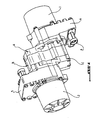
- the figure 1 is the overview of an electric pump unit according to the invention, which comprises two electric motors and two hydraulic pumps, each driven by one of the two motors.
- references 1 and 2 designate the two electric motors
- the reference B the pump body which encloses two hydraulic gear pumps, A manifold inlet or suction pumps and C the manifold outlet or discharge.
- the pump body B is sandwiched between the inlet manifolds A and outlet C.
- Each motor has a base portion respectively 4 and 5 which carries the electrical connections 6 of the motors and encloses the electrical circuits.
- the figure 15 gives the synoptic diagram of the system according to the figure 1 .
- the engine 1 drives a first pump designated by the reference 8 and the second the engine 2 a second pump 9.
- the two pumps 8 and 9 draw the hydraulic fluid into a reservoir 10.
- the discharge paths of the two pumps are met at the junction point 14 and thus supply the user with high-pressure hydraulic fluid, generally in oil.
- a check valve 12 In the discharge line of each pump upstream of the junction point 14 is provided a check valve 12.
- a pressure limiter 11 and a feed valve 13 are mounted in parallel between the junction point 14 and the reservoir.
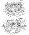
- the figure 3 illustrates the structure of the suction manifold A and also shows the gears of the gear trains of the two pumps 8 and 9, noted for the pump 8 and 16 for the pump 9, the gears being shown with their lower bearings 17 and higher 18.
- the presentation of the manifold or suction support A is supplemented by the two views in section 6 and 7 which are taken along the lines VI-VI and VII-VII indicated on the figure 2 .
- the suction manifold A has a suction channel 20 which opens out into the side face 21.
- This channel 20 which is straight as seen on the Figures 6 and 7 communicates with low pressure capacitive cavities 23, 24 dug in the manifold from the inner face 25 intended to receive the pump body B.
- This suction channel 20 is connected to a reservoir 10 according to Figure 19, outside the group electro-pump.
- the cavity 23 near the pinions 16 of the pump 9 is wider and deeper than the cavity 24 on the side of the other pump, which is in the form of an arcuate groove.
- the cavity 23 has a raised bottom intermediate zone 23 'which delimits a cavity 26 for receiving the spring 27 of the pressure limiter 11 (FIG. 19).
- the suction channel 20 opens directly into the cavity 23 and communicates with the cavity 24 by a vertical channel 28, that is to say perpendicular to the section plane.
- the figure 7 further indicates at 30 grooves in which are placed unrepresented seals.
- the reference 25 designates the installation face of the pump body B.
- the figures 4 , 8 and 9 show that the pump body B has a bottom wall 32 which rests on the installation face 25 of the suction manifold A and on which rises an outer casing wall 33, and inside this casing there are presqu'Ilots 35, 36 which delimit chambers 37, 38 for housing the gear trains 15, 16 and bearings 17, 18, parts in the form of peduncles 39 for attaching the presqu'Ilots to the envelope wall 33 configured for producing two cylindrical housings 40, 41 of the two nonreturn valves 12 ( figure 15 ) and the housing 39 in alignment with the cavity 26 for receiving the pressure limiter 11 (Figure 19).
- the envelope wall 33 has a boss which delimits a cavity 43 intended to receive the feedback valve 13 ( figure 15 ).
- the remainder of the space inside the envelope wall 33 constitutes a capacitive volume comprising four cavities 45, 46, 47, 48 separated from each other only by the peduncle-shaped portions and two narrow ribs 49 of attachment of the penlets to the envelope wall.
- the front face and the surfaces of the presqu'Ilots, peduncles and ribs constitute the exposure face 34 for manifold C.
- FIG. 8 and 9 show the inlet channels 50 and 51 of the chambers 37 and 38 for housing the gear trains with the bearings of the two pumps and the outlet channels 53 and 54.
- the inlet channel 51 communicates with the low pressure cavity 23 into which the suction channel 20 opens.
- the inlet channel 50 is connected to the suction channel 20 in a corresponding manner, not shown specifically.
- the figure 12 also shows that the outlet channel 54 communicates with the housing 41 of one of the two check valves 12, through the orifice 52 of the seat of the ball 55 of the valve.
- the ball 55 is pushed back onto its seat by a return spring 57 resting at its other end on a bearing base 58 being guided by a member in the form of a rod 59 of the valve, disposed in the center of the housing 41.
- the outlet channel 53 communicates in the same way with the housing 40 of the other non-return valve 12.
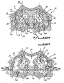
- FIG. 5 and the sectional views of Figures 10 and 11 illustrate the structure of the manifold or pressure support C.
- the discharge manifold C comprises a bottom wall 60 on which is raised perpendicularly an outer casing wall 61 which encloses a common capacitive volume 63.
- the front face 62 of this wall is intended to bear on the front face of installation of the pump body 34.
- the volume 63 surrounds two islands 65, 66 for supporting the upper bearings 18 of the two gear trains, these islands are connected to each other by a relatively thin bar 67 and, at the of this bar, to the casing wall 61 by a raised area 68.
- This area has two circular projections 69 to the level of the laying plane of the manifold. These zones 69 are intended to serve as a bearing surface, each at the base of a base 58 of spring support of a nonreturn valve 12.
- housing cavities 40, 41 of the pump body B communicate with the volume 63 of the discharge manifold C, by passages indicated at 72 on either side and around the projections 69 for supporting the anti-backflow valves. -return.
- the sectional view of the figure 10 shows that the capacitive volume 63 is in communication with a high pressure outlet channel 75 which opens out into the side wall 76 of the discharge manifold C.
- a high pressure outlet channel 75 which opens out into the side wall 76 of the discharge manifold C.
- the opening towards the outside of the outlet channel that is to say of repression, is not visible, but one recognizes at the bottom of the volume 63 in 77 the opening of the channel 75 in the volume 63.
- the discharge outlet manifold C comes, in the assembled state, by its upper face 62 bearing on the upper face 34 of the pump body B, the cavities 45, 46, 47 and 48 of the body B and the volume 63 of the discharge manifold C constitute a single volume filled with the high-pressure oil discharged by the pumps 8 and 9 through the discharge channels 53 and 54 ( figure 9 ) through the check valves 12 arranged in the chambers 40, 41.
- the pressure limiter 11 ( figure 15 ) it is placed in the cavity 26 of the suction manifold A ( figures 3 , 6, 7 ) and the cavity 39 of the pump body B ( figures 4 , 8, 9 ).
- the bottom of the cavity 26 is in communication with the low pressure suction space 23, by a not shown channel and the cavity 39 of the pump body B communicates via a visible channel 75 Figures 8 and 9 with the high pressure cavity 48 and thus with the discharge channel 75 via the volume 63 of the discharge manifold C.
- the refilling valve 13 it is housed in the cavity 43 of the pump body B ( figures 4 , 8, 9 ) that communicates, as we see on the figure 13 with the low-pressure groove 24 of the suction manifold A on the one hand and the volume 63 of the discharge manifold C on the other hand.
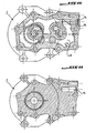
- the two motors 1 and 2 are arranged on either side of the assembly formed by the two pumps and comprising the suction manifolds A and discharge C and sandwiched between these two manifolds , the pump body B.
- the driving shaft of the motor 2 which is intended to pass through the bore 81 visible in the island 66 of the delivery manifold C, is represented at 80.
- Concerning the drive of the gear train 15 of the pump 8, it is driven by the engine 1 whose shaft will then cross the bottom wall of the suction manifold A.
- the invention therefore consists in using two motors which are controlled to be able to add the available powers of the two pumps.
- the invention also makes it possible to drive two different and uncoupled pumps to increase the difference between the minimum and maximum flow of the electropump. Pumps are generally limited in minimum flow because it is necessary to operate them at a minimum speed, the use of two pumps and two motors allows during low flow requests, not operate a motor and reduce power consumption. Thanks to the presence of a non-return valve at the outlet of the pumps, one of the two pumps can be stopped.
- the invention makes it possible to use engines that are widely used in series and to provide redundancy between the two motors, which makes it possible to avoid stopping power assistance in the event of a failure of one of the engines.
- the engine control it is performed from the instructions of the vehicle that the electro-pump group team.
- the steering could be provided by one of the two engines which would then drive the speed of the second.
- each pump generates pulsations of a frequency equal to the number of teeth multiplied by the rotation frequency of the pump.
- the motor control could be carried out to obtain a functioning of the pumps in opposition of phase. We could also drive the engines at different speeds.
- the invention makes it possible, by integrating the functions of the two pumps into a common pump body, to reduce the size of the group, while providing a large common high pressure volume, which provides, despite the presence of two pump units, a considerable improvement in damping pulsations produced by these pumps.
Description
L'invention concerne un groupe électro-pompe, du type comprenant deux pompes hydrauliques, notamment à engrenage, entraînées en rotation par un dispositif moteur tel que décrit dans
Des groupes électro-pompes de ce type, qui sont connus et notamment utilisés par la direction assistée de véhicule automobile, présentent l'inconvénient majeur que la puissance du groupe est limitée bien que les véhicules à équiper d'une direction assistée sont de plus en plus lourds et les puissances nécessaires pour assurer la direction assistée sont de plus en plus élevées. Or, actuellement la puissance moteur des groupes électro-pompe est limitée pour des raisons technologiques, notamment du fait que l'alimentation et la connectique n'acceptent pas une intensité suffisante, que la technologie des moteurs de forte puissance (> 1,5 kW) est quasi inexistante pour une tension de 12V et que le développement de tels moteurs se limite à des faibles séries et présente un coût élevé.Electro-pumps of this type, which are known and in particular used by the power steering of a motor vehicle, have the major disadvantage that the power of the group is limited although the vehicles to be equipped with a power steering are becoming heavier and the powers necessary to ensure the power steering are higher and higher. However, currently the power of the electric pump units is limited for technological reasons, in particular because the power supply and the connectors do not accept a sufficient intensity, as the technology of high power engines (> 1.5 kW ) is almost non-existent for a voltage of 12V and that the development of such motors is limited to low series and has a high cost.
L'invention a pour but de pallier l'inconvénient des systèmes connus.The invention aims to overcome the drawback of known systems.
Pour atteindre ce but, le groupe électro-pompe selon l'invention est caractérisé en ce qu'il comprend deux pompes hydrauliques et deux moteurs électriques qui sont agencés de façon à ce que la puissance du groupe puisse être obtenue par additionnement des puissances des deux moteurs.To achieve this goal, the electro-pump unit according to the invention is characterized in that it comprises two hydraulic pumps and two electric motors which are arranged so that the power of the group can be obtained by adding the powers of the two. engines.
Selon l'invention, le groupe électro-pompe est caractérisé en ce qu'il comprend un manifold de refoulement qui comporte un canal de refoulement commun aux deux pompes.According to the invention, the electropump is characterized in that it comprises a discharge manifold which comprises a discharge channel common to both pumps.
Toujours selon l'invention, le groupe électro-pompe est caractérisé en ce que les deux pompes sont intégrées à un corps de pompe commun.Still according to the invention, the electric pump unit is characterized in that the two pumps are integrated in a common pump body.
Encore selon l'invention, le groupe électro-pompe est caractérisé en ce qu'il comprend un manifold d'aspiration comportant un canal d'aspiration commun aux deux pompes.Still according to the invention, the electro-pump unit is characterized in that comprises a suction manifold having a suction channel common to both pumps.
Enfin, selon l'invention, le groupe électro-pompe est caractérisé en ce que le corps de pompe est disposé en sandwich entre le manifold d'aspiration et le manifold de refoulement, chaque manifold portant sur sa face extérieure un des deux moteurs.Finally, according to the invention, the electric pump unit is characterized in that the pump body is sandwiched between the suction manifold and the discharge manifold, each manifold bearing on its outer face one of the two motors.
Selon une autre caractéristique de l'invention, le groupe électro-pompe est caractérisé en ce que le corps de pompe comporte, à l'intérieur d'une paroi d'enveloppe extérieure un volume haute pression commun aux deux pompes, qui communique avec les chambres de travail des deux pompes et un volume haute pression commun prévu dans le manifold de refoulement, qui est en communication avec le canal de refoulement commun.According to another characteristic of the invention, the electric pump unit is characterized in that the pump body comprises, inside an outer casing wall, a high pressure volume common to the two pumps, which communicates with the working chambers of the two pumps and a common high pressure volume provided in the discharge manifold, which is in communication with the common discharge channel.
Selon encore une autre caractéristique de l'invention, le groupe électro-pompe est caractérisé en ce qu'au moins une des pompes comporte, dans sa voie de refoulement un clapet anti-retour si bien que cette pompe puisse être arrêtée sélectivement.According to yet another characteristic of the invention, the electro-pump unit is characterized in that at least one of the pumps comprises, in its discharge path a non-return valve so that this pump can be selectively stopped.
Selon encore une autre caractéristique de l'invention, le groupe électro-pompe est caractérisé en ce qu'il comprend un dispositif de pilotage des moteurs adapté pour assurer le pilotage d'un moteur de l'extérieur et en ce que ce moteur pilote la vitesse de l'autre.According to yet another characteristic of the invention, the electric pump unit is characterized in that it comprises an engine control device adapted to control one engine from the outside and that engine controls the speed of the other.
Selon encore une autre caractéristique de l'invention, le groupe électro-pompe est caractérisé en ce que les deux moteurs tournent dans le même sens ou dans les sens opposés.According to yet another characteristic of the invention, the electric pump unit is characterized in that the two motors rotate in the same direction or in opposite directions.
Selon encore une autre caractéristique de l'invention, le groupe électro-pompe est caractérisé en ce que les deux pompes sont adaptées pour tourner avec un décalage angulaire de quelques degrés pour procurer une diminution des pulsations de pression produites par le groupe électro-pompe.According to yet another characteristic of the invention, the electro-pump unit is characterized in that the two pumps are adapted to rotate with an angular offset of a few degrees to provide a decrease in the pressure pulsations produced by the electro-pump unit.
Selon encore une autre caractéristique de l'invention, le groupe électro-pompe est caractérisé en ce que les deux pompes sont susceptibles de fonctionner en opposition de phases.According to yet another characteristic of the invention, the electric pump unit is characterized in that the two pumps are capable of operating in phase opposition.
Selon encore une autre caractéristique de l'invention, le groupe électro-pompe est caractérisé en ce que les pompes fonctionnent à des vitesses de rotation différentes.According to yet another characteristic of the invention, the electric pump unit is characterized in that the pumps operate at different speeds of rotation.
Selon encore une autre caractéristique de l'invention, le groupe électro-pompe est caractérisé en ce que la présence de deux moteurs constitue un moyen de sécurité par redondance.According to yet another characteristic of the invention, the electric pump unit is characterized in that the presence of two motors constitutes a redundancy security means.
L'invention sera mieux comprise, et d'autres buts, caractéristiques, détails et avantages de celle-ci apparaîtront plus clairement dans la description explicative qui va suivre faite en référence aux dessins schématiques annexés donnés uniquement à titre d'exemple illustrant deux modes de réalisation de l'invention et dans lesquels :
- la
figure 1 est une vue en perspective d'un premier mode de réalisation d'un système de groupe électro-pompe selon l'invention ; - la
figure 2 est une vue latérale du système représenté sur lafigure 1 , - la
figure 3 est une vue en perspective du manifold d'aspiration indiqué en A sur lafigure 1 du système selon l'invention, certaines parties du module pompe étant représentés supplémentairement ; - la
figure 4 est une vue en perspective du corps de pompe B de lafigure 1 , disposé sur le module d'aspiration A ; - la
figure 5 est une vue en perspective du manifold de refoulement indiqué en C sur lafigure 1 ; - la
figure 6 est une vue en coupe le long de la ligne VI-VI de lafigure 2 ; - la
figure 7 est une vue en coupe le long de la ligne VII-VII de lafigure 2 ; - la
figure 8 est une vue en coupe selon la ligne VIII-VIII de lafigure 2 ; - la
figure 9 est une vue en coupe selon la ligne IX-IX de lafigure 2 ; - la
figure 10 est une vue en coupe selon la ligne X-X de lafigure 2 ; - la
figure 11 est une vue en coupe selon la ligne XI-XI de lafigure 2 ; - la
figure 12 est une vue en coupe de l'ensemble formé par le corps de pompe B et des manifolds A et C à l'état assemblé selon la ligne XII-XII de lafigure 8 ; - la
figure 13 est une vue en coupe de cet ensemble selon la ligne XIII-XIII desfigures 8 et 9 ; - la
figure 14 est une vue en coupe de cet même ensemble selon la ligne XIV-XIV desfigures 5 et9 ;et - la
figure 15 donne le schéma synoptique du système selon l'invention, comportant deux moteurs électriques d'entraînement de deux pompes hydrauliques.
- the
figure 1 is a perspective view of a first embodiment of an electro-pump system according to the invention; - the
figure 2 is a side view of the system shown on thefigure 1 , - the
figure 3 is a perspective view of the suction manifold indicated in A on thefigure 1 of the system according to the invention, some parts of the pump module being represented additionally; - the
figure 4 is a perspective view of the pump body B of thefigure 1 , arranged on the suction module A; - the
figure 5 is a perspective view of the discharge manifold indicated in C on thefigure 1 ; - the
figure 6 is a sectional view along the line VI-VI of thefigure 2 ; - the
figure 7 is a sectional view along line VII-VII of thefigure 2 ; - the
figure 8 is a sectional view along line VIII-VIII of thefigure 2 ; - the
figure 9 is a sectional view along the line IX-IX of thefigure 2 ; - the
figure 10 is a sectional view along line XX of thefigure 2 ; - the
figure 11 is a sectional view along the line XI-XI of thefigure 2 ; - the
figure 12 is a sectional view of the assembly formed by the pump body B and manifolds A and C in the assembled state along the line XII-XII of thefigure 8 ; - the
figure 13 is a sectional view of this set along line XIII-XIII ofFigures 8 and 9 ; - the
figure 14 is a sectional view of this same ensemble according to line XIV-XIV offigures 5 and9 ;and - the
figure 15 gives the block diagram of the system according to the invention, comprising two electric motors for driving two hydraulic pumps.
La
La
En se reportant aux
La
Le manifold d'aspiration A comporte un canal d'aspiration 20 qui débouche à l'extérieur dans la face latérale 21. Ce canal 20 qui est rectiligne comme on le voit sur les
On constate que la cavité 23 à proximité des pignons 16 de la pompe 9 est plus large et plus profonde que la cavité 24 du côté de l'autre pompe, qui est réalisé sous forme d'une rainure arquée. La cavité 23 présente une zone intermédiaire à fond surélevé 23' qui délimite une cavité 26 de réception du ressort 27 du limiteur de pression 11 (figure 19). Le canal d'aspiration 20 débouche directement dans la cavité 23 et communique avec la cavité 24 par un canal vertical 28, c'est-à-dire perpendiculaire au plan de coupe. La
Il ressort des
Les
Les vues en coupe parallèles au plan du corps de pompe des
La
La figure en perspective 5 et les vues en coupe des
Le manifold de refoulement C comporte une paroi de fond 60 sur laquelle s'élève perpendiculairement une paroi extérieure d'enveloppe 61 qui enferme un volume capacitif commun 63. La face frontale 62 de cette paroi est destinée à venir en appui sur la face frontale de pose du corps de pompe 34. Le volume 63 entoure deux îlots 65, 66 de support des paliers supérieurs 18 des deux trains d'engrenage, ces îlots sont reliés l'un à l'autre par une barrette relativement mince 67 et, au niveau de cette barrette, à la paroi d'enveloppe 61 par une zone surélevée 68. De cette zone s'élève deux saillies circulaires 69 jusqu'au niveau du plan de pose du manifold. Ces zones 69 sont destinées à servir de surface d'appui, chacune à la base d'un socle 58 d'appui de ressort d'un clapet anti-retour 12. Celles-ci sont isolées si bien que ces portions et la zone surélevée 68 rétrécissent, mais n'empêchent pas que l'huile remplissant la cavité puisse passer par-dessus la zone 68 en s'écoulant autour des saillies 69. On constate encore en 70 des gorges dans la face libre des îlots 65, 66 pour la réception de joints de compensation à coeur qui entourent les zones de support des paliers 18 des trains d'engrenage, les parties 73 en creux étant remplies de l'huile basse pression de lubrification. A l'état assemblé du corps de pompe B et des manifolds A et C, les îlots 65 et 66 du manifold C sont en appui sur les presqu'îlots 35, 36 du corps de pompe B.The discharge manifold C comprises a
En se reportant aux vues en coupe perpendiculaires, des
La vue en coupe de la
Etant donné que le manifold de sortie de refoulement C vient, à l'état assemblé, par sa face supérieure 62 en appui sur la face supérieure 34 du corps de pompe B, les cavités 45, 46, 47 et 48 du corps B et le volume 63 du manifold de refoulement C constituent un seul volume rempli de l'huile haute pression refoulé par les pompes 8 et 9 par les canaux de refoulement 53 et 54 (
Concernant le limiteur de pression 11 (
En ce qui concerne la soupape de réalimentation 13, elle est logée dans la cavité 43 du corps de pompe B (
Dans ce mode de réalisation, les deux moteurs 1 et 2 sont disposés de part et d'autre de l'ensemble formé par les deux pompes et comprenant les manifolds d'aspiration A et de refoulement C et, disposé en sandwich entre ces deux manifolds, le corps de pompe B. Sur la
Il ressort de la description de l'invention et des figures, que celle-ci résout le problème d'augmentation de la puissance d'un système électro-pompe tout en utilisant les technologies connues. L'invention consiste donc à utiliser deux moteurs qui sont pilotés pour pouvoir additionner les puissances disponibles des deux pompes. L'invention permet également en entraînant deux pompes différentes et non couplées d'augmenter la différence entre le débit minimum et maximum du groupe électro-pompe. Les pompes étant généralement limitées en débit minimum du fait qu'il est nécessaire de les faire fonctionner sous un régime minimum, l'utilisation de deux pompes et de deux moteurs permet lors de faibles demandes de débit, de ne faire fonctionner qu'un moteur et de diminuer la consommation de courant. Grâce à la présence d'un clapet anti-retour à la sortie des pompes, l'une des deux pompes peut être arrêtée. L'invention permet d'utiliser des moteurs largement utilisés en série et d'assurer une redondance entre les deux moteurs, ce qui permet d'éviter l'arrêt d'assistance à la conduite en cas de panne d'un des moteurs.It is apparent from the description of the invention and the figures, that it solves the problem of increasing the power of an electro-pump system while using the known technologies. The invention therefore consists in using two motors which are controlled to be able to add the available powers of the two pumps. The invention also makes it possible to drive two different and uncoupled pumps to increase the difference between the minimum and maximum flow of the electropump. Pumps are generally limited in minimum flow because it is necessary to operate them at a minimum speed, the use of two pumps and two motors allows during low flow requests, not operate a motor and reduce power consumption. Thanks to the presence of a non-return valve at the outlet of the pumps, one of the two pumps can be stopped. The invention makes it possible to use engines that are widely used in series and to provide redundancy between the two motors, which makes it possible to avoid stopping power assistance in the event of a failure of one of the engines.
Concernant le pilotage des moteurs, celui-ci est effectué à partir de consignes du véhicule que le groupe électro-pompe équipe. Le pilotage pourrait être assuré par un des deux moteurs qui piloterait alors la vitesse du second.Regarding the engine control, it is performed from the instructions of the vehicle that the electro-pump group team. The steering could be provided by one of the two engines which would then drive the speed of the second.
A l'avantage indiqué plus haut de la réduction du bruit et des pulsations hydrauliques grâce au grand volume de l'espace haute pression, s'ajoute que le bruit et les pulsations peuvent encore être réduits grâce à la coopération des deux pompes. En effet, chaque pompe génère des pulsations d'une fréquence égale au nombre de dents multiplié par la fréquence de rotation de la pompe. En faisant que les deux pompes tournent avec un calage de quelques degrés, il se produit une diminution des pulsations de pression, en même temps qu'une augmentation de la fréquence. Selon l'invention le pilotage moteur pourrait être effectué pour obtenir un fonctionnement des pompes en opposition de phase. On pourrait également piloter les moteurs à des vitesses différentes.To the advantage indicated above of the reduction of the noise and the hydraulic pulsations thanks to the large volume of the high-pressure space, is added that the noise and the pulsations can be further reduced thanks to the cooperation of the two pumps. Indeed, each pump generates pulsations of a frequency equal to the number of teeth multiplied by the rotation frequency of the pump. By making the two pumps turn with a setting of a few degrees, there is a decrease in the pressure pulsations, at the same time as an increase in the frequency. According to the invention the motor control could be carried out to obtain a functioning of the pumps in opposition of phase. We could also drive the engines at different speeds.
Il ressort de la description du mode de réalisation de l'invention, qui n'a été donné qu'à titre d'exemple, que l'invention permet, par une intégration des fonctions des deux pompes à un corps de pompe commun, de réduire l'encombrement du groupe, tout en prévoyant un volume haute pression commun important, qui apporte, malgré la présence de deux unités de pompe, une amélioration considérable de l'amortissement des pulsations produites par ces pompes.It emerges from the description of the embodiment of the invention, which has been given by way of example only, that the invention makes it possible, by integrating the functions of the two pumps into a common pump body, to reduce the size of the group, while providing a large common high pressure volume, which provides, despite the presence of two pump units, a considerable improvement in damping pulsations produced by these pumps.
Claims (9)
- An electric pump unit, of the type comprising two hydraulic pumps (8, 9), in particular gear pumps, and two electric motors (1, 2) driving the pumps, characterized in that the pumps (8, 9) are arranged so that the power of the unit can be obtained by adding the powers of both motors, that both pumps (8, 9) are incorporated into a shared pump body (B) and that the electric pump unit comprises a delivery manifold (C, 3) provided with a delivery channel (75) shared by both pumps (8, 9), and a suction manifold (A) comprising a suction channel (20) shared by both pumps, and in that the pump body (B) is sandwiched between the suction manifold (A) and the delivery manifold (C), each manifold carrying on the external face thereof one of the two motors.
- The electric pump unit according to claim 1, characterized in that the pump body (B) comprises within an exterior casing wall (33) a high pressure volume shared by both pumps and communicating with the compressed air chamber of both pumps, and a shared high pressure volume provided in the delivery manifold (C) and communicating with the shared delivery channel (75).
- The electric pump unit according to any of claims 1 or 2, characterized in that at least one of the pumps comprises, in the delivery path thereof, a check valve (12) so that this pump can be stopped selectively.
- The electric pump unit according to any of claims 1 to 3, characterized in that it comprises a device for driving the motors (1, 2), adapted to ensure driving of one motor externally, and in that this motor drives the speed of the other one.
- The electric pump unit according to any of claims 1 to 4, characterized in that both motors are running in the same direction or in opposite directions.
- The electric pump unit according to any of claims 1 to 5, characterized in that both pumps (8, 9) are adapted for running with an angular offset of several degrees in order to provide a decrease of pressure pulsations generated by the electric pump unit.
- The electric pump unit according to any of claims 1 to 6, characterized in that both pumps (8, 9) can operate in phase opposition.
- The electric pump unit according to any of claims 1 to 7, characterized in that the pumps operate at different rotational speeds.
- The electric pump unit according to any of claims 1 to 8, characterized in that the availability of two motors (1, 2) is a safety measure by redundancy.
Applications Claiming Priority (1)
| Application Number | Priority Date | Filing Date | Title |
|---|---|---|---|
| FR0511333A FR2893092B1 (en) | 2005-11-08 | 2005-11-08 | ELECTRO-PUMP GROUP, OF THE TYPE COMPRISING AT LEAST ONE HYDRAULIC PUMP, IN PARTICULAR A GEAR, DRIVEN IN ROTATION BY A MOTOR DEVICE |
Publications (2)
| Publication Number | Publication Date |
|---|---|
| EP1783371A1 EP1783371A1 (en) | 2007-05-09 |
| EP1783371B1 true EP1783371B1 (en) | 2009-08-05 |
Family
ID=36726582
Family Applications (1)
| Application Number | Title | Priority Date | Filing Date |
|---|---|---|---|
| EP06291732A Active EP1783371B1 (en) | 2005-11-08 | 2006-11-07 | Electric pump unit |
Country Status (4)
| Country | Link |
|---|---|
| US (1) | US7942649B2 (en) |
| EP (1) | EP1783371B1 (en) |
| DE (1) | DE602006008244D1 (en) |
| FR (1) | FR2893092B1 (en) |
Families Citing this family (15)
| Publication number | Priority date | Publication date | Assignee | Title |
|---|---|---|---|---|
| JP6137780B2 (en) * | 2012-04-26 | 2017-05-31 | 株式会社Ihiエアロスペース | Fluid supply device |
| US9115720B2 (en) | 2012-05-04 | 2015-08-25 | Ghsp, Inc. | Dual pump and motor with control device |
| US9562534B2 (en) | 2012-05-04 | 2017-02-07 | Ghsp, Inc. | In-line dual pump and motor with control device |
| US9752590B2 (en) | 2013-03-13 | 2017-09-05 | Ghsp, Inc. | Two pump design with coplanar interface surface |
| US10087927B2 (en) | 2014-05-01 | 2018-10-02 | Ghsp, Inc. | Electric motor with flux collector |
| US11015585B2 (en) | 2014-05-01 | 2021-05-25 | Ghsp, Inc. | Submersible pump assembly |
| FR3041045B1 (en) * | 2015-09-16 | 2020-11-27 | Jtekt Hpi | ARRANGEMENT OF AT LEAST TWO HYDRAULIC PUMP DEVICES |
| DE102016107447A1 (en) * | 2016-04-21 | 2017-11-09 | Schwäbische Hüttenwerke Automotive GmbH | Rotary pump with lubrication groove in the sealing bar |
| DE102016113366A1 (en) * | 2016-07-20 | 2018-01-25 | Weber-Hydraulik Gmbh | hydraulic power unit |
| DE102017208373A1 (en) * | 2017-05-18 | 2018-11-22 | Continental Teves Ag & Co. Ohg | Pressure delivery arrangement and corresponding method and use |
| JP6594381B2 (en) * | 2017-08-10 | 2019-10-23 | 本田技研工業株式会社 | Hydraulic control device |
| US10557480B1 (en) * | 2018-12-06 | 2020-02-11 | Razmik David Gharakhanian | Pumping systems and methods |
| DE102019111980A1 (en) | 2019-05-08 | 2020-11-12 | Rapa Automotive Gmbh & Co. Kg | POWER SUPPLY UNIT FOR ACTIVE SUSPENSION SYSTEM |
| DE102019118384A1 (en) | 2019-07-08 | 2021-01-14 | Rapa Automotive Gmbh & Co. Kg | MPE AXLE SET WITH A COMMON ECU |
| EP3865658B1 (en) * | 2020-02-13 | 2023-12-20 | Entecnia Consulting, S.L. | Flange connection for vacuum pumps |
Family Cites Families (12)
| Publication number | Priority date | Publication date | Assignee | Title |
|---|---|---|---|---|
| US2811930A (en) * | 1952-06-18 | 1957-11-05 | Borg Warner | Air motor governor |
| US2812715A (en) * | 1954-06-23 | 1957-11-12 | Westinghouse Electric Corp | Fuel system |
| DE1808411C3 (en) * | 1968-11-12 | 1973-08-16 | Jochen Dipl Ing Oplaender | PUMP UNIT OF TWO CENTRIFUGAL PUMPS ARRANGED IN A HOUSING |
| DD136759A1 (en) * | 1978-05-29 | 1979-07-25 | Hans Spengler | HIGH PRESSURE PUMPS UNIT |
| DE4021410A1 (en) * | 1990-07-06 | 1992-01-16 | Oplaender Wilo Werk Gmbh | DOUBLE CENTRIFUGAL PUMP |
| US5388761A (en) * | 1993-10-01 | 1995-02-14 | Langeman; Gary D. | Plural component delivery system |
| JPH07243393A (en) * | 1994-03-01 | 1995-09-19 | Ebara Corp | Pump unit |
| JPH07243392A (en) * | 1994-03-01 | 1995-09-19 | Ebara Corp | Pump unit |
| US6726465B2 (en) * | 1996-03-22 | 2004-04-27 | Rodney J. Groleau | Injection molding machine employing a flow path gear pump and method of use |
| FR2789446B1 (en) | 1999-02-04 | 2002-03-08 | Hydroperfect Internat Hpi | HYDRAULIC PUMP OF THE GEAR TYPE AND ELECTRIC PUMP GROUP EQUIPPED WITH SUCH A PUMP |
| DE10020162C2 (en) * | 2000-04-25 | 2002-04-25 | Hennecke Gmbh | Method and device for producing a flowable reaction mixture that forms a solid or foam |
| US7517200B2 (en) * | 2004-06-24 | 2009-04-14 | Caterpillar Inc. | Variable discharge fuel pump |
-
2005
- 2005-11-08 FR FR0511333A patent/FR2893092B1/en not_active Expired - Fee Related
-
2006
- 2006-11-07 DE DE602006008244T patent/DE602006008244D1/en active Active
- 2006-11-07 US US11/593,749 patent/US7942649B2/en active Active
- 2006-11-07 EP EP06291732A patent/EP1783371B1/en active Active
Also Published As
| Publication number | Publication date |
|---|---|
| EP1783371A1 (en) | 2007-05-09 |
| US7942649B2 (en) | 2011-05-17 |
| FR2893092A1 (en) | 2007-05-11 |
| US20070122298A1 (en) | 2007-05-31 |
| FR2893092B1 (en) | 2008-10-10 |
| DE602006008244D1 (en) | 2009-09-17 |
Similar Documents
| Publication | Publication Date | Title |
|---|---|---|
| EP1783371B1 (en) | Electric pump unit | |
| EP2486262B1 (en) | Circuit for supplying fuel to an aircraft engine | |
| FR2887921A1 (en) | OIL PUMP FOR INTERNAL COMBUSTION ENGINE | |
| EP3892484A1 (en) | Propulsion system for an electric vehicle | |
| FR2689185A1 (en) | Engine oil pump assembly. | |
| FR2546981A1 (en) | HYDRAULIC MACHINE COMPRISING TWO GEAR PUMPS OR MOTORS | |
| EP0761970A1 (en) | Compact electrohydraulic apparatus | |
| FR2522739A1 (en) | HYDRAULIC POWER TRANSDUCER | |
| EP2376769B1 (en) | Hydraulic transmission circuit | |
| EP3144472B1 (en) | Arrangement of at least two hydraulic pump devices | |
| EP1186802B1 (en) | Drive means comprising a hydraulic motor and reduction gearing | |
| FR2769954A1 (en) | INJECTION SYSTEM, IN PARTICULAR FOR AN INTERNAL COMBUSTION ENGINE | |
| EP3685075B1 (en) | Supply unit for at least one hydraulic machine | |
| EP1820969B1 (en) | Hydraulic pump, in particular of an electric pump unit for the power steering of an automobile | |
| EP0993972B1 (en) | Command system for hydropneumatic suspension on automobile | |
| EP0852306A1 (en) | Geared variable hydraulic motor | |
| EP1055844A1 (en) | Continuous power dividing hydromechanical transmission for motor vehicles | |
| US9423025B1 (en) | Drive system having a variable output pump | |
| FR2854220A1 (en) | Toothed wheel for gear pump of engine fuel feeding system e.g. turbojet, has teeth pairs, where one tooth of each pair has groove communicating fluid between gear mesh zone space and upstream feeding space/outlet downstream space | |
| EP1387776A1 (en) | Vehicle hydrostatic transmission circuit | |
| EP0174889B1 (en) | Lubricating device for a transmission unit for vehicles with two drive shafts | |
| FR3117176A1 (en) | Vacuum pump | |
| FR2845439A1 (en) | HYDRAULIC VALVE DEVICE | |
| EP1674676A2 (en) | Oil pump arrangement | |
| WO2024062206A1 (en) | Hydraulic circuit using a pressure adapter |
Legal Events
| Date | Code | Title | Description |
|---|---|---|---|
| PUAI | Public reference made under article 153(3) epc to a published international application that has entered the european phase |
Free format text: ORIGINAL CODE: 0009012 |
|
| AK | Designated contracting states |
Kind code of ref document: A1 Designated state(s): AT BE BG CH CY CZ DE DK EE ES FI FR GB GR HU IE IS IT LI LT LU LV MC NL PL PT RO SE SI SK TR |
|
| AX | Request for extension of the european patent |
Extension state: AL BA HR MK YU |
|
| 17P | Request for examination filed |
Effective date: 20071109 |
|
| 17Q | First examination report despatched |
Effective date: 20071213 |
|
| AKX | Designation fees paid |
Designated state(s): DE FR GB IT |
|
| GRAP | Despatch of communication of intention to grant a patent |
Free format text: ORIGINAL CODE: EPIDOSNIGR1 |
|
| GRAS | Grant fee paid |
Free format text: ORIGINAL CODE: EPIDOSNIGR3 |
|
| GRAA | (expected) grant |
Free format text: ORIGINAL CODE: 0009210 |
|
| AK | Designated contracting states |
Kind code of ref document: B1 Designated state(s): DE FR GB IT |
|
| REG | Reference to a national code |
Ref country code: GB Ref legal event code: FG4D Free format text: NOT ENGLISH |
|
| REF | Corresponds to: |
Ref document number: 602006008244 Country of ref document: DE Date of ref document: 20090917 Kind code of ref document: P |
|
| PLBE | No opposition filed within time limit |
Free format text: ORIGINAL CODE: 0009261 |
|
| STAA | Information on the status of an ep patent application or granted ep patent |
Free format text: STATUS: NO OPPOSITION FILED WITHIN TIME LIMIT |
|
| 26N | No opposition filed |
Effective date: 20100507 |
|
| PGRI | Patent reinstated in contracting state [announced from national office to epo] |
Ref country code: IT Effective date: 20110501 |
|
| REG | Reference to a national code |
Ref country code: FR Ref legal event code: PLFP Year of fee payment: 10 |
|
| REG | Reference to a national code |
Ref country code: FR Ref legal event code: PLFP Year of fee payment: 11 |
|
| REG | Reference to a national code |
Ref country code: FR Ref legal event code: PLFP Year of fee payment: 12 |
|
| PGFP | Annual fee paid to national office [announced via postgrant information from national office to epo] |
Ref country code: IT Payment date: 20221130 Year of fee payment: 17 Ref country code: GB Payment date: 20221124 Year of fee payment: 17 Ref country code: FR Payment date: 20221115 Year of fee payment: 17 Ref country code: DE Payment date: 20221128 Year of fee payment: 17 |