EP1782876A1 - Combination of filter and heat-exchanger for liquids, especially for the lubricant of an internal combustion engine of a vehicle - Google Patents
Combination of filter and heat-exchanger for liquids, especially for the lubricant of an internal combustion engine of a vehicle Download PDFInfo
- Publication number
- EP1782876A1 EP1782876A1 EP06119977A EP06119977A EP1782876A1 EP 1782876 A1 EP1782876 A1 EP 1782876A1 EP 06119977 A EP06119977 A EP 06119977A EP 06119977 A EP06119977 A EP 06119977A EP 1782876 A1 EP1782876 A1 EP 1782876A1
- Authority
- EP
- European Patent Office
- Prior art keywords
- filter
- heat exchanger
- lower shell
- shell
- upper shell
- Prior art date
- Legal status (The legal status is an assumption and is not a legal conclusion. Google has not performed a legal analysis and makes no representation as to the accuracy of the status listed.)
- Granted
Links
- 238000002485 combustion reaction Methods 0.000 title claims description 9
- 239000007788 liquid Substances 0.000 title claims description 6
- 239000000314 lubricant Substances 0.000 title 1
- 239000002184 metal Substances 0.000 claims abstract description 8
- 238000001746 injection moulding Methods 0.000 claims description 5
- 239000010687 lubricating oil Substances 0.000 claims description 3
- 238000004519 manufacturing process Methods 0.000 description 3
- 239000000243 solution Substances 0.000 description 3
- 230000008878 coupling Effects 0.000 description 2
- 238000010168 coupling process Methods 0.000 description 2
- 238000005859 coupling reaction Methods 0.000 description 2
- 230000001419 dependent effect Effects 0.000 description 2
- 238000003466 welding Methods 0.000 description 2
- 238000010521 absorption reaction Methods 0.000 description 1
- 239000000853 adhesive Substances 0.000 description 1
- 230000001070 adhesive effect Effects 0.000 description 1
- 238000004873 anchoring Methods 0.000 description 1
- 230000015572 biosynthetic process Effects 0.000 description 1
- 239000000470 constituent Substances 0.000 description 1
- 238000009826 distribution Methods 0.000 description 1
- 238000005516 engineering process Methods 0.000 description 1
- 230000002349 favourable effect Effects 0.000 description 1
- 238000009434 installation Methods 0.000 description 1
- 238000005304 joining Methods 0.000 description 1
- 238000000034 method Methods 0.000 description 1
- 239000012778 molding material Substances 0.000 description 1
- 230000002093 peripheral effect Effects 0.000 description 1
- 238000007789 sealing Methods 0.000 description 1
- 238000005476 soldering Methods 0.000 description 1
- 239000007921 spray Substances 0.000 description 1
Images

Classifications
-
- F—MECHANICAL ENGINEERING; LIGHTING; HEATING; WEAPONS; BLASTING
- F01—MACHINES OR ENGINES IN GENERAL; ENGINE PLANTS IN GENERAL; STEAM ENGINES
- F01M—LUBRICATING OF MACHINES OR ENGINES IN GENERAL; LUBRICATING INTERNAL COMBUSTION ENGINES; CRANKCASE VENTILATING
- F01M11/00—Component parts, details or accessories, not provided for in, or of interest apart from, groups F01M1/00 - F01M9/00
- F01M11/03—Mounting or connecting of lubricant purifying means relative to the machine or engine; Details of lubricant purifying means
-
- B—PERFORMING OPERATIONS; TRANSPORTING
- B01—PHYSICAL OR CHEMICAL PROCESSES OR APPARATUS IN GENERAL
- B01D—SEPARATION
- B01D35/00—Filtering devices having features not specifically covered by groups B01D24/00 - B01D33/00, or for applications not specifically covered by groups B01D24/00 - B01D33/00; Auxiliary devices for filtration; Filter housing constructions
- B01D35/18—Heating or cooling the filters
-
- B—PERFORMING OPERATIONS; TRANSPORTING
- B01—PHYSICAL OR CHEMICAL PROCESSES OR APPARATUS IN GENERAL
- B01D—SEPARATION
- B01D35/00—Filtering devices having features not specifically covered by groups B01D24/00 - B01D33/00, or for applications not specifically covered by groups B01D24/00 - B01D33/00; Auxiliary devices for filtration; Filter housing constructions
- B01D35/30—Filter housing constructions
-
- F—MECHANICAL ENGINEERING; LIGHTING; HEATING; WEAPONS; BLASTING
- F01—MACHINES OR ENGINES IN GENERAL; ENGINE PLANTS IN GENERAL; STEAM ENGINES
- F01M—LUBRICATING OF MACHINES OR ENGINES IN GENERAL; LUBRICATING INTERNAL COMBUSTION ENGINES; CRANKCASE VENTILATING
- F01M11/00—Component parts, details or accessories, not provided for in, or of interest apart from, groups F01M1/00 - F01M9/00
- F01M11/03—Mounting or connecting of lubricant purifying means relative to the machine or engine; Details of lubricant purifying means
- F01M2011/031—Mounting or connecting of lubricant purifying means relative to the machine or engine; Details of lubricant purifying means characterised by mounting means
- F01M2011/033—Mounting or connecting of lubricant purifying means relative to the machine or engine; Details of lubricant purifying means characterised by mounting means comprising coolers or heat exchangers
Definitions
- the invention relates to a filter-heat exchanger combination for liquids, in particular lubricating oil of a motor vehicle internal combustion engine, according to the preamble of patent claim 1.
- a filter-heat exchanger combination for liquids which, inter alia, has a connecting element comprising the heat exchanger, which is assembled from two parts, namely an upper and a lower part. Since both the upper part and the lower part are made of metal, a connection of the individual parts with one another or with the heat exchanger, for example, in a common soldering process, whereby the filter-heat exchanger combination can be produced economically.
- the invention addresses the problem of making such a filter-heat exchanger combination more cost-effective to design.
- a combination is to be created, which meets high dimensional requirements and at the same time allows a high degree of constructive freedom.
- the invention is based on the general idea to provide a filter-heat exchanger combination for liquids, in which essential parts are constructed of plastic and are connected to the pressure absorption via tie rods with each other or with a base plate.
- the filter-heat exchanger combination has a filter device and a heat transfer device connected thereto via channels, wherein an upper shell and a lower shell are arranged between the filter device and the heat transfer device.
- the upper shell is facing the filter device and the lower shell of the heat exchanger device. Since according to the inventive solution, the upper and lower shell are made of plastic, between the lower shell and the heat transfer device, a constituent of the heat transfer device forming base plate made of metal, on which the lower shell rests directly.
- This base plate made of metal serves to load distribution and at the same time supports the lower shell preferably flat.
- the upper shell, the lower shell and the base plate are braced against each other via tie rods according to the invention.
- the tie rods cause by the tension of the upper shell against the lower shell, a sealing of these two shells continuous channels.
- the upper shell and the lower shell are welded or glued together while forming and / or while maintaining tight channels.
- Such welding or bonding makes gaskets between the two components unnecessary.
- the welding or adhesive seam is preferably designed such that it can absorb the usual pressures occurring during operation of the filter-heat-transformer combination and only pulsating peak loads must be absorbed by the tie rods.
- the filter-heat exchanger combination can be produced when the upper shell and / or the lower shell are made by injection molding.
- a preferably directly ready-to-use molded part is produced very economically, wherein a surface of the molded parts produced corresponds to the tool inner surface.
- the high dimensional accuracy of molded parts produced by injection molding so that further reworking for the installation of other parts can be omitted.
- attachments or functional parts are molded onto the upper shell and / or to the lower shell.
- Conceivable for example, holders or couplings. Due to the injection molding technology, a high degree of design freedom can be achieved here as well, at the same time as low unit costs, provided that the number of pieces reaches a certain level.
- the heat transfer device 3 may be formed according to a preferred embodiment as a stacked heat exchanger, which consists of stacked and interconnected, for example, soldered, metal discs 4 formed is.
- the filter device 2 consists essentially of a divisible filter housing 5, which is composed of an upper part 6 and a preferably screwed lower part 7 and a non-visible, internal and interchangeable filter element. To replace the filter element, the upper part 6 is unscrewed from the lower part 7 and then withdrawn, thereby exposing the inner filter element.
- the lower part 7 is a one-piece, that is, made in one piece, part of an upper shell 8, which are arranged as a lower shell 9 between the filter device 2 and the heat exchanger device 3.
- the upper shell 8 of the filter device 2 and the lower shell 9 of the heat transfer device 3 are assigned.
- Both the upper shell 8 and the lower shell 9 are formed according to the invention of plastic and at least partially or partially traversed by channels.
- the design of the upper shell 8 on the lower shell 9 made of plastic offer the advantage of a high constructive freedom, a high dimensional accuracy of the two shells 8, 9 and low production costs.
- both shells 8 and 9 are welded or glued together in such a way that the pressures occurring during normal operation of the filter heat exchanger combination 1 can be easily absorbed.
- tie rods 11 which extend for example through aligned openings 15 of the upper shell 8, the lower shell 9 and the base plate 10 therethrough and each outside the openings 15 of the upper and lower shell 8, 9 are supported. Also conceivable are tie rods 11, which are formed either in one piece with the base plate 10 or the upper shell 8 and are accordingly supported either outside the upper shell 8 or outside the base plate 10.
- tie rods 11 are also conceivable, which are supported at one end on an outer side of the upper shell 8 and the other end on an outer side of the base plate 10 and both the upper shell 8, the lower shell 9 and the base plate 10 outside a peripheral edge in the manner of a U- encompass shaped bracket or a screw clamp.
- the base plate 10 of the heat exchanger 3 prevents the operation of the filter-heat exchanger combination 1 dodging or buckling of the lower shell 9, thereby ensuring the tightness between the two Trays 8 and 9 running channels at very high pressures and temperatures.
- the base plate 10 serves as anchoring the tie rods 11, which bias the upper shell 8 against the lower shell 9, wherein the heat exchanger 3 is connected via this base plate 10 with the upper and lower shell 8, 9.
- the tie rods 11 are included for fastening screw means or connected to such.
- both multi-part screwing such as screws with associated nuts, as well as one-piece screwing, which engage for example in an inserted into the base plate 10 internal thread.
- the screw can be formed, for example, as screws with a collar head or as screws with associated collar sleeves, in which a on the filter housing 5 facing surface of the upper shell 8 adjacent support surface is formed as a covenant.
- collar sleeves can be provided that they are inserted on the lower shell 9 side facing away from the upper shell 8, whereas a fastening means 12 in the form of a screw from the upper shell 8 opposite side of the lower shell 9 in the aligned openings 15 of the base plate 10 is inserted and screwed to the collar sleeve.
- tie rods 11 When tightening the tie rods 11 is to ensure that a biasing force of the same is below a creep of the upper shell for the 8 and / or the lower shell 9 related plastic. This is particularly important in terms of tightness the extending between the upper shell 8 and the lower shell 9 channels.
- the tie rods 11 act basically like "rivets" with each outside of the surfaces of the riveted together parts heads.
- the upper shell 8 and the lower shell 9 according to FIGS. 1 to 3 further aligned openings 15a, which are designed to hold not shown fastening means, such as screws, with which the filter-Wärmeübertrager- Kombinaton 1 can be fixed to an internal combustion engine, also not shown.
- the internal combustion engine such as an engine block
- the heat exchanger device 3 protrudes into this opening and thus can be arranged to save space on the internal combustion engine ,
- the fastening means 12 are guided through the openings 15a in the direction of arrow 13 and brought into engagement with an internal thread attached to the internal combustion engine.
- the fasteners 12 At the top or possibly also on the lower shell 8; 9 are the fasteners 12 each zugankerartig from the outside.
- both the upper shell 8 and the lower shell 9 made of plastic also opens up the possibility to spray on these attachment or functional parts 14.
- Such cultivation or functional parts 14 can For example, be holder or coupling elements, which allow, for example, a connection with other parts not shown within an engine compartment.
Abstract
Description
Die Erfindung betrifft eine Filter-Wärmeübertrager-Kombination für Flüssigkeiten, insbesondere Schmieröl eines Kraftfahrzeug-Verbrennungsmotors, nach dem Oberbegriff des Patentanspruchs 1.The invention relates to a filter-heat exchanger combination for liquids, in particular lubricating oil of a motor vehicle internal combustion engine, according to the preamble of patent claim 1.
Aus der am Anmeldetag der vorliegenden Erfindung noch nicht veröffentlichten Patentanmeldung mit dem amtlichen Aktenzeichen
Die Erfindung beschäftigt sich mit dem Problem, die Herstellung einer solchen Filter-Wärmeübertrager-Kombination kostengünstiger zu gestalten. Darüber hinaus soll eine Kombination geschaffen werden, die hohen Anforderungen an die Maßhaltigkeit genügt und gleichzeitig einen hohen Grad an konstruktiver Freiheit erlaubt.The invention addresses the problem of making such a filter-heat exchanger combination more cost-effective to design. In addition, a combination is to be created, which meets high dimensional requirements and at the same time allows a high degree of constructive freedom.
Dieses Problem wird erfindungsgemäß durch den Gegenstand des Anspruchs 1 gelöst.This problem is solved according to the invention by the subject matter of claim 1.
Vorteilhafte Ausführungsformen sind Gegenstand der abhängigen Unteransprüche.Advantageous embodiments are the subject of the dependent subclaims.
Die Erfindung beruht auf dem allgemeinen Gedanken, eine Filter-Wärmeübertrager-Kombination für Flüssigkeiten zu schaffen, bei welcher wesentliche Teile aus Kunststoff aufgebaut sind und zur Druckaufnahme über Zuganker miteinander beziehungsweise mit einer Grundplatte verbunden sind. Die Filter-Wärmeübertrager-Kombination weist eine Filtereinrichtung sowie eine damit über Kanäle verbundene Wärmeübertragereinrichtung auf, wobei zwischen der Filtereinrichtung und der Wärmeübertragereinrichtung eine Oberschale und eine Unterschale angeordnet sind. Die Oberschale ist dabei der Filtereinrichtung und die Unterschale der Wärmeübertragereinrichtung zugewandt. Da nach der erfindungsgemäßen Lösung die Ober- und die Unterschale aus Kunststoff ausgebildet sind, ist zwischen der Unterschale und der Wärmeübertragereinrichtung eine einen Bestandteil der Wärmeübertragereinrichtung bildende Grundplatte aus Metall angeordnet, auf der die Unterschale direkt aufliegt. Diese Grundplatte aus Metall dient einer Lastverteilung und stützt gleichzeitig die Unterschale vorzugsweise flächig ab. Die Oberschale, die Unterschale und die Grundplatte sind erfindungsgemäß über Zuganker gegeneinander verspannt. Die Zuganker bewirken durch die Verspannung der Oberschale gegen die Unterschale ein Abdichten der diese beide Schalen durchlaufenden Kanäle. Durch die Herstellung der Oberschale und der Unterschale aus Kunststoff können die Bauteilkosten gesenkt werden und gleichzeitig eine hohe konstruktive Freiheit erreicht werden. Darüber hinaus ist die Maßhaltigkeit derart hergestellter Bauteile aus Kunststoff sehr hoch.The invention is based on the general idea to provide a filter-heat exchanger combination for liquids, in which essential parts are constructed of plastic and are connected to the pressure absorption via tie rods with each other or with a base plate. The filter-heat exchanger combination has a filter device and a heat transfer device connected thereto via channels, wherein an upper shell and a lower shell are arranged between the filter device and the heat transfer device. The upper shell is facing the filter device and the lower shell of the heat exchanger device. Since according to the inventive solution, the upper and lower shell are made of plastic, between the lower shell and the heat transfer device, a constituent of the heat transfer device forming base plate made of metal, on which the lower shell rests directly. This base plate made of metal serves to load distribution and at the same time supports the lower shell preferably flat. The upper shell, the lower shell and the base plate are braced against each other via tie rods according to the invention. The tie rods cause by the tension of the upper shell against the lower shell, a sealing of these two shells continuous channels. By manufacturing the upper shell and the lower shell made of plastic, the component costs can be reduced and at the same time a high constructive freedom can be achieved. In addition, the dimensional accuracy of such manufactured plastic components is very high.
Gemäß einer vorteilhaften Ausführungsform der erfindungsgemäßen Lösung ist vorgesehen, dass die Oberschale und die Unterschale unter Ausbildung und/oder unter Aufrechterhaltung dichter Kanäle miteinander verschweißt oder verklebt sind. Eine derartige Verschweißung beziehungsweise Verklebung macht Dichtungen zwischen den beiden Bauteilen entbehrlich. Die Schweiß- beziehungsweise Klebenaht ist dabei vorzugsweise derart ausgebildet, dass sie die üblichen, im Betrieb der Filter-Wärme-Übertrager-Kombination auftretenden Drücke aufnehmen kann und lediglich pulsierende Spitzenbelastungen von den Zugankern aufgenommen werden müssen. Um die Betriebssicherheit weiter zu steigern, ist es auch denkbar, zusätzlich eine äußere Schweißnaht, umlaufend an einer Berührungsfläche der beiden Schalen anzuordnen. Mit der Verklebung der Obermit der Unterschale lässt sich ebenfalls eine rationelle und damit kostengünstige Fertigung beziehungsweise Fügung erreichen.According to an advantageous embodiment of the solution according to the invention it is provided that the upper shell and the lower shell are welded or glued together while forming and / or while maintaining tight channels. Such welding or bonding makes gaskets between the two components unnecessary. The welding or adhesive seam is preferably designed such that it can absorb the usual pressures occurring during operation of the filter-heat-transformer combination and only pulsating peak loads must be absorbed by the tie rods. In order to increase the reliability further, it is also conceivable to additionally arrange an outer weld, circumferentially on a contact surface of the two shells. With the bonding of Obermit the lower shell can also achieve a rational and thus cost-effective production or joining.
Besonders günstig im Sinne der Erfindung lässt sich die Filter-Wärmeübertrager-Kombination herstellen, wenn die Oberschale und/oder die Unterschale im Spritzgussverfahren hergestellt sind. Hierbei wird in einem einzigen Arbeitsschritt in einem Spritzgusswerkzeug aus einer Formmasse ein vorzugsweise direkt gebrauchsfertiges Formteil sehr wirtschaftlich hergestellt, wobei eine Oberfläche der hergestellten Formteile der Werkzeuginnenfläche entspricht. Besonders hervorzuheben ist hierbei die hohe Maßhaltigkeit von im Spritzguss hergestellten Formteilen, sodass ein weiteres Nachbearbeiten zum Anbau anderweitiger Teile entfallen kann.Particularly favorable in the context of the invention, the filter-heat exchanger combination can be produced when the upper shell and / or the lower shell are made by injection molding. Here, in a single step in an injection molding tool from a molding material, a preferably directly ready-to-use molded part is produced very economically, wherein a surface of the molded parts produced corresponds to the tool inner surface. Particularly noteworthy here is the high dimensional accuracy of molded parts produced by injection molding, so that further reworking for the installation of other parts can be omitted.
Bei einer weiteren vorteilhaften Ausgestaltung der erfindungsgemäßen Lösung sind an die Oberschale und/oder an die Unterschale Anbauteile oder Funktionsteile angespritzt. Denkbar sind hierbei beispielsweise Halter oder Kupplungsstücke. Durch die Spritzgusstechnik kann auch hier eine hohe konstruktive Freiheit erzielt werden bei gleichzeitig geringen Stückkosten, sofern die Stückzahl ein gewisses Maß erreicht.In a further advantageous embodiment of the solution according to the invention attachments or functional parts are molded onto the upper shell and / or to the lower shell. Conceivable, for example, holders or couplings. Due to the injection molding technology, a high degree of design freedom can be achieved here as well, at the same time as low unit costs, provided that the number of pieces reaches a certain level.
Weitere wichtige Merkmale und Vorteile der Erfindung ergeben sich aus den Unteransprüchen, aus den Zeichnungen und aus der zugehörigen Figurenbeschreibung anhand der Zeichnungen.Other important features and advantages of the invention will become apparent from the dependent claims, from the drawings and from the associated figure description with reference to the drawings.
Es versteht sich, dass die vorstehend genannten und die nachstehend noch zu erläuternden Merkmale nicht nur in der jeweils angegebenen Kombination, sondern auch in anderen Kombinationen oder in Alleinstellung verwendbar sind, ohne den Rahmen der vorliegenden Erfindung zu verlassen.It is understood that the features mentioned above and those yet to be explained not only in the combination given, but also in others Combinations or alone, without departing from the scope of the present invention.
Bevorzugte Ausführungsbeispiele der Erfindung sind in den Zeichnungen dargestellt und werden in der nachfolgenden Beschreibung näher erläutert, wobei sich gleiche Bezugszeichen auf gleiche oder ähnliche oder funktional gleiche Bauteile beziehen.Preferred embodiments of the invention are illustrated in the drawings and will be described in more detail in the following description, wherein like reference numerals refer to the same or similar or functionally identical components.
Dabei zeigen, jeweils schematisch:
- Fig. 1
- eine Filter-Wärmeübertrager-Kombination in perspektivischer Darstellung von seitlich unten,
- Fig. 2
- eine Darstellung wie in Fig. 1, jedoch von seitlich oben und ohne Oberteil eines Filtergehäuses,
- Fig. 3
- eine Darstellung wie in Fig. 1, jedoch von seitlich oben und aus entgegengesetzter Richtung.
- Fig. 1
- a filter-heat exchanger combination in perspective from the bottom side,
- Fig. 2
- an illustration as in Fig. 1, but from the top side and without upper part of a filter housing,
- Fig. 3
- a representation as in Fig. 1, but from the side above and from the opposite direction.
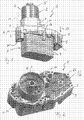
Entsprechend Fig. 1 weist eine Filter-Wärmeübertrager-Kombination 1 für Flüssigkeiten, insbesondere Schmieröl eines Kraftfahrzeug-Verbrennungsmotors, eine Filtereinrichtung 2 und eine Wärmeübertragereinrichtung 3 auf, welche über in Fig. 1 nicht sichtbare Kanäle miteinander verbunden sind. Die Wärmeübertragereinrichtung 3 kann gemäß einer bevorzugten Ausführungsform als Stapelwärmeübertrager ausgebildet sein, welcher aus aufeinander gestapelten und miteinander verbundenen, beispielsweise verlöteten, Metallscheiben 4 gebildet ist. Die Filtereinrichtung 2 besteht im wesentlichen aus einem teilbaren Filtergehäuse 5, das sich aus einem Oberteil 6 und einem damit vorzugsweise verschraubten Unterteil 7 sowie einem nicht sichtbaren, innen liegenden und austauschbaren Filterelement zusammensetzt. Zum Austausch des Filterelementes wird das Oberteil 6 vom Unterteil 7 abgeschraubt und anschließend abgezogen und dadurch das innenliegende Filterelement freigelegt. Günstigerweise ist dabei das Unterteil 7 ein einteiliger, das heißt aus einem Stück hergestellter, Bestandteil einer Oberschale 8, die wie eine Unterschale 9 zwischen der Filtereinrichtung 2 und der Wärmeübertragereinrichtung 3 angeordnet sind.1, a filter-heat exchanger combination 1 for liquids, in particular lubricating oil of a motor vehicle internal combustion engine, a filter device 2 and a
Wie in Fig. 1 bis Fig. 3 gezeigt, ist dabei die Oberschale 8 der Filtereinrichtung 2 und die Unterschale 9 der Wärmeübertragereinrichtung 3 zugeordnet.As shown in FIGS. 1 to 3, the upper shell 8 of the filter device 2 and the lower shell 9 of the
Sowohl die Oberschale 8 als auch die Unterschale 9 sind gemäß der Erfindung aus Kunststoff ausgebildet und zumindest teilweise beziehungsweise bereichsweise von Kanälen durchlaufen. Die Ausbildung der Oberschale 8 an der Unterschale 9 aus Kunststoff bieten den Vorteil einer hohen konstruktiven Freiheit, eine hohe Maßhaltigkeit der beiden Schalen 8, 9 sowie geringe Fertigungskosten. Um die beispielsweise aus der Oberschale 8 und der Unterschale 9 zusammengesetzten Kanäle dicht zu halten, sind beide Schalen 8 und 9 miteinander verschweißt oder verklebt und zwar so, dass die beim normalen Betrieb der Filter-Wärmeübertrager-Kombination 1 auftretenden Drücke problemlos aufgenommen werden können. Von den Kanälen zwischen Ober- und Unterschale 8, 9 sind in Fig. 2 Außenwandkonturen 16 an der Oberfläche der Oberschale 8 erkennbar.Both the upper shell 8 and the lower shell 9 are formed according to the invention of plastic and at least partially or partially traversed by channels. The design of the upper shell 8 on the lower shell 9 made of plastic offer the advantage of a high constructive freedom, a high dimensional accuracy of the two shells 8, 9 and low production costs. In order to keep tight, for example, composed of the upper shell 8 and the lower shell 9 channels, both shells 8 and 9 are welded or glued together in such a way that the pressures occurring during normal operation of the filter heat exchanger combination 1 can be easily absorbed. Of the Channels between upper and lower shell 8, 9 are visible in FIG. 2
Um insbesondere pulsierende Spitzenbelastungen aufnehmen zu können sowie die beiden Schalen 8, 9 zusätzlich zu versteifen, werden diese zusammen mit einer Grundplatte 10 aus Metall, die Bestandteil des Wärmeübertragers 3 ist und direkt auf der Unterschale 9 aufliegt, gegeneinander verspannt. Dies erfolgt über Zuganker 11, welche sich beispielsweise durch fluchtende Öffnungen 15 der Oberschale 8, der Unterschale 9 und der Grundplatte 10 hindurch erstrecken und sich jeweils außerhalb der Öffnungen 15 von Ober- und Unterschale 8, 9 abstützen. Denkbar sind aber auch Zuganker 11, welche entweder einteilig mit der Grundplatte 10 oder der Oberschale 8 ausgebildet sind und sich dementsprechend entweder außerhalb der Oberschale 8 oder außerhalb der Grundplatte 10 abstützen. Darüber hinaus sind aber auch Zuganker 11 vorstellbar, die sich einenends an einer Außenseite der Oberschale 8 und anderenends an einer Außenseite der Grundplatte 10 abstützen und sowohl die Oberschale 8, die Unterschale 9 als auch die Grundplatte 10 außerhalb eines Umfangsrandes in der Art einer U-förmigen Klammer bzw. einer Schraubzwinge umgreifen.In particular, to accommodate pulsating peak loads and stiffen the two shells 8, 9 in addition, these are braced against each other together with a
Die Grundplatte 10 des Wärmeübertragers 3 verhindert im Betrieb der Filter-Wärmeübertrager-Kombination 1 ein Ausweichen beziehungsweise Aufbauchen der Unterschale 9 und gewährleistet dadurch die Dichtheit der zwischen den beiden Schalen 8 und 9 verlaufenden Kanäle bei besonders hohen Drücken und Temperaturen. Gleichzeitig dient die Grundplatte 10 als Verankerung der Zuganker 11, welche die Oberschale 8 gegen die Unterschale 9 vorspannen, wobei der Wärmeübertrager 3 über diese Grundplatte 10 mit Ober- und Unterschale 8, 9 verbunden ist. Dabei kann vorgesehen sein, dass die Zuganker 11 zur Befestigung Verschraubungsmittel enthalten oder mit solchen verbunden sind. Umfasst sein sollen von der Erfindung daher sowohl mehrteilige Verschraubungsmittel, wie beispielsweise Schrauben mit zugehörigen Muttern, als auch einteilige Verschraubungsmittel, welche beispielsweise in ein in die Grundplatte 10 eingebrachtes Innengewinde eingreifen. Zur besseren Lasteinleitung der Vorspannkräfte der Zuganker 11 in die Oberschale 8 können die Verschraubungsmittel beispielsweise als Schrauben mit einem Bundkopf beziehungsweise als Schrauben mit zugehörigen Bundhülsen ausgebildet sein, bei welchen eine auf einer dem Filtergehäuse 5 zugewandten Oberfläche der Oberschale 8 anliegende Auflagefläche als Bund ausgebildet ist. Im Fall der Ausbildung als Bundhülsen kann vorgesehen sein, dass diese auf der der Unterschale 9 abgewandten Seite der Oberschale 8 eingesteckt werden, wogegen ein Befestigungsmittel 12 in Form einer Schraube von der der Oberschale 8 abgewandten Seite der Unterschale 9 in die fluchtenden Öffnungen 15 der Grundplatte 10 eingesteckt und mit der Bundhülse verschraubt wird. Beim Anziehen der Zuganker 11 ist darauf zu achten, dass eine Vorspannkraft derselben unterhalb einer Kriechspannung des für die Oberschale 8 und/oder die Unterschale 9 verwandten Kunststoffes liegt. Dies ist insbesondere wichtig im Hinblick auf die Dichtheit der zwischen der Oberschale 8 und der Unterschale 9 verlaufenden Kanäle. Die Zuganker 11 wirken grundsätzlich wie "Nieten" mit jeweils außen an den Oberflächen der miteinander vernieteten Teile anliegenden Köpfen.The
Zusätzlich zu den bereits beschriebenen Öffnungen 15 weisen die Oberschale 8 und die Unterschale 9 gemäß den Fig. 1 bis 3 weitere fluchtende Öffnungen 15a auf, die zur Aufnahme von nicht abgebildeten Befestigungsmitteln, beispielsweise Schrauben, ausgebildet sind, mit welchen die Filter-Wärmeübertrager-Kombinaton 1 an einer ebenfalls nicht dargestellten Brennkraftmaschine festlegbar ist. Dabei kann vorgesehen sein, dass die Brennkraftmaschine, beispielsweise ein Motorblock, eine zur Wärmeübertragereinrichtung 3 korrespondierende Öffnung aufweist, so dass bei an der Brennkraftmaschine montierter Filter-Wärmeübertrager-Kombination 1 die Wärmeübertragereinrichtung 3 in diese Öffnung hineinragt und damit platzsparend an der Brennkraftmaschine angeordnet werden kann. Für diesen Fall werden die Befestigungsmittel 12 durch die Öffnungen 15a in Pfeilrichtung 13 geführt und mit einem an der Brennkraftmaschine angebrachten Innengewinde in Eingriff gebracht. An der Ober- oder gegebenenfalls auch an der Unterschale 8; 9 liegen die Befestigungsmittel 12 jeweils zugankerartig von außen an.In addition to the
Die Ausbildung sowohl der Oberschale 8 als auch der Unterschale 9 aus Kunststoff eröffnet darüber hinaus die Möglichkeit, an diese Anbau- oder Funktionsteile 14 anzuspritzen. Derartige Anbau- beziehungsweise Funktionsteile 14 können beispielsweise Halter- oder Kupplungselemente sein, welche beispielsweise eine Verbindung mit weiteren nicht dargestellten Teilen innerhalb eines Motorraums erlauben.The formation of both the upper shell 8 and the lower shell 9 made of plastic also opens up the possibility to spray on these attachment or
Alle in der Beschreibung und in den nachfolgenden Ansprüchen dargestellten Merkmale können sowohl einzeln als auch in beliebiger Form miteinander kombiniert erfindungswesentlich sein.All features described in the description and in the following claims can be essential to the invention, both individually and in any desired form.
Claims (9)
gekennzeichnet durch die Merkmale,
characterized by the features
dadurch gekennzeichnet,
dass die Oberschale (8), die Unterschale (9) und die Grundplatte (10) fluchtende Öffnungen (15) aufweisen, in die Zuganker (11) eingebracht sind, die sich jeweils außerhalb der Öffnungen von Ober- und Unterschale (8, 9) abstützen.Filter-heat exchanger combination according to claim 1,
characterized,
in that the upper shell (8), the lower shell (9) and the base plate (10) have aligned openings (15) into which tie rods (11) are inserted, which are each outside the openings of the upper and lower shell (8, 9). support.
dadurch gekennzeichnet,
dass die Zuganker (11) zur Befestigung Verschraubungsmittel enthalten oder mit solchen verbunden sind.Filter-heat exchanger combination according to claim 1 or 2,
characterized,
in that the tie rods (11) for fastening contain or are connected to screwing means.
dadurch gekennzeichnet,
dass die Oberschale (8) und die Unterschale (9) weitere fluchtende Öffnungen (15a) aufweisen, die zur Aufnahme von Befestigungsmitteln (12) ausgebildet sind, mit welchen die Filter-Wärmeübertrager-Kombination (1) an einer Brennkraftmaschine festlegbar ist.Filter-heat exchanger combination according to one of claims 1 to 3,
characterized,
that the upper shell (8) and the lower shell (9) further aligned apertures (15a) which are formed for receiving fastening means (12) with which the filter-heat exchanger combination (1) can be fixed to an internal combustion engine.
dadurch gekennzeichnet,
dass die Oberschale (8) und/oder die Unterschale (9) im Spritzgussverfahren hergestellt sind.Filter-heat exchanger combination according to one of claims 1 to 4,
characterized,
that the upper shell (8) and / or the lower shell (9) are produced by injection molding.
dadurch gekennzeichnet,
dass an die Oberschale (8) und/oder die Unterschale (9) Anbauteile oder Funktionsteile (14) angespritzt sind.Filter-heat exchanger combination according to one of the preceding claims,
characterized,
in that attachment parts or functional parts (14) are injection-molded onto the upper shell (8) and / or the lower shell (9).
dadurch gekennzeichnet,
dass die Filter-Wärmeübertrager-Kombination (1) von einem teilbaren Filtergehäuse (5) mit einem Oberteil (6) und einem damit verschraubten Unterteil (7) sowie einem austauschbaren Filterelement das Unterteil (7) als einteiligem Bestandteil der Oberschale (8) aufweist.Filter-heat exchanger combination according to claim 6,
characterized,
that the filter-heat exchanger combination (1) comprises of a divisible filter housing (5) having an upper part (6) and a screwed to the lower part (7) and a replaceable filter element, the lower part (7) as a one-piece part of the upper shell (8).
dadurch gekennzeichnet,
dass der Wärmeübertrager (3) ein Stapelwärmeübertrager ist, der aus aufeinander gestapelten Metallscheiben (4) gebildet ist.Filter-heat exchanger combination according to one of the preceding claims,
characterized,
that the heat exchanger (3) is a stack of heat exchangers, consisting of stacked metal discs (4) is formed.
dadurch gekennzeichnet,
dass die Oberschale (8) und die Unterschale (9) unter Ausbildung und/oder Aufrechterhaltung dichter Kanäle miteinander verschweißt oder verklebt sind.Filter-heat exchanger combination according to one of the preceding claims,
characterized,
that the upper shell (8) and the lower shell (9) are welded or glued together to form and / or maintain tight channels.
Applications Claiming Priority (1)
| Application Number | Priority Date | Filing Date | Title |
|---|---|---|---|
| DE200510052163 DE102005052163A1 (en) | 2005-11-02 | 2005-11-02 | Filter and heat exchanger combination, has upper housing and lower housing made of plastic, where base plate made of metal is provided between lower housing and heat exchanger equipment |
Publications (2)
| Publication Number | Publication Date |
|---|---|
| EP1782876A1 true EP1782876A1 (en) | 2007-05-09 |
| EP1782876B1 EP1782876B1 (en) | 2008-01-02 |
Family
ID=37651070
Family Applications (1)
| Application Number | Title | Priority Date | Filing Date |
|---|---|---|---|
| EP20060119977 Expired - Fee Related EP1782876B1 (en) | 2005-11-02 | 2006-09-01 | Combination of filter and heat-exchanger for liquids, especially for the lubricant of an internal combustion engine of a vehicle |
Country Status (2)
| Country | Link |
|---|---|
| EP (1) | EP1782876B1 (en) |
| DE (2) | DE102005052163A1 (en) |
Cited By (3)
| Publication number | Priority date | Publication date | Assignee | Title |
|---|---|---|---|---|
| WO2017076766A1 (en) * | 2015-11-03 | 2017-05-11 | Mahle International Gmbh | Heat exchanger module |
| CN110821597A (en) * | 2018-08-13 | 2020-02-21 | 曼·胡默尔有限公司 | Oil filter module with heat exchanger |
| CN111841132A (en) * | 2020-07-04 | 2020-10-30 | 怀宁县群力汽车配件有限公司 | Filter shell convenient to dismouting |
Families Citing this family (1)
| Publication number | Priority date | Publication date | Assignee | Title |
|---|---|---|---|---|
| DE102008031684B4 (en) * | 2008-07-04 | 2020-02-06 | Mahle International Gmbh | cooling device |
Citations (6)
| Publication number | Priority date | Publication date | Assignee | Title |
|---|---|---|---|---|
| GB2163967A (en) * | 1984-08-07 | 1986-03-12 | Nippon Denso Co | Oil filter and cooler |
| EP0551545A1 (en) * | 1990-07-30 | 1993-07-21 | Calsonic Corporation | Housingless oil cooler |
| US5575329A (en) * | 1994-01-14 | 1996-11-19 | Long Manufacturing Ltd. | Passive by-pass for heat exchangers |
| DE19701066A1 (en) * | 1997-01-15 | 1998-07-16 | Mann & Hummel Filter | Device for filtering oil |
| EP1001144A1 (en) * | 1998-11-13 | 2000-05-17 | Denso Corporation | Oil cooler mounting structure |
| EP1403475A1 (en) * | 2002-09-26 | 2004-03-31 | Mann+Hummel Gmbh | Combined fluid filter and heat exchanger device |
Family Cites Families (5)
| Publication number | Priority date | Publication date | Assignee | Title |
|---|---|---|---|---|
| DE19544088A1 (en) * | 1995-11-27 | 1997-05-28 | Knecht Filterwerke Gmbh | Liquid filter with a stacked disc heat exchanger |
| FR2757261B1 (en) * | 1996-12-18 | 1999-02-12 | Valeo Thermique Moteur Sa | BLADE HEAT EXCHANGER WITH INTEGRATED FILTER FOR OIL COOLING |
| DE10012461A1 (en) * | 2000-03-15 | 2001-09-20 | Mahle Filtersysteme Gmbh | Oil filter for cleaning lubricating oil has annular filter insert separating clean side from input side |
| DE10351112A1 (en) * | 2003-11-03 | 2005-05-25 | Mahle Filtersysteme Gmbh | Heat exchanger device used in a motor vehicle as an oil cooler or as a composite part with a filter head for an oil filter comprises a functional part mounted in a receiving device having connecting channels for inlet and outlet openings |
| DE102004040892A1 (en) * | 2004-08-24 | 2006-03-02 | Bayerische Motoren Werke Ag | Lubricant filter for an internal combustion engine |
-
2005
- 2005-11-02 DE DE200510052163 patent/DE102005052163A1/en not_active Withdrawn
-
2006
- 2006-09-01 EP EP20060119977 patent/EP1782876B1/en not_active Expired - Fee Related
- 2006-09-01 DE DE200650000263 patent/DE502006000263D1/en active Active
Patent Citations (6)
| Publication number | Priority date | Publication date | Assignee | Title |
|---|---|---|---|---|
| GB2163967A (en) * | 1984-08-07 | 1986-03-12 | Nippon Denso Co | Oil filter and cooler |
| EP0551545A1 (en) * | 1990-07-30 | 1993-07-21 | Calsonic Corporation | Housingless oil cooler |
| US5575329A (en) * | 1994-01-14 | 1996-11-19 | Long Manufacturing Ltd. | Passive by-pass for heat exchangers |
| DE19701066A1 (en) * | 1997-01-15 | 1998-07-16 | Mann & Hummel Filter | Device for filtering oil |
| EP1001144A1 (en) * | 1998-11-13 | 2000-05-17 | Denso Corporation | Oil cooler mounting structure |
| EP1403475A1 (en) * | 2002-09-26 | 2004-03-31 | Mann+Hummel Gmbh | Combined fluid filter and heat exchanger device |
Cited By (7)
| Publication number | Priority date | Publication date | Assignee | Title |
|---|---|---|---|---|
| WO2017076766A1 (en) * | 2015-11-03 | 2017-05-11 | Mahle International Gmbh | Heat exchanger module |
| CN108351186A (en) * | 2015-11-03 | 2018-07-31 | 马勒国际有限公司 | Heat exchanger module |
| JP2018534482A (en) * | 2015-11-03 | 2018-11-22 | マーレ インターナショナル ゲゼルシャフト ミット ベシュレンクテル ハフツングMAHLE International GmbH | Heat exchanger module |
| US10473402B2 (en) | 2015-11-03 | 2019-11-12 | Mahle International Gmbh | Heat exchanger module |
| CN110821597A (en) * | 2018-08-13 | 2020-02-21 | 曼·胡默尔有限公司 | Oil filter module with heat exchanger |
| CN110821597B (en) * | 2018-08-13 | 2023-08-04 | 曼·胡默尔有限公司 | Oil filter module with heat exchanger |
| CN111841132A (en) * | 2020-07-04 | 2020-10-30 | 怀宁县群力汽车配件有限公司 | Filter shell convenient to dismouting |
Also Published As
| Publication number | Publication date |
|---|---|
| DE502006000263D1 (en) | 2008-02-14 |
| DE102005052163A1 (en) | 2007-05-03 |
| EP1782876B1 (en) | 2008-01-02 |
Similar Documents
| Publication | Publication Date | Title |
|---|---|---|
| EP3163242B1 (en) | Indirect charge-air cooler | |
| DE102005007591A1 (en) | heat exchangers | |
| EP0928405A2 (en) | Plate-type heat exchanger, especially oil/coolant cooler in vehicles | |
| EP2929210B1 (en) | Damper for a vehicle having a flange for connecting an external module tube | |
| EP2730456B1 (en) | Drive for a seat adjusting device for motor vehicles | |
| EP2177725B2 (en) | Filter device | |
| DE19511479C2 (en) | Connecting device | |
| EP2154465B1 (en) | Plate heat exchanger | |
| EP1782876B1 (en) | Combination of filter and heat-exchanger for liquids, especially for the lubricant of an internal combustion engine of a vehicle | |
| DE102017109708A1 (en) | Cooling arrangement, fluid collector for a cooling arrangement and method for producing a fluid collector | |
| EP0758969B1 (en) | Rack and pinion power steering gear, in particular for motor vehicles | |
| DE102005029842A1 (en) | Fuel storage of a fuel injection system of a motor vehicle | |
| EP3037150B1 (en) | Filter device | |
| EP2308710B1 (en) | Commercial vehicle tank | |
| DE10301018B4 (en) | Arrangement for connecting a tubular first component to a second component and method for producing such an arrangement | |
| EP1712419A1 (en) | Roof rack assembly and a method for manufacturing a roof rack assembly | |
| EP2331805B1 (en) | Filter device for internal combustion engines | |
| EP3179060A1 (en) | Cylinder head cover | |
| DE102005002005B4 (en) | Cooling device, in particular for an electrical transformer | |
| DE102008049990B4 (en) | Storage device and method for manufacturing a storage device | |
| EP1740801B1 (en) | Oil or liquid container which can be directly fixed to a fixing surface | |
| EP3088834A1 (en) | Heat exchanger | |
| EP1936141A2 (en) | Valve for regulating a flowing medium | |
| EP2043754A1 (en) | Liquid heat exchanger unit | |
| DE19642672A1 (en) | Tube board |
Legal Events
| Date | Code | Title | Description |
|---|---|---|---|
| PUAI | Public reference made under article 153(3) epc to a published international application that has entered the european phase |
Free format text: ORIGINAL CODE: 0009012 |
|
| AK | Designated contracting states |
Kind code of ref document: A1 Designated state(s): AT BE BG CH CY CZ DE DK EE ES FI FR GB GR HU IE IS IT LI LT LU LV MC NL PL PT RO SE SI SK TR |
|
| AX | Request for extension of the european patent |
Extension state: AL BA HR MK YU |
|
| 17P | Request for examination filed |
Effective date: 20070717 |
|
| GRAP | Despatch of communication of intention to grant a patent |
Free format text: ORIGINAL CODE: EPIDOSNIGR1 |
|
| GRAS | Grant fee paid |
Free format text: ORIGINAL CODE: EPIDOSNIGR3 |
|
| GRAA | (expected) grant |
Free format text: ORIGINAL CODE: 0009210 |
|
| AK | Designated contracting states |
Kind code of ref document: B1 Designated state(s): DE FR GB |
|
| REG | Reference to a national code |
Ref country code: GB Ref legal event code: FG4D Free format text: NOT ENGLISH |
|
| AKX | Designation fees paid |
Designated state(s): DE FR GB |
|
| REF | Corresponds to: |
Ref document number: 502006000263 Country of ref document: DE Date of ref document: 20080214 Kind code of ref document: P |
|
| GBT | Gb: translation of ep patent filed (gb section 77(6)(a)/1977) |
Effective date: 20080213 |
|
| ET | Fr: translation filed | ||
| PLBE | No opposition filed within time limit |
Free format text: ORIGINAL CODE: 0009261 |
|
| STAA | Information on the status of an ep patent application or granted ep patent |
Free format text: STATUS: NO OPPOSITION FILED WITHIN TIME LIMIT |
|
| 26N | No opposition filed |
Effective date: 20081003 |
|
| REG | Reference to a national code |
Ref country code: FR Ref legal event code: PLFP Year of fee payment: 10 |
|
| REG | Reference to a national code |
Ref country code: FR Ref legal event code: PLFP Year of fee payment: 11 |
|
| REG | Reference to a national code |
Ref country code: FR Ref legal event code: PLFP Year of fee payment: 12 |
|
| REG | Reference to a national code |
Ref country code: FR Ref legal event code: PLFP Year of fee payment: 13 |
|
| PGFP | Annual fee paid to national office [announced via postgrant information from national office to epo] |
Ref country code: FR Payment date: 20180928 Year of fee payment: 13 |
|
| PGFP | Annual fee paid to national office [announced via postgrant information from national office to epo] |
Ref country code: GB Payment date: 20180928 Year of fee payment: 13 |
|
| PGFP | Annual fee paid to national office [announced via postgrant information from national office to epo] |
Ref country code: DE Payment date: 20181130 Year of fee payment: 13 |
|
| REG | Reference to a national code |
Ref country code: DE Ref legal event code: R119 Ref document number: 502006000263 Country of ref document: DE |
|
| PG25 | Lapsed in a contracting state [announced via postgrant information from national office to epo] |
Ref country code: DE Free format text: LAPSE BECAUSE OF NON-PAYMENT OF DUE FEES Effective date: 20200401 |
|
| GBPC | Gb: european patent ceased through non-payment of renewal fee |
Effective date: 20190901 |
|
| PG25 | Lapsed in a contracting state [announced via postgrant information from national office to epo] |
Ref country code: FR Free format text: LAPSE BECAUSE OF NON-PAYMENT OF DUE FEES Effective date: 20190930 Ref country code: GB Free format text: LAPSE BECAUSE OF NON-PAYMENT OF DUE FEES Effective date: 20190901 |