EP1782102B1 - A security entrance system - Google Patents
A security entrance system Download PDFInfo
- Publication number
- EP1782102B1 EP1782102B1 EP05774424.5A EP05774424A EP1782102B1 EP 1782102 B1 EP1782102 B1 EP 1782102B1 EP 05774424 A EP05774424 A EP 05774424A EP 1782102 B1 EP1782102 B1 EP 1782102B1
- Authority
- EP
- European Patent Office
- Prior art keywords
- ray
- walk
- gate
- detector
- substances
- Prior art date
- Legal status (The legal status is an assumption and is not a legal conclusion. Google has not performed a legal analysis and makes no representation as to the accuracy of the status listed.)
- Active
Links
Images


Classifications
-
- G—PHYSICS
- G01—MEASURING; TESTING
- G01T—MEASUREMENT OF NUCLEAR OR X-RADIATION
- G01T1/00—Measuring X-radiation, gamma radiation, corpuscular radiation, or cosmic radiation
- G01T1/16—Measuring radiation intensity
- G01T1/161—Applications in the field of nuclear medicine, e.g. in vivo counting
- G01T1/163—Whole body counters
Definitions
- the invention is related to the systems of so-called "security entrance” and, in particular, to the systems for preventing the entry of forbidden articles and/or substances from an unprotected area to a protected one.
- JP-A-2004069576 discloses an X-ray inspection apparatus for obtaining an X-ray image of a single person, comprising an inspection passage and an X-ray photographic apparatus comprising an X-ray source and an X-ray detector.
- DE-A-4335202 discloses an X-ray gate comprising an X-ray source and a vertical array of X-ray receivers.
- a security system for preventing the entry of forbidden articles and/or substances from a surrounding area to a protected one, said system comprised of a partitioning separating a protected area from an unprotected one, at least, one walk-gate made in said partitioning, an information control-and-processing device and a detector of forbidden articles and/or substances, wherein said detector of forbidden articles and/or substances is made an X-ray kind to provide secret examination of every person passing through said walk-gate, wherein an X-ray receiver of said detector made as a vertical linear X-ray receiver is built-in into the walk-gate element opposite to said X-ray radiation source, and wherein said element that is used to build-in said X-ray receiver is a movable door with a drive mechanism of said door made so that it maintains the pre-defined ratio of the door motion speed and of the scanning rate of an X-ray radiation source.
- At least one walk-gate in said partitioning is preferably supplied with at least one door with a respective drive mechanism connected to a drive signal output of an information control-and-processing device.
- a detector of forbidden articles and/or substances is preferably supplied with an X-ray scanning radiation source and an X-ray receiver that is co-linear to said X-ray radiation and is connected to the information inputs of an information control-and-processing device.
- An X-ray radiation source of said detector of forbidden articles and/or substances is made to generate a flat fan-shaped X-ray beam in the walk-gate plane and can be disposed behind the bottom part of one of the side walls of said walk-gate provided with, at least, one X-ray transparent portion or it can be built-in into said bottom part of one of said walk-gate side walls.
- An X-ray receiver of said detector made as a vertical linear X-ray receiver can be disposed behind the walk-gate element opposite to said X-ray radiation source, for example, behind the walk-gate second side wall provided with, at least, one X-ray transparent portion.
- An X-ray receiver of said detector made as a horizontal linear X-ray receiver can be disposed under the walk-gate floor provided with, at least, one X-ray transparent portion or built-in into said walk-gate floor.
- An X-ray receiver of said detector made as a horizontal linear X-ray receiver can be disposed above the walk-gate ceiling provided with, at least, one X-ray transparent portion or built-in into said walk-gate ceiling.
- a walk-gate is additionally supplied with a sensor to define the presence of a person ready to pass through said walk-gate with an output of said sensor being connected to the input for activating an X-ray radiation source.
- a system filed according to any of its implementations is comprised of a partitioning 1 separating a protected area 2 from an unprotected area 3.
- a partitioning 1 is comprised of at least one walk-gate 4 leading from an unprotected area 3 to a protected one.
- a walk-gate 4 is closed with, at least, one door 5 which is preferably made a movable one.
- a system also comprises a detector of forbidden articles and/or substances comprised of an X-ray radiation source 6 supplied with a collimator 7 for generating a flat fan-shaped X-ray beam 8 in the plane of a walk-gate 4 and an X-ray receiver 9 that is co-linear to said X-ray beam 8.
- An X-ray receiver 9 in all implementations of a system filed is made a linear one and presents in itself a linear array of the elements for converting an X-ray radiation through a visible light into the digital electronic signals. Also there is provided an information control-and-processing device 10.
- an X-ray radiation source 6 with a collimator 7 is located in the premises 11 that are disposed under the angle of 90° to a walk-gate 4 and are adjacent to a side-wall 12 wherein an X-ray transparent portion 13 is provided.
- an X-ray transparent portion 15 In an opposite wall 14 of a walk-gate 4 there is also provided an X-ray transparent portion 15 with a vertical linear X-ray receiver 9 disposed further behind.
- An X-ray receiver is made a movable one so that it can be moved parallel to itself along a portion 15 in close synchronism with the scanning motion of an X-ray beam 8.
- An information control-and-processing device 10 is made as a computer-controlled work station equipped with special software to process the image thus received and also to control the synchronous motion of a collimator 7 and of an X-ray receiver 9.
- a walk-gate 4 is closed with a movable door 5.
- a sensor for defining the presence of a person ready to pass through said walk-gate in the implementation example described is made as a video camera 16 though it can be made by any means known to those skilled in the art.
- an X-ray radiation source 6 with a collimator 7 is disposed in the premises 17 made behind a walk-gate 4.
- an X-ray transparent portion 19 In the end wall 18 of a walk-gate 4 there is provided an X-ray transparent portion 19.
- the opposite end wall of a walk-gate 4 is closed with a movable door 5 with a vertical linear X-ray receiver 9 secured therein.
- An information control-and-processing device 10 is made as a computer-controlled work station equipped with special software to process the image thus received and also to control the synchronous motion of a collimator 7 and of an X-ray receiver 9.
- a drive mechanism (not shown in the drawings) of a door 5 is made so that it maintains the pre-defined ratio of the door motion speed and of the scanning rate of an X-ray radiation source and is coupled to an output of an information control-and processing device 10.
- an X-ray radiation source 6 with a collimator 7 are disposed in the premises 20 parallel to a walk-gate 4.
- an X-ray transparent portion 22 In their adjacent wall 21 there is provided an X-ray transparent portion 22.
- An end wall of a walk-gate 4 is closed with a movable door 5 with a vertical linear X-ray receiver 9 secured there on.
- the system is additionally supplied with a horizontal X-ray receiver 23 disposed on the ceiling of a walk-gate 4 across the latter, while the scanning flat fan-shaped X-ray beam 8 is generated in such a way that to enclose both a vertical detector 9 and a horizontal X-ray receiver 23.
- An information control-and-processing device 10 is made as a computer-controlled work station equipped with special software to process the image thus received and also to control the synchronous motion of a collimator 7 and of an X-ray receiver 9.
- a drive mechanism (not shown in the drawings) of a door 5 is made so that it maintains the pre-defined ratio of the door motion speed and of the scanning rate of an X-ray radiation source and is coupled to an output of an information control-and processing device 10.
- An X-ray radiation source 6 can be secured in the wall of a walk-gate 4. However, the most preferable one is the position illustrated in Fig. 4 with a an X-ray radiation source 6 and a collimator 7 disposed in the premises 24 adjacent to a walk-gate 4, while an. X-ray transparent portion 26 is provided in their adjacent wall 25.
- a vertical linear X-ray receiver 9 is secured on the opposite wall 27 of a walk-gate 4.
- a flat fan-shaped X-ray beam is generated in such a way that it could hit upon a vertical X-ray receiver 9 with high precision. Scanning is provided by means of the walk-gate floor 28 that is moving with a constant speed i.e. according to the principle of "a moving pavement” or an escalator.
- An information control-and-processing device 10 is made as a computer-controlled work station equipped with special software to process the image thus received and also to control the motion of the floor 28.
- An X-ray radiation source emits a flow of X-ray beams to be shaped by a collimator 7 into one flat vertical X-ray beam 8.
- a collimator 7 and an X-ray receiver 9 are pre-set in such a manner that a vertical X-ray beam 8 hits upon an X-ray receiver 9 with high precision.
- a highly precise synchronous movement can be provided, for example, by means of positioning a collimator 7 and an X-ray receiver 9 (or a door 5) on the respective horizontal guides and their movement there along said guides by means of the step motors (not shown in the drawings).
- a synchronous motion of a collimator 7 and that of an X-ray receiver 9 is achieved due to highly precise ratio of their speeds. Since the rotational speed of the step motors is in the end defined by the switching rate of its windings to provide the synchronous motion it is necessary to synthesize the two frequencies having the precisely defined ratio. The possibility is also provided to vary said ratio in very small increments.
- a sensor 24 for defining the presence of a person ready to pass through a walk-gate 4 supplies the signal of the presence of said person and in this way activates an X-ray radiation source 6.
- a sensor 24 can be made, for example, as a video camera as it is shown in Fig.1 .
- An X-ray beam 8 is passed through the X-ray transparent portions 13, 19, 22 or 26 of the walls 12, 18, 21, 25 ( Fig. 1 , 2 , 3 , 4 respectively) or without the latter and further through a human body 29 and then through an X-ray transparent portion 15 of a wall 14 ( Fig. 1 ) or directly ( Fig. 2 , 3 or 4 ) and at each given scanning interval it hits upon an X-ray receiver 9 with the resulting read-out of the electronic digital signals.
- the output electronic digital signals are supplied to the information control-and-processing device 10 that generates the image of a person 29 being examined. Due to the projection characteristics of the image thus received just one passing of a person being examined through a walk-gate provides the required information about the presence of forbidden articles and/or substances both on the surface and in the internal cavities of a human body.
- the latter can be additionally supplied with two more doors (not shown in the drawings) disposed after said movable door 5 and controlled by an information control-and-processing device 10.
- These doors can be operated, for example, as it is described in [ US 2003020607 , Int.Cl. G08B21/00, Published 30.01.2003].
- the maximum dose received by a person per one scanning is of 0,1 ⁇ Zv which is in conformity with international radiation safety standards without any limitations as to the number of examinations including pregnant women and children.
- Such a low dose is achieved due to optimization of anode voltage and current of an X-ray radiation source 7 and the value of its output filter, the width of a collimator slot, the dimensions of X-ray sensitive components of an X-ray receiver 9 and the scanning time.
Description
- The invention is related to the systems of so-called "security entrance" and, in particular, to the systems for preventing the entry of forbidden articles and/or substances from an unprotected area to a protected one.
- Known are a number of "security entrance" systems based on various concepts such as monitoring the entrance by means of radar devices [
DE 19817396 , Int.Cl.: G08B13./183, G01S13/04, Published 21.10.1999] or the use of the pass cards equipped with IR-radiators [FR283108, Int.Cl.: G08B13/19, Published 25.04.2003]. Such systems make it possible to restrict the access to the protected area of the strangers but they are not suitable for providing a security entrance when most of those entering are casual visitors to the place like in the airports, railway terminals, bus stations as well as in the banks, large trading centers etc. These places nowadays present the greatest danger from the viewpoint of their susceptibility to various unlawful acts contemplating the use of both metal and plastic weapons including plastic explosives. - Known are the systems of security entrance employing a number of various methods that make it possible to reveal the attempts of entry of the weapons, explosives or drugs to the protected area. In [International Application
WO9921148 - Not less complicated is a system of security entrance [
US6472984 , Int.Cl.:G08B21/00, Published 29.10.2002] wherein a partitioning separating a protected area from an unprotected one is equipped with two or three walk-gates each provided with an appropriate door. A metal detector is used as a detector of forbidden articles. There is also available a weight control device of an examination zone and an information control-and-processing device. - Besides being very complicated and expensive such system do not provide the required secrecy of examination.
-
JP-A-2004069576 -
DE-A-4335202 discloses an X-ray gate comprising an X-ray source and a vertical array of X-ray receivers. - It is the aim of the present invention to design a comprehensive security system providing secret examination of every person passing through a walk-gate.
- This aim is achieved by means of a security system for preventing the entry of forbidden articles and/or substances from a surrounding area to a protected one, said system comprised of a partitioning separating a protected area from an unprotected one, at least, one walk-gate made in said partitioning, an information control-and-processing device and a detector of forbidden articles and/or substances, wherein said detector of forbidden articles and/or substances is made an X-ray kind to provide secret examination of every person passing through said walk-gate, wherein an X-ray receiver of said detector made as a vertical linear X-ray receiver is built-in into the walk-gate element opposite to said X-ray radiation source, and wherein said element that is used to build-in said X-ray receiver is a movable door with a drive mechanism of said door made so that it maintains the pre-defined ratio of the door motion speed and of the scanning rate of an X-ray radiation source.
- At least one walk-gate in said partitioning is preferably supplied with at least one door with a respective drive mechanism connected to a drive signal output of an information control-and-processing device.
- A detector of forbidden articles and/or substances is preferably supplied with an X-ray scanning radiation source and an X-ray receiver that is co-linear to said X-ray radiation and is connected to the information inputs of an information control-and-processing device.
- An X-ray radiation source of said detector of forbidden articles and/or substances is made to generate a flat fan-shaped X-ray beam in the walk-gate plane and can be disposed behind the bottom part of one of the side walls of said walk-gate provided with, at least, one X-ray transparent portion or it can be built-in into said bottom part of one of said walk-gate side walls.
- An X-ray receiver of said detector made as a vertical linear X-ray receiver can be disposed behind the walk-gate element opposite to said X-ray radiation source, for example, behind the walk-gate second side wall provided with, at least, one X-ray transparent portion.
- An X-ray receiver of said detector made as a horizontal linear X-ray receiver can be disposed under the walk-gate floor provided with, at least, one X-ray transparent portion or built-in into said walk-gate floor.
- An X-ray receiver of said detector made as a horizontal linear X-ray receiver can be disposed above the walk-gate ceiling provided with, at least, one X-ray transparent portion or built-in into said walk-gate ceiling.
- Preferably a walk-gate is additionally supplied with a sensor to define the presence of a person ready to pass through said walk-gate with an output of said sensor being connected to the input for activating an X-ray radiation source.
- The implementation examples of the present invention are illustrated in the following drawings.
-
-
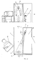
Fig. 1 is a schematic diagram of an implementation example of a system filed wherein both an X-ray radiation source and an X-ray receiver are disposed behind the walk-gate walls: (a) - a front view, b - a plane view. -
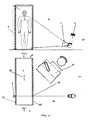
Fig. 2 is a schematic diagram of an implementation example of a system filed wherein an X-ray radiation source is disposed behind a walk-gate wall, and an X-ray receiver is disposed in a movable door: (a) - a front view, b - a plane view. -
Fig. 3 is a schematic diagram of an implementation example of a system filed wherein an X-ray radiation source is disposed behind a walk-gate wall, and an X-ray receiver is disposed in a movable door: (a) - a front view, b - a plane view. -
Fig. 4 is a schematic diagram of an implementation example of a system filed wherein an X-ray radiation source is disposed behind a walk-gate wall and, an X-ray receiver is disposed in said walk-gate wall: (a) - a front view, b - plane view. - A system filed according to any of its implementations is comprised of a partitioning 1 separating a protected
area 2 from anunprotected area 3. Apartitioning 1 is comprised of at least onewalk-gate 4 leading from anunprotected area 3 to a protected one. Awalk-gate 4 is closed with, at least, onedoor 5 which is preferably made a movable one. A system also comprises a detector of forbidden articles and/or substances comprised of anX-ray radiation source 6 supplied with acollimator 7 for generating a flat fan-shaped X-ray beam 8 in the plane of awalk-gate 4 and anX-ray receiver 9 that is co-linear to saidX-ray beam 8. AnX-ray receiver 9 in all implementations of a system filed is made a linear one and presents in itself a linear array of the elements for converting an X-ray radiation through a visible light into the digital electronic signals. Also there is provided an information control-and-processing device 10. - In the implementation example presented in
Fig.1 anX-ray radiation source 6 with acollimator 7 is located in thepremises 11 that are disposed under the angle of 90° to awalk-gate 4 and are adjacent to a side-wall 12 wherein an X-raytransparent portion 13 is provided. In anopposite wall 14 of awalk-gate 4 there is also provided an X-raytransparent portion 15 with a verticallinear X-ray receiver 9 disposed further behind. An X-ray receiver is made a movable one so that it can be moved parallel to itself along aportion 15 in close synchronism with the scanning motion of anX-ray beam 8. An information control-and-processing device 10 is made as a computer-controlled work station equipped with special software to process the image thus received and also to control the synchronous motion of acollimator 7 and of anX-ray receiver 9. Awalk-gate 4 is closed with amovable door 5. A sensor for defining the presence of a person ready to pass through said walk-gate in the implementation example described is made as avideo camera 16 though it can be made by any means known to those skilled in the art. - In the implementation example illustrated in
Fig. 2 anX-ray radiation source 6 with acollimator 7 is disposed in thepremises 17 made behind awalk-gate 4. In theend wall 18 of awalk-gate 4 there is provided an X-raytransparent portion 19. The opposite end wall of awalk-gate 4 is closed with amovable door 5 with a verticallinear X-ray receiver 9 secured therein. An information control-and-processing device 10 is made as a computer-controlled work station equipped with special software to process the image thus received and also to control the synchronous motion of acollimator 7 and of anX-ray receiver 9. A drive mechanism (not shown in the drawings) of adoor 5 is made so that it maintains the pre-defined ratio of the door motion speed and of the scanning rate of an X-ray radiation source and is coupled to an output of an information control-andprocessing device 10. - In the implementation example illustrated in
Fig.3 anX-ray radiation source 6 with acollimator 7 are disposed in thepremises 20 parallel to awalk-gate 4. In their adjacent wall 21 there is provided an X-raytransparent portion 22. An end wall of awalk-gate 4 is closed with amovable door 5 with a verticallinear X-ray receiver 9 secured there on. The system is additionally supplied with a horizontal X-ray receiver 23 disposed on the ceiling of awalk-gate 4 across the latter, while the scanning flat fan-shaped X-ray beam 8 is generated in such a way that to enclose both avertical detector 9 and a horizontal X-ray receiver 23. An information control-and-processing device 10 is made as a computer-controlled work station equipped with special software to process the image thus received and also to control the synchronous motion of acollimator 7 and of anX-ray receiver 9. A drive mechanism (not shown in the drawings) of adoor 5 is made so that it maintains the pre-defined ratio of the door motion speed and of the scanning rate of an X-ray radiation source and is coupled to an output of an information control-andprocessing device 10. - An
X-ray radiation source 6 can be secured in the wall of awalk-gate 4. However, the most preferable one is the position illustrated inFig. 4 with a anX-ray radiation source 6 and acollimator 7 disposed in thepremises 24 adjacent to awalk-gate 4, while an. X-raytransparent portion 26 is provided in theiradjacent wall 25. A verticallinear X-ray receiver 9 is secured on theopposite wall 27 of awalk-gate 4. A flat fan-shaped X-ray beam is generated in such a way that it could hit upon avertical X-ray receiver 9 with high precision. Scanning is provided by means of thewalk-gate floor 28 that is moving with a constant speed i.e. according to the principle of "a moving pavement" or an escalator. Such implementation of a system filed is especially suitable for the pedestrian subways in the airports where a wide use is made of such "moving pavements" or escalators. An information control-and-processing device 10 is made as a computer-controlled work station equipped with special software to process the image thus received and also to control the motion of thefloor 28. - The operation of the system filed is performed in the following way.
- An X-ray radiation source emits a flow of X-ray beams to be shaped by a
collimator 7 into one flatvertical X-ray beam 8. - A
collimator 7 and anX-ray receiver 9 are pre-set in such a manner that avertical X-ray beam 8 hits upon anX-ray receiver 9 with high precision. - A highly precise synchronous movement can be provided, for example, by means of positioning a
collimator 7 and an X-ray receiver 9 (or a door 5) on the respective horizontal guides and their movement there along said guides by means of the step motors (not shown in the drawings). - The synchronization design concepts of the motion system are described, for example, in [International Application
WO02/7306 X-ray receiver 9 is moved with a constant speed. Acollimator 7 is moved in synchronism with the motion of an X-ray receiver '9 in such a manner that a slot shadow projection of acollimator 7 from an X-ray beam emitted by anX-ray radiation source 6 is constantly located on anX-ray receiver 9. - As it follows from the similarity considerations to provide the constant projection of a
collimator 7 on an X-ray receiver throughout the scanning range it is sufficient to perform the motion of both components with time according to one and the same law. Such design concept of a motion system makes it possible to provide its technical implementation by relatively simple means i.e. to make the motion a synchronous one acollimator 7 and anX-ray receiver 9 should be moved with constant speeds. - A synchronous motion of a
collimator 7 and that of anX-ray receiver 9 is achieved due to highly precise ratio of their speeds. Since the rotational speed of the step motors is in the end defined by the switching rate of its windings to provide the synchronous motion it is necessary to synthesize the two frequencies having the precisely defined ratio. The possibility is also provided to vary said ratio in very small increments. - A
sensor 24 for defining the presence of a person ready to pass through a walk-gate 4 supplies the signal of the presence of said person and in this way activates anX-ray radiation source 6. Asensor 24 can be made, for example, as a video camera as it is shown inFig.1 . - An
X-ray beam 8 is passed through the X-raytransparent portions walls Fig. 1 ,2 ,3 ,4 respectively) or without the latter and further through ahuman body 29 and then through an X-raytransparent portion 15 of a wall 14 (Fig. 1 ) or directly (Fig. 2 ,3 or4 ) and at each given scanning interval it hits upon anX-ray receiver 9 with the resulting read-out of the electronic digital signals. The output electronic digital signals are supplied to the information control-and-processingdevice 10 that generates the image of aperson 29 being examined. Due to the projection characteristics of the image thus received just one passing of a person being examined through a walk-gate provides the required information about the presence of forbidden articles and/or substances both on the surface and in the internal cavities of a human body. - To improve the safety of a system filed the latter can be additionally supplied with two more doors (not shown in the drawings) disposed after said
movable door 5 and controlled by an information control-and-processingdevice 10. These doors can be operated, for example, as it is described in [US 2003020607 , Int.Cl. G08B21/00, Published 30.01.2003]. After scanning aperson 29 passes through adoor 5 which is closed after him. Then before a person there is opened only one of the other two doors. If the analysis of the scanning image of a person under examination does not reveal any forbidden articles and/or substances, then there is opened one of the doors leading to the protected area. Should said analysis of the scanning image of a person under examination reveal some forbidden articles and/or substances, then there is opened another door leading to the inspection premises. The image analysis is performed by a computer-controlled work station or by more remote control devices. A person being examined is not aware of either the scanning or its results or of where the door he/or she is passing through leads to. - The maximum dose received by a person per one scanning is of 0,1µZv which is in conformity with international radiation safety standards without any limitations as to the number of examinations including pregnant women and children. Such a low dose is achieved due to optimization of anode voltage and current of an
X-ray radiation source 7 and the value of its output filter, the width of a collimator slot, the dimensions of X-ray sensitive components of anX-ray receiver 9 and the scanning time.
Claims (10)
- A security entrance system for preventing the entry of forbidden articles and/or substances from a surrounding area to a protected one comprised of a partitioning (1) separating a protected area (2) from an unprotected one (3), at least, one walk-gate (4) made in said partitioning (1), an information control-and-processing device (10) and a detector of forbidden articles and/or substances, wherein said detector of forbidden articles and/or substances is made an X-ray kind to provide secret examination of every person passing through said walk-gate (4);
wherein an X-ray receiver (9) of said detector is made as a vertical linear X-ray receiver built-in into the walk-gate element opposite to an X-ray radiation source (6); and
wherein said element that said X-ray receiver (9) is built-in is a movable door (5) with a drive mechanism of said door made so that it maintains the pre-defined ratio of the door motion speed and of the scanning rate of an X-ray radiation source (6). - A security entrance system as in claim 1, wherein, at least one walk-gate (4) in said partitioning (1) is supplied with, at least, one door (5) with a respective drive mechanism connected to a signal output of an information control-and-processing device (10).
- A security entrance system as in claim 1, wherein said detector of forbidden articles and/or substances is comprised of an X-ray scanning radiation source (6) and of an X-ray receiver (9) that is co-linear to said X-ray radiation and is connected to the information inputs of an information control-and-processing device (10).
- A security entrance system as in any of the claims from 1 to 3, wherein said X-ray radiation source (6) of said detector of forbidden articles and/or substances is made to generate a flat fan-shaped X-ray beam (8) in the walk-gate plane and can be disposed behind the bottom part of one of the walk-gate side walls provided with, at least, one X-ray transparent portion (22).
- A security entrance system as in any of the claims from 1 to 3, wherein said X-ray radiation source (6) of said detector of forbidden articles and/or substances is made to generate a flat fan-shaped X-ray beam (8) in the walk-gate plane and is built-in into the bottom part of one of the walk-gate side walls.
- A security entrance system as in any of the preceding claims, wherein said detector of forbidden articles and/or substances further comprises a horizontal linear X-ray receiver (23) disposed under the walk-gate floor provided with, at least, one X-ray transparent portion or built-in into said walk-gate floor.
- A security entrance system as in any of the preceding claims, wherein said detector of forbidden articles and/or substances further comprises a horizontal linear X-ray receiver (23) built-in into said walk-gate floor.
- A security entrance system as in any of the preceding claims, wherein said detector of forbidden articles and/or substances further comprises a horizontal linear X-ray receiver (23) disposed above the walk-gate ceiling provided with, at least, one X-ray transparent portion.
- A security entrance system as in any of the preceding claims, wherein said detector of forbidden articles and/or substances further comprises a horizontal linear X-ray receiver (23) built-in into said walk-gate ceiling.
- A security entrance system as in any of the preceding claims, wherein said walk-gate (4) is additionally supplied with a sensor (24) to define the presence of a person ready to pass through said walk-gate (4) with an output of said sensor (24) being connected to the input for activating an X-ray radiation source (6).
Applications Claiming Priority (2)
| Application Number | Priority Date | Filing Date | Title |
|---|---|---|---|
| BY20040750 | 2004-08-09 | ||
| PCT/BY2005/000007 WO2006015471A1 (en) | 2004-08-09 | 2005-08-05 | A security entrance system |
Publications (2)
| Publication Number | Publication Date |
|---|---|
| EP1782102A1 EP1782102A1 (en) | 2007-05-09 |
| EP1782102B1 true EP1782102B1 (en) | 2013-10-09 |
Family
ID=34978717
Family Applications (1)
| Application Number | Title | Priority Date | Filing Date |
|---|---|---|---|
| EP05774424.5A Active EP1782102B1 (en) | 2004-08-09 | 2005-08-05 | A security entrance system |
Country Status (6)
| Country | Link |
|---|---|
| US (1) | US7397892B2 (en) |
| EP (1) | EP1782102B1 (en) |
| CN (1) | CN101036070B (en) |
| EA (1) | EA009224B1 (en) |
| HK (1) | HK1107406A1 (en) |
| WO (1) | WO2006015471A1 (en) |
Families Citing this family (14)
| Publication number | Priority date | Publication date | Assignee | Title |
|---|---|---|---|---|
| DE202006015603U1 (en) * | 2006-10-11 | 2008-02-21 | Fraport Ag Frankfurt Airport Services Worldwide | Handling and security control system for air cargo loading units |
| US8275093B2 (en) * | 2009-07-30 | 2012-09-25 | American Science And Engineering, Inc. | Walk-through shoe inspection system |
| EA024045B1 (en) * | 2010-05-05 | 2016-08-31 | Научно-Производственное Частное Унитарное Предприятие Адани | Moving heavy vehicle inspection system |
| CN101950036A (en) * | 2010-08-06 | 2011-01-19 | 深圳市鑫源通电子有限公司 | Hidden security inspection door |
| DE102010044802A1 (en) * | 2010-09-09 | 2012-03-15 | Smiths Helmann Gmbh | Device for the detection of suspicious objects |
| US8766764B2 (en) * | 2010-09-23 | 2014-07-01 | Rapiscan Systems, Inc. | Automated personnel screening system and method |
| US9513385B2 (en) | 2011-11-18 | 2016-12-06 | Visuum, Llc | Multi-linear x-ray scanning systems and methods for x-ray scanning |
| US9121809B2 (en) * | 2011-11-18 | 2015-09-01 | Visuum, Llc | Multi-linear X-ray scanning systems and methods for X-ray scanning |
| US8989348B2 (en) * | 2011-11-18 | 2015-03-24 | Visuum, Llc | Multi-linear X-ray scanning systems and methods for X-ray scanning |
| US8819855B2 (en) | 2012-09-10 | 2014-08-26 | Mdi Security, Llc | System and method for deploying handheld devices to secure an area |
| US9000380B2 (en) * | 2013-05-16 | 2015-04-07 | Elwha Llc | Security scanning device |
| DE102014217391A1 (en) * | 2014-09-01 | 2016-03-03 | Smiths Heimann Gmbh | Detector line with areas of different resolution |
| CN104880735A (en) * | 2015-06-10 | 2015-09-02 | 深圳黎明镒清图像技术有限公司 | Integrated X-ray safety check device and safety check method |
| RU2711177C1 (en) * | 2019-04-18 | 2020-01-15 | Закрытое акционерное общество "Сфинкс" | Inspection system with wireless data transmission |
Family Cites Families (22)
| Publication number | Priority date | Publication date | Assignee | Title |
|---|---|---|---|---|
| US4586441A (en) * | 1982-06-08 | 1986-05-06 | Related Energy & Security Systems, Inc. | Security system for selectively allowing passage from a non-secure region to a secure region |
| US5040199A (en) * | 1986-07-14 | 1991-08-13 | Hologic, Inc. | Apparatus and method for analysis using x-rays |
| GB9223818D0 (en) * | 1992-11-13 | 1993-01-06 | De Beers Ind Diamond | Body scanning system |
| DE4335202A1 (en) * | 1993-10-15 | 1995-04-20 | Juergen Ziehm | Security lock for checking individuals |
| DE4406958B4 (en) * | 1994-03-03 | 2004-07-22 | Smiths Heimann Gmbh | Scanner for detecting impermissible objects in test objects |
| RU2120234C1 (en) * | 1994-06-15 | 1998-10-20 | Амир Хамильевич Лиев | X-ray scanning device |
| RU2098798C1 (en) * | 1994-12-08 | 1997-12-10 | Алексей Владиславович Курбатов | Method for obtaining object internal structure image by means of penetrating radiation |
| US5668342A (en) * | 1995-12-07 | 1997-09-16 | Discher; Stephen R. W. | Apparatus and method for detection and neutralization of concealed explosives |
| FI107407B (en) * | 1997-09-16 | 2001-07-31 | Metorex Internat Oy | A submillimeter wave imaging system |
| WO1999021148A1 (en) | 1997-10-22 | 1999-04-29 | Ids Intelligent Detection Systems, Inc. | An integrated walk-through personnel scanner system for security portals |
| US6151381A (en) * | 1998-01-28 | 2000-11-21 | American Science And Engineering, Inc. | Gated transmission and scatter detection for x-ray imaging |
| US6094472A (en) * | 1998-04-14 | 2000-07-25 | Rapiscan Security Products, Inc. | X-ray backscatter imaging system including moving body tracking assembly |
| DE19817396A1 (en) | 1998-04-20 | 1999-10-21 | Siegfried Hillenbrand | Monitoring method for entrance regions of building, room or secure area |
| CA2346932A1 (en) * | 1998-10-20 | 2000-04-27 | Alan J. Risi | Security entrance system |
| US6724304B2 (en) * | 1998-10-20 | 2004-04-20 | Georal International Ltd. | Security entrance system |
| RU2166749C1 (en) * | 1999-09-22 | 2001-05-10 | Кульбеда Владимир Емельянович | Roentgenographic device |
| DE10034814A1 (en) | 2000-07-18 | 2002-02-14 | Bosch Gmbh Robert | amplifier circuit |
| DE10122279A1 (en) * | 2001-05-08 | 2002-12-12 | Heimann Systems Gmbh & Co | X-ray system |
| CA2462523A1 (en) * | 2001-10-01 | 2003-04-10 | L-3 Communications Security & Detection Systems | Remote data access |
| FR2831308A1 (en) | 2001-10-22 | 2003-04-25 | Maurice Villibord | Anti-intrusion security device, comprises high-voltage and low-current pulse generator controlled by infrared receiver and switching circuit and activated by an approaching individual |
| JP2004069576A (en) | 2002-08-08 | 2004-03-04 | Kawasaki Heavy Ind Ltd | X-ray physical examination system for security |
| US7062011B1 (en) * | 2002-12-10 | 2006-06-13 | Analogic Corporation | Cargo container tomography scanning system |
-
2005
- 2005-08-05 WO PCT/BY2005/000007 patent/WO2006015471A1/en active Application Filing
- 2005-08-05 EA EA200501305A patent/EA009224B1/en unknown
- 2005-08-05 EP EP05774424.5A patent/EP1782102B1/en active Active
- 2005-08-05 CN CN2005800336524A patent/CN101036070B/en not_active Expired - Fee Related
-
2007
- 2007-03-14 US US11/686,340 patent/US7397892B2/en not_active Expired - Fee Related
- 2007-11-30 HK HK07113098.7A patent/HK1107406A1/en not_active IP Right Cessation
Also Published As
| Publication number | Publication date |
|---|---|
| CN101036070B (en) | 2010-05-05 |
| HK1107406A1 (en) | 2008-04-03 |
| EA009224B1 (en) | 2007-12-28 |
| EA200501305A3 (en) | 2006-06-30 |
| EP1782102A1 (en) | 2007-05-09 |
| US20070153382A1 (en) | 2007-07-05 |
| EA200501305A2 (en) | 2006-02-24 |
| WO2006015471A1 (en) | 2006-02-16 |
| US7397892B2 (en) | 2008-07-08 |
| CN101036070A (en) | 2007-09-12 |
Similar Documents
| Publication | Publication Date | Title |
|---|---|---|
| EP1782102B1 (en) | A security entrance system | |
| US9182516B2 (en) | Personnel screening system | |
| US9291741B2 (en) | Personnel screening system | |
| EP3399333B1 (en) | Millimeter wave three-dimensional holographic scanning imaging device | |
| US20110274250A1 (en) | Personnel Screening System | |
| US9392983B2 (en) | Multi-beam stereoscopic X-ray body scanner | |
| US6580778B2 (en) | Inspection device | |
| CN105388474B (en) | Millimeter wave 3D hologram scanning imagery equipment and human body or article inspection method | |
| US20210173097A1 (en) | Pass-Through X-Ray Backscatter Personnel Scanner | |
| WO2011115934A2 (en) | Personnel screening system | |
| WO2011115927A2 (en) | Personnel screening system | |
| EP2202700B1 (en) | System for controlling a person | |
| JP2004069576A (en) | X-ray physical examination system for security | |
| GB2549782A (en) | Monitoring passage through motorised gates | |
| WO2012039712A1 (en) | Automated personnel screening system and method | |
| CN111272096B (en) | Three-dimensional scanning device and security inspection equipment | |
| WO2022105404A1 (en) | Multi-channel radiographic inspection device | |
| Murray et al. | ITC-20 Sections 9 10 11 and 12. | |
| CN114514438A (en) | System and method for detecting one or more concealed weapons |
Legal Events
| Date | Code | Title | Description |
|---|---|---|---|
| PUAI | Public reference made under article 153(3) epc to a published international application that has entered the european phase |
Free format text: ORIGINAL CODE: 0009012 |
|
| 17P | Request for examination filed |
Effective date: 20070308 |
|
| AK | Designated contracting states |
Kind code of ref document: A1 Designated state(s): BE DE FR GB IT NL |
|
| RBV | Designated contracting states (corrected) |
Designated state(s): BE DE FR GB IT NL |
|
| DAX | Request for extension of the european patent (deleted) | ||
| RAP1 | Party data changed (applicant data changed or rights of an application transferred) |
Owner name: NAUCHNO-PROIZVODSTVENNOE CHASTNOE UNITARNOE PREDPR |
|
| RIN1 | Information on inventor provided before grant (corrected) |
Inventor name: LINEV, VLADIMIR N. |
|
| 17Q | First examination report despatched |
Effective date: 20121022 |
|
| GRAP | Despatch of communication of intention to grant a patent |
Free format text: ORIGINAL CODE: EPIDOSNIGR1 |
|
| INTG | Intention to grant announced |
Effective date: 20130403 |
|
| GRAS | Grant fee paid |
Free format text: ORIGINAL CODE: EPIDOSNIGR3 |
|
| GRAA | (expected) grant |
Free format text: ORIGINAL CODE: 0009210 |
|
| AK | Designated contracting states |
Kind code of ref document: B1 Designated state(s): BE DE FR GB IT NL |
|
| REG | Reference to a national code |
Ref country code: GB Ref legal event code: FG4D |
|
| REG | Reference to a national code |
Ref country code: DE Ref legal event code: R096 Ref document number: 602005041463 Country of ref document: DE Effective date: 20131205 |
|
| RAP2 | Party data changed (patent owner data changed or rights of a patent transferred) |
Owner name: NAUCHNO-PROIZVODSTVENNOE CHASTNOE UNITARNOE PREDPR |
|
| REG | Reference to a national code |
Ref country code: NL Ref legal event code: T3 |
|
| PG25 | Lapsed in a contracting state [announced via postgrant information from national office to epo] |
Ref country code: BE Free format text: LAPSE BECAUSE OF FAILURE TO SUBMIT A TRANSLATION OF THE DESCRIPTION OR TO PAY THE FEE WITHIN THE PRESCRIBED TIME-LIMIT Effective date: 20131009 |
|
| REG | Reference to a national code |
Ref country code: DE Ref legal event code: R097 Ref document number: 602005041463 Country of ref document: DE |
|
| PLBE | No opposition filed within time limit |
Free format text: ORIGINAL CODE: 0009261 |
|
| STAA | Information on the status of an ep patent application or granted ep patent |
Free format text: STATUS: NO OPPOSITION FILED WITHIN TIME LIMIT |
|
| PG25 | Lapsed in a contracting state [announced via postgrant information from national office to epo] |
Ref country code: IT Free format text: LAPSE BECAUSE OF FAILURE TO SUBMIT A TRANSLATION OF THE DESCRIPTION OR TO PAY THE FEE WITHIN THE PRESCRIBED TIME-LIMIT Effective date: 20131009 |
|
| 26N | No opposition filed |
Effective date: 20140710 |
|
| REG | Reference to a national code |
Ref country code: DE Ref legal event code: R097 Ref document number: 602005041463 Country of ref document: DE Effective date: 20140710 |
|
| REG | Reference to a national code |
Ref country code: FR Ref legal event code: ST Effective date: 20150430 |
|
| PG25 | Lapsed in a contracting state [announced via postgrant information from national office to epo] |
Ref country code: FR Free format text: LAPSE BECAUSE OF NON-PAYMENT OF DUE FEES Effective date: 20140901 |
|
| PGFP | Annual fee paid to national office [announced via postgrant information from national office to epo] |
Ref country code: DE Payment date: 20160823 Year of fee payment: 12 Ref country code: NL Payment date: 20160831 Year of fee payment: 12 |
|
| REG | Reference to a national code |
Ref country code: DE Ref legal event code: R119 Ref document number: 602005041463 Country of ref document: DE |
|
| REG | Reference to a national code |
Ref country code: NL Ref legal event code: MM Effective date: 20170901 |
|
| PG25 | Lapsed in a contracting state [announced via postgrant information from national office to epo] |
Ref country code: NL Free format text: LAPSE BECAUSE OF NON-PAYMENT OF DUE FEES Effective date: 20170901 |
|
| PG25 | Lapsed in a contracting state [announced via postgrant information from national office to epo] |
Ref country code: DE Free format text: LAPSE BECAUSE OF NON-PAYMENT OF DUE FEES Effective date: 20180301 |
|
| PGFP | Annual fee paid to national office [announced via postgrant information from national office to epo] |
Ref country code: GB Payment date: 20230817 Year of fee payment: 19 |