EP1781969B1 - Conical pulley flexible drive transmission, method for producing the same and vehicle comprising said transmission - Google Patents
Conical pulley flexible drive transmission, method for producing the same and vehicle comprising said transmission Download PDFInfo
- Publication number
- EP1781969B1 EP1781969B1 EP05771467A EP05771467A EP1781969B1 EP 1781969 B1 EP1781969 B1 EP 1781969B1 EP 05771467 A EP05771467 A EP 05771467A EP 05771467 A EP05771467 A EP 05771467A EP 1781969 B1 EP1781969 B1 EP 1781969B1
- Authority
- EP
- European Patent Office
- Prior art keywords
- pulley
- shaft
- transmission
- bore
- continuously variable
- Prior art date
- Legal status (The legal status is an assumption and is not a legal conclusion. Google has not performed a legal analysis and makes no representation as to the accuracy of the status listed.)
- Not-in-force
Links
Images


Classifications
-
- F—MECHANICAL ENGINEERING; LIGHTING; HEATING; WEAPONS; BLASTING
- F16—ENGINEERING ELEMENTS AND UNITS; GENERAL MEASURES FOR PRODUCING AND MAINTAINING EFFECTIVE FUNCTIONING OF MACHINES OR INSTALLATIONS; THERMAL INSULATION IN GENERAL
- F16H—GEARING
- F16H63/00—Control outputs from the control unit to change-speed- or reversing-gearings for conveying rotary motion or to other devices than the final output mechanism
- F16H63/02—Final output mechanisms therefor; Actuating means for the final output mechanisms
- F16H63/04—Final output mechanisms therefor; Actuating means for the final output mechanisms a single final output mechanism being moved by a single final actuating mechanism
- F16H63/06—Final output mechanisms therefor; Actuating means for the final output mechanisms a single final output mechanism being moved by a single final actuating mechanism the final output mechanism having an indefinite number of positions
- F16H63/065—Final output mechanisms therefor; Actuating means for the final output mechanisms a single final output mechanism being moved by a single final actuating mechanism the final output mechanism having an indefinite number of positions hydraulic actuating means
-
- F—MECHANICAL ENGINEERING; LIGHTING; HEATING; WEAPONS; BLASTING
- F16—ENGINEERING ELEMENTS AND UNITS; GENERAL MEASURES FOR PRODUCING AND MAINTAINING EFFECTIVE FUNCTIONING OF MACHINES OR INSTALLATIONS; THERMAL INSULATION IN GENERAL
- F16H—GEARING
- F16H55/00—Elements with teeth or friction surfaces for conveying motion; Worms, pulleys or sheaves for gearing mechanisms
- F16H55/32—Friction members
- F16H55/52—Pulleys or friction discs of adjustable construction
- F16H55/56—Pulleys or friction discs of adjustable construction of which the bearing parts are relatively axially adjustable
-
- F—MECHANICAL ENGINEERING; LIGHTING; HEATING; WEAPONS; BLASTING
- F16—ENGINEERING ELEMENTS AND UNITS; GENERAL MEASURES FOR PRODUCING AND MAINTAINING EFFECTIVE FUNCTIONING OF MACHINES OR INSTALLATIONS; THERMAL INSULATION IN GENERAL
- F16H—GEARING
- F16H9/00—Gearings for conveying rotary motion with variable gear ratio, or for reversing rotary motion, by endless flexible members
- F16H9/02—Gearings for conveying rotary motion with variable gear ratio, or for reversing rotary motion, by endless flexible members without members having orbital motion
- F16H9/04—Gearings for conveying rotary motion with variable gear ratio, or for reversing rotary motion, by endless flexible members without members having orbital motion using belts, V-belts, or ropes
- F16H9/12—Gearings for conveying rotary motion with variable gear ratio, or for reversing rotary motion, by endless flexible members without members having orbital motion using belts, V-belts, or ropes engaging a pulley built-up out of relatively axially-adjustable parts in which the belt engages the opposite flanges of the pulley directly without interposed belt-supporting members
-
- Y—GENERAL TAGGING OF NEW TECHNOLOGICAL DEVELOPMENTS; GENERAL TAGGING OF CROSS-SECTIONAL TECHNOLOGIES SPANNING OVER SEVERAL SECTIONS OF THE IPC; TECHNICAL SUBJECTS COVERED BY FORMER USPC CROSS-REFERENCE ART COLLECTIONS [XRACs] AND DIGESTS
- Y10—TECHNICAL SUBJECTS COVERED BY FORMER USPC
- Y10T—TECHNICAL SUBJECTS COVERED BY FORMER US CLASSIFICATION
- Y10T29/00—Metal working
- Y10T29/49—Method of mechanical manufacture
- Y10T29/49462—Gear making
- Y10T29/49464—Assembling of gear into force transmitting device
Definitions
- the invention relates to an automatic transmission in the form of a conical-pulley, as it is for example from the DE 10 2004 015 215 and other publications, as well as a method for its production and a vehicle equipped therewith.
- Such a conical-pulley transmission is of the generic type DE 19 921 750 A known.
- Identification transducers whose instantaneous transmission varies independently depending on current or expected operating conditions, such as partial load, thrust and environmental parameters, such as temperature, air pressure, humidity, stepwise or continuously.
- These include those characteristic transformers which are based on an electric, pneumatic, hydrodynamic, hydrostatic principle or on a principle mixed from these principles.
- the automation refers to a variety of functions, such as the start, the translation choice, the nature of the ratio change in various operating situations, where understood by type of translation change, for example, the switching of individual stages in succession, the skipping of switching stages and the speed of adjustment can be.
- the driver can intervene manually in the automatic sequence or limit it for individual functions.
- a starting unit in the form of a controllable clutch, for example a wet or dry friction clutch, a hydrodynamic clutch or a hydrodynamic converter.
- a lock-up clutch is often connected in parallel to the pump and turbine part, which increases the efficiency by direct power transmission and attenuates the vibration by defined slip at critical speeds.
- the starter unit drives a mechanical, continuously variable or stepped change gear that may include a forward / reverse unit, a main, range, split group and / or a variator.
- gearbox groups are designed in countershaft or planetary design with straight or helical gearing.
- the output element of the mechanical transmission drives directly or indirectly via intermediate shafts or an intermediate stage with a constant ratio to a differential gear, which may be designed as a separate transmission or is an integral part of the automatic transmission.
- the transmission is suitable for longitudinal and transverse installation in the vehicle.
- a displacement-type hydraulic pump supplies pressure oil to the starter unit, especially the hydrodynamic unit, to the hydrostatic actuators of the mechanical gearbox and to the lubrication and cooling of the system.
- gear pumps screw pumps, vane pumps and piston pumps, the latter mostly in radial design, in question.
- gear pumps and radial piston pumps have prevailed for this purpose, the gear pumps offer advantages because of their low construction costs and the radial piston pump because of the higher pressure levels and better controllability.
- the hydraulic pump can be arranged at any point of the transmission on a constantly driven by the drive unit main or secondary shaft.
- Stepless automatic transmissions consisting of a starter unit, a planetary gear transmission as a forward / reverse drive unit, a hydraulic pump, a variator, an intermediate shaft and a differential.
- the variator in turn consists of two conical disk pairs and a belt.
- Each conical disk pair consists of a second conical disk which can be displaced in the axial direction.
- the belt for example a push belt, a Pull chain or a belt.
- the radius of the Umschlingungsorgans and thus the ratio of the continuously variable automatic transmission changes.
- Infinitely variable automatic transmissions require a high level of pressure in order to be able to adjust the variator's conical disks at the desired speed at all operating points and, moreover, to transmit the torque largely wear-free with a sufficient basic contact pressure.
- a sub-task on which the invention is based is to improve the transmission of force represented by means of a hydraulic medium. Another sub-task is to simplify the parts production and also to influence the production costs low. Another object of the invention is to increase the durability of components and thus to extend the life of such an automatic transmission. Another sub-task of the invention is based on increasing the torque transmission capability of such a transmission or to be able to transmit greater forces through the components of the transmission.
- the tooth is omitted in the region of the bore outlet, wherein it may also be advantageous to omit two teeth adjacent to the bore exit on the inner diameter of the spacer plate.
- a conical-pulley transmission it may be advantageous to provide a plurality of bore outlets on the circumference, wherein the bore outlets may preferably be distributed uniformly over the circumference.
- the travel disk and the fixed disk of a pair of conical disks are preferably arranged so as to be associated with one another in the circumferential direction.
- an elevation is provided in the region of the internal toothing of the spacer, which engages at the location of the missing tooth of the shaft, and / or at least one elevation is provided in the region of the outer diameter of the shaft, in the region of the canceled teeth the disk comes to rest, which constructively a wrong assembly can be excluded.
- the invention relates to a method for producing a conical-pulley transmission according to the invention, wherein the tool for producing the external toothing of the shaft and / or the internal toothing of the spacer - viewed in the circumferential direction - only generates part of the profile and is angularly rotated to produce another part ,
- the invention relates to a vehicle with a transmission according to the invention.
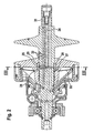
- FIG. 1 shows only a part of a conical pulley, namely the driven by a drive motor, such as an internal combustion engine drive or input side of Kegelefficiencynumschlingungsgetriebes 1.
- a drive motor such as an internal combustion engine drive or input side of Kegelusionnumschlingungsgetriebes 1.
- this input side part is assigned a complementarily trained output side part of the continuously variable Kegelusionnumschlingungsgetriebes, both parts are connected to each other via a belt in the form of a link chain 2 for torque transmission.
- the conical-pulley belt transmission 1 has on its input side a shaft 3, which in the illustrated embodiment is formed integrally with a fixed conical disk or fixed disk 4.
- This axially fixed conical disk 4 is located in the axial longitudinal direction of the shaft 3 of an axially displaceable conical disk or disk 5 adjacent.
- the axially displaceable conical disk 5 can be moved in a conventional manner in the plane of the drawing to the left, in which position the link chain 2 is in a radially inner position (which is provided with the reference numeral 2a), in which a translation of Tapered belt wrap 1 yields slowly.
- a drive motor not shown torque is in the in Fig. 1 illustrated drive-side part of the conical-pulley belt transmission via a mounted on the shaft 3 gear 6 is introduced, which is mounted on the shaft 3 via a roller bearing in the form of an axial and radial forces receiving ball bearing 7, which on the shaft 3 via a disc 8 and a shaft nut 9 is determined.
- a torque sensor 10 is disposed between the gear 6 and the axially displaceable conical disk 5, which is associated with a Sp Drettinkonfiguration 13 provided with an axially fixed spreader 11 and an axially displaceable spreader 12. Between the two expansion discs 11, 12 rolling elements are arranged for example in the form of the balls 14 shown.
- the torque sensor 10 has two pressure chambers 15, 16, of which the first pressure chamber 15 is provided for pressurizing fluid in response to the introduced torque and the second pressure chamber 16 is supplied with pressure medium, depending on the ratio of the transmission.
- a piston / cylinder unit 17 For generating the contact pressure with which the link chain 2 is acted upon by a normal force between the axially fixed conical disk 4 and the axially displaceable conical disk 5 is, a piston / cylinder unit 17 is provided which has two pressure chambers 18, 19.
- the first pressure chamber 18 is the translation-dependent change of the loading of the plate link chain 2 and the second pressure chamber 19 is used in conjunction with the torque-dependent controlled pressure chamber 15 of the torque sensor 10 to increase or decrease the contact pressure with which the link chain 2 between the conical disks 4, 5 is acted upon ,
- the shaft 3 has to supply pressure to the pressure chambers three channels 20, is fed via the pressure medium from a pump not shown in the pressure chambers. Via an outlet-side channel 21, the pressure medium can flow out of the shaft 3 and be supplied to the circuit again.
- the application of the pressure chambers 15, 16, 18, 19 leads to a torque and translation-dependent displacement of the axially displaceable conical disk 5 on the shaft 3.
- the shaft 3 has to receive the displaceable conical disk 5 centering 22, which serves as a sliding seat for the displaceable conical disk. 5 serve.
- the conical disk belt transmission 1 in the region of the bearing points of the conical disk 5 on the shaft 3 each have a noise damper 23.
- the noise damping device may have a ring body and a damping insert or only consist of a damping insert.
- FIG. 1 Reference numerals used also refer to the substantially comparable features of FIG. 2 , The figures are therefore to be regarded as a unit. For the sake of clarity, in FIG. 2 only those reference numerals are used which are above those of FIG. 1 go out.
- FIG. 2 is now the middle of the three channels 20 designed according to the invention. It can be seen that these the central channel 20 forming hole 24, as a blind hole from the FIG. 1 and 2 is made on the right side, is significantly shorter than in FIG. 1 , Such blind holes are expensive to manufacture and require a very high degree of accuracy in manufacturing. The manufacturing effort and the requirements with regard to process reliability increase disproportionately with the length. The shortening of such a hole thus has a favorable z. B. on the manufacturing costs.
- the transverse bore 25 branches off, several of which can be arranged distributed around the circumference.
- this transverse bore 25 is shown as a radial bore; However, it can also be manufactured at a different angle than inclined bore.
- the bore 25 penetrates the lateral surface of the shaft 3 at a location which is independent of the operating state, ie z. B. of the set translation, in an area that is always covered by the travel plate 5.
- the shaft 3 By laying the transverse bore 25 in the overlap region of the spacer plate 5, the shaft 3 can be made axially shorter, which space can be saved. In addition, the shortening of the shaft 3 can also result in a reduction in load.
- the mouth of the channel or the transverse bore 25 can be arranged, for example, in the region of the recess 26 which is adjacent to the centering surface 22 of the shaft. This can be particularly advantageous if the toothing 27, which axially displaceable but the spacer plate 5 rotatably connected to the shaft 3, for example, is highly stressed by the torque transmission.
- the loading of the toothing 27 will not be the most critical design criterion, so that the mouth of the bore 25 can be placed in the region of this toothing, as in FIG. 2 is shown.
- the area moment of inertia is greater at this point, while the critical fiber which is disturbed by the transverse bore 25, remains at approximately constant radius. This results in a significant reduction in the stresses in the critical area around the mouth of the transverse bore 25 between the teeth of the teeth 27.
- the supply of hydraulic fluid is in the FIGS.
- control bores 30 are exposed, so that the associated therewith, with a stopper 31 axially sealed channel 20 and the communicating with him via a channel not shown pressure chamber 16 are depressurized or have only ambient pressure.
- spacer disk 5 is moved to the fixed disk 4, it passes over the control bores 30, wherein from a certain way the chamber 29 comes to rest over the mouths of the control bores 30.
- the chamber 29 comes to rest over the mouths of the control bores 30.
- there is a dependent on the moment high pressure which is then brought via the control bores 30 and the channel 20 in the pressure chamber 16 so that there is also high pressure. In this way, two switching states are realized, which control the contact force translation-dependent.
- a plate spring 32 is provided which brings the travel disc 5 in a predetermined axial position in the pressureless state of the transmission 1, whereby a ratio of the transmission 1 can be adjusted, which prevents excessive load, for example when towing the vehicle.
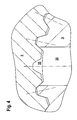
- FIG. 3 shows a section along the line III-III of FIG. 2 , wherein in the upper and lower half of the figure each have a different embodiment of the transverse bore and the channel 25 is shown.
- each per channel 33 attributable up to three teeth can be done several times on the circumference to represent the required total flow area can.
- this is done z. B. three times on the circumference with a uniform angular pitch and a divisible by three teeth z. B. at 30 teeth.
- the travel plate 5 When mounting the travel plate 5 on the shaft 3, it should be noted that the travel plate 5 is assigned in the correct angular position to the fixed disk 4 so as to ensure the required cross section of the channel 33.
- FIG. 6 Again, three different channel arrangements are shown, at A must be paid to the correct installation, while at B and C by design measures incorrect assembly can be prevented.
- this embodiment can be distributed several times around the circumference in order to obtain the required flow cross section, as well as the arrangements according to B and C.
- said expression can be produced particularly economically by virtue of the fact that the tool for rolling off the internal toothing of the spacer disk 5 has only 10 teeth plus the tool design for the two corresponding teeth and a correspondingly small diameter, so that the tool is manufactured three times in analogy to a planetary gear rotates in the bore of the spacer disk 5 and thereby brings the total originally 30 teeth minus the three times formed on the circumference special design (the number of teeth is only an example).
- the invention is advantageously applicable to all CVT disc sets with oil guide to the piston / cylinder unit 17 through the spacer plate 5 in the region of the toothing 27, in particular at high transmission torques.
- the invention is also applicable to the corresponding point of the output-side conical disk set, not shown.
Landscapes
- Engineering & Computer Science (AREA)
- General Engineering & Computer Science (AREA)
- Mechanical Engineering (AREA)
- Transmissions By Endless Flexible Members (AREA)
- Automobile Manufacture Line, Endless Track Vehicle, Trailer (AREA)
- Pulleys (AREA)
Abstract
Description
Die Erfindung betrifft ein Automatgetriebe in Form eines Kegelscheibenumschlingungsgetriebes, wie es beispielsweise aus der
So ein Kegelscheibenumschlingungsgetriebe ist aus der gattungsgemäßen
Automatgetriebe im weiteren Sinne sind Kennungswandler, deren momentane Übersetzung sich selbständig in Abhängigkeit von momentanen oder zu erwartenden Betriebszuständen, wie zum Beispiel Teillast, Schub und Umgebungsparameter, wie zum Beispiel Temperatur, Luftdruck, Luftfeuchtigkeit, stufenweise oder stufenlos verändert. Zu ihnen gehören solche Kennungswandler, die auf einem elektrischen, pneumatischen, hydrodynamischen, hydrostatischen Prinzip oder auf einem aus diesen Prinzipien gemischten Prinzip beruhen.Automatic transmissions in the broader sense are identification transducers whose instantaneous transmission varies independently depending on current or expected operating conditions, such as partial load, thrust and environmental parameters, such as temperature, air pressure, humidity, stepwise or continuously. These include those characteristic transformers which are based on an electric, pneumatic, hydrodynamic, hydrostatic principle or on a principle mixed from these principles.
Die Automatisierung bezieht sich auf die verschiedensten Funktionen, wie zum Beispiel das Anfahren, die Übersetzungswahl, die Art der Übersetzungsveränderung bei verschiedene Betriebssituationen, wobei unter Art der Übersetzungsveränderung zum Beispiel das Schalten von einzelnen Stufen nacheinander, das Überspringen von Schaltstufen und die Geschwindigkeit der Verstellung verstanden werden kann.The automation refers to a variety of functions, such as the start, the translation choice, the nature of the ratio change in various operating situations, where understood by type of translation change, for example, the switching of individual stages in succession, the skipping of switching stages and the speed of adjustment can be.
Der Wunsch nach Komfort, Sicherheit und vertretbarem Bauaufwand bestimmt den Automatisierungsgrad d. h. wie viele Funktionen selbständig ablaufen.The desire for comfort, safety and reasonable construction costs determines the degree of automation d. H. how many functions run independently.
In der Regel kann der Fahrer manuell in den automatischen Ablauf eingreifen oder ihn für einzelne Funktionen begrenzen.As a rule, the driver can intervene manually in the automatic sequence or limit it for individual functions.
Automatgetriebe im engeren Sinne, wie sie heute vor allem im Fahrzeugbau verwendet werden, haben in der Regel folgenden Aufbau:Automatic transmissions in the narrower sense, as they are used today mainly in vehicle construction, usually have the following structure:
Auf der Antriebsseite des Getriebes befindet sich eine Anfahreinheit in Form einer regelbaren Kupplung, zum Beispiel einer nassen oder trockenen Reibungskupplung, einer hydrodynamischen Kupplung oder einem hydrodynamischen Wandler.On the drive side of the transmission there is a starting unit in the form of a controllable clutch, for example a wet or dry friction clutch, a hydrodynamic clutch or a hydrodynamic converter.
Zu einem hydrodynamischen Wandler wird häufig eine Überbrückungskupplung parallel zum Pumpen- und Turbinenteil geschaltet, welche durch direkte Kraftübertragung den Wirkungsgrad steigert und durch definierten Schlupf bei kritischen Drehzahlen die Schwingung dämpft.To a hydrodynamic converter, a lock-up clutch is often connected in parallel to the pump and turbine part, which increases the efficiency by direct power transmission and attenuates the vibration by defined slip at critical speeds.
Die Anfahreinheit treibt ein mechanisches, stufenloses oder gestuftes Wechselgetriebe an, das eine Vorwärts-/Rückwärtsfahreinheit, eine Haupt-, Bereichs-, Splitgruppe und/oder einen Variator enthalten kann. Zahnradgetriebegruppen werden, je nach Anforderungen an Laufruhe, Platzverhältnisse und Übertragungsmöglichkeiten, in Vorgelege- oder Planetenbauweise mit Gerad- oder Schrägverzahnung ausgelegt.The starter unit drives a mechanical, continuously variable or stepped change gear that may include a forward / reverse unit, a main, range, split group and / or a variator. Depending on the requirements for smooth running, space and transmission options, gearbox groups are designed in countershaft or planetary design with straight or helical gearing.
Das Ausgangselement des mechanischen Getriebes, eine Welle oder ein Zahnrad, treibt direkt oder indirekt über Zwischenwellen bzw. eine Zwischenstufe mit einer konstanten Übersetzung auf ein Differentialgetriebe, das als separates Getriebe gestaltet sein kann oder ein integrierter Bestandteil des Automatgetriebes ist. Grundsätzlich eignet sich das Getriebe für Längs- und Quereinbau im Fahrzeug.The output element of the mechanical transmission, a shaft or a gear, drives directly or indirectly via intermediate shafts or an intermediate stage with a constant ratio to a differential gear, which may be designed as a separate transmission or is an integral part of the automatic transmission. Basically, the transmission is suitable for longitudinal and transverse installation in the vehicle.
Zur Verstellung der Übersetzung im mechanischen Getriebe sind hydrostatische, pneumatische und/oder elektrische Stellglieder vorgesehen. Eine Hydraulikpumpe, die nach dem Verdrängungsprinzip arbeitet, liefert Drucköl für die Anfahreinheit, insbesondere die hydrodynamische Einheit, für die hydrostatischen Stellelemente des mechanischen Getriebes und für die Schmierung und Kühlung des Systems. Je nach erforderlichem Druck und Fördervolumen kommen Zahnradpumpen, Schraubenpumpen, Flügelzellenpumpen und Kolbenpumpen, letztere meistens in radialer Bauart, in Frage. In der Praxis haben sich Zahnradpumpen und Radialkolbenpumpen für diesen Zweck durchgesetzt, wobei die Zahnradpumpen wegen ihres geringen Bauaufwandes und die Radialkolbenpumpe wegen des höheren Druckniveaus und der besseren Regelbarkeit Vorteile bieten.To adjust the translation in the mechanical transmission hydrostatic, pneumatic and / or electrical actuators are provided. A displacement-type hydraulic pump supplies pressure oil to the starter unit, especially the hydrodynamic unit, to the hydrostatic actuators of the mechanical gearbox and to the lubrication and cooling of the system. Depending on the required pressure and delivery volume are gear pumps, screw pumps, vane pumps and piston pumps, the latter mostly in radial design, in question. In practice, gear pumps and radial piston pumps have prevailed for this purpose, the gear pumps offer advantages because of their low construction costs and the radial piston pump because of the higher pressure levels and better controllability.
Die Hydraulikpumpe kann an einer beliebigen Stelle des Getriebes an einer ständig von der Antriebseinheit angetriebenen Haupt- oder Nebenwelle angeordnet sein.The hydraulic pump can be arranged at any point of the transmission on a constantly driven by the drive unit main or secondary shaft.
Es sind stufenlose Automatgetriebe bekannt, bestehend aus einer Anfahreinheit, einem Planetenwendegetriebe als Vorwärts-/Rückwärtsfahreinheit, einer Hydraulikpumpe, einem Variator, einer Zwischenwelle und einem Differential. Der Variator wiederum besteht aus zwei Kegelscheibenpaaren und einem Umschlingungsorgan. Jedes Kegelscheibenpaar besteht aus einer in axialer Richtung verschiebbaren zweiten Kegelscheibe. Zwischen diesen Kegelscheibenpaaren läuft das Umschlingungsorgan, zum Beispiel ein Schubgliederband, eine Zugkette oder ein Riemen. Über die Verstellung der zweiten Kegelscheibe ändert sich der Laufradius des Umschlingungsorgans und somit die Übersetzung des stufenlosen Automatgetriebes.Stepless automatic transmissions are known, consisting of a starter unit, a planetary gear transmission as a forward / reverse drive unit, a hydraulic pump, a variator, an intermediate shaft and a differential. The variator in turn consists of two conical disk pairs and a belt. Each conical disk pair consists of a second conical disk which can be displaced in the axial direction. Between these conical disk pairs runs the belt, for example a push belt, a Pull chain or a belt. About the adjustment of the second conical disk, the radius of the Umschlingungsorgans and thus the ratio of the continuously variable automatic transmission changes.
Stufenlose Automatgetriebe erfordern ein hohes Druckniveau, um die Kegelscheiben des Variators in allen Betriebspunkten mit der gewünschten Geschwindigkeit verstellen zu können und außerdem mit einem genügenden Basisanpressdruck weitgehend verschleißfrei das Drehmoment zu übertragen.Infinitely variable automatic transmissions require a high level of pressure in order to be able to adjust the variator's conical disks at the desired speed at all operating points and, moreover, to transmit the torque largely wear-free with a sufficient basic contact pressure.
Eine der Erfindung zugrunde liegende Teilaufgabe liegt darin, die mittels eines hydraulischen Mediums dargestellte Kraftübertragung zu verbessern. Eine weitere Teilaufgabe liegt darin, die Teilefertigung zu vereinfachen und auch damit die Herstellungskosten günstig zu beeinflussen. Eine weitere Teilaufgabe der Erfindung liegt darin, die Betriebsfestigkeit von Bauteilen zu erhöhen und somit die Lebensdauer eines derartigen Automatgetriebes zu verlängern. Eine weitere Teilaufgabe der Erfindung liegt darin begründet, die Drehmomentübertragungsfähigkeit eines derartigen Getriebes zu erhöhen bzw. größere Kräfte durch die Bauteile des Getriebes übertragen zu können.A sub-task on which the invention is based is to improve the transmission of force represented by means of a hydraulic medium. Another sub-task is to simplify the parts production and also to influence the production costs low. Another object of the invention is to increase the durability of components and thus to extend the life of such an automatic transmission. Another sub-task of the invention is based on increasing the torque transmission capability of such a transmission or to be able to transmit greater forces through the components of the transmission.
Diese Aufgabenteile werden durch die in den Ansprüchen dargelegte sowie in der Beschreibung auch im Zusammenhang mit den Figuren erläuterte Erfindung mit deren Weiterbildungen gelöst.These objects are achieved by the invention set forth in the claims and in the description also in connection with the figures with their developments.
Dadurch wird beispielsweise eine Verkürzung der Zuführbohrung für das hydraulische Medium erreicht, die so wirtschaftlicher und mit erhöhter Prozesssicherheit gefertigt werden kann.As a result, for example, a shortening of the supply bore for the hydraulic medium is achieved, which can be manufactured more economically and with increased process reliability.
Durch diese Anordnung der Bohrung mitten in der Steckverzahnung bildet diese praktisch eine Art Rippen um die hoch beanspruchten Bohrungen, wodurch eine erhebliche Festigkeitssteigerung erzielbar ist, da die Spannungen im kritischen Bereich um den Bohrungsaustritt aus der Mantelfläche der Welle zwischen den Zähnen erheblich verringert werden.This arrangement of the hole in the middle of the splines this practically forms a kind of ribs around the highly stressed holes, creating a significant increase in strength can be achieved because the stresses in the critical area around the hole exit from the lateral surface of the shaft between the teeth are significantly reduced.
Es kann sich als zweckmäßig erweisen, wenn der Zahn im Bereich des Bohrungsaustritts entfällt, wobei es weiterhin vorteilhaft sein kann, zwei dem Bohrungsaustritt benachbarte Zähne am Innendurchmesser der Wegscheibe entfallen zu lassen.It may prove expedient if the tooth is omitted in the region of the bore outlet, wherein it may also be advantageous to omit two teeth adjacent to the bore exit on the inner diameter of the spacer plate.
Allgemein kann es bei einem Kegelscheibenumschlingungsgetriebe nach der Erfindung von Vorteil sein, mehrere Bohrungsaustritte am Umfang vorzusehen, wobei die Bohrungsaustritte bevorzugt gleichmäßig über den Umfang verteilt angeordnet werden können.In general, in a conical-pulley transmission according to the invention, it may be advantageous to provide a plurality of bore outlets on the circumference, wherein the bore outlets may preferably be distributed uniformly over the circumference.
Bei einem erfindungsgemäßen Kegelscheibenumschlingungsgetriebe werden bevorzugt die Wegscheibe und die Festscheibe eines Kegelscheibenpaares in Umfangsrichtung einander zugeordnet angeordnet.In a conical-pulley belt transmission according to the invention, the travel disk and the fixed disk of a pair of conical disks are preferably arranged so as to be associated with one another in the circumferential direction.
Hierzu kann es vorteilhaft sein, wenn im Bereich der Innenverzahnung der Wegscheibe eine Erhöhung vorgesehen ist, die an der Stelle des entfallenen Zahnes der Welle eingreift, und/oder im Bereich des Außendurchmessers der Welle zumindest eine Erhöhung vorgesehen ist, die im Bereich der entfallenen Zähne der Wegscheibe zu liegen kommt, wodurch konstruktiv eine Fehlmontage ausgeschlossen werden kann.For this purpose, it may be advantageous if an elevation is provided in the region of the internal toothing of the spacer, which engages at the location of the missing tooth of the shaft, and / or at least one elevation is provided in the region of the outer diameter of the shaft, in the region of the canceled teeth the disk comes to rest, which constructively a wrong assembly can be excluded.
Weiterhin bezieht sich die Erfindung auf ein Verfahren zum Herstellen eines erfindungsgemäßen Kegelscheibenumschlingungsgetriebes, wobei das Werkzeug zur Herstellung der Außenverzahnung der Welle und/oder der Innenverzahnung der Wegscheibe - in Umfangsrichtung betrachtet - nur einen Teil des Profils erzeugt und zur Fertigung eines weiteren Teils winkelmäßig verdreht wird.Furthermore, the invention relates to a method for producing a conical-pulley transmission according to the invention, wherein the tool for producing the external toothing of the shaft and / or the internal toothing of the spacer - viewed in the circumferential direction - only generates part of the profile and is angularly rotated to produce another part ,
Des Weiteren bezieht sich die Erfindung auf ein Fahrzeug mit einem erfindungsgemäßen Getriebe.Furthermore, the invention relates to a vehicle with a transmission according to the invention.
Die Erfindung wird im Folgenden anhand schematischer Zeichnungen beispielsweise mit weiteren Einzelheiten erläutert.The invention will be explained below with reference to schematic drawings, for example, with further details.
Es stellen dar:
-
Figur 1 eine Teilansicht eines Kegelscheibenumschlingungsgetriebes, -
Figur 2 eine im Wesentlichen derFigur 1 entsprechende Darstellung einer Ausführungsform der Erfindung, -
Figur 3Figur 2 , -
Figur 4 die Einzelheit IV derFigur 3 -
Figur 5Figur 3 -
Figur 6 weitere mögliche Ausführungsformen gemäß Schnitt III-III
-
FIG. 1 a partial view of a belt pulley, -
FIG. 2 a substantially theFIG. 1 corresponding representation of an embodiment of the invention, -
FIG. 3 a partial section along the line III-III ofFIG. 2 . -
FIG. 4 the detail IV ofFIG. 3 . -
FIG. 5 the detail V ofFIG. 3 -
FIG. 6 Other possible embodiments according to section III-III
Bei der Darstellung nach
Die axial verlagerbare Kegelscheibe 5 kann in an sich bekannter Weise in der Zeichnungsebene auch nach links verlagert werden, wobei sich in dieser Stellung die Laschenkette 2 in einer radial inneren Stellung befindet (die mit dem Bezugszeichen 2a versehen ist), bei der sich eine Übersetzung des Kegelscheibenumschlingungsgetriebes 1 ins Langsame ergibt.The axially displaceable
Das von einem nicht näher dargestellten Antriebsmotor bereit gestellte Drehmoment wird in den in
Ein über das Zahnrad 6 eingeleitetes Drehmoment führt zur Ausbildung eines Drehwinkels zwischen der axial feststehenden Spreizscheibe 11 und der axial verlagerbaren Spreizscheibe 12, was zu einer axialen Verlagerung der Spreizscheibe 12 führt und zwar aufgrund von an dieser angeordneten Anlauframpen, auf die die Kugeln 14 auflaufen und so für einen axialen Versatz der Spreizscheiben zueinander sorgen.An introduced via the gear 6 torque leads to the formation of a rotational angle between the axially fixed
Der Drehmomentfühler 10 besitzt zwei Druckräume 15, 16, von denen der erste Druckraum 15 für eine Beaufschlagung mit Druckmittel in Abhängigkeit von dem eingeleiteten Drehmoment vorgesehen ist und der zweite Druckraum 16 mit Druckmittel versorgt wird und zwar in Abhängigkeit von der Übersetzung des Getriebes.The
Zur Erzeugung der Anpresskraft, mit der die Laschenkette 2 zwischen der axial feststehenden Kegelscheibe 4 und der axial verlagerbaren Kegelscheibe 5 mit einer Normalkraft beaufschlagt wird, ist eine Kolben/Zylindereinheit 17 vorgesehen, die zwei Druckräume 18, 19 besitzt. Der erste Druckraum 18 dient der übersetzungsabhängigen Veränderung der Beaufschlagung der Laschenkette 2 und der zweite Druckraum 19 dient in Verbindung mit dem drehmomentabhängig gesteuerten Druckraum 15 des Drehmomentfühlers 10 zur Erhöhung oder Verringerung der Anpresskraft, mit der die Laschenkette 2 zwischen den Kegelscheiben 4, 5 beaufschlagt wird.For generating the contact pressure with which the link chain 2 is acted upon by a normal force between the axially fixed conical disk 4 and the axially displaceable
Die Welle 3 besitzt zur Druckmittelversorgung der Druckräume drei Kanäle 20, über die von einer nicht dargestellten Pumpe Druckmittel in die Druckräume eingespeist wird. Über einen auslassseitigen Kanal 21 kann das Druckmittel aus der Welle 3 abfließen und dem Kreislauf wieder zugeführt werden.The
Die Beaufschlagung der Druckräume 15, 16, 18, 19 führt zu einer momenten- und übersetzungsabhängigen Verschiebung der axial verlagerbaren Kegelscheibe 5 auf der Welle 3. Die Welle 3 besitzt zur Aufnahme der verlagerbaren Kegelscheibe 5 Zentrierflächen 22, die als Schiebesitz für die verlagerbare Kegelscheibe 5 dienen.The application of the
Wie es anhand der
Die in
In
Im Bereich des Grundes dieser Bohrung 24 zweigt die Querbohrung 25 ab, von denen mehrere am Umfang verteilt angeordnet sein können. Im dargestellten Fall ist diese Querbohrung 25 als radiale Bohrung dargestellt; sie kann jedoch auch in einem anderen Winkel als Schrägbohrung gefertigt werden. Die Bohrung 25 durchdringt die Mantelfläche der Welle 3 an einer Stelle, die unabhängig vom Betriebszustand, also z. B. von der eingestellten Übersetzung, in einem Bereich liegt, der stets von der Wegscheibe 5 überdeckt wird.In the region of the bottom of this bore 24, the transverse bore 25 branches off, several of which can be arranged distributed around the circumference. In the case shown, this transverse bore 25 is shown as a radial bore; However, it can also be manufactured at a different angle than inclined bore. The
Durch das Verlegen der Querbohrung 25 in den Überdeckungsbereich der Wegscheibe 5 kann die Welle 3 axial kürzer ausgeführt werden, wodurch Bauraum eingespart werden kann. Außerdem kann sich durch die Verkürzung der Welle 3 auch eine Belastungsreduzierung ergeben.By laying the transverse bore 25 in the overlap region of the
Die Mündung des Kanals bzw. der Querbohrung 25 kann dabei beispielsweise im Bereich der Ausdrehung 26, der der Zentrierfläche 22 der Welle benachbart ist, angeordnet werden. Dies kann insbesondere vorteilhaft sein, wenn die Verzahnung 27, die die Wegscheibe 5 axial verschiebbar jedoch drehfest mit der Welle 3 verbindet, beispielsweise durch die Drehmomentübertragung hoch beansprucht ist.The mouth of the channel or the
In vielen Fällen wird jedoch die Belastung der Verzahnung 27 nicht das kritischste Auslegungskriterium sein, so dass die Mündung der Bohrung 25 in den Bereich dieser Verzahnung gelegt werden kann, wie dies in
Weiterhin ist in
Im unteren Bereich, dessen Ausschnitt IV in
Wenn ein derartiger Querschnitt des Kanals 33 nicht ausreichend ist, können zusätzlich die zwei benachbarten radial nach innen ragenden Zähne der Wegscheibe 5 entfallen, wie dies im Bereich V und vergrößert in
Der Entfall der jeweils pro Kanal 33 entfallenden bis zu drei Zähne kann mehrfach am Umfang erfolgen, um den erforderlichen Gesamtströmungsquerschnitt darstellen zu können. Vorteilhafterweise erfolgt dies z. B. dreimal am Umfang mit gleichmäßiger Winkelteilung und einer durch drei teilbaren Zähnezahl z. B. bei 30 Zähnen.The elimination of the each per
Bei der Montage der Wegscheibe 5 auf der Welle 3 ist zu beachten, dass die Wegscheibe 5 in der richtigen Winkelposition zur Festscheibe 4 zugeordnet wird, um so den erforderlichen Querschnitt des Kanals 33 sicher zu stellen.When mounting the
In
Bei A ist nochmals die Anordnung gemäß
Bei B ist eine konstruktive Lösung dargestellt, die eine falsche Zuordnung bei der Montage ausschließt. Hierzu wird erfindungsgemäß in der Innenverzahnung der Wegscheibe 5 eine Erhöhung 34 genau an der Stelle zwischen zwei ursprünglich vorhandenen Zähnen vorgesehen, an der bei Falschverbau ein Zahn der Welle 3 zu liegen käme.At B, a constructive solution is shown, which excludes an incorrect assignment during assembly. For this purpose, according to the invention in the internal toothing of the
Bei C ist eine Lösung dargestellt, die auf der Welle 3 eine oder zwei Erhöhungen 35 in der Doppellücke an den Stellen vorgesehen werden, an denen bei versuchtem Falschverbau Zähne der Wegscheibe 5 zu liegen kämen.At C, a solution is shown, which are provided on the
Erfindungsgemäß kann die genannte Ausprägung besonders wirtschaftlich dadurch hergestellt werden, dass das Werkzeug zum Abwälzstoßen der Innenverzahnung der Wegscheibe 5 nur 10 Zähne zuzüglich der Werkzeuggestaltung für die beiden entfallenden Zähne und einen entsprechend kleinen Durchmesser aufweist, so dass das Werkzeug bei der Fertigung analog einem Planetenrad dreimal in der Bohrung der Wegscheibe 5 rotiert und dabei die insgesamt ursprünglich 30 Zähne abzüglich der dreimal am Umfang ausgebildeten besonderen Gestaltung einbringt (die Anzahl der Zähne dient lediglich als Beispiel).According to the invention, said expression can be produced particularly economically by virtue of the fact that the tool for rolling off the internal toothing of the
Analog wird für die Fertigung der Außenverzahnung der Welle 3 ein Werkzeug mit ursprünglich 10, 20, 30 oder entsprechend mehr Zähnen einschließlich der entfallenden Zähne verwendet. Damit entstehen außer den einmaligen Werkzeugkosten, praktisch keine zusätzlichen Stückkosten.Analogously, a tool with originally 10, 20, 30 or correspondingly more teeth including the associated teeth is used for the production of the external teeth of the
Die Erfindung ist vorteilhaft anwendbar bei allen CVT-Scheibensätzen mit Ölführung zur Kolben-/Zylindereinheit 17 durch die Wegscheibe 5 im Bereich der Verzahnung 27, insbesondere bei hohen Getriebemomenten.The invention is advantageously applicable to all CVT disc sets with oil guide to the piston /
Die Erfindung ist ebenfalls anwendbar an der entsprechenden Stelle des nicht dargestellten abtriebsseitigen Kegelscheibensatzes.The invention is also applicable to the corresponding point of the output-side conical disk set, not shown.
- 11
- Kegelscheibenumschlingungsgetriebecone pulley
- 22
- Laschenkettelink chain
- 2a2a
- radial innere Stellung der Laschenketteradially inner position of the link chain
- 33
- Wellewave
- 44
- Festscheibehard disk
- 55
- Wegscheibemovable disk
- 66
- Zahnradgear
- 77
- Kugellagerball-bearing
- 88th
- Scheibedisc
- 99
- Wellenmuttershaft nut
- 1010
- Drehmomentfühlertorque sensor
- 1111
- axial feststehende Spreizscheibeaxially fixed expanding disc
- 1212
- axial verlagerbare Spreizscheibeaxially displaceable expansion disc
- 1313
- SpreizscheibenkonfigurationSpreizscheibenkonfiguration
- 1414
- Kugelnroll
- 1515
- erster Druckraumfirst pressure chamber
- 1616
- zweiter Druckraumsecond pressure chamber
- 1717
- Kolben-/ZylindereinheitPiston / cylinder unit
- 1818
- erster Druckraumfirst pressure chamber
- 1919
- zweiter Druckraumsecond pressure chamber
- 2020
- (drei) Kanäle (Einspeisung)(three) channels (feed)
- 2121
- Kanal (auslassseitig)Channel (outlet side)
- 2222
- Zentrierflächecentering
- 2323
- GeräuschdämpfungseinrichtungSilencing device
- 2424
- (zentrale) Bohrung(central) bore
- 2525
- Querbohrung(en)Transverse bore (s)
- 2626
- Ausdrehungrecess
- 2727
- Verzahnunggearing
- 2828
- Verbindungsbohrungenconnecting bores
- 2929
- Hohlraum / KammerCavity / chamber
- 3030
- Steuerbohrungendrillings
- 3131
- StopfenPlug
- 3232
- TellerfederBelleville spring
- 3333
- Kanalchannel
- 3434
- Erhöhungincrease
- 3535
- Erhöhungincrease
Claims (9)
- Continuously variable cone-pulley transmission (1) with drive-input-side and drive-output-side cone-pulley pairs which have in each case one fixed pulley (4) and one moving pulley (5) which are arranged in each case on a drive-input-side and on a drive-output-side shaft (3) and which can be connected via an endless chain-belt (2) for torque transmission, with at least one of the shafts (3) having at least one bore (20) which extends in the longitudinal direction of the shaft (3) and from which extends at least one bore (25), such as an oblique or transverse bore, which extends to the lateral surface of the shaft (3) and the outlet of which is arranged on the lateral surface in a region which is covered by the moving pulley (5) regardless of the axial position of the latter, with at least one fixed pulley (4) being connected to the shaft (3) in a unipartite fashion and with the moving pulley (5) being connected to the shaft (3) in a rotationally fixed yet axially movable manner by means of a toothing (27), and with the outlet of the bore (25) out of the lateral surface being arranged in the region of the toothing (27), characterized in that one tooth of the toothing (27) is omitted in the region of the bore outlet.
- Continuously variable cone-pulley transmission (1) according to Claim 1, characterized in that two teeth adjacent to the bore outlet on the inner diameter of the moving pulley (5) are omitted.
- Continuously variable cone-pulley transmission (1) according to one of the preceding claims, characterized in that a plurality of bore outlets are provided on the periphery.
- Continuously variable cone-pulley transmission (1) according to Claim 3, characterized in that the bore outlets are distributed uniformly over the periphery.
- Continuously variable cone-pulley transmission (1) according to one of the preceding claims, characterized in that the moving pulley (5) and the fixed pulley (4) of a cone-pulley pair are arranged so as to be assigned to one another in the circumferential direction.
- Continuously variable cone-pulley transmission (1) according to Claim 5, characterized in that an elevation (34) is provided in the region of the inner toothing of the moving pulley, which elevation (34) engages at the point of the omitted tooth of the shaft (3).
- Continuously variable cone-pulley transmission (1) according to one of Claims 5 or 6, characterized in that at least one elevation (35) is provided in the region of the outer diameter of the shaft (3), which elevation (35) comes to rest in the region of the omitted teeth of the moving pulley (5).
- Method for producing a continuously variable cone-pulley transmission (1) according to one of the preceding claims, characterized in that the tool for producing the outer toothing of the shaft (3) and/or the inner toothing of the moving pulley (5) - as viewed in the circumferential direction - generates only a part of the profile, and is rotated by an angle to produce a further part.
- Vehicle, characterized by a transmission according to one of the preceding claims.
Applications Claiming Priority (2)
| Application Number | Priority Date | Filing Date | Title |
|---|---|---|---|
| DE102004040204 | 2004-08-19 | ||
| PCT/DE2005/001413 WO2006018010A2 (en) | 2004-08-19 | 2005-08-11 | Conical pulley flexible drive transmission, method for producing the same and vehicle comprising said transmission |
Publications (2)
| Publication Number | Publication Date |
|---|---|
| EP1781969A2 EP1781969A2 (en) | 2007-05-09 |
| EP1781969B1 true EP1781969B1 (en) | 2008-10-01 |
Family
ID=35079190
Family Applications (1)
| Application Number | Title | Priority Date | Filing Date |
|---|---|---|---|
| EP05771467A Not-in-force EP1781969B1 (en) | 2004-08-19 | 2005-08-11 | Conical pulley flexible drive transmission, method for producing the same and vehicle comprising said transmission |
Country Status (8)
| Country | Link |
|---|---|
| US (1) | US7789779B2 (en) |
| EP (1) | EP1781969B1 (en) |
| JP (1) | JP2008510112A (en) |
| KR (1) | KR20070052741A (en) |
| CN (1) | CN100595455C (en) |
| AT (1) | ATE409822T1 (en) |
| DE (2) | DE112005002600A5 (en) |
| WO (1) | WO2006018010A2 (en) |
Families Citing this family (10)
| Publication number | Priority date | Publication date | Assignee | Title |
|---|---|---|---|---|
| JP4453740B2 (en) * | 2007-10-25 | 2010-04-21 | トヨタ自動車株式会社 | Belt-type continuously variable transmission shaft, stationary sheave for continuously variable transmission, manufacturing method thereof and continuously variable transmission |
| DE202009003671U1 (en) | 2009-03-17 | 2009-05-28 | Getrag Getriebe- Und Zahnradfabrik Hermann Hagenmeyer Gmbh & Cie Kg | Shaft assembly for a transmission |
| DE102011015269A1 (en) | 2010-04-15 | 2011-12-15 | Schaeffler Technologies Gmbh & Co. Kg | Taper disk-continuously variable transmission for use in drive train of motor vehicle, has sensor chamber connected with pressure discharging chamber over control edge of sensor and channel that is formed between shaft and sensor piston |
| CN103477120B (en) * | 2011-03-23 | 2016-03-09 | 丰田自动车株式会社 | Variable v-belt drive |
| CN103459889A (en) * | 2011-03-25 | 2013-12-18 | 丰田自动车株式会社 | Belt-type continuously variable transmission |
| JP6020720B2 (en) * | 2013-06-07 | 2016-11-02 | トヨタ自動車株式会社 | Belt type continuously variable transmission |
| EP3181931B1 (en) * | 2015-12-15 | 2018-03-28 | Spicer Gelenkwellenbau GmbH | Length balancing for a drive shaft |
| WO2019219243A1 (en) * | 2018-05-14 | 2019-11-21 | Sew-Eurodrive Gmbh & Co. Kg | Brake assembly for an electric motor |
| US11105330B2 (en) | 2018-08-29 | 2021-08-31 | Borgwarner Inc. | Power transmitting component having a shaft with a circumferential channel communicating fluid between a shaft-driven pump and a feed conduit formed in the shaft |
| US11754151B2 (en) * | 2018-10-22 | 2023-09-12 | Jatco Ltd | Continuously variable transmission for vehicle |
Family Cites Families (47)
| Publication number | Priority date | Publication date | Assignee | Title |
|---|---|---|---|---|
| US1541007A (en) * | 1921-07-18 | 1925-06-09 | William H Thiemer | Slip-end spline connection for universal joints and the like |
| US1715077A (en) * | 1928-07-18 | 1929-05-28 | Gen Motors Corp | Synchronizing transmission |
| US1982284A (en) * | 1932-08-27 | 1934-11-27 | Aero Engineering Corp | Propeller control mechanism |
| US1973702A (en) * | 1933-03-31 | 1934-09-18 | Frank V Cooke | Slip joint |
| US1963355A (en) * | 1933-05-20 | 1934-06-19 | Warner Gear Co | Method of treating gears and similar articles |
| US2451447A (en) * | 1942-02-13 | 1948-10-12 | Barber Colman Co | Hobbing machine |
| US2927510A (en) * | 1956-05-07 | 1960-03-08 | Wildhaber Ernest | Method and machine for producing toothed couplings |
| US2996131A (en) * | 1957-06-03 | 1961-08-15 | Eugene C Greenwood | Lubricant packed bumper sub |
| US3063266A (en) * | 1958-06-05 | 1962-11-13 | Birfield Eng Ltd | Mechanisms comprising a plunger sliding within a cylinder and lubrication arrangements therefor |
| US3141313A (en) * | 1963-01-28 | 1964-07-21 | Gen Electric | Torque-limiting shaft coupling assembly |
| US3242695A (en) * | 1963-12-23 | 1966-03-29 | Ford Motor Co | Slip spline lubrication system |
| US3359803A (en) * | 1965-10-12 | 1967-12-26 | Gilson Brothers Co | Torque divider |
| JPS6049162A (en) * | 1983-08-30 | 1985-03-18 | Sakai Seisakusho:Kk | Speed change v-pulley |
| US4504246A (en) * | 1983-12-14 | 1985-03-12 | Borg-Warner Corporation | Revised spline drive for metal belt CVT |
| JPS6174970A (en) * | 1984-09-18 | 1986-04-17 | Sakai Seisakusho:Kk | Speed change v-pulley |
| US4813914A (en) * | 1987-12-28 | 1989-03-21 | Borg-Warner Automotive, Inc. | Strap drive with a safety stop for reverse torques |
| JPH01203759A (en) * | 1988-02-05 | 1989-08-16 | Honda Motor Co Ltd | Spline |
| JP2589559B2 (en) * | 1988-11-11 | 1997-03-12 | 武蔵精密工業株式会社 | Mission gear |
| US5184981A (en) * | 1991-01-07 | 1993-02-09 | Wittke Ernest C | Cam loaded continuously variable transmission |
| US5064040A (en) * | 1991-02-14 | 1991-11-12 | Deere & Company | Splined clutch drum mounting |
| JP3131064B2 (en) * | 1993-01-27 | 2001-01-31 | 愛知機械工業株式会社 | Variable pulley for continuously variable transmission |
| DE4305102A1 (en) * | 1993-02-19 | 1994-08-25 | Zahnradfabrik Friedrichshafen | Device for guiding a movable disc |
| IN189939B (en) * | 1993-12-20 | 2003-05-17 | Torotrak Dev Ltd | |
| JP3341961B2 (en) * | 1994-02-28 | 2002-11-05 | 株式会社ユニシアジェックス | Shaft coupling structure |
| JP3097439B2 (en) * | 1994-03-17 | 2000-10-10 | 日産自動車株式会社 | Oil passage structure for continuously variable transmission |
| EP0707157B1 (en) * | 1994-10-13 | 2003-07-09 | Matsui Universal Joint Manufacturing Company | Method of producing a propeller shaft |
| NL1000932C2 (en) * | 1995-08-04 | 1997-02-06 | Doornes Transmissie Bv | Pulley. |
| NL1001755C2 (en) * | 1995-11-28 | 1997-05-30 | Doornes Transmissie Bv | Pulley. |
| ES2120874B1 (en) * | 1995-11-29 | 1999-06-01 | Daumal Castellon Melchor | PERFECTED ARRANGEMENT APPLICABLE TO TELESCOPIC TREES. |
| US5772520A (en) * | 1996-07-11 | 1998-06-30 | Ford Motor Company | Vented studyoke on slip-between-center driveshaft |
| DE19743675A1 (en) * | 1996-10-08 | 1998-04-09 | Luk Getriebe Systeme Gmbh | Steplessly variable power transmission |
| JP3259826B2 (en) * | 1997-01-24 | 2002-02-25 | 愛知機械工業株式会社 | Pulley oil passage structure of belt type continuously variable transmission |
| JP3248615B2 (en) * | 1997-01-24 | 2002-01-21 | 愛知機械工業株式会社 | Cylinder structure for pulley of belt type continuously variable transmission |
| JPH11141633A (en) * | 1997-11-12 | 1999-05-25 | Fuji Heavy Ind Ltd | Pulley structure for continuously variable transmission |
| DE19909347B4 (en) * | 1998-03-10 | 2012-03-29 | Schaeffler Technologies Gmbh & Co. Kg | transmission |
| DE19921750B4 (en) * | 1998-05-18 | 2012-03-08 | Schaeffler Technologies Gmbh & Co. Kg | transmission |
| DE10022846B4 (en) * | 1999-05-17 | 2013-03-28 | Schaeffler Technologies AG & Co. KG | transmission |
| JP2000346183A (en) * | 1999-06-02 | 2000-12-12 | Mitsubishi Agricult Mach Co Ltd | Lubricating structure for split pulley |
| DE10037136A1 (en) * | 1999-09-02 | 2001-03-08 | Luk Lamellen & Kupplungsbau | Continuously variable cone pulley belt contact gearbox has ring chambers on cone pulley pairs formed by the shaft, the axially displaceable cone pulley and ring-shaped disc elements |
| DE10052471B4 (en) * | 1999-11-08 | 2012-08-23 | Schaeffler Technologies Gmbh & Co. Kg | cone pulley |
| US6949854B1 (en) * | 2001-03-16 | 2005-09-27 | Michael Schlicht | Method and apparatus for a continuously variable-ratio transmission |
| DE10130388B4 (en) * | 2001-06-23 | 2011-01-13 | Zf Friedrichshafen Ag | variator |
| DE10132976A1 (en) * | 2001-07-06 | 2003-01-23 | Zf Batavia Llc | Guide device of conical pulley disc of continuously variable transmission variator has cylindrical pin that is fitted into guide groove in variator shaft, and axial guide groove in movable pulley |
| US6871719B2 (en) * | 2001-12-27 | 2005-03-29 | Torque-Traction Technologies, Inc. | Drive train member having convex splines |
| AU2003271517A1 (en) * | 2002-09-05 | 2004-04-30 | Luk Lamellen Und Kupplungsbau Beteiligungs Kg | Spherical-disk-shaped enveloping gear system |
| JP4806827B2 (en) | 2003-04-07 | 2011-11-02 | シェフラー テクノロジーズ ゲゼルシャフト ミット ベシュレンクテル ハフツング ウント コンパニー コマンディートゲゼルシャフト | Conical disk-type winding transmission and ring with protrusion |
| JP2007177955A (en) * | 2005-12-28 | 2007-07-12 | Toyota Motor Corp | Propeller shaft |
-
2005
- 2005-08-11 DE DE112005002600T patent/DE112005002600A5/en not_active Withdrawn
- 2005-08-11 AT AT05771467T patent/ATE409822T1/en not_active IP Right Cessation
- 2005-08-11 CN CN200580028582A patent/CN100595455C/en not_active Expired - Fee Related
- 2005-08-11 EP EP05771467A patent/EP1781969B1/en not_active Not-in-force
- 2005-08-11 DE DE502005005560T patent/DE502005005560D1/en active Active
- 2005-08-11 KR KR1020077001587A patent/KR20070052741A/en not_active Application Discontinuation
- 2005-08-11 WO PCT/DE2005/001413 patent/WO2006018010A2/en active IP Right Grant
- 2005-08-11 JP JP2007526198A patent/JP2008510112A/en active Pending
-
2007
- 2007-02-17 US US11/707,558 patent/US7789779B2/en active Active
Also Published As
| Publication number | Publication date |
|---|---|
| CN100595455C (en) | 2010-03-24 |
| DE112005002600A5 (en) | 2007-08-02 |
| ATE409822T1 (en) | 2008-10-15 |
| DE502005005560D1 (en) | 2008-11-13 |
| WO2006018010A2 (en) | 2006-02-23 |
| WO2006018010A3 (en) | 2006-05-18 |
| US20070298917A1 (en) | 2007-12-27 |
| US7789779B2 (en) | 2010-09-07 |
| EP1781969A2 (en) | 2007-05-09 |
| JP2008510112A (en) | 2008-04-03 |
| CN101006300A (en) | 2007-07-25 |
| KR20070052741A (en) | 2007-05-22 |
Similar Documents
| Publication | Publication Date | Title |
|---|---|---|
| EP1781969B1 (en) | Conical pulley flexible drive transmission, method for producing the same and vehicle comprising said transmission | |
| EP1650477B1 (en) | Belt type transmission with conical pulleys, as well as vehicle with such transmission | |
| DE3204891C2 (en) | ||
| DE19921750A1 (en) | Infinitely variable cone gear for automotive applications | |
| DE69938538T2 (en) | CONTINUOUS GEARBOX WITH GEAR SYNCHRONIZATION DEVICE | |
| DE19914931B4 (en) | Device for controlling a CVT | |
| DE10042749A1 (en) | Automatic transmission for motor vehicle has common junction to which is connected fluid return circuit from RPM multiplier and drain circuit from volume flow regulator | |
| DE102008045388A1 (en) | Continuously variable transmission, particularly for motor vehicle, has cone shaft, where diameter of shaft is not constant and segments are adjusted in axial or radial manner | |
| DE102005037940A1 (en) | Flexible drive transmission for motor vehicle has shaft with longitudinal borehole and oblique hole with exit covered by movable pulley | |
| DE29711239U1 (en) | Continuously variable transmission, especially with power split | |
| DE112009003633T5 (en) | Continuously variable friction gear | |
| DE10052471A1 (en) | Gearbox with transmission belt between variable-diameter pulleys has driving pulley sections pre-tensioned by elastic element | |
| DE69921379T2 (en) | Infinitely variable transmission | |
| EP1784590B1 (en) | Spherical disk-shaped enveloping gear system, method for the production thereof, and vehicle comprising such a gear system | |
| DE19939435A1 (en) | Continuously variable drive transmission; has torque sensor positioned between driving and driven components of transmission used, to maintain torque transmission capacity | |
| DE102005037941A1 (en) | Spherical disk-shaped enveloping gear system e.g. for vehicle, has conical disk on power input side and pair of conical disks on output side, each disk pair has axially fixed disk and axially movable disk | |
| DE102005048613A1 (en) | Belt-driven conical-pulley transmission e.g. CTV transmission, for motor vehicle, has plate chain connecting input side and output conical side disk pairs, and stop provided with retarding mechanism at end position of displaceable disk | |
| DE102005037922A1 (en) | Spherical disk-shaped enveloping gear system e.g. for vehicle, has conical disk on power input side and pair of conical disks on output side, each disk pair has axially fixed disk and axially movable disk | |
| DE102005037923A1 (en) | Spherical disk-shaped enveloping gear system e.g. for vehicle, has conical disk on power input side and pair of conical disks on output side, each disk pair has axially fixed disk and axially movable disk | |
| DE19533995A1 (en) | Pressure oil supply in an automatic transmission | |
| DE10206204A1 (en) | Toroidal variator system for transmission of road vehicle has ball and roller bearings for intermediate shaft carrying disks for toroidal drive and accommodating input shaft on further roller bearings | |
| DE10037136A1 (en) | Continuously variable cone pulley belt contact gearbox has ring chambers on cone pulley pairs formed by the shaft, the axially displaceable cone pulley and ring-shaped disc elements | |
| DE102005037937A1 (en) | Spherical disk-shaped enveloping gear system e.g. for vehicle, has conical disk on power input side and pair of conical disks on output side, each disk pair has axially fixed disk and axially movable disk | |
| WO2019120369A1 (en) | Belt-drive transmission for a drivetrain | |
| DE102005056445A1 (en) | Cone pulley continuously variable transmission for use in vehicle, has support outer ring whose parts rest against inner surface and roll body, respectively and allow limited relative radial movement between inner surface and shaft |
Legal Events
| Date | Code | Title | Description |
|---|---|---|---|
| PUAI | Public reference made under article 153(3) epc to a published international application that has entered the european phase |
Free format text: ORIGINAL CODE: 0009012 |
|
| 17P | Request for examination filed |
Effective date: 20070319 |
|
| AK | Designated contracting states |
Kind code of ref document: A2 Designated state(s): AT BE BG CH CY CZ DE DK EE ES FI FR GB GR HU IE IS IT LI LT LU LV MC NL PL PT RO SE SI SK TR |
|
| 17Q | First examination report despatched |
Effective date: 20070618 |
|
| DAX | Request for extension of the european patent (deleted) | ||
| GRAP | Despatch of communication of intention to grant a patent |
Free format text: ORIGINAL CODE: EPIDOSNIGR1 |
|
| GRAS | Grant fee paid |
Free format text: ORIGINAL CODE: EPIDOSNIGR3 |
|
| GRAA | (expected) grant |
Free format text: ORIGINAL CODE: 0009210 |
|
| AK | Designated contracting states |
Kind code of ref document: B1 Designated state(s): AT BE BG CH CY CZ DE DK EE ES FI FR GB GR HU IE IS IT LI LT LU LV MC NL PL PT RO SE SI SK TR |
|
| REG | Reference to a national code |
Ref country code: GB Ref legal event code: FG4D Free format text: NOT ENGLISH |
|
| REG | Reference to a national code |
Ref country code: CH Ref legal event code: EP |
|
| REG | Reference to a national code |
Ref country code: IE Ref legal event code: FG4D Free format text: LANGUAGE OF EP DOCUMENT: GERMAN |
|
| REF | Corresponds to: |
Ref document number: 502005005560 Country of ref document: DE Date of ref document: 20081113 Kind code of ref document: P |
|
| PG25 | Lapsed in a contracting state [announced via postgrant information from national office to epo] |
Ref country code: SI Free format text: LAPSE BECAUSE OF FAILURE TO SUBMIT A TRANSLATION OF THE DESCRIPTION OR TO PAY THE FEE WITHIN THE PRESCRIBED TIME-LIMIT Effective date: 20081001 |
|
| REG | Reference to a national code |
Ref country code: IE Ref legal event code: FD4D |
|
| PG25 | Lapsed in a contracting state [announced via postgrant information from national office to epo] |
Ref country code: BG Free format text: LAPSE BECAUSE OF FAILURE TO SUBMIT A TRANSLATION OF THE DESCRIPTION OR TO PAY THE FEE WITHIN THE PRESCRIBED TIME-LIMIT Effective date: 20090101 Ref country code: LT Free format text: LAPSE BECAUSE OF FAILURE TO SUBMIT A TRANSLATION OF THE DESCRIPTION OR TO PAY THE FEE WITHIN THE PRESCRIBED TIME-LIMIT Effective date: 20081001 Ref country code: ES Free format text: LAPSE BECAUSE OF FAILURE TO SUBMIT A TRANSLATION OF THE DESCRIPTION OR TO PAY THE FEE WITHIN THE PRESCRIBED TIME-LIMIT Effective date: 20090112 |
|
| PG25 | Lapsed in a contracting state [announced via postgrant information from national office to epo] |
Ref country code: FI Free format text: LAPSE BECAUSE OF FAILURE TO SUBMIT A TRANSLATION OF THE DESCRIPTION OR TO PAY THE FEE WITHIN THE PRESCRIBED TIME-LIMIT Effective date: 20081001 Ref country code: PL Free format text: LAPSE BECAUSE OF FAILURE TO SUBMIT A TRANSLATION OF THE DESCRIPTION OR TO PAY THE FEE WITHIN THE PRESCRIBED TIME-LIMIT Effective date: 20081001 Ref country code: PT Free format text: LAPSE BECAUSE OF FAILURE TO SUBMIT A TRANSLATION OF THE DESCRIPTION OR TO PAY THE FEE WITHIN THE PRESCRIBED TIME-LIMIT Effective date: 20090302 Ref country code: IS Free format text: LAPSE BECAUSE OF FAILURE TO SUBMIT A TRANSLATION OF THE DESCRIPTION OR TO PAY THE FEE WITHIN THE PRESCRIBED TIME-LIMIT Effective date: 20090201 Ref country code: LV Free format text: LAPSE BECAUSE OF FAILURE TO SUBMIT A TRANSLATION OF THE DESCRIPTION OR TO PAY THE FEE WITHIN THE PRESCRIBED TIME-LIMIT Effective date: 20081001 |
|
| PG25 | Lapsed in a contracting state [announced via postgrant information from national office to epo] |
Ref country code: IE Free format text: LAPSE BECAUSE OF FAILURE TO SUBMIT A TRANSLATION OF THE DESCRIPTION OR TO PAY THE FEE WITHIN THE PRESCRIBED TIME-LIMIT Effective date: 20081001 Ref country code: RO Free format text: LAPSE BECAUSE OF FAILURE TO SUBMIT A TRANSLATION OF THE DESCRIPTION OR TO PAY THE FEE WITHIN THE PRESCRIBED TIME-LIMIT Effective date: 20081001 Ref country code: DK Free format text: LAPSE BECAUSE OF FAILURE TO SUBMIT A TRANSLATION OF THE DESCRIPTION OR TO PAY THE FEE WITHIN THE PRESCRIBED TIME-LIMIT Effective date: 20081001 Ref country code: EE Free format text: LAPSE BECAUSE OF FAILURE TO SUBMIT A TRANSLATION OF THE DESCRIPTION OR TO PAY THE FEE WITHIN THE PRESCRIBED TIME-LIMIT Effective date: 20081001 |
|
| PLBE | No opposition filed within time limit |
Free format text: ORIGINAL CODE: 0009261 |
|
| STAA | Information on the status of an ep patent application or granted ep patent |
Free format text: STATUS: NO OPPOSITION FILED WITHIN TIME LIMIT |
|
| PG25 | Lapsed in a contracting state [announced via postgrant information from national office to epo] |
Ref country code: IT Free format text: LAPSE BECAUSE OF FAILURE TO SUBMIT A TRANSLATION OF THE DESCRIPTION OR TO PAY THE FEE WITHIN THE PRESCRIBED TIME-LIMIT Effective date: 20081001 Ref country code: SE Free format text: LAPSE BECAUSE OF FAILURE TO SUBMIT A TRANSLATION OF THE DESCRIPTION OR TO PAY THE FEE WITHIN THE PRESCRIBED TIME-LIMIT Effective date: 20090101 Ref country code: CZ Free format text: LAPSE BECAUSE OF FAILURE TO SUBMIT A TRANSLATION OF THE DESCRIPTION OR TO PAY THE FEE WITHIN THE PRESCRIBED TIME-LIMIT Effective date: 20081001 |
|
| 26N | No opposition filed |
Effective date: 20090702 |
|
| PG25 | Lapsed in a contracting state [announced via postgrant information from national office to epo] |
Ref country code: SK Free format text: LAPSE BECAUSE OF FAILURE TO SUBMIT A TRANSLATION OF THE DESCRIPTION OR TO PAY THE FEE WITHIN THE PRESCRIBED TIME-LIMIT Effective date: 20081001 |
|
| BERE | Be: lapsed |
Owner name: LUK LAMELLEN UND KUPPLUNGSBAU BETEILIGUNGS K.G. Effective date: 20090831 |
|
| PG25 | Lapsed in a contracting state [announced via postgrant information from national office to epo] |
Ref country code: MC Free format text: LAPSE BECAUSE OF NON-PAYMENT OF DUE FEES Effective date: 20090831 |
|
| REG | Reference to a national code |
Ref country code: CH Ref legal event code: PL |
|
| GBPC | Gb: european patent ceased through non-payment of renewal fee |
Effective date: 20090811 |
|
| PG25 | Lapsed in a contracting state [announced via postgrant information from national office to epo] |
Ref country code: LI Free format text: LAPSE BECAUSE OF NON-PAYMENT OF DUE FEES Effective date: 20090831 Ref country code: CH Free format text: LAPSE BECAUSE OF NON-PAYMENT OF DUE FEES Effective date: 20090831 |
|
| PG25 | Lapsed in a contracting state [announced via postgrant information from national office to epo] |
Ref country code: BE Free format text: LAPSE BECAUSE OF NON-PAYMENT OF DUE FEES Effective date: 20090831 |
|
| PG25 | Lapsed in a contracting state [announced via postgrant information from national office to epo] |
Ref country code: GR Free format text: LAPSE BECAUSE OF FAILURE TO SUBMIT A TRANSLATION OF THE DESCRIPTION OR TO PAY THE FEE WITHIN THE PRESCRIBED TIME-LIMIT Effective date: 20090102 |
|
| PG25 | Lapsed in a contracting state [announced via postgrant information from national office to epo] |
Ref country code: AT Free format text: LAPSE BECAUSE OF NON-PAYMENT OF DUE FEES Effective date: 20090811 Ref country code: GB Free format text: LAPSE BECAUSE OF NON-PAYMENT OF DUE FEES Effective date: 20090811 |
|
| PG25 | Lapsed in a contracting state [announced via postgrant information from national office to epo] |
Ref country code: LU Free format text: LAPSE BECAUSE OF NON-PAYMENT OF DUE FEES Effective date: 20090811 |
|
| PG25 | Lapsed in a contracting state [announced via postgrant information from national office to epo] |
Ref country code: HU Free format text: LAPSE BECAUSE OF FAILURE TO SUBMIT A TRANSLATION OF THE DESCRIPTION OR TO PAY THE FEE WITHIN THE PRESCRIBED TIME-LIMIT Effective date: 20090402 |
|
| PG25 | Lapsed in a contracting state [announced via postgrant information from national office to epo] |
Ref country code: TR Free format text: LAPSE BECAUSE OF FAILURE TO SUBMIT A TRANSLATION OF THE DESCRIPTION OR TO PAY THE FEE WITHIN THE PRESCRIBED TIME-LIMIT Effective date: 20081001 |
|
| PG25 | Lapsed in a contracting state [announced via postgrant information from national office to epo] |
Ref country code: CY Free format text: LAPSE BECAUSE OF FAILURE TO SUBMIT A TRANSLATION OF THE DESCRIPTION OR TO PAY THE FEE WITHIN THE PRESCRIBED TIME-LIMIT Effective date: 20081001 |
|
| PGFP | Annual fee paid to national office [announced via postgrant information from national office to epo] |
Ref country code: FR Payment date: 20110905 Year of fee payment: 7 |
|
| REG | Reference to a national code |
Ref country code: DE Ref legal event code: R081 Ref document number: 502005005560 Country of ref document: DE Owner name: SCHAEFFLER TECHNOLOGIES AG & CO. KG, DE Free format text: FORMER OWNER: SCHAEFFLER TECHNOLOGIES GMBH & CO. KG, 91074 HERZOGENAURACH, DE Effective date: 20120828 Ref country code: DE Ref legal event code: R081 Ref document number: 502005005560 Country of ref document: DE Owner name: SCHAEFFLER TECHNOLOGIES GMBH & CO. KG, DE Free format text: FORMER OWNER: SCHAEFFLER TECHNOLOGIES GMBH & CO. KG, 91074 HERZOGENAURACH, DE Effective date: 20120828 |
|
| PGFP | Annual fee paid to national office [announced via postgrant information from national office to epo] |
Ref country code: NL Payment date: 20120829 Year of fee payment: 8 |
|
| REG | Reference to a national code |
Ref country code: FR Ref legal event code: ST Effective date: 20130430 |
|
| PG25 | Lapsed in a contracting state [announced via postgrant information from national office to epo] |
Ref country code: FR Free format text: LAPSE BECAUSE OF NON-PAYMENT OF DUE FEES Effective date: 20120831 |
|
| REG | Reference to a national code |
Ref country code: NL Ref legal event code: V1 Effective date: 20140301 |
|
| REG | Reference to a national code |
Ref country code: DE Ref legal event code: R081 Ref document number: 502005005560 Country of ref document: DE Owner name: SCHAEFFLER TECHNOLOGIES GMBH & CO. KG, DE Free format text: FORMER OWNER: SCHAEFFLER TECHNOLOGIES AG & CO. KG, 91074 HERZOGENAURACH, DE Effective date: 20140212 Ref country code: DE Ref legal event code: R081 Ref document number: 502005005560 Country of ref document: DE Owner name: SCHAEFFLER TECHNOLOGIES AG & CO. KG, DE Free format text: FORMER OWNER: SCHAEFFLER TECHNOLOGIES AG & CO. KG, 91074 HERZOGENAURACH, DE Effective date: 20140212 |
|
| PG25 | Lapsed in a contracting state [announced via postgrant information from national office to epo] |
Ref country code: NL Free format text: LAPSE BECAUSE OF NON-PAYMENT OF DUE FEES Effective date: 20140301 |
|
| REG | Reference to a national code |
Ref country code: DE Ref legal event code: R081 Ref document number: 502005005560 Country of ref document: DE Owner name: SCHAEFFLER TECHNOLOGIES AG & CO. KG, DE Free format text: FORMER OWNER: SCHAEFFLER TECHNOLOGIES GMBH & CO. KG, 91074 HERZOGENAURACH, DE Effective date: 20150123 |
|
| PGFP | Annual fee paid to national office [announced via postgrant information from national office to epo] |
Ref country code: DE Payment date: 20211020 Year of fee payment: 17 |
|
| REG | Reference to a national code |
Ref country code: DE Ref legal event code: R119 Ref document number: 502005005560 Country of ref document: DE |
|
| P01 | Opt-out of the competence of the unified patent court (upc) registered |
Effective date: 20230522 |
|
| PG25 | Lapsed in a contracting state [announced via postgrant information from national office to epo] |
Ref country code: DE Free format text: LAPSE BECAUSE OF NON-PAYMENT OF DUE FEES Effective date: 20230301 |