EP1781907B1 - Combination silencer - Google Patents
Combination silencer Download PDFInfo
- Publication number
- EP1781907B1 EP1781907B1 EP05744475A EP05744475A EP1781907B1 EP 1781907 B1 EP1781907 B1 EP 1781907B1 EP 05744475 A EP05744475 A EP 05744475A EP 05744475 A EP05744475 A EP 05744475A EP 1781907 B1 EP1781907 B1 EP 1781907B1
- Authority
- EP
- European Patent Office
- Prior art keywords
- silencer
- cavity
- terminated
- silencer according
- absorptive material
- Prior art date
- Legal status (The legal status is an assumption and is not a legal conclusion. Google has not performed a legal analysis and makes no representation as to the accuracy of the status listed.)
- Not-in-force
Links
Images


Classifications
-
- F—MECHANICAL ENGINEERING; LIGHTING; HEATING; WEAPONS; BLASTING
- F01—MACHINES OR ENGINES IN GENERAL; ENGINE PLANTS IN GENERAL; STEAM ENGINES
- F01N—GAS-FLOW SILENCERS OR EXHAUST APPARATUS FOR MACHINES OR ENGINES IN GENERAL; GAS-FLOW SILENCERS OR EXHAUST APPARATUS FOR INTERNAL COMBUSTION ENGINES
- F01N1/00—Silencing apparatus characterised by method of silencing
- F01N1/08—Silencing apparatus characterised by method of silencing by reducing exhaust energy by throttling or whirling
- F01N1/083—Silencing apparatus characterised by method of silencing by reducing exhaust energy by throttling or whirling using transversal baffles defining a tortuous path for the gases or successively throttling gas flow
-
- F—MECHANICAL ENGINEERING; LIGHTING; HEATING; WEAPONS; BLASTING
- F01—MACHINES OR ENGINES IN GENERAL; ENGINE PLANTS IN GENERAL; STEAM ENGINES
- F01N—GAS-FLOW SILENCERS OR EXHAUST APPARATUS FOR MACHINES OR ENGINES IN GENERAL; GAS-FLOW SILENCERS OR EXHAUST APPARATUS FOR INTERNAL COMBUSTION ENGINES
- F01N1/00—Silencing apparatus characterised by method of silencing
- F01N1/02—Silencing apparatus characterised by method of silencing by using resonance
- F01N1/04—Silencing apparatus characterised by method of silencing by using resonance having sound-absorbing materials in resonance chambers
-
- F—MECHANICAL ENGINEERING; LIGHTING; HEATING; WEAPONS; BLASTING
- F01—MACHINES OR ENGINES IN GENERAL; ENGINE PLANTS IN GENERAL; STEAM ENGINES
- F01N—GAS-FLOW SILENCERS OR EXHAUST APPARATUS FOR MACHINES OR ENGINES IN GENERAL; GAS-FLOW SILENCERS OR EXHAUST APPARATUS FOR INTERNAL COMBUSTION ENGINES
- F01N1/00—Silencing apparatus characterised by method of silencing
- F01N1/08—Silencing apparatus characterised by method of silencing by reducing exhaust energy by throttling or whirling
- F01N1/086—Silencing apparatus characterised by method of silencing by reducing exhaust energy by throttling or whirling having means to impart whirling motion to the gases
- F01N1/088—Silencing apparatus characterised by method of silencing by reducing exhaust energy by throttling or whirling having means to impart whirling motion to the gases using vanes arranged on gas flow path or gas flow tubes with tangentially directed apertures
-
- F—MECHANICAL ENGINEERING; LIGHTING; HEATING; WEAPONS; BLASTING
- F01—MACHINES OR ENGINES IN GENERAL; ENGINE PLANTS IN GENERAL; STEAM ENGINES
- F01N—GAS-FLOW SILENCERS OR EXHAUST APPARATUS FOR MACHINES OR ENGINES IN GENERAL; GAS-FLOW SILENCERS OR EXHAUST APPARATUS FOR INTERNAL COMBUSTION ENGINES
- F01N1/00—Silencing apparatus characterised by method of silencing
- F01N1/08—Silencing apparatus characterised by method of silencing by reducing exhaust energy by throttling or whirling
- F01N1/089—Silencing apparatus characterised by method of silencing by reducing exhaust energy by throttling or whirling using two or more expansion chambers in series
-
- F—MECHANICAL ENGINEERING; LIGHTING; HEATING; WEAPONS; BLASTING
- F01—MACHINES OR ENGINES IN GENERAL; ENGINE PLANTS IN GENERAL; STEAM ENGINES
- F01N—GAS-FLOW SILENCERS OR EXHAUST APPARATUS FOR MACHINES OR ENGINES IN GENERAL; GAS-FLOW SILENCERS OR EXHAUST APPARATUS FOR INTERNAL COMBUSTION ENGINES
- F01N1/00—Silencing apparatus characterised by method of silencing
- F01N1/08—Silencing apparatus characterised by method of silencing by reducing exhaust energy by throttling or whirling
- F01N1/10—Silencing apparatus characterised by method of silencing by reducing exhaust energy by throttling or whirling in combination with sound-absorbing materials
-
- F—MECHANICAL ENGINEERING; LIGHTING; HEATING; WEAPONS; BLASTING
- F01—MACHINES OR ENGINES IN GENERAL; ENGINE PLANTS IN GENERAL; STEAM ENGINES
- F01N—GAS-FLOW SILENCERS OR EXHAUST APPARATUS FOR MACHINES OR ENGINES IN GENERAL; GAS-FLOW SILENCERS OR EXHAUST APPARATUS FOR INTERNAL COMBUSTION ENGINES
- F01N3/00—Exhaust or silencing apparatus having means for purifying, rendering innocuous, or otherwise treating exhaust
- F01N3/02—Exhaust or silencing apparatus having means for purifying, rendering innocuous, or otherwise treating exhaust for cooling, or for removing solid constituents of, exhaust
- F01N3/037—Exhaust or silencing apparatus having means for purifying, rendering innocuous, or otherwise treating exhaust for cooling, or for removing solid constituents of, exhaust by means of inertial or centrifugal separators, e.g. of cyclone type, optionally combined or associated with agglomerators
-
- F—MECHANICAL ENGINEERING; LIGHTING; HEATING; WEAPONS; BLASTING
- F01—MACHINES OR ENGINES IN GENERAL; ENGINE PLANTS IN GENERAL; STEAM ENGINES
- F01N—GAS-FLOW SILENCERS OR EXHAUST APPARATUS FOR MACHINES OR ENGINES IN GENERAL; GAS-FLOW SILENCERS OR EXHAUST APPARATUS FOR INTERNAL COMBUSTION ENGINES
- F01N2210/00—Combination of methods of silencing
- F01N2210/04—Throttling-expansion and resonance
-
- F—MECHANICAL ENGINEERING; LIGHTING; HEATING; WEAPONS; BLASTING
- F01—MACHINES OR ENGINES IN GENERAL; ENGINE PLANTS IN GENERAL; STEAM ENGINES
- F01N—GAS-FLOW SILENCERS OR EXHAUST APPARATUS FOR MACHINES OR ENGINES IN GENERAL; GAS-FLOW SILENCERS OR EXHAUST APPARATUS FOR INTERNAL COMBUSTION ENGINES
- F01N2230/00—Combination of silencers and other devices
- F01N2230/06—Spark arresters
-
- F—MECHANICAL ENGINEERING; LIGHTING; HEATING; WEAPONS; BLASTING
- F01—MACHINES OR ENGINES IN GENERAL; ENGINE PLANTS IN GENERAL; STEAM ENGINES
- F01N—GAS-FLOW SILENCERS OR EXHAUST APPARATUS FOR MACHINES OR ENGINES IN GENERAL; GAS-FLOW SILENCERS OR EXHAUST APPARATUS FOR INTERNAL COMBUSTION ENGINES
- F01N2240/00—Combination or association of two or more different exhaust treating devices, or of at least one such device with an auxiliary device, not covered by indexing codes F01N2230/00 or F01N2250/00, one of the devices being
- F01N2240/20—Combination or association of two or more different exhaust treating devices, or of at least one such device with an auxiliary device, not covered by indexing codes F01N2230/00 or F01N2250/00, one of the devices being a flow director or deflector
-
- F—MECHANICAL ENGINEERING; LIGHTING; HEATING; WEAPONS; BLASTING
- F01—MACHINES OR ENGINES IN GENERAL; ENGINE PLANTS IN GENERAL; STEAM ENGINES
- F01N—GAS-FLOW SILENCERS OR EXHAUST APPARATUS FOR MACHINES OR ENGINES IN GENERAL; GAS-FLOW SILENCERS OR EXHAUST APPARATUS FOR INTERNAL COMBUSTION ENGINES
- F01N2470/00—Structure or shape of gas passages, pipes or tubes
- F01N2470/02—Tubes being perforated
-
- F—MECHANICAL ENGINEERING; LIGHTING; HEATING; WEAPONS; BLASTING
- F01—MACHINES OR ENGINES IN GENERAL; ENGINE PLANTS IN GENERAL; STEAM ENGINES
- F01N—GAS-FLOW SILENCERS OR EXHAUST APPARATUS FOR MACHINES OR ENGINES IN GENERAL; GAS-FLOW SILENCERS OR EXHAUST APPARATUS FOR INTERNAL COMBUSTION ENGINES
- F01N2470/00—Structure or shape of gas passages, pipes or tubes
- F01N2470/14—Plurality of outlet tubes, e.g. in parallel or with different length
-
- F—MECHANICAL ENGINEERING; LIGHTING; HEATING; WEAPONS; BLASTING
- F01—MACHINES OR ENGINES IN GENERAL; ENGINE PLANTS IN GENERAL; STEAM ENGINES
- F01N—GAS-FLOW SILENCERS OR EXHAUST APPARATUS FOR MACHINES OR ENGINES IN GENERAL; GAS-FLOW SILENCERS OR EXHAUST APPARATUS FOR INTERNAL COMBUSTION ENGINES
- F01N2470/00—Structure or shape of gas passages, pipes or tubes
- F01N2470/16—Plurality of inlet tubes, e.g. discharging into different chambers
-
- F—MECHANICAL ENGINEERING; LIGHTING; HEATING; WEAPONS; BLASTING
- F01—MACHINES OR ENGINES IN GENERAL; ENGINE PLANTS IN GENERAL; STEAM ENGINES
- F01N—GAS-FLOW SILENCERS OR EXHAUST APPARATUS FOR MACHINES OR ENGINES IN GENERAL; GAS-FLOW SILENCERS OR EXHAUST APPARATUS FOR INTERNAL COMBUSTION ENGINES
- F01N2470/00—Structure or shape of gas passages, pipes or tubes
- F01N2470/18—Structure or shape of gas passages, pipes or tubes the axis of inlet or outlet tubes being other than the longitudinal axis of apparatus
-
- F—MECHANICAL ENGINEERING; LIGHTING; HEATING; WEAPONS; BLASTING
- F01—MACHINES OR ENGINES IN GENERAL; ENGINE PLANTS IN GENERAL; STEAM ENGINES
- F01N—GAS-FLOW SILENCERS OR EXHAUST APPARATUS FOR MACHINES OR ENGINES IN GENERAL; GAS-FLOW SILENCERS OR EXHAUST APPARATUS FOR INTERNAL COMBUSTION ENGINES
- F01N2470/00—Structure or shape of gas passages, pipes or tubes
- F01N2470/20—Dimensional characteristics of tubes, e.g. length, diameter
-
- F—MECHANICAL ENGINEERING; LIGHTING; HEATING; WEAPONS; BLASTING
- F01—MACHINES OR ENGINES IN GENERAL; ENGINE PLANTS IN GENERAL; STEAM ENGINES
- F01N—GAS-FLOW SILENCERS OR EXHAUST APPARATUS FOR MACHINES OR ENGINES IN GENERAL; GAS-FLOW SILENCERS OR EXHAUST APPARATUS FOR INTERNAL COMBUSTION ENGINES
- F01N2490/00—Structure, disposition or shape of gas-chambers
- F01N2490/08—Two or more expansion chambers in series separated by apertured walls only
-
- F—MECHANICAL ENGINEERING; LIGHTING; HEATING; WEAPONS; BLASTING
- F01—MACHINES OR ENGINES IN GENERAL; ENGINE PLANTS IN GENERAL; STEAM ENGINES
- F01N—GAS-FLOW SILENCERS OR EXHAUST APPARATUS FOR MACHINES OR ENGINES IN GENERAL; GAS-FLOW SILENCERS OR EXHAUST APPARATUS FOR INTERNAL COMBUSTION ENGINES
- F01N2490/00—Structure, disposition or shape of gas-chambers
- F01N2490/18—Dimensional characteristics of gas chambers
-
- Y—GENERAL TAGGING OF NEW TECHNOLOGICAL DEVELOPMENTS; GENERAL TAGGING OF CROSS-SECTIONAL TECHNOLOGIES SPANNING OVER SEVERAL SECTIONS OF THE IPC; TECHNICAL SUBJECTS COVERED BY FORMER USPC CROSS-REFERENCE ART COLLECTIONS [XRACs] AND DIGESTS
- Y02—TECHNOLOGIES OR APPLICATIONS FOR MITIGATION OR ADAPTATION AGAINST CLIMATE CHANGE
- Y02T—CLIMATE CHANGE MITIGATION TECHNOLOGIES RELATED TO TRANSPORTATION
- Y02T10/00—Road transport of goods or passengers
- Y02T10/10—Internal combustion engine [ICE] based vehicles
- Y02T10/12—Improving ICE efficiencies
Definitions
- the invention relates to a silencer with an outer shell which is provided with one or more inlet conduits for leading a gas into the silencer and with one or more outlet conduits for leading the gas from the silencer.
- the invention also relates to such a specific silencer designed so as to provide means intended for acting as a spark-arrestor.
- the invention relates to a combustion engine provided with a silencer according to the invention.
- Reactive silencers for gas flows comprise one or more through-flowed chambers. It is known in the art of silencer design to supplement such silencers in various ways to improve a generally broad-banded noise reduction spectrum at various frequencies. Such improvement is, e.g., warranted because the un-silenced noise spectrum exhibits a peak at one or more frequencies, or because the silencer would otherwise exhibit dips in the attenuation spectrum, typically because of harmful resonance waves set up in chambers or passages of the silencer.
- a general feature of such supplementary methods relies on the use of various types of elements which are essentially not through-flowed.
- terminal cavity will be used in the meaning of a cavity which is not through-flowed.
- One such method of supplementing a silencer consists of fitting elements containing a sound absorptive material into the silencer, such as mineral wool. Such elements will supplement silencing in a wide frequency range roughly above a certain lower limit frequency, which can be determined by analyzing standing waves set up within cavities containing the absorptive material.
- a further aspect of methods of supplementary silencing relies on the use of various types of resonators providing added noise attenuation at one or more selected frequencies.
- One type of such resonators is the Helmholtz resonator, which is connected to a through-flowed passage or chamber via a neck section, which is in turn connected to a terminated cavity.
- the peak attenuation frequency of such a Helmholtz resonator may be approximately calculated by a mass-spring analogy.
- the mass-spring analogy considers the mass of gas present by the neck as a stiff, concentrated mass.
- the flexibility of the terminated cavity and the flexibility of a cavity on the opposite side of the neck are considered as springs, each spring being connected at one end to the mass and at the other end to a steady wall. If the last-mentioned cavity is much bigger than the terminated cavity, it will act as a relatively much softer spring whose stiffness may be omitted in a rough calculation of the peak attenuation frequency.
- a third supplementary silencing element is the side-branch resonator with a closed-end pipe in which standing waves are set up to absorb sound at corresponding noise frequencies.
- Such a resonator will provide added noise reduction at frequencies corresponding to 0.25, 0.75, 1.25, etc. waves set up in the pipe.
- the frequency corresponding to 0.25 wave length will be the lowest (and usually the most prominent) one.
- silencers in various ways so as to act as spark arrestors, i.e. to prevent any significant amount of glowing particles (sparks) from passing the silencer, thereby reducing the risk of causing harm to human beings or causing fire or explosion in case of any inflammable substances being situated close to the exhaust.
- WO 99/50539 discloses a silencer comprising at least one acoustic chamber through-flowed by gas, e.g., exhaust gas, at least one inlet pipe and at least one pipe or passage interconnecting two chambers or a chamber and an exterior environment or chamber and is designed with such cross-sectional area transitions between passages and the chambers that sound attenuation achieved by the device is high while the pressure drop across the silencer is low and that high attenuation at low characteristic frequencies of flow systems comprising the device are obtained.
- gas e.g., exhaust gas
- inlet pipe and at least one pipe or passage interconnecting two chambers or a chamber and an exterior environment or chamber and is designed with such cross-sectional area transitions between passages and the chambers that sound attenuation achieved by the device is high while the pressure drop across the silencer is low and that high attenuation at low characteristic frequencies of flow systems comprising the device are obtained.
- One or more diffusers and/or monolithic bodies or catalysts may be comprised in
- WO 01/53665 discloses an exhaust gas treatment device for exhaust gas system capable of reducing and removing unburned gases, incompletely burned gases, soot and smoke, and oil content contained in the exhaust gases from an internal combustion engine, increasing the output efficiently as well as the fuel consumption efficiency of the internal combustion engine, providing an effect of remarkably eliminating the noise of the exhaust gases from the internal combustion engine, remarkably reducing a rise of a back pressure, and minimizing the lowering of the combusting efficiency and engine output and having structures in a treatment chamber disposed in an exhaust gas system, comprising at least an exhaust gas advancing part allowing the exhaust gases from the internal combustion engine to be led and at least one or more treatment chambers and an exhaust gas delivery part where the structures are installed; the structures being allowed to be movable structures and fixed structures, the movable structures including, specifically, a propeller type impeller, wheel type impeller, rotating drum, oscillating plate, rotating top, rotating plate, butterfly, slider, and rotating worm, the fixed structures including a metal plate, porous metal plate, metal
- EP 0 127 550 discloses a silencer for a compressed air installation of the type including baffles prolongating the path of travel of the flux of air with at least one portion of the chamber of the chamber defined by a perforated wall maintaining a filling of absorbing material, the baffles being formed with orifices separating the global flux of air into elementary streams of reduced section, the orifices and the baffles being placed such that the streams collide against the wall of at least some of the adjacent baffles and/or against each other and are brought in contact with said perforated wall maintaining the filling of absorbing material, characterized in that it includes means providing for a return of said streams of air along path of travel portions which are substantially parallel but in an opposite direction with respect to the general circulation direction, the circulation in contact with the perforated wall being effected according to a total path of travel which is close to the length of the silencer.
- GB 732 936 discloses In a combined silencer and centrifugal separator comprising a vortex chamber having a cross-section in the form of a polygon, the inlet duct and inlet opening 2 are so arranged that the gas enters the chamber tangentially to the in-circle of the polygon.
- the cleaned gas leaves the vortex chamber and passes downwardly through an expansion chamber having annular baffles to discharge through an orifice 10 the effective area of which is controlled by moving a plate.
- the separated dust or liquid collects at the bottom of the vortex chamber and is discharged through an outlet.
- the walls of the vortex chamber are lined with sound-absorbing panels.
- silencers of known designs even though not having been designed for such a purpose, will in fact have some spark-arresting effect, a gas flow containing particles, such as exhaust from a diesel engine, may gradually compromise a silencer in its acoustic function.
- a gas flow containing particles such as exhaust from a diesel engine
- perforations in the walls of such a silencer allowing noise to be transmitted into sound absorptive material, may in the course of time become clogged, causing the desired sound absorptive effect to become gradually obstructed.
- the invention combines, in a basically reactive type silencer, the above-mentioned absorptive type of element with either a Helmholtz resonator or with a side-branch resonator in a way which is particularly compact and cheap to manufacture.
- an annular cavity which surrounds the absorptive element is utilised as a resonator to absorb energy at one or more selected noise frequencies.
- these noise frequencies can be selected rather freely, as will be shown and explained below.
- the at least one through-flowed chamber In order for the at least one through-flowed chamber to truly act to reflect sound waves at the inlet passages to and the outlet passages from the chamber, and for the chamber to function to reduce noise efficiently from a not too high lower cut-off frequency, it is desirable that the cross-sectional area ratios of the passages in respect to the chamber cross-sectional area, and the outlet passages in respect to the chamber are not too big. It is also desirable that the chamber is of a not too small volume.
- said at least one terminated cavity is of a longitudinal shape along a longitudinal extension of the silencer, said cavity thereby acting as a resonator attenuating noise at frequencies corresponding to standing waves in the longitudinal direction of the cavity, the lowest of said frequencies corresponding to a standing quarter-wave.
- This feature presents the advantage that the silencer is tuned to specific frequencies, thus obtaining maximum noise attenuation in the number of terminated cavities.
- any one and selected wavelength of the frequency may be used for designing the length of the terminated cavity, but still making it possible to maintain the noise-attenuating properties of the remaining elements of the silencer, and not necessarily demanding a re-design of these elements because of a chosen length of the terminated cavity.
- the individual design features may be selected and designed rather freely and not necessarily dependent on possible mutual relationships.
- the silencer is well-suited for augmenting the noise reduction effect of the silencer at one or more particular noise frequencies in situations where noise reduction would be insufficient if one were to rely solely on noise reduction caused by noise-reducing effects caused by a combination of the reactive/reflective effect of through-flowed chambers and the noise absorptive effect achieved by means of sound absorptive material.
- the terminated cavity communicates acoustically with the at least one through-flowed chamber, either directly or via a neck section provided between the at least one terminated cavity and the chamber intended for being through-flowed by gas.
- the acoustically effective length, L, of said terminated cavity is essentially equal to, smaller than, or longer than a length of said protruding sound absorptive material seen along the longitudinal extension of the silencer.
- a terminated cavity When a terminated cavity is used as a side-branch resonator, it should be of a longitudinal shape in order to achieve a distinct resonance effect in the longitudinal direction. This may be achieved by ensuring that a mean distance between walls in radial direction, integrated over the entire longitudinal and circumferential extension of the acoustically effective length of the terminated cavity, is at the most a ratio 1/3 of said acoustically effective length. Alternatively, the mean distance may be at the most a ratio 1/5 of said acoustically effective length. As a further alternative, the mean distance may be at the most a ratio 1/10 of said acoustically effective length.
- the longitudinality of the cavity can be quantified by referring to a volume V of the cavity and to summed surfaces S of side walls of the cavity.
- the acoustically effective length L of said at least one terminated cavity is at least 6 times the ratio V/S between the volume of said cavity and the summed surface areas of the side walls of said terminated cavity.
- the acoustically effective length L of said at least one terminated cavity is at least 10 times the ratio V/S.
- said acoustically effective length L of said at least one terminated cavity is at least 20 times said ratio V/S.
- the shape of said cavity may at least partly constitute a helical winding around said protruding sound absorptive material.
- a helical winding entails the advantage that the acoustically effective length may be longer than a length of said protruding sound absorptive material seen along the longitudinal extension of the silencer, however, without taking up as much dimensional space seen in either an axial or a radial direction in comparison with the actual acoustically effective length obtained by a helical winding.
- the neck section may be designed for creating a Helmholtz-type resonator.
- the neck section may be designed for creating a Helmholtz-type resonator.
- the at least one protruding sound absorptive material and the at least one essentially surrounding terminated cavity may be of a substantially circular-cylindrical configuration.
- a possible embodiment of a silencer comprises at least two terminated cavities, the one terminated cavity having an acoustically effective length L1 and the at least one other terminated cavity having an acoustically effective length L2, and where said length L1 is different form said length L2.
- a big silencer for instance the silencer of a big diesel engine serving the electricity needs of an island, in which the allowable length of the silencer is limited, but where it is possible design for a certain width and a certain height of a horizontally disposed silencer, at least three pieces of said protruding sound absorptive material are arranged to establish at least three parallel gas flows inside said protruding sound absorptive material, and the at least one terminated cavity is constituted by a spacing between said protruding sound absorptive material.
- This cavity may be a residual cavity found between the three or more protrusions.
- the cross-sectional shape of this residual cavity may appear complicated, but since it is a residual cavity, it can be accommodated by a very simple design, as will be demonstrated below. If the residual cavity is used as a quarter-wave resonator, it should be of a rather longish shape, which can be obtained simply by designing the protrusions to be of a certain minimum length and by accommodating the protrusions close to each other, so that the mean transverse direction between the protrusions becomes rather small.
- more of said cavities are formed by sub-dividing said spacing, possibly by sub-dividing said spacing by establishing insertions of one or more walls between said protruding sound absorptive material.
- the sub-division of the spacing may be established by inserting one or more walls between the protruding sound absorptive material and another member of the silencer, e.g. the outer shell of the silencer.
- the sub-division can be used for having different lengths of different quarter-wave resonators. Walls for subdivision may nevertheless be necessary to provide sufficient stiffness to the assembly of protrusions.
- At least one resonator of the silencer is constituted by at least one terminated cavity at least partly surrounding the protruding sound absorptive material, tuned so as to target a peak frequency of an un-attenuated noise spectrum to be attenuated by the silencer.
- the silencer is designed so as to provide means intended for acting as a spark-arrestor, said means comprising the at least one terminated cavity capable of collecting particles separated from the gas flow as the spark-arresting function.
- the silencer is designed so as to provide means intended for acting as a spark-arrestor, said means comprising the at least one terminated cavity capable of collecting particles separated from the gas flow as the spark-arresting function.
- at least one of the following flow motions; radial outward flow motion, radial inward flow motion and swirling flow motion is enforced upon the gas flow passing through the silencer, thereby promoting particles contained in the gas flow to be collected in the at least one terminated cavity designed as a spark-arrestor.
- Spark-arresting function is commonly called for in exhaust systems, especially exhaust systems of diesel engines, where the exhaust will contain particles of various sizes. Such particles will tend to clog any perforations in communication with the sound absorptive material, especially in cases where the perforations are not continuously being swept by a gas flow. Such clogging can gradually compromise the sound absorptive function of the sound absorptive material. Larger particles may be glowing for a long time after having been exhausted form the engine as such, and if such glowing particles are transmitted to the environment, they may cause harm such as fires or even explosions.
- the invention also relates to a combustion engine provided with a silencer according to the invention, said combustion engine preferably being a diesel engine.
- the invention can be adapted to contain instead one or more screens inside a silencer in a way that provides an enhanced spark arresting function in such a way that there will be less accumulation of soot or other particles onto such screens, compared to prior art silencers providing spark arresting by means of screens.
- Fig. 1 shows a longitudinal cross-section of a first, essentially circular-cylindrical embodiment of a silencer according to the invention.
- the silencer has at least one casing 3.
- a first pipe 1 is leading a gas flow into the silencer, and a second pipe 2 is leading gas from the silencer.
- the casing 3 is composed of a cylinder 4 fitted with a conical end cap 5,6 at each end of the silencer.
- the end caps 5,6 may have other shapes such as plane or spherical, and the end caps may also have individually different shapes.
- the first pipe extends into the silencer at least partly along a perforated pipe section 7 leading up to a radial diffuser 8, composed of two circular-symmetrical baffles 9,10 held together by radially extending ribs 11.
- ribs 11 In the shown cross-section, two such ribs 11 are shown to fall within the sectional plane. Typically, further ribs will be provided, e.g. in total eight ribs positioned with intersecting angles of 45 degrees. From the diffuser 8, gas continues to flow inside a through-flowed chamber 12.
- the perforated pipe section 7 is surrounded by sound absorptive material 13 contained between the pipe and a cylindrical shell 15.
- the whole assembly of pipe section 7, sound absorptive material 13, cylinder 4 and radial diffuser 8 all together provide a protrusion 16 from the end cap 5 at the first pipe 1 into the silencer interior.
- the protrusion 16 may also be constituted only by at least the pipe section 7 and the sound absorptive material 13, thus omitting either the cylinder 4 or the radial diffuser 8, or omitting both the cylinder 4 and the radial diffuser 8.
- the protrusion 16 is surrounded by an annular spacing, providing a terminated cavity 17 between the cylindrical shell 15 and the outer casing 3 of the silencer.
- the terminated cavity 17 acts as a side-branch resonator acoustically communicating with the through-flowed chamber 12 through an opening 18.
- Standing waves are set up, said standing waves having the effect of absorbing sound energy from the through-flowed chamber 12 at corresponding frequencies. The lowest of these frequencies is the one whose quarter-wave pressure amplitude p variation from the closed end of the terminated cavity 17 to the opening 18 is shown adjacent to the silencer.
- the resonator length L1 is essentially the same as the length P1 of the protrusion 16.
- the second pipe 2 extends backwards into the silencer by a perforated pipe section 27 which is surrounded by sound absorptive material 23 extending from a position 24 in the immediate vicinity of the end cap 6, alternatively at a position more or less remote from the end cap 6.
- the sound absorptive material 23 is surrounded by a cylindrical shell 25.
- Smooth gas flow from the through-flowed chamber 12 into the second pipe 2 is provided for by means of a conical baffle 19, which together with the cylindrical shell 25 acoustically closes off the sound absorptive material 23 against the through-flowed chamber 12.
- a terminated cavity 27 is formed, which is an annularly shaped side-branch, communicating acoustically with the through-flowed chamber 12 via an opening 28.
- the length L2 of the terminated cavity 27 has been made shorter than the length P2 of the backward protrusion 26 by insertion of an annular baffle 29 between the cylindrical shell 25 and the cylindrical casing 4 of the silencer.
- This feature has the effect of shortening the length of the quarter-wave, as can be seen from the small diagram of pressure amplitude, shown adjacent to the silencer.
- Corresponding to the shortened quarter-wave is a higher peak frequency of sound absorption associated with the resonator, for which it could be desirable to target a certain peak in the un-attenuated noise frequency spectrum, or a dip in the attenuation spectrum of a corresponding silencer without the annular baffle 29.
- Summing up, fig. 1 is an example of a silencer comprising two terminated cavities 17,27, whose acoustically effective lengths can be adapted to achieve sound absorption, peaking at two different sound frequencies.
- the one peaking sound frequency associated with the one terminated cavity 17 could be increased by inserting an element like the annular baffle 29 in this cavity as well.
- Fig. 2 shows a second embodiment of the invention in which the acoustically effective length L of a terminated cavity 17 has been made significantly longer than a length P of a protrusion 16 into the silencer. This has been achieved by fitting a helically extending, annular wall 30 inside the terminated cavity 17. This feature creates a significant lowering of standing-wave frequencies, starting with the quarter-wave.
- Figs. 3a and 3b show a third embodiment of the invention.
- this silencer has been designed to act as a spark-arrestor in which particles 31 are collected at the bottom of an annular, terminated cavity 17.
- the particles accumulating at the bottom of the terminated cavity 17 can be sucked out of the cavity 17 via a suction pipe 32.
- a radial diffuser 8 has been fitted with bending ribs 11 as can be seen from fig. 3b . These bending ribs 11 will cause the radial flow between the baffles 9 and 10 to bend inside the diffuser 8 to leave the diffuser 8 with a tangential component, imparting a centrifugal force on the gas and on particles contained in the gas.
- baffle 9 is shown to be tapered at its periphery, facilitating a 180 degree turning of flow direction of particles.
- Full arrows show paths of gas flow and of small particles following the gas flow.
- a conical baffle 33 extending inwardly into the through-flowed chamber 12 assists in separating bigger particles from the gas flow through the silencer, at the same time being shaped so as not to create too great a flow-restriction on gas flow.
- the radial diffuser 8 has been designed to cause the gas to flow in an outward, perpendicular direction to the longitudinal axis of the pipe section 1 and the to the whole silencer.
- a design as shown in fig. 1 tends to improve the degree of pressure recovery in the diffuser.
- the 90 degree change of flow direction in the diffuser 8 shown in fig. 3a instead represents some sacrifice of pressure recovery for the benefit of more efficient particle separation.
- the tangential component of flow exiting the diffuser 8 increases the dynamic pressure of flow leaving the diffuser. Since this dynamic pressure is virtually dissipated inside the through-flowed chamber 12, the tangential flow component tends to decrease the pressure recovery in the diffuser. This could be compensated for by increasing the distance between the baffles, but would simultaneously cause a less efficient separation of particles. Thus, there is a trade-off between pressure recovery and efficiency of particle separation.
- the diffuser may be designed with such a big absolute velocity of flow leaving the diffuser that there is a positive pressure drop across the diffuser 8 (no net pressure recovery).
- Fig. 4 shows a fourth embodiment of the invention, featuring both another spark-arresting arrangement and a not previously shown feature of a terminated cavity acting as a side-branch resonator.
- the second feature illustrated in fig. 4 is a continuous, angular variation of the length L of the first terminated cavity 17 between a minimum length Lmin and a maximum length Lmax.
- a helically extending annular wall 30 extending 360 degrees round causes this angular variation of L.
- a plane, longitudinally extending member 34 positioned in the upper-left part of the annular spacing between cylinder 15 and the cylindrical silencer casing 3 connects the two ends of the annular wall 30 and closes off the resonator towards the residual, annular spacing to the left of the annular wall 30.
- This variation of length L increases the band-width of attenuation, caused by the side-branch, at the expense of a lowered peak attenuation.
- Such increase of band-width may be desirable if the frequency in which added attenuation is needed is not known exactly and/or if it varies, e.g. due to varying speed of an engine.
- Fig. 5 shows a fifth embodiment according to the invention.
- a Helmholtz resonator surrounds a protrusion 16 extending into the interior of the silencer, and comprising sound absorptive material 13 as in all the previously shown embodiments.
- the Helmholtz resonator consists of a resonator volume provided by a terminated annular cavity 17 and a similar annular neck section 35, which communicates acoustically, both with the through-flowed chamber 12 at the opening 18A and with the terminated cavity 17 at the opening 18B.
- the neck section 35 is created by adding a short cylinder 36 whose diameter is larger than that of the cylinder 15.
- the Helmholtz resonator allows for frequency-targeted noise reduction within a particularly broad range of frequencies to be selected as target frequency.
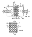
- Figs. 6a and 6b show a sixth embodiment of the invention, being a silencer with a first and a second through-flowed chamber 12 and 22, separated by a baffle wall 40. Gas flow is led into a first through-flowed chamber 12 via a first, conical diffuser 41.
- the connection between the two chambers is made of in total twenty small absorptive silencers, each providing a protrusion from the baffle wall towards a second through-flowed chamber 22.
- Each small silencer is made of a perforated pipe 42 ending in a small, conical diffuser 43.
- a residual spacing is created, constituting a terminated cavity assembly 17, which acts as a collective side-branch resonator, as illustrated by the quarter-wave pressure diagram in fig. 6a .
- the silencer casing 4 is rectangular, and not circular. This last embodiment will typically be used when bigger silencers are called for.
- the terminated cavity 17 is essentially a single cavity.
- the protrusions By moving the protrusions to be in contact with each other, or by inserting division walls, several or even many smaller cavities 17 could be created instead.
- two or more resonators for differing resonator frequencies could be created. A similar effect could be achieved by varying the lengths of differing protrusions in the embodiment shown in fig. 6 .
- Quarter-waves are most prominently set up in side-branch resonators when such resonators are pipes or function as pipes by being of a longitudinal, rather narrow shape, to create a rather distinct resonance in the longitudinal direction.
- all annular or helically extending cavities are significantly longer than the width of their annular gaps.
- the terminated cavity 17 will act as a longitudinal quarter-wave resonator.
- longitudinality can be defined as prescribing that the length L of the cavity should be at least a certain multiplication factor, such as 10 or 20, times the ratio V/S between a volume V of the cavity, and the (summed) surface(s) of the sidewall(s) of the cavity or cavities.
- Fig. 7a and 7b in contrast show a seventh embodiment with a rectangular-shaped silencer in which there are perforated conduits 44,45 of a rectangular cross-sectional shape.
- the sound absorptive material is contained within adjacent cavities on the side of which material terminated cavities 17 and 27 have been arranged.
- the cavities are providing parts of Helmholtz resonators.
- the silencers are shown to be designed with a simple outer casing. It should be understood that acoustical and spark-arresting effects similar to those demonstrated in the embodiments may also be achieved with more complicated designed silencer casings. For the sake of heat insulation, it may e.g. be preferable to design the casing as a double-wall design or multiple-wall design, possibly with heat-insulating material in spacings between the walls.
- sound absorptive material 13,23 is shown to surround perforations 7,27 of pipes in immediate vicinity of the pipes.
- protective open-structured (not preventing sound propagation) intermediate layers may separate the perforations 7,27 and the sound absorptive material 13,23.
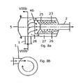
- Figs. 8a and 8b show cross-sections of an eighth embodiment of the invention.
- a per se known type of screen 47 has been fitted onto the cylinder 25 in such a way that all gas flowing through the silencer is forced to pass the screen 47.
- the screen 47 may e.g. be provided by a perforated plate or by one or more woven, metallic thread networks.
- the sizes of the openings in the screen 47 will be chosen so that they will not allow any particles greater than a certain size, for instance 0.5 mm, to pass through the screen.
- the left-hand end cap 5 of the silencer is removable (as has been indicated by flanges and bolts), which permits access to the screen for cleaning it from the outside.
- the eighth embodiment of the invention Compared to a prior art silencer providing spark-arrestor function by using a screen, the eighth embodiment of the invention has the advantage that, since a significant part of soot is retained within the terminated cavity, there will be less build-up of soot on the screen, causing less increase of pressure drop and/or permitting less frequent cleaning of the screen.
- a further aspect is that some regulations specifically demand that spark-arresting effect be attained by use of screens with a specific geometry. In such cases, the formal demand can be fulfilled without heavy build-up of soot or other particles onto the screen, by using the last shown embodiment of the invention.
- a still further aspect is that in the eighth embodiment of the invention, even if a screen should happen to break down mechanically, the silencer will retain its significant spark-arresting function; i.e. the double spark-arresting function represents a non-trivial redundancy.
- the drawing shows a preferred embodiment in which a screen has been arranged inside a silencer according to the invention. Since that screen a diameter which is much bigger than both pipes 1,2, the pressure drop across the screen will be relatively small.
- the effective area of the screen can be further increased by shaping it in various ways apart from a plane shape. Thus, for instance, the screen can be made dome-shaped, which adds the advantage of a greater mechanical stability of the screen.
Abstract
Description
- The invention relates to a silencer with an outer shell which is provided with one or more inlet conduits for leading a gas into the silencer and with one or more outlet conduits for leading the gas from the silencer. The invention also relates to such a specific silencer designed so as to provide means intended for acting as a spark-arrestor. Furthermore, the invention relates to a combustion engine provided with a silencer according to the invention.
- Reactive silencers for gas flows comprise one or more through-flowed chambers. It is known in the art of silencer design to supplement such silencers in various ways to improve a generally broad-banded noise reduction spectrum at various frequencies. Such improvement is, e.g., warranted because the un-silenced noise spectrum exhibits a peak at one or more frequencies, or because the silencer would otherwise exhibit dips in the attenuation spectrum, typically because of harmful resonance waves set up in chambers or passages of the silencer.
- A general feature of such supplementary methods relies on the use of various types of elements which are essentially not through-flowed.
- In the following, the expression "terminated cavity" will be used in the meaning of a cavity which is not through-flowed.
- One such method of supplementing a silencer consists of fitting elements containing a sound absorptive material into the silencer, such as mineral wool. Such elements will supplement silencing in a wide frequency range roughly above a certain lower limit frequency, which can be determined by analyzing standing waves set up within cavities containing the absorptive material.
- A further aspect of methods of supplementary silencing relies on the use of various types of resonators providing added noise attenuation at one or more selected frequencies. One type of such resonators is the Helmholtz resonator, which is connected to a through-flowed passage or chamber via a neck section, which is in turn connected to a terminated cavity. The peak attenuation frequency of such a Helmholtz resonator may be approximately calculated by a mass-spring analogy. The mass-spring analogy considers the mass of gas present by the neck as a stiff, concentrated mass. The flexibility of the terminated cavity and the flexibility of a cavity on the opposite side of the neck are considered as springs, each spring being connected at one end to the mass and at the other end to a steady wall. If the last-mentioned cavity is much bigger than the terminated cavity, it will act as a relatively much softer spring whose stiffness may be omitted in a rough calculation of the peak attenuation frequency.
- A third supplementary silencing element is the side-branch resonator with a closed-end pipe in which standing waves are set up to absorb sound at corresponding noise frequencies. Such a resonator will provide added noise reduction at frequencies corresponding to 0.25, 0.75, 1.25, etc. waves set up in the pipe. The frequency corresponding to 0.25 wave length will be the lowest (and usually the most prominent) one.
- It is further known to design silencers in various ways so as to act as spark arrestors, i.e. to prevent any significant amount of glowing particles (sparks) from passing the silencer, thereby reducing the risk of causing harm to human beings or causing fire or explosion in case of any inflammable substances being situated close to the exhaust.
- It is easy to fit a screen or some other particle-obstructing means into a silencer, but commonly known means of this kind generally significantly augment the pressure drop across the silencer. There is a need in the market for a silencer which can produce a significant, not necessarily a maximum, spark arresting effect with a low or a very low additional pressure drop across the silencer.
-
WO 99/50539 -
WO 01/53665 -
EP 0 127 550 discloses a silencer for a compressed air installation of the type including baffles prolongating the path of travel of the flux of air with at least one portion of the chamber of the chamber defined by a perforated wall maintaining a filling of absorbing material, the baffles being formed with orifices separating the global flux of air into elementary streams of reduced section, the orifices and the baffles being placed such that the streams collide against the wall of at least some of the adjacent baffles and/or against each other and are brought in contact with said perforated wall maintaining the filling of absorbing material, characterized in that it includes means providing for a return of said streams of air along path of travel portions which are substantially parallel but in an opposite direction with respect to the general circulation direction, the circulation in contact with the perforated wall being effected according to a total path of travel which is close to the length of the silencer. -
GB 732 936 inlet opening 2 are so arranged that the gas enters the chamber tangentially to the in-circle of the polygon. The cleaned gas leaves the vortex chamber and passes downwardly through an expansion chamber having annular baffles to discharge through an orifice 10 the effective area of which is controlled by moving a plate. The separated dust or liquid collects at the bottom of the vortex chamber and is discharged through an outlet. The walls of the vortex chamber are lined with sound-absorbing panels. - Although many silencers of known designs, even though not having been designed for such a purpose, will in fact have some spark-arresting effect, a gas flow containing particles, such as exhaust from a diesel engine, may gradually compromise a silencer in its acoustic function. One important reason for this is that perforations in the walls of such a silencer, allowing noise to be transmitted into sound absorptive material, may in the course of time become clogged, causing the desired sound absorptive effect to become gradually obstructed.
- It may be an object of the invention to provide a silencer of the reactive type with a resonator and having increased noise attenuation within confined dimensional restraints. It may also be an object of the invention to provide a silencer which is based on already applied techniques and which may be redesigned easily and cheaply.
- These objects and possible other objects are obtained by a silencer according to
claim 1 in with - an outer shell and provided with one or more pipes for leading gas flow into the silencer and with one or more outlets for leading gas from the silencer, the silencer comprising
- at least one chamber capable of being trough-flowed by gas entering the chamber and at least one perforated conduit section adjacent to which is provided sound absorptive material, and
- said sound absorptive material, in order to constitute a closed absorptive material containing cavity, except for said perforations, and said conduit section together constituting a protrusion extending from part of said outer shell, such as an end cap, or from an internal member, such as a baffle, said internal member causing separation of two through-flowed chambers of the silencer,
- said sound absorptive material being arranged adjacent to and surrounding at least one terminated cavity, or said sound absorptive material being arranged adjacent to and being surrounded by at least one terminated cavity, and where a cylindrical shell is provided between the sound absorptive material and the terminated cavity,
- said at least one terminated cavity being acoustically in communication with said at least one through-flowed chamber, and said acoustic communication being either direct or via a neck section provided between the at least one terminated cavity and the at least one through-flowed chamber, and
- said at least one terminated cavity being arranged adjacent to said sound absorptive material, thereby constituting one or more resonators acoustically communicating with said at least one through-flowed chamber.
- The invention combines, in a basically reactive type silencer, the above-mentioned absorptive type of element with either a Helmholtz resonator or with a side-branch resonator in a way which is particularly compact and cheap to manufacture. In several preferred embodiments of the invention, an annular cavity which surrounds the absorptive element is utilised as a resonator to absorb energy at one or more selected noise frequencies. By means of further, simple design features, these noise frequencies can be selected rather freely, as will be shown and explained below.
- In order for the at least one through-flowed chamber to truly act to reflect sound waves at the inlet passages to and the outlet passages from the chamber, and for the chamber to function to reduce noise efficiently from a not too high lower cut-off frequency, it is desirable that the cross-sectional area ratios of the passages in respect to the chamber cross-sectional area, and the outlet passages in respect to the chamber are not too big. It is also desirable that the chamber is of a not too small volume. These objects may be obtained by said at least one through-flowed chamber provided with one or more inlet passages for leading gas to said chamber, and being provided with one or more outlet passages for leading gas from said chamber, and where the sum ain of acoustically representative cross-sectional areas of said Inlet passages is fulfilling the condition ain < A/3C, and/or where the sum aout of acoustically representative cross-sectional areas of said outlet passages is fulfilling the condition aout < A/3C, and/or where the volume V of said chamber is fulfilling the condition

- According to one possible embodiment of the invention, said at least one terminated cavity is of a longitudinal shape along a longitudinal extension of the silencer, said cavity thereby acting as a resonator attenuating noise at frequencies corresponding to standing waves in the longitudinal direction of the cavity, the lowest of said frequencies corresponding to a standing quarter-wave. This feature presents the advantage that the silencer is tuned to specific frequencies, thus obtaining maximum noise attenuation in the number of terminated cavities. Furthermore, any one and selected wavelength of the frequency may be used for designing the length of the terminated cavity, but still making it possible to maintain the noise-attenuating properties of the remaining elements of the silencer, and not necessarily demanding a re-design of these elements because of a chosen length of the terminated cavity. Thus, the individual design features may be selected and designed rather freely and not necessarily dependent on possible mutual relationships.
- As will be demonstrated, such cavities of a longitudinal shape can be accommodated in remarkably simple and compact designs, making the silencer cheap to manufacture. Furthermore, the silencer is well-suited for augmenting the noise reduction effect of the silencer at one or more particular noise frequencies in situations where noise reduction would be insufficient if one were to rely solely on noise reduction caused by noise-reducing effects caused by a combination of the reactive/reflective effect of through-flowed chambers and the noise absorptive effect achieved by means of sound absorptive material.
- According to another possible embodiment of the invention, the terminated cavity communicates acoustically with the at least one through-flowed chamber, either directly or via a neck section provided between the at least one terminated cavity and the chamber intended for being through-flowed by gas. This feature has the general advantage of achieving additional noise-reducing effects at one or more target frequencies by simple designs. In the case of a silencer with several through-flowed chambers, it will for instance be possible to design the noise reduction characteristic of the silencer within wide limits, without resorting to complicated and costly designs.
- Depending on the specific design of the silencer, on the possible dimensional restraints and on the intended and/or demanded noise-attenuating properties, the acoustically effective length, L, of said terminated cavity is essentially equal to, smaller than, or longer than a length of said protruding sound absorptive material seen along the longitudinal extension of the silencer.
- When a terminated cavity is used as a side-branch resonator, it should be of a longitudinal shape in order to achieve a distinct resonance effect in the longitudinal direction. This may be achieved by ensuring that a mean distance between walls in radial direction, integrated over the entire longitudinal and circumferential extension of the acoustically effective length of the terminated cavity, is at the most a
ratio 1/3 of said acoustically effective length. Alternatively, the mean distance may be at the most aratio 1/5 of said acoustically effective length. As a further alternative, the mean distance may be at the most aratio 1/10 of said acoustically effective length. - When a terminated cavity is of a more complex shape, the longitudinality of the cavity can be quantified by referring to a volume V of the cavity and to summed surfaces S of side walls of the cavity. In such a case, the acoustically effective length L of said at least one terminated cavity is at least 6 times the ratio V/S between the volume of said cavity and the summed surface areas of the side walls of said terminated cavity. Alternatively, the acoustically effective length L of said at least one terminated cavity is at least 10 times the ratio V/S. As a further alternative, said acoustically effective length L of said at least one terminated cavity is at least 20 times said ratio V/S.
- The shape of said cavity may at least partly constitute a helical winding around said protruding sound absorptive material. A helical winding entails the advantage that the acoustically effective length may be longer than a length of said protruding sound absorptive material seen along the longitudinal extension of the silencer, however, without taking up as much dimensional space seen in either an axial or a radial direction in comparison with the actual acoustically effective length obtained by a helical winding.
- If the silencer is provided with at the least one neck section acoustically connecting said at least one terminated cavity with said at least one through-flowed chamber, the neck section may be designed for creating a Helmholtz-type resonator. Thereby it is possible to obtain a very pronounced additional noise reduction effect at a frequency which can be selected within a very broad range of frequencies. For instance, it becomes possible to extend the noise reduction spectrum down to very low frequencies, which may otherwise be difficult to attenuate with a silencer to be accommodated within a limit space restriction, i.e. if the silencer has to be compact.
- Furthermore, the at least one protruding sound absorptive material and the at least one essentially surrounding terminated cavity may be of a substantially circular-cylindrical configuration. This is an example as to how the invention makes it possible to accommodate three, mutually supplementing noise reduction effects in a particularly simple design. Those three effects are, noise reduction by: 1) sound reflection at cross-sectional changes at inlets and outlets of through-flowed chambers, 2) sound absorption in sound absorptive material, and 3) resonance sound absorption, either by a longish quarter-wave sound absorber, or by a Helmholtz sound absorber, all those types having been described above.
A possible embodiment of a silencer comprises at least two terminated cavities, the one terminated cavity having an acoustically effective length L1 and the at least one other terminated cavity having an acoustically effective length L2, and where said length L1 is different form said length L2. This is a demonstration of a rather simple way of designing the noise reduction characteristics of a silencer according to the invention. If more than two lengths are selected, a more sophisticated design of the noise reduction characteristics can be attained. One may target very different frequencies in some cases. In other cases, two or more targeted frequencies may differ only slightly, whereby the rather narrow-banded sound absorptive effect of a single resonator can be extended in terms of frequency range effect of the sound absorptive effect. - In order to design the outer shape of a big silencer, for instance the silencer of a big diesel engine serving the electricity needs of an island, in which the allowable length of the silencer is limited, but where it is possible design for a certain width and a certain height of a horizontally disposed silencer, at least three pieces of said protruding sound absorptive material are arranged to establish at least three parallel gas flows inside said protruding sound absorptive material, and the at least one terminated cavity is constituted by a spacing between said protruding sound absorptive material.
- This cavity may be a residual cavity found between the three or more protrusions. The cross-sectional shape of this residual cavity may appear complicated, but since it is a residual cavity, it can be accommodated by a very simple design, as will be demonstrated below. If the residual cavity is used as a quarter-wave resonator, it should be of a rather longish shape, which can be obtained simply by designing the protrusions to be of a certain minimum length and by accommodating the protrusions close to each other, so that the mean transverse direction between the protrusions becomes rather small.
- If at least three protruding pieces of sound absorptive material are provided, more of said cavities are formed by sub-dividing said spacing, possibly by sub-dividing said spacing by establishing insertions of one or more walls between said protruding sound absorptive material. The sub-division of the spacing may be established by inserting one or more walls between the protruding sound absorptive material and another member of the silencer, e.g. the outer shell of the silencer. The sub-division can be used for having different lengths of different quarter-wave resonators. Walls for subdivision may nevertheless be necessary to provide sufficient stiffness to the assembly of protrusions.
- At least one resonator of the silencer is constituted by at least one terminated cavity at least partly surrounding the protruding sound absorptive material, tuned so as to target a peak frequency of an un-attenuated noise spectrum to be attenuated by the silencer.
- According to an aspect of the invention, the silencer is designed so as to provide means intended for acting as a spark-arrestor, said means comprising the at least one terminated cavity capable of collecting particles separated from the gas flow as the spark-arresting function. Preferably, at least one of the following flow motions; radial outward flow motion, radial inward flow motion and swirling flow motion, is enforced upon the gas flow passing through the silencer, thereby promoting particles contained in the gas flow to be collected in the at least one terminated cavity designed as a spark-arrestor.
- Spark-arresting function is commonly called for in exhaust systems, especially exhaust systems of diesel engines, where the exhaust will contain particles of various sizes. Such particles will tend to clog any perforations in communication with the sound absorptive material, especially in cases where the perforations are not continuously being swept by a gas flow. Such clogging can gradually compromise the sound absorptive function of the sound absorptive material. Larger particles may be glowing for a long time after having been exhausted form the engine as such, and if such glowing particles are transmitted to the environment, they may cause harm such as fires or even explosions. Thus, according to another aspect, the invention also relates to a combustion engine provided with a silencer according to the invention, said combustion engine preferably being a diesel engine.
- It will be demonstrated below how the invention makes it possible to attain a significant spark-arresting effect without resorting to design elements that would cause a significant increase of pressure drop across the silencer.
- It will also be demonstrated how the invention can be adapted to contain instead one or more screens inside a silencer in a way that provides an enhanced spark arresting function in such a way that there will be less accumulation of soot or other particles onto such screens, compared to prior art silencers providing spark arresting by means of screens.
- In the following, the invention will be described in more detail by reference to the figures where:
-
Fig. 1 shows a longitudinal cross-section of a first embodiment of the invention, -
Fig. 2 shows a longitudinal cross-section of a second embodiment of the invention, -
Fig. 3a shows a longitudinal cross-section of a third embodiment of the invention, -
Fig. 3b shows a transverse cross-section of the third embodiment of the invention, -
Fig. 4 shows a longitudinal cross-section of a fourth embodiment of the invention, -
Fig. 5 shows a longitudinal cross-section of a fifth embodiment of the invention, -
Fig. 6a shows a longitudinal cross-section of a sixth embodiment of the invention, -
Fig. 6b shows a transverse cross-section of the sixth embodiment of the invention, -
Fig. 7a and 7b show cross-sections of a seventh embodiment of the invention and -
Figs. 8a and 8b show cross-sections of an eighth embodiment of the invention. -
Fig. 1 shows a longitudinal cross-section of a first, essentially circular-cylindrical embodiment of a silencer according to the invention. The silencer has at least onecasing 3. Afirst pipe 1 is leading a gas flow into the silencer, and asecond pipe 2 is leading gas from the silencer. Thecasing 3 is composed of acylinder 4 fitted with aconical end cap 5,6 at each end of the silencer. The end caps 5,6 may have other shapes such as plane or spherical, and the end caps may also have individually different shapes. The first pipe extends into the silencer at least partly along aperforated pipe section 7 leading up to aradial diffuser 8, composed of two circular-symmetrical baffles 9,10 held together by radially extendingribs 11. In the shown cross-section, twosuch ribs 11 are shown to fall within the sectional plane. Typically, further ribs will be provided, e.g. in total eight ribs positioned with intersecting angles of 45 degrees. From thediffuser 8, gas continues to flow inside a through-flowedchamber 12. - From a
position 14 in the immediate vicinity of theend cap 5, alternatively at a position more or less remote from theend cap 5, theperforated pipe section 7 is surrounded by soundabsorptive material 13 contained between the pipe and acylindrical shell 15. The whole assembly ofpipe section 7, soundabsorptive material 13,cylinder 4 andradial diffuser 8 all together provide aprotrusion 16 from theend cap 5 at thefirst pipe 1 into the silencer interior. Theprotrusion 16 may also be constituted only by at least thepipe section 7 and the soundabsorptive material 13, thus omitting either thecylinder 4 or theradial diffuser 8, or omitting both thecylinder 4 and theradial diffuser 8. Theprotrusion 16 is surrounded by an annular spacing, providing a terminatedcavity 17 between thecylindrical shell 15 and theouter casing 3 of the silencer. - The terminated
cavity 17 acts as a side-branch resonator acoustically communicating with the through-flowedchamber 12 through anopening 18. Inside the resonator, during operation of the silencer, standing waves are set up, said standing waves having the effect of absorbing sound energy from the through-flowedchamber 12 at corresponding frequencies. The lowest of these frequencies is the one whose quarter-wave pressure amplitude p variation from the closed end of the terminatedcavity 17 to theopening 18 is shown adjacent to the silencer. In the embodiment shown, the resonator length L1 is essentially the same as the length P1 of theprotrusion 16. - The
second pipe 2 extends backwards into the silencer by aperforated pipe section 27 which is surrounded by soundabsorptive material 23 extending from a position 24 in the immediate vicinity of the end cap 6, alternatively at a position more or less remote from the end cap 6. The soundabsorptive material 23 is surrounded by acylindrical shell 25. Smooth gas flow from the through-flowedchamber 12 into thesecond pipe 2 is provided for by means of aconical baffle 19, which together with thecylindrical shell 25 acoustically closes off the soundabsorptive material 23 against the through-flowedchamber 12. Between thecylindrical shell 25 and thecylindrical silencer casing 4, a terminatedcavity 27 is formed, which is an annularly shaped side-branch, communicating acoustically with the through-flowedchamber 12 via anopening 28. - The
perforated pipe section 27, the soundabsorptive material 23, thecylindrical shell 25, and aconical baffle 19 together constitute abackward protrusion 26 into the silencer. The length L2 of the terminatedcavity 27 has been made shorter than the length P2 of thebackward protrusion 26 by insertion of anannular baffle 29 between thecylindrical shell 25 and thecylindrical casing 4 of the silencer. - This feature has the effect of shortening the length of the quarter-wave, as can be seen from the small diagram of pressure amplitude, shown adjacent to the silencer. Corresponding to the shortened quarter-wave is a higher peak frequency of sound absorption associated with the resonator, for which it could be desirable to target a certain peak in the un-attenuated noise frequency spectrum, or a dip in the attenuation spectrum of a corresponding silencer without the
annular baffle 29. - Summing up,
fig. 1 is an example of a silencer comprising two terminatedcavities cavity 17 could be increased by inserting an element like theannular baffle 29 in this cavity as well. -
Fig. 2 shows a second embodiment of the invention in which the acoustically effective length L of a terminatedcavity 17 has been made significantly longer than a length P of aprotrusion 16 into the silencer. This has been achieved by fitting a helically extending,annular wall 30 inside the terminatedcavity 17. This feature creates a significant lowering of standing-wave frequencies, starting with the quarter-wave. -
Figs. 3a and 3b show a third embodiment of the invention. In addition to noise reduction, this silencer has been designed to act as a spark-arrestor in whichparticles 31 are collected at the bottom of an annular, terminatedcavity 17. The particles accumulating at the bottom of the terminatedcavity 17 can be sucked out of thecavity 17 via asuction pipe 32. Aradial diffuser 8 has been fitted with bendingribs 11 as can be seen fromfig. 3b . These bendingribs 11 will cause the radial flow between the baffles 9 and 10 to bend inside thediffuser 8 to leave thediffuser 8 with a tangential component, imparting a centrifugal force on the gas and on particles contained in the gas. - Thereby, especially larger particles, e.g. those whose glow is potentially the most harmful to the environment if not retained, are forced towards the inner side of the silencer casing, from which the particles, due to gravity, will fall downwards to be collected at the bottom of the cavity as indicated by dotted arrows in
fig. 3a . The baffle 9 is shown to be tapered at its periphery, facilitating a 180 degree turning of flow direction of particles. Full arrows show paths of gas flow and of small particles following the gas flow. Aconical baffle 33 extending inwardly into the through-flowedchamber 12 assists in separating bigger particles from the gas flow through the silencer, at the same time being shaped so as not to create too great a flow-restriction on gas flow. - It is to be noted that the
radial diffuser 8, as indicated infig. 3a , has been designed to cause the gas to flow in an outward, perpendicular direction to the longitudinal axis of thepipe section 1 and the to the whole silencer. This differs from flow conditions in the (also radial) diffuser shown infig. 1 , in which the radial flow between baffles 9 and 10 has a small axial component. I.e. in the embodiment shown infig. 1 the change of direction of flow from the incoming axial direction in thefirst pipe 1 is somewhat smaller. A design as shown infig. 1 tends to improve the degree of pressure recovery in the diffuser. The 90 degree change of flow direction in thediffuser 8 shown infig. 3a instead represents some sacrifice of pressure recovery for the benefit of more efficient particle separation. - For a given distance between baffles 9 and 10 in the embodiment shown in
fig. 3a , the tangential component of flow exiting thediffuser 8 increases the dynamic pressure of flow leaving the diffuser. Since this dynamic pressure is virtually dissipated inside the through-flowedchamber 12, the tangential flow component tends to decrease the pressure recovery in the diffuser. This could be compensated for by increasing the distance between the baffles, but would simultaneously cause a less efficient separation of particles. Thus, there is a trade-off between pressure recovery and efficiency of particle separation. When a maximum of particle separation is the objective, the diffuser may be designed with such a big absolute velocity of flow leaving the diffuser that there is a positive pressure drop across the diffuser 8 (no net pressure recovery). -
Fig. 4 shows a fourth embodiment of the invention, featuring both another spark-arresting arrangement and a not previously shown feature of a terminated cavity acting as a side-branch resonator. - In
fig. 3a , the terminatedcavity 17 in which particles are retained surrounds the protrusion comprising thediffuser 8 causing flow to change direction. By contrast, infig. 4 , where there are first and second terminatedcavities second cavity 27 which does not surround the firstprotrusion comprising diffuser 8. Such an arrangement facilitates an overall design for low pressure drop across the silencer, still causing a particle separation effect, since the radial diffuser forces the flow to bend twice. Bigger particles, due to their inertia, will tend to be caught by thesecond cavity 27, in which they are collected at the bottom, noticing that infig. 4 the silencer has been arranged horizontally. Two dotted lines indicate flow paths of bigger particles. Some particles enter the upper part of thesecond cavity 27 and thereafter follow a course of turning around the symmetry axis of the annular cavity. The corresponding curved, dotted line is a projection of the three-dimensional particle flow path in the longitudinal section shown on the drawing. - It should be noted that, although as mentioned, the flow through the silencer has been forced to follow rather abrupt changes of flow direction, there will not be any big pressure drop across the silencer. One important reason for this can be found in the use of the radial diffuser, which can be designed for a negative pressure (i.e. a pressure recovery) across this particular design element. Also, collecting the particles in the
second cavity 27 is associated with a minimal pressure loss, since the flow, when forced inwardly from the outer shell has a rather low flow velocity. - The second feature illustrated in
fig. 4 is a continuous, angular variation of the length L of the first terminatedcavity 17 between a minimum length Lmin and a maximum length Lmax. A helically extendingannular wall 30 extending 360 degrees round causes this angular variation of L. A plane, longitudinally extendingmember 34 positioned in the upper-left part of the annular spacing betweencylinder 15 and thecylindrical silencer casing 3 connects the two ends of theannular wall 30 and closes off the resonator towards the residual, annular spacing to the left of theannular wall 30. - This variation of length L increases the band-width of attenuation, caused by the side-branch, at the expense of a lowered peak attenuation. Such increase of band-width may be desirable if the frequency in which added attenuation is needed is not known exactly and/or if it varies, e.g. due to varying speed of an engine.
-
Fig. 5 shows a fifth embodiment according to the invention. Here, a Helmholtz resonator surrounds aprotrusion 16 extending into the interior of the silencer, and comprising soundabsorptive material 13 as in all the previously shown embodiments. The Helmholtz resonator consists of a resonator volume provided by a terminatedannular cavity 17 and a similarannular neck section 35, which communicates acoustically, both with the through-flowedchamber 12 at theopening 18A and with the terminatedcavity 17 at theopening 18B. Theneck section 35 is created by adding ashort cylinder 36 whose diameter is larger than that of thecylinder 15. As previously mentioned, the Helmholtz resonator allows for frequency-targeted noise reduction within a particularly broad range of frequencies to be selected as target frequency. -
Figs. 6a and 6b show a sixth embodiment of the invention, being a silencer with a first and a second through-flowedchamber baffle wall 40. Gas flow is led into a first through-flowedchamber 12 via a first,conical diffuser 41. The connection between the two chambers is made of in total twenty small absorptive silencers, each providing a protrusion from the baffle wall towards a second through-flowedchamber 22. Each small silencer is made of aperforated pipe 42 ending in a small,conical diffuser 43. Between the protrusions and the inner side walls of the silencer casing 4 a residual spacing is created, constituting a terminatedcavity assembly 17, which acts as a collective side-branch resonator, as illustrated by the quarter-wave pressure diagram infig. 6a . Unlike the previous embodiments, thesilencer casing 4 is rectangular, and not circular. This last embodiment will typically be used when bigger silencers are called for. - In
fig. 6 , since the protrusions are positioned slightly apart, the terminatedcavity 17 is essentially a single cavity. By moving the protrusions to be in contact with each other, or by inserting division walls, several or even manysmaller cavities 17 could be created instead. Further, by insertion of walls analogous toannular baffle 29 of the embodiments shown infigs. 1 and3 , two or more resonators for differing resonator frequencies could be created. A similar effect could be achieved by varying the lengths of differing protrusions in the embodiment shown infig. 6 . - Quarter-waves are most prominently set up in side-branch resonators when such resonators are pipes or function as pipes by being of a longitudinal, rather narrow shape, to create a rather distinct resonance in the longitudinal direction. Thus, in the embodiments shown in
figs. 1-4 , all annular or helically extending cavities are significantly longer than the width of their annular gaps. Also, infig. 6 , the terminatedcavity 17 will act as a longitudinal quarter-wave resonator. In cases like the last-mentioned, in which the cavity is of a complex shape, longitudinality can be defined as prescribing that the length L of the cavity should be at least a certain multiplication factor, such as 10 or 20, times the ratio V/S between a volume V of the cavity, and the (summed) surface(s) of the sidewall(s) of the cavity or cavities. - In all previously shown embodiments, the perforated pipes and the protruding sound absorptive material have been shown to be circular-cylindrical, and the sound absorptive material as well as the terminated cavities have been shown to surround the perforated pipes.
Fig. 7a and 7b in contrast show a seventh embodiment with a rectangular-shaped silencer in which there areperforated conduits cavities neck sections - In all the embodiments shown, the silencers are shown to be designed with a simple outer casing. It should be understood that acoustical and spark-arresting effects similar to those demonstrated in the embodiments may also be achieved with more complicated designed silencer casings. For the sake of heat insulation, it may e.g. be preferable to design the casing as a double-wall design or multiple-wall design, possibly with heat-insulating material in spacings between the walls.
- Further, in all the embodiments, sound
absorptive material perforations perforations absorptive material -
Figs. 8a and 8b show cross-sections of an eighth embodiment of the invention. Here, a per se known type of screen 47 has been fitted onto thecylinder 25 in such a way that all gas flowing through the silencer is forced to pass the screen 47. The screen 47 may e.g. be provided by a perforated plate or by one or more woven, metallic thread networks. The sizes of the openings in the screen 47 will be chosen so that they will not allow any particles greater than a certain size, for instance 0.5 mm, to pass through the screen. - Flow enters the silencer tangentially to the
cylindrical shell 4 viainlet pipe 1 so that a rotating flow pattern is set up inside the chamber of the silencer to the left of theassembly 26 extending backwards from silencer outlet into the interior of the silencer. As a result of centrifugal forces acting on particles, this rotational flow will cause bigger particles to move towards the inner surface of the shell, so that such bigger particles, following paths indicated by to dotted curves, will enter the terminatedcavity 27 via theannular opening 28, to accumulate within this cavity. - Smaller particles will be subject to less strong centrifugal forces and will therefore be more prone to follow the gas stream which will converge towards the
inflow 2 via the screen. Any particle that is sufficiently small not to be captured in the terminated cavity, but which is bigger than the size of the openings of the screen, will be retained on the upstream side of the screen. The left-hand end cap 5 of the silencer is removable (as has been indicated by flanges and bolts), which permits access to the screen for cleaning it from the outside. - Compared to a prior art silencer providing spark-arrestor function by using a screen, the eighth embodiment of the invention has the advantage that, since a significant part of soot is retained within the terminated cavity, there will be less build-up of soot on the screen, causing less increase of pressure drop and/or permitting less frequent cleaning of the screen.
- Although all the previous embodiments of the invention shown in
figs. 1 to 7 , when properly designed, may in many cases provide a satisfactory spark arresting function, insertion of a screen can be motivated to improve the spark-arresting function in various circumstances. Conversely, the eighth embodiment of the invention can be preferable to other types of silencers comprising a screen, due to better acoustical performance, as well as further considerations. The screen shown infig. 8a may nonetheless be provided in any of the embodiments shown infigs. 1 to 7 . - By using small openings of the screen even very small particles can be retained. When spark-arresting relies on a screen only, the designer will tend to not choose too small openings, since that could result in rather rapid build-up of soot on the screen. When the silencer is designed to be relatively small, particles following the gas flow will reside inside the silencer only during a short time interval. This may call for use of a screen with small openings. Another example in which adding a screen can be motivated is when an engine sometimes runs at low rotational speed, in which case gas velocities within the silencer will be small, causing a decrease of centrifugal forces on particles.
- A further aspect is that some regulations specifically demand that spark-arresting effect be attained by use of screens with a specific geometry. In such cases, the formal demand can be fulfilled without heavy build-up of soot or other particles onto the screen, by using the last shown embodiment of the invention. A still further aspect is that in the eighth embodiment of the invention, even if a screen should happen to break down mechanically, the silencer will retain its significant spark-arresting function; i.e. the double spark-arresting function represents a non-trivial redundancy.
- The drawing shows a preferred embodiment in which a screen has been arranged inside a silencer according to the invention. Since that screen a diameter which is much bigger than both
pipes
Claims (40)
- A silencer with- an outer shell (4) and provided with one or more conduits (1) for leading gas flow into the silencer and with one or more outlets (2) for leading gas from the silencer, the silencer comprising- at least one chamber (12) capable of being trough-flowed by gas entering the chamber (12) and at least one perforated conduit section (1,2) being acoustically in communication with sound absorptive material (13,23) arranged adjacent to the perforated conduit section (1,2),- said sound absorptive material (13,23) and conduit section (1,2) together constituting a protrusion extending from part of said outer shell (4), for example from an end cap constituting part of the shell of the silencer, or from an internal member, for example a baffle (9,10) separating at least two through-flowed chambers (12) of the silencer, said silencer characterised in- said sound absorptive material (13,23) being arranged adjacent to and surrounding at least one terminated cavity (17,27), or said sound absorptive material (13,23) being arranged adjacent to and being surrounded by at least one terminated cavity (17,27), and where a cylindrical shell (15,25) is provided between the sound absorptive material (13,23) and the at least one terminated cavity (17,27),- said at least one terminated cavity (17,27) being acoustically in communication with said at least one through-flowed chamber (12), and said acoustic communication being either direct or via a neck section (35,45) provided between the at least one terminated cavity (17,27) and the at least one through-flowed chamber (12), and- said at least one terminated cavity (17,27) being arranged adjacent to said sound absorptive material (13,23), thereby constituting one or more resonators acoustically communicating with said at least one through-flowed chamber (12).
- A silencer according to claim 1, wherein said sound absorptive material (13,23) is contained within a casing (15,25) surrounding said conduit section (1,2), and where said casing (15,25) constitutes a cavity containing sound absorptive material, said casing (15,25) surrounding said conduit section (1,2).
- A silencer according to claim 2, wherein said at least one terminated cavity (17,27) surrounds said cavity (15,25) containing sound absorptive material.
- A silencer according to any of the preceding claims, wherein said at least one through-flowed chamber (12) is provided with one or more inlet passages (1) for leading gas to said chamber, and is provided with one or more outlet passages (2) for leading gas from said chamber, and where the sum ain of acoustically representative cross-sectional areas of said inlet passages is fulfilling the condition ain<A/(3C), A being an acoustically representative cross-sectional area of said chamber (12) and C being a constant taking the value of C being at least 1.
- A silencer according to any of the preceding claims, wherein said at least one through-flowed chamber (12) is provided with one or more inlet passages for leading gas to said chamber, and is provided with one or more outlet passages (2) for leading gas from said chamber, and where the sum aout of acoustically representative cross-sectional areas of said outlet passages is fulfilling the condition aout<A/(3C), A being an acoustically representative cross-sectional area of said chamber (12) and C being a constant taking the value of C being at least 1.
- A silencer according to any of the preceding claims, wherein said at least one through-flowed chamber (12) is provided with one or more inlet passages (1) for leading gas to said chamber, and is provided with one or more outlet passages (2) for leading gas from said chamber, where the sum ain of acoustically representative cross-sectional areas of said inlet passages, and where the sum aout of acoustically representative cross-sectional areas of said outlet passages, and where the volume V of said chamber is fulfilling the condition

- A silencer according to any of claims 4-6, wherein said constant C takes the value of C being 2.
- A silencer according to any of claims 4-6, wherein said constant C takes the value of C being 3.
- A silencer according to any of the preceding claims, wherein said at least one terminated cavity (17,27) is of a longitudinal shape along a longitudinal extension of said perforated conduit, said cavity thereby acting as a resonator attenuating noise at frequencies corresponding to standing waves in the longitudinal direction of the silencer, the lowest of said frequencies corresponding to a standing quarter-wave, an acoustically effective length, L, of said cavity being essentially equal to, or smaller than, or longer than a length of said protruding sound absorptive material seen along the longitudinal extension of the silencer.
- A silencer according to any of the preceding claims, wherein the acoustically effective length, L, of said at least one terminated cavity (17,27) is at least 6 times the ratio V/S between a volume, V, of said casing (4), and summed surface areas, S, of side walls of said terminated cavity (17,27).
- A silencer according to claim 10, wherein the acoustically effective length, L, of said at least one terminated cavity (17,27) is at least 10 times the ratio V/S between the volume, V, of said casing (4), and the summed surface areas, S, of side walls of said terminated cavity (17,27).
- A silencer according to claim 11, wherein said acoustically effective length, L, of said at least one terminated cavity (17,27) is at least 20 times said ratio V/S between the volume, V, of said casing, and the summed surface areas, S, of side walls of said terminated cavity (17,27).
- A silencer according to any of the preceding claims, wherein said at least one terminated cavity (17,27) is of annular shape.
- A silencer according to claim 13, wherein the mean distance, a, between walls in radial direction, integrated over the entire longitudinal and circumferential extension of the acoustically effective length of the terminated cavity (17,27) is at the most a ratio 1/3 of said acoustically effective length, L.
- A silencer according to claim 14, wherein the mean distance, a, is at the most a ratio 1/5 of said acoustically effective length, L.
- A silencer according to claim 15, wherein the mean distance, a, is at the most a ratio 1/10 of said acoustically effective length, L.
- A silencer according to any of claims 9-16, wherein said acoustically effective length, L, of said terminated cavity (17,27) is essentially equal to a length of said protruding sound absorptive material seen along the longitudinal extension of the silencer.
- A silencer according to any of claims 9-16, wherein said acoustically effective length, L, of said terminated cavity (17,27) is smaller than a length of said protruding sound absorptive material seen along the longitudinal extension of the silencer.
- A silencer according to any of claims 9-16, wherein said acoustically effective length, L, of said terminated cavity (17,27) is longer than a length of said protruding sound absorptive material seen along the longitudinal extension of the silencer.
- A silencer according to claim 19, wherein the shape of said at least one terminated cavity (17,27) at least partly constitutes a helical winding around said protrusion.
- A silencer according to any of claims 9-20, wherein said acoustically effective length, L,, depending on between which parts of the silencer said length is measured, varies between a minimum, Lmin, and a maximum, Lmax, of said length L, and where said length L is being interpreted as a mean value between Lmin and Lmax.
- A silencer according to claim 1, wherein the at least one neck passage acoustically connecting said at least one terminated cavity (17,27) with said at least one through-flowed chamber (12) is designed for creating a Helmholtz-type resonator.
- A silencer according to any of the preceding claims, wherein said casing constituting a cavity containing sound absorptive material is of a substantially circular-cylindrical configuration.
- A silencer according to any of the preceding claims, wherein said at least one piece of protruding sound absorptive material and said at least one essentially surrounding terminated cavity (17,27) is of substantially circular-cylindrical configuration.
- A silencer according to any of the preceding claims, wherein said perforated conduit is of a substantially circular-cylindrical cross-sectional shape and is capable of leading gas into the at least one through-flowed chamber (12) via a radial diffuser.
- A silencer according to any of the preceding claims, wherein the entire silencer, except for connections to conduits leading gas to and from the silencer, is of substantially circular-cylindrical configuration.
- A silencer according to any of the preceding claims, wherein said silencer comprises at least two terminated cavities (17,27), the one terminated cavity having an acoustically effective length L1 and the at least one other terminated cavity having an acoustically effective length L2, and where said length L1 is different from said length L2.
- A silencer according to any of the preceding claims, wherein at least three pieces of said protruding sound absorptive material are arranged to establish at least three parallel gas flows inside said protruding sound absorptive material, and wherein said at least one terminated cavity (17,27) is constituted by a spacing between said protruding pieces of sound absorptive material.
- A silencer according to claim 28, wherein more of said terminated cavities (17,27) are formed by sub-dividing said spacing.
- A silencer according to claim 29, wherein sub-division of said spacing is established by inserting one or more walls between said protruding sound absorptive material.
- A silencer according to claim 29, wherein sub-division of said spacing is established by inserting one or more walls between said protruding sound absorptive material and another member of the silencer.
- A silencer according to any of the preceding claims, wherein at least one said resonator, constituted by at least one terminated cavity (17,27) at least partly surrounding protruding sound absorptive material, is tuned so as to target one or more peak frequencies of an un-attenuated noise spectrum to be attenuated by said silencer.
- A silencer according to any of the preceding claims, wherein said silencer is designed so as to provide means for spark-arresting, said means comprising said at least one terminated cavity (17,27) capable of collecting particles separated from the gas flow as the spark-arresting function.
- A silencer according to claim 33, wherein said spark-arrestor is shaped as a radial diffuser.
- A silencer according to claim 34, wherein said radial diffuser is provided with ribs capable of guiding flow towards the periphery of said diffuser, said ribs being of such a shape that gas flow leaves said diffuser with a tangential flow direction component, thus acting as a swirl generator.
- A silencer according to claim 33, wherein at least one of the following flow motions: radial outward flow motion, radial inward flow motion and swirling flow motion is enforced upon the gas flow passing through the silencer, thereby promoting particles contained in the gas flow to be collected in said at least one terminated cavity (17,27).
- A silencer according to any of the preceding claims, wherein gas flow, when passing through said silencer, passes at least one screen (47) provided with openings, the size of said openings being selected so that any particles that are of a size greater than the size of the openings will be retained, either on the upstream side of a said screen or otherwise within the silencer.
- A silencer according to claim 37, wherein at least one of said at least one screen are provided onto a number of protrusions, such that gas leaving one or more chambers of the silencer will pass through said at least one screen prior to entering said number of protrusions.
- Use of a silencer according to any of the preceding claims, characterised in said use being for silencing acoustical emission from exhaust gases from a combustion engine.
- Use according to claim 39, characterised in said use being for silencing acoustical emission from exhaust gases from a diesel engine.
Applications Claiming Priority (2)
| Application Number | Priority Date | Filing Date | Title |
|---|---|---|---|
| DKPA200400851 | 2004-05-28 | ||
| PCT/DK2005/000353 WO2005116409A1 (en) | 2004-05-28 | 2005-05-27 | Combination silencer |
Publications (2)
| Publication Number | Publication Date |
|---|---|
| EP1781907A1 EP1781907A1 (en) | 2007-05-09 |
| EP1781907B1 true EP1781907B1 (en) | 2009-07-29 |
Family
ID=34968408
Family Applications (1)
| Application Number | Title | Priority Date | Filing Date |
|---|---|---|---|
| EP05744475A Not-in-force EP1781907B1 (en) | 2004-05-28 | 2005-05-27 | Combination silencer |
Country Status (5)
| Country | Link |
|---|---|
| US (1) | US20080023265A1 (en) |
| EP (1) | EP1781907B1 (en) |
| AT (1) | ATE438023T1 (en) |
| DE (1) | DE602005015724D1 (en) |
| WO (1) | WO2005116409A1 (en) |
Families Citing this family (13)
| Publication number | Priority date | Publication date | Assignee | Title |
|---|---|---|---|---|
| JP2009133288A (en) * | 2007-11-30 | 2009-06-18 | Yamaha Motor Co Ltd | Exhaust device for straddle-type vehicle and straddle-type vehicle |
| JP2009287548A (en) * | 2008-04-30 | 2009-12-10 | Yamaha Motor Co Ltd | Exhaust device for straddle-type vehicle and straddle-type vehicle |
| JP5866751B2 (en) * | 2009-11-30 | 2016-02-17 | ヤマハ株式会社 | Acoustic resonator and acoustic chamber |
| KR101774076B1 (en) * | 2010-05-18 | 2017-09-01 | 그라코 미네소타 인크. | Low ice pneumatic motor exhaust muffler |
| US8708779B2 (en) * | 2011-02-04 | 2014-04-29 | Phuong Taylor Nguyen | Air blast blowdown silencer system for blast pot |
| US9121319B2 (en) | 2012-10-16 | 2015-09-01 | Universal Acoustic & Emission Technologies | Low pressure drop, high efficiency spark or particulate arresting devices and methods of use |
| US9874125B2 (en) | 2013-10-10 | 2018-01-23 | Miratech Group, Llc | Quadruple-tuned silencer apparatus and method for attenuating sound from an engine exhaust |
| GB201709986D0 (en) * | 2017-06-22 | 2017-08-09 | Univ Manchester | Apparatus for modifying acoustic transmission |
| CN109325393B (en) | 2017-08-01 | 2022-12-09 | 苹果公司 | Face detection, pose estimation, and estimation of distance to camera using a single network |
| CN108665886A (en) * | 2018-05-23 | 2018-10-16 | 南京邮电大学 | A kind of ultra-thin perforation plate absorbing body of rigidity with resonance sound-absorbing structure |
| US10769414B2 (en) | 2018-06-03 | 2020-09-08 | Apple Inc. | Robust face detection |
| US20210231035A1 (en) * | 2020-01-24 | 2021-07-29 | K&N Engineering, Inc. | Sound attenuating engine exhaust system |
| CN114991913B (en) * | 2022-06-14 | 2023-05-30 | 广州三业科技有限公司 | Multistage rotational flow spark extinguisher with noise elimination function |
Family Cites Families (28)
| Publication number | Priority date | Publication date | Assignee | Title |
|---|---|---|---|---|
| US2329101A (en) * | 1940-06-08 | 1943-09-07 | Burgess Battery Co | Apparatus for silencing pulsating gas streams and separating particles therefrom |
| GB732936A (en) * | 1953-04-30 | 1955-06-29 | Drysdale & Co Ltd | Combined silencer and liquid or dust separator |
| US2937707A (en) * | 1955-12-06 | 1960-05-24 | Ernst Josef | Muffler for silencing gases |
| US3154388A (en) * | 1962-09-07 | 1964-10-27 | Universal Oil Prod Co | Converter-muffler |
| US3235003A (en) * | 1963-06-04 | 1966-02-15 | Cloyd D Smith | Spiral flow baffle system |
| US3897853A (en) * | 1971-11-24 | 1975-08-05 | Silentor As | Silencer |
| US4074975A (en) * | 1973-05-07 | 1978-02-21 | Nissan Motor Company, Limited | Combination exhaust-gas cleaner and muffler for an automobile engine |
| US4108276A (en) * | 1976-09-20 | 1978-08-22 | Nelson Industries, Inc. | Vent silencer |
| US4192402A (en) * | 1977-05-27 | 1980-03-11 | Honda Giken Kogyo Kabushiki Kaisha | Muffler for internal combustion engines |
| US4318720A (en) * | 1979-07-19 | 1982-03-09 | Hoggatt Donald L | Exhaust filter muffler |
| EP0161692B1 (en) * | 1981-11-05 | 1988-02-03 | Mitsubishi Denki Kabushiki Kaisha | Sound-absorbing device for use as muffler for exhaust gas from an internal combustion engine |
| FR2546970B1 (en) * | 1983-05-31 | 1987-09-25 | Mareau Betty | SILENCER FOR COMPRESSED AIR INSTALLATION |
| US4712643A (en) * | 1987-02-17 | 1987-12-15 | Nelson Industries, Inc. | Particulate trap exhaust muffler |
| US4841728A (en) * | 1987-07-10 | 1989-06-27 | Jyh-Jian Jean | Straight through type muffler for generating the exhaust flow from an internal combustion engine |
| US5248859A (en) * | 1991-03-25 | 1993-09-28 | Alexander Borla | Collector/muffler/catalytic converter exhaust systems for evacuating internal combustion engine cylinders |
| US5396764A (en) * | 1994-02-14 | 1995-03-14 | Ford Motor Company | Spark ignition engine exhaust system |
| JP3656917B2 (en) * | 1994-06-11 | 2005-06-08 | 本田技研工業株式会社 | Spark arrester device for vehicle exhaust system |
| WO1996036796A1 (en) * | 1995-05-19 | 1996-11-21 | Silentor A/S | A silencer with incorporated catalyst |
| FR2736966B1 (en) * | 1995-07-17 | 1997-10-17 | Ferri Alain | EXHAUST MUFFLER FOR EXPLOSION ENGINES, FOR AIRCRAFT |
| JPH09144986A (en) * | 1995-11-27 | 1997-06-03 | Nissan Motor Co Ltd | Noise absorbing duct structure |
| JP2001501269A (en) * | 1996-09-30 | 2001-01-30 | シレントーア ノトックス アクティーゼルスカブ | Gas flow silencer |
| US5859393A (en) * | 1997-05-19 | 1999-01-12 | Nelson Industries, Inc. | Reduced cost vent silencer |
| CA2373774A1 (en) * | 1998-03-30 | 1999-10-07 | Silentor Holding A/S | A silencer and a method of operating a vehicle |
| JP2002089232A (en) * | 2000-01-21 | 2002-03-27 | Inter Db:Kk | Silencer for exhaust system |
| WO2001071169A1 (en) * | 2000-03-21 | 2001-09-27 | Silentor Holding A/S | A silencer containing one or more porous bodies |
| JP3493344B2 (en) * | 2001-01-23 | 2004-02-03 | 川崎重工業株式会社 | Exhaust system for riding type rough terrain vehicle |
| US6968923B2 (en) * | 2003-07-30 | 2005-11-29 | Control Components, Inc. | Reduced noise valve stack connection |
| CA2498409C (en) * | 2004-03-03 | 2011-05-17 | Sylvain Lalonde | Compact silencer |
-
2005
- 2005-05-27 US US11/597,750 patent/US20080023265A1/en not_active Abandoned
- 2005-05-27 EP EP05744475A patent/EP1781907B1/en not_active Not-in-force
- 2005-05-27 DE DE602005015724T patent/DE602005015724D1/en not_active Expired - Fee Related
- 2005-05-27 WO PCT/DK2005/000353 patent/WO2005116409A1/en active Application Filing
- 2005-05-27 AT AT05744475T patent/ATE438023T1/en not_active IP Right Cessation
Also Published As
| Publication number | Publication date |
|---|---|
| WO2005116409A1 (en) | 2005-12-08 |
| DE602005015724D1 (en) | 2009-09-10 |
| WO2005116409B1 (en) | 2006-01-05 |
| US20080023265A1 (en) | 2008-01-31 |
| EP1781907A1 (en) | 2007-05-09 |
| ATE438023T1 (en) | 2009-08-15 |
Similar Documents
| Publication | Publication Date | Title |
|---|---|---|
| EP1781907B1 (en) | Combination silencer | |
| US6213251B1 (en) | Self-tuning exhaust muffler | |
| US6415887B1 (en) | Refractive wave muffler | |
| US4368799A (en) | Straight-through flow muffler | |
| US6571910B2 (en) | Method and apparatus for improved noise attenuation in a dissipative internal combustion engine exhaust muffler | |
| KR100306339B1 (en) | Muffler for internal combustion engine | |
| EP1403476B1 (en) | Gas flow silencer | |
| US20040040782A1 (en) | Silencer containing one or more porous bodies | |
| US9103263B2 (en) | Method of and apparatus for exhausting internal combustion engines | |
| US5403557A (en) | Emission control apparatus for diesel engine | |
| GB2045860A (en) | Silencers for internal combustion engines | |
| JPH033914A (en) | Exhaust gas purifier needing catalyst action used for internal combustion engine and silincer | |
| KR101001349B1 (en) | Housing arranged in an exhaust gas system for a combustion engine | |
| EP2047073A1 (en) | Manufacture-friendly silencer | |
| EP1060328B1 (en) | A silencer | |
| CN112576337A (en) | Broadband low-flow-resistance spark flameout silencer | |
| GB2374385A (en) | I.c. engine exhaust component for removing sparks and attenuating noise | |
| US4282950A (en) | Muffler | |
| WO1995006193A1 (en) | Combined catalyst and muffler | |
| CN1233707A (en) | Low resistance and high efficiency silencer | |
| RU43914U1 (en) | INTERNAL COMBUSTION ENGINE EXHAUST SILENCER | |
| RU2050446C1 (en) | Silencer | |
| CA1127975A (en) | Muffler | |
| KR20150071774A (en) | Muffler for Vehicle | |
| RU2015357C1 (en) | Exhaust silencer for internal combustion engine |
Legal Events
| Date | Code | Title | Description |
|---|---|---|---|
| PUAI | Public reference made under article 153(3) epc to a published international application that has entered the european phase |
Free format text: ORIGINAL CODE: 0009012 |
|
| 17P | Request for examination filed |
Effective date: 20061220 |
|
| AK | Designated contracting states |
Kind code of ref document: A1 Designated state(s): AT BE BG CH CY CZ DE DK EE ES FI FR GB GR HU IE IS IT LI LT LU MC NL PL PT RO SE SI SK TR |
|
| DAX | Request for extension of the european patent (deleted) | ||
| GRAP | Despatch of communication of intention to grant a patent |
Free format text: ORIGINAL CODE: EPIDOSNIGR1 |
|
| GRAS | Grant fee paid |
Free format text: ORIGINAL CODE: EPIDOSNIGR3 |
|
| GRAA | (expected) grant |
Free format text: ORIGINAL CODE: 0009210 |
|
| AK | Designated contracting states |
Kind code of ref document: B1 Designated state(s): AT BE BG CH CY CZ DE DK EE ES FI FR GB GR HU IE IS IT LI LT LU MC NL PL PT RO SE SI SK TR |
|
| REG | Reference to a national code |
Ref country code: GB Ref legal event code: FG4D |
|
| REG | Reference to a national code |
Ref country code: CH Ref legal event code: EP |
|
| REG | Reference to a national code |
Ref country code: IE Ref legal event code: FG4D |
|
| REF | Corresponds to: |
Ref document number: 602005015724 Country of ref document: DE Date of ref document: 20090910 Kind code of ref document: P |
|
| NLV1 | Nl: lapsed or annulled due to failure to fulfill the requirements of art. 29p and 29m of the patents act | ||
| PG25 | Lapsed in a contracting state [announced via postgrant information from national office to epo] |
Ref country code: AT Free format text: LAPSE BECAUSE OF FAILURE TO SUBMIT A TRANSLATION OF THE DESCRIPTION OR TO PAY THE FEE WITHIN THE PRESCRIBED TIME-LIMIT Effective date: 20090729 Ref country code: IS Free format text: LAPSE BECAUSE OF FAILURE TO SUBMIT A TRANSLATION OF THE DESCRIPTION OR TO PAY THE FEE WITHIN THE PRESCRIBED TIME-LIMIT Effective date: 20091129 Ref country code: SE Free format text: LAPSE BECAUSE OF FAILURE TO SUBMIT A TRANSLATION OF THE DESCRIPTION OR TO PAY THE FEE WITHIN THE PRESCRIBED TIME-LIMIT Effective date: 20090729 Ref country code: LT Free format text: LAPSE BECAUSE OF FAILURE TO SUBMIT A TRANSLATION OF THE DESCRIPTION OR TO PAY THE FEE WITHIN THE PRESCRIBED TIME-LIMIT Effective date: 20090729 Ref country code: ES Free format text: LAPSE BECAUSE OF FAILURE TO SUBMIT A TRANSLATION OF THE DESCRIPTION OR TO PAY THE FEE WITHIN THE PRESCRIBED TIME-LIMIT Effective date: 20091109 Ref country code: FI Free format text: LAPSE BECAUSE OF FAILURE TO SUBMIT A TRANSLATION OF THE DESCRIPTION OR TO PAY THE FEE WITHIN THE PRESCRIBED TIME-LIMIT Effective date: 20090729 |
|
| PG25 | Lapsed in a contracting state [announced via postgrant information from national office to epo] |
Ref country code: NL Free format text: LAPSE BECAUSE OF FAILURE TO SUBMIT A TRANSLATION OF THE DESCRIPTION OR TO PAY THE FEE WITHIN THE PRESCRIBED TIME-LIMIT Effective date: 20090729 Ref country code: SI Free format text: LAPSE BECAUSE OF FAILURE TO SUBMIT A TRANSLATION OF THE DESCRIPTION OR TO PAY THE FEE WITHIN THE PRESCRIBED TIME-LIMIT Effective date: 20090729 Ref country code: PL Free format text: LAPSE BECAUSE OF FAILURE TO SUBMIT A TRANSLATION OF THE DESCRIPTION OR TO PAY THE FEE WITHIN THE PRESCRIBED TIME-LIMIT Effective date: 20090729 |
|
| PG25 | Lapsed in a contracting state [announced via postgrant information from national office to epo] |
Ref country code: BG Free format text: LAPSE BECAUSE OF FAILURE TO SUBMIT A TRANSLATION OF THE DESCRIPTION OR TO PAY THE FEE WITHIN THE PRESCRIBED TIME-LIMIT Effective date: 20091029 Ref country code: PT Free format text: LAPSE BECAUSE OF FAILURE TO SUBMIT A TRANSLATION OF THE DESCRIPTION OR TO PAY THE FEE WITHIN THE PRESCRIBED TIME-LIMIT Effective date: 20091129 |
|
| PG25 | Lapsed in a contracting state [announced via postgrant information from national office to epo] |
Ref country code: DK Free format text: LAPSE BECAUSE OF FAILURE TO SUBMIT A TRANSLATION OF THE DESCRIPTION OR TO PAY THE FEE WITHIN THE PRESCRIBED TIME-LIMIT Effective date: 20090729 Ref country code: CZ Free format text: LAPSE BECAUSE OF FAILURE TO SUBMIT A TRANSLATION OF THE DESCRIPTION OR TO PAY THE FEE WITHIN THE PRESCRIBED TIME-LIMIT Effective date: 20090729 Ref country code: RO Free format text: LAPSE BECAUSE OF FAILURE TO SUBMIT A TRANSLATION OF THE DESCRIPTION OR TO PAY THE FEE WITHIN THE PRESCRIBED TIME-LIMIT Effective date: 20090729 Ref country code: EE Free format text: LAPSE BECAUSE OF FAILURE TO SUBMIT A TRANSLATION OF THE DESCRIPTION OR TO PAY THE FEE WITHIN THE PRESCRIBED TIME-LIMIT Effective date: 20090729 |
|
| PG25 | Lapsed in a contracting state [announced via postgrant information from national office to epo] |
Ref country code: BE Free format text: LAPSE BECAUSE OF FAILURE TO SUBMIT A TRANSLATION OF THE DESCRIPTION OR TO PAY THE FEE WITHIN THE PRESCRIBED TIME-LIMIT Effective date: 20090729 Ref country code: SK Free format text: LAPSE BECAUSE OF FAILURE TO SUBMIT A TRANSLATION OF THE DESCRIPTION OR TO PAY THE FEE WITHIN THE PRESCRIBED TIME-LIMIT Effective date: 20090729 |
|
| PLBE | No opposition filed within time limit |
Free format text: ORIGINAL CODE: 0009261 |
|
| STAA | Information on the status of an ep patent application or granted ep patent |
Free format text: STATUS: NO OPPOSITION FILED WITHIN TIME LIMIT |
|
| 26N | No opposition filed |
Effective date: 20100503 |
|
| PG25 | Lapsed in a contracting state [announced via postgrant information from national office to epo] |
Ref country code: GR Free format text: LAPSE BECAUSE OF FAILURE TO SUBMIT A TRANSLATION OF THE DESCRIPTION OR TO PAY THE FEE WITHIN THE PRESCRIBED TIME-LIMIT Effective date: 20091030 |
|
| PG25 | Lapsed in a contracting state [announced via postgrant information from national office to epo] |
Ref country code: MC Free format text: LAPSE BECAUSE OF NON-PAYMENT OF DUE FEES Effective date: 20100531 |
|
| REG | Reference to a national code |
Ref country code: CH Ref legal event code: PL |
|
| REG | Reference to a national code |
Ref country code: FR Ref legal event code: ST Effective date: 20110131 |
|
| PG25 | Lapsed in a contracting state [announced via postgrant information from national office to epo] |
Ref country code: LI Free format text: LAPSE BECAUSE OF NON-PAYMENT OF DUE FEES Effective date: 20100531 Ref country code: CH Free format text: LAPSE BECAUSE OF NON-PAYMENT OF DUE FEES Effective date: 20100531 |
|
| PG25 | Lapsed in a contracting state [announced via postgrant information from national office to epo] |
Ref country code: IT Free format text: LAPSE BECAUSE OF FAILURE TO SUBMIT A TRANSLATION OF THE DESCRIPTION OR TO PAY THE FEE WITHIN THE PRESCRIBED TIME-LIMIT Effective date: 20090729 |
|
| PG25 | Lapsed in a contracting state [announced via postgrant information from national office to epo] |
Ref country code: IE Free format text: LAPSE BECAUSE OF NON-PAYMENT OF DUE FEES Effective date: 20100527 Ref country code: DE Free format text: LAPSE BECAUSE OF NON-PAYMENT OF DUE FEES Effective date: 20101201 |
|
| PG25 | Lapsed in a contracting state [announced via postgrant information from national office to epo] |
Ref country code: FR Free format text: LAPSE BECAUSE OF NON-PAYMENT OF DUE FEES Effective date: 20100531 |
|
| PG25 | Lapsed in a contracting state [announced via postgrant information from national office to epo] |
Ref country code: CY Free format text: LAPSE BECAUSE OF FAILURE TO SUBMIT A TRANSLATION OF THE DESCRIPTION OR TO PAY THE FEE WITHIN THE PRESCRIBED TIME-LIMIT Effective date: 20090729 |
|
| PGFP | Annual fee paid to national office [announced via postgrant information from national office to epo] |
Ref country code: GB Payment date: 20120522 Year of fee payment: 8 |
|
| PG25 | Lapsed in a contracting state [announced via postgrant information from national office to epo] |
Ref country code: HU Free format text: LAPSE BECAUSE OF FAILURE TO SUBMIT A TRANSLATION OF THE DESCRIPTION OR TO PAY THE FEE WITHIN THE PRESCRIBED TIME-LIMIT Effective date: 20100130 Ref country code: LU Free format text: LAPSE BECAUSE OF NON-PAYMENT OF DUE FEES Effective date: 20100527 |
|
| PG25 | Lapsed in a contracting state [announced via postgrant information from national office to epo] |
Ref country code: TR Free format text: LAPSE BECAUSE OF FAILURE TO SUBMIT A TRANSLATION OF THE DESCRIPTION OR TO PAY THE FEE WITHIN THE PRESCRIBED TIME-LIMIT Effective date: 20090729 |
|
| GBPC | Gb: european patent ceased through non-payment of renewal fee |
Effective date: 20130527 |
|
| PG25 | Lapsed in a contracting state [announced via postgrant information from national office to epo] |
Ref country code: GB Free format text: LAPSE BECAUSE OF NON-PAYMENT OF DUE FEES Effective date: 20130527 |