EP1780907A1 - Method for controlling the transmission of signals - Google Patents
Method for controlling the transmission of signals Download PDFInfo
- Publication number
- EP1780907A1 EP1780907A1 EP05023792A EP05023792A EP1780907A1 EP 1780907 A1 EP1780907 A1 EP 1780907A1 EP 05023792 A EP05023792 A EP 05023792A EP 05023792 A EP05023792 A EP 05023792A EP 1780907 A1 EP1780907 A1 EP 1780907A1
- Authority
- EP
- European Patent Office
- Prior art keywords
- data
- group
- telecommunication device
- determined
- transfer
- Prior art date
- Legal status (The legal status is an assumption and is not a legal conclusion. Google has not performed a legal analysis and makes no representation as to the accuracy of the status listed.)
- Granted
Links
Images


Classifications
-
- H—ELECTRICITY
- H04—ELECTRIC COMMUNICATION TECHNIQUE
- H04B—TRANSMISSION
- H04B7/00—Radio transmission systems, i.e. using radiation field
- H04B7/02—Diversity systems; Multi-antenna system, i.e. transmission or reception using multiple antennas
- H04B7/04—Diversity systems; Multi-antenna system, i.e. transmission or reception using multiple antennas using two or more spaced independent antennas
- H04B7/08—Diversity systems; Multi-antenna system, i.e. transmission or reception using multiple antennas using two or more spaced independent antennas at the receiving station
- H04B7/0837—Diversity systems; Multi-antenna system, i.e. transmission or reception using multiple antennas using two or more spaced independent antennas at the receiving station using pre-detection combining
- H04B7/0842—Weighted combining
- H04B7/0862—Weighted combining receiver computing weights based on information from the transmitter
-
- H—ELECTRICITY
- H04—ELECTRIC COMMUNICATION TECHNIQUE
- H04B—TRANSMISSION
- H04B7/00—Radio transmission systems, i.e. using radiation field
- H04B7/02—Diversity systems; Multi-antenna system, i.e. transmission or reception using multiple antennas
- H04B7/04—Diversity systems; Multi-antenna system, i.e. transmission or reception using multiple antennas using two or more spaced independent antennas
- H04B7/06—Diversity systems; Multi-antenna system, i.e. transmission or reception using multiple antennas using two or more spaced independent antennas at the transmitting station
- H04B7/0613—Diversity systems; Multi-antenna system, i.e. transmission or reception using multiple antennas using two or more spaced independent antennas at the transmitting station using simultaneous transmission
- H04B7/0615—Diversity systems; Multi-antenna system, i.e. transmission or reception using multiple antennas using two or more spaced independent antennas at the transmitting station using simultaneous transmission of weighted versions of same signal
- H04B7/0617—Diversity systems; Multi-antenna system, i.e. transmission or reception using multiple antennas using two or more spaced independent antennas at the transmitting station using simultaneous transmission of weighted versions of same signal for beam forming
-
- H—ELECTRICITY
- H04—ELECTRIC COMMUNICATION TECHNIQUE
- H04B—TRANSMISSION
- H04B7/00—Radio transmission systems, i.e. using radiation field
- H04B7/02—Diversity systems; Multi-antenna system, i.e. transmission or reception using multiple antennas
- H04B7/04—Diversity systems; Multi-antenna system, i.e. transmission or reception using multiple antennas using two or more spaced independent antennas
- H04B7/06—Diversity systems; Multi-antenna system, i.e. transmission or reception using multiple antennas using two or more spaced independent antennas at the transmitting station
- H04B7/0613—Diversity systems; Multi-antenna system, i.e. transmission or reception using multiple antennas using two or more spaced independent antennas at the transmitting station using simultaneous transmission
- H04B7/0615—Diversity systems; Multi-antenna system, i.e. transmission or reception using multiple antennas using two or more spaced independent antennas at the transmitting station using simultaneous transmission of weighted versions of same signal
- H04B7/0619—Diversity systems; Multi-antenna system, i.e. transmission or reception using multiple antennas using two or more spaced independent antennas at the transmitting station using simultaneous transmission of weighted versions of same signal using feedback from receiving side
-
- H—ELECTRICITY
- H04—ELECTRIC COMMUNICATION TECHNIQUE
- H04B—TRANSMISSION
- H04B7/00—Radio transmission systems, i.e. using radiation field
- H04B7/02—Diversity systems; Multi-antenna system, i.e. transmission or reception using multiple antennas
- H04B7/04—Diversity systems; Multi-antenna system, i.e. transmission or reception using multiple antennas using two or more spaced independent antennas
- H04B7/08—Diversity systems; Multi-antenna system, i.e. transmission or reception using multiple antennas using two or more spaced independent antennas at the receiving station
- H04B7/0837—Diversity systems; Multi-antenna system, i.e. transmission or reception using multiple antennas using two or more spaced independent antennas at the receiving station using pre-detection combining
- H04B7/0842—Weighted combining
Definitions
- the present invention relates generally to communication systems and in particular, to a method and apparatus for controlling the transfer of signals representatives of a group of data in a wireless telecommunication network.
- MIMO systems Telecommunication systems in which, a plurality of antennas are used at a receiver end and/or at a transmitter end of a wireless link, are called Multiple Input Multiple Output systems (further referred to as MIMO systems).
- MIMO systems have been shown to offer large transmission capacities compared to those offered by single antenna systems. In particular, MIMO capacity increases linearly with the number of transmitting or receiving antennas, whichever the smallest, for a given Signal-to-Noise Ratio and under favourable uncorrelated channel conditions.
- MIMO multiple-input multiple-output
- SNR signal-to-noise power ratio
- SNIR signal-to-noise-plus-interference power ratio
- Spatial multiplexing methods have been proposed in MIMO systems.
- a spatial multiplexing system at least two independent data streams are transmitted using at least two transmitting antennas respectively.
- at least two antennas are used and each antenna receives at least two signals simultaneously. Therefore, the received signals must be recovered separately with a detection algorithm for each signal. The separated signals are decoded independently.
- the terminal when a single terminal is linked to a base station, or in a point to point communication, the terminal is not aware if there are some other base stations and terminals linked to them in the vicinity of the terminal. Such unawareness of the communication condition on the wireless link limits the ability of a terminal to determine the best weighting vector it has to apply to signals transferred or received through its antennas.
- the aim of the invention is therefore to propose a method, and a device which allow telecommunication devices to use the best weighting vectors in order to perform efficient beamforming and to propose a method, and a device which allow in a simple and efficient way the allocation of the radio resources of the wireless network.
- the present invention concerns a method for controlling the transfer of signals representatives of a group of data in a wireless telecommunication network comprising a first telecommunication device linked through plural second telecommunication devices through the wireless network, the first telecommunication device comprising at least two antennas, at least one of the second telecommunication devices comprising at least two antennas, characterised in that the method comprises the steps executed by the first telecommunication device of:
- the present invention concerns also a device for controlling the transfer of signals representatives of a group of data in a wireless telecommunication network comprising a first telecommunication device linked through plural second telecommunication devices through the wireless network, the first telecommunication device comprising at least two antennas, at least one of the second telecommunication devices comprising at least two antennas, characterised in that the device is include in the first telecommunication device and comprises:
- the determination of the weighting vector can be made considering these disturbances.
- the first telecommunication device can then control the weighting made by at least one second telecommunication device on the signals transferred between the first telecommunication device and the second telecommunication device.
- Such case is particularly effective when the first telecommunication device is a base station and the second telecommunication device is a terminal.
- the determination of the second device involved in the transfer of the group of data through the link is made also according to the number of antennas of each second telecommunication device.
- each information representative of the achievable link conditions between the first telecommunication device and one second telecommunication device is a matrix representative of the achievable link conditions between the first telecommunication device and the second telecommunication device.
- the modulation and coding scheme to be used by the second telecommunication device involved in the transfer of the group of data are determined.
- the second telecommunication device doesn't need to comprise complex processing capabilities.
- the determination of the modulation and coding scheme to be used by the second telecommunication device involved in the transfer of the group of data is made using the determined weighting vector.
- the determination of the modulation and coding scheme is more accurate and takes profit of the determination of the weighting vector.
- the determined second telecommunication device is the second telecommunication device which is expected to receive signals representatives of the group of data transferred by the first telecommunication device.
- the first telecommunication device determines to which second telecommunication device, the group of information should be sent according to each calculated matrices representatives of the achievable link conditions between the first telecommunication device and the second telecommunication device.
- the at least one weighting vector to be used for the transfer of the group of data is a weighting vector which weights the signals representatives of the group of data transferred by the first telecommunication device.
- the first telecommunication device can perform beamforming.
- the first telecommunication device comprises N antennas, at most N groups of data are transferred simultaneously through the N antennas, and in that it is determined successively, for each group of data of the at most N groups of data, the second telecommunication device involved in the transfer of the group of data and the weighting vector to be used for the transfer of the group of data.
- the second telecommunication device involved in the transfer of a group of data is determined by:
- each second telecommunication device is made without complex calculation and/or without any iteration process.
- the priority function f k () is the identity function or a function which weights the largest eigenvalue of the matrix ⁇ kn by an averaged Signal to Noise Ratio over a long period of time or a wide frequency band or by the number of antennas of the second telecommunication device.
- the determination of the second telecommunication device is made using only the largest eigenvalue of the calculated matrices.
- the present invention enables the determination of each second telecommunication device which enables to reach a high achievable signal to noise plus interference power ratio for each of the determined second telecommunication device.
- an achievable signal to noise plus interference power ratio is determined, for each determined second telecommunication device which is expected to receive signals representatives of the group of data, from the determined weighting vector which weights the signals representatives of the group of data transferred to the second telecommunication device.
- the determined second telecommunication device is the second telecommunication device which is expected to transfer signals representatives of the group of data to the first telecommunication device.
- the first telecommunication device determines which second telecommunication device should send the group of information according to each calculated matrices representative of the achievable link conditions between the first telecommunication and the second telecommunication device.
- the at least one weighting vector to be used for the transfer of the group of data is a weighting vector which weights the signals representatives of the group of data transferred by the second telecommunication device.
- the second telecommunication device can perform beamforming.
- the first telecommunication device comprises N antennas, at most N groups of data are received simultaneously through the N antennas, and in that it is determined successively, for each group of data of the at most N groups of data, the second telecommunication device involved in the transfer of the group of data and the weighting vector to be used for the transfer of the group of data.
- the second telecommunication device involved in the transfer of a group of data is determined by:
- the determination of the second telecommunication devices is determined without complex calculation and/or without any iteration process.
- an achievable signal to noise plus interference power ratio is further determined, for each determined second telecommunication device, from the determined weighting vector which weights the signals representatives of the group of data transferred to the second telecommunication device.
- two weighting vectors are determined, a weighting vector w nD which weights the signals representatives of the group of data transferred by the first telecommunication device and a weighting vector v nD which weights the signals representatives of the group of data received by the second telecommunication device.
- the first and second telecommunication devices can perform beamforming.
- the second telecommunication device involved in the transfer of a group of data is determined by:
- the determination of the second telecommunication devices is determined without complex calculation and/or without any iteration process.
- the present invention concerns a computer program which can be directly loadable into a programmable device, comprising instructions or portions of code for implementing the steps of the method according to the invention, when said computer programs are executed on a programmable device.
- Fig. 1 is a diagram representing the architecture of the system according to the present invention.
- a plurality of second telecommunication devices 20 1 to 20 K are linked through a wireless network 15 to a first telecommunication device 10 using an uplink and a downlink channel.
- the first telecommunication device 10 is a base station 10 or a node of the wireless network 15.
- the second telecommunication devices 20, to 20 K are terminals like mobile phones or personal computers.
- the base station 10 has N antennas noted BSAnt1 to BSAntN.
- the base station 10 transfers signals representatives of a group of data to the terminals 20 1 to 20 K through the downlink channel and the terminals 20 1 to 20 K transfer signals to the base station 10 through the uplink channel.
- the signals transferred in uplink and downlink channels are duplexed in different time periods of the same frequency band.
- the signals transferred within the wireless network 15 share the same frequency spectrum.
- the share spectrum is time divided using repeating frames having a fixed number of time slots. Each time slot is used to transmit either on uplink or downlink signals.
- the signals transferred in uplink and downlink channels are duplexed in different frequency bands.
- the spectrum is divided into different frequency bands and the uplink and downlink signals are transmitted simultaneously.
- the base station 10 transfers through the antennas BSAnt1 to BsAntN the signals to be transmitted to the terminals 20 1 to 20 K . More precisely, when the base station 10 transmits signals representatives of a group of data to a given terminal 20 k through the downlink channel, the signals are N times duplicated and each duplicated signal is weighted, i.e. multiplied, by an element of a downlink weighting vector w nD of the base station 10.
- the base station 10 and each terminal 20 k performs beamforming, i.e. controls the spatial direction of the transmitted or received signals.
- the ellipse noted BF1 in the Fig. 1 shows the pattern of the radiated signals by the antennas BSAnt1 to BSAntN transferred to the terminal 20 1 by the base station 10.
- the ellipse noted BFK in the Fig. 1 shows the pattern of the radiated signals by the antennas BSAnt1 to BSAntN transferred to the terminal 20 K by the base station 10.
- the base station 10 transfers to a given terminal 20 k the weighting vectors v nD and/or v nU by transferring the elements of weighting vector v nD and/or v nU within a group of data.
- the base station 10 doesn't transfer the weighting vectors v nD to the terminals 20.
- Each terminal 20 k determines by itself the downlink weighting vector it uses.
- the base station 10 transfers to the terminal 20 k which is determined to transfer a group of information n the determined information related to the weighting vector v nU , and transfers to the terminal 20 k through the wireless network 15 at least a signal being weighted by the information related to the determined weighting vector v nU .
- each weighting vector v nD is determined for each group of data n to be transferred simultaneously in the downlink channel or each weighting vector v nU is determined for each group of data n to be transferred simultaneously in the uplink channel.
- each terminal 20 k transfers, through its antennas MSkAnt1 to MSkAntM, the signals representatives of a group of data to be transmitted to the base station 10. More precisely, when a terminal 20 k transmits signals representatives of a group of data to the base station 10 through the uplink channel, the signals are M k times duplicated and each duplicated signal is weighted, i.e. multiplied, by an element of an uplink weighting vector v nU determined for the terminal 20 k which is determined to receive the n -th group of data.
- the ellipse BF1 shows the pattern of the radiated signals by the antennas MS1Ant1 to MS1AntM transferred by the terminal 20 1 to the base station 10.
- the ellipse BFK shows the pattern of the radiated signals by the antennas MSKAnt1 to MSKAntM transferred by the terminal 20 K to the base station 10.
- Each terminal 20 k receives, through its antennas MSkAnt1 to MSkAntM, signals transmitted by the base station 10. More precisely, when a terminal 20 k receives signals from the base station 10 through the downlink channel, each signal received by each of its antennas MSkAnt1 to MSkAntM is weighted, i.e. multiplied, by an element of the determined downlink weighting vector v nD for the terminal 20 k which is determined to receive the n -th group of data.
- the terminal 20 k performs beamforming, i.e. controls the spatial direction of the received signals from the base station 10.
- each terminal 20 k determines by itself the downlink weighting vector it has to use.
- each terminal 20 k receives from the base station 10 plural signals through the downlink channel and calculates from the received signals the weighting vector v nD it has to use when it receives signals from the base station 10 through the downlink channel.
- Each terminal 20 k receives from the base station 10 plural signals through the downlink channel and calculates from the received signal or signals the weighting vector v nU it has to use when it transfers signals to the base station 10 through the uplink channel.
- Fig. 2 is a diagram representing the architecture of a base station according to the present invention.
- the base station 10 comprises a spatial multiplexer 100, N duplication modules noted Cp 1 to CP N , N*N downlink multiplication modules noted Mul 11D to Mul NND, N downlink summation modules noted Sum 1D to Sum ND, N*N uplink multiplication modules noted Mul 11U to Mul NNU , N uplink summation modules noted Sum 1U to Sum NU .
- the base station 10 transfers simultaneously, through the downlink channel, at most N groups of data.
- the spatial multiplexer 100 determines information which are representative of the achievable link conditions between the base station 10 and each terminal 20 k .
- the spatial multiplexer 100 determines, for each of the at most N groups of data, the terminal 20 k which has to receive the group of data according to the determined information which are representative of the achievable link conditions.
- the base station 10 receives simultaneously, through the uplink channel, nmax groups of data with nmax ⁇ N .
- the spatial multiplexer 100 determines, for each of the nmax groups of data to be received, the terminal 20 k which has to transfer the group of data to the base station 10 according to the determined information representative of the achievable link conditions.
- the signals S 1 (t) to S N (t) are the signals, which are respectively representative of N groups of data, to be transferred to the K terminals 20 1 to 20 K linked to the base station 10.
- Each of the signals S 1 (t) to S N (t) are N times duplicated by a respective duplication module Cp 1 to CP N .
- each duplicated signal is weighted by the elements of a downlink weighting vector w nD corresponding to the group of data noted n to be transferred to the terminal 20 k and determined by the spatial multiplexer 100.
- the combination of each signals transferred to a terminal 20 k by the antennas BSAnt1 to BSAntN is called beamforming signal.
- the signals weighted by the first element of each downlink weighting vector w nD of the base station 10 are then summed and transferred through the first antenna BSAnt1 of the base station 10.
- the signals weighted by the second element of each weighting vector w nD of the base station 10 are then summed and transferred through the second antenna BSAnt2 of the base station 10 and so on until the N -th elements of the weighting vector w nD of the base station 10.
- the signals are prior to be transferred to each antenna BSAnt1 to BSAntN, frequency up converted, mapped and so on, as it is done in classical wireless telecommunication devices.
- the base station 10 receives simultaneously nmax, with n max ⁇ N signals which are representative of nmax groups of data transferred by at least a part of the K terminals 20 1 to 20 K .
- the signals received by each antenna BSAnt1 to BSAntN are respectively weighted, i.e. multiplied by the elements of an uplink weighting vector w nU of the base station 10.
- Each signal received through the antenna BSAnt 1 is N times multiplied by the first elements (w 11U ,...w nmax1U ) of the uplink weightings vectors w 1U to w namxU of the base station 10.
- Each signal received through the antenna BSAnt2 is N times multiplied by the second elements (w 12U ,....w nmax2U ) of the uplink weightings vector w 1U to w nmaxU of the base station 10.
- Each signal received through the antenna BSAntN is N times multiplied by the N -th elements (w 1NU ,... w nmaxNU ) of the uplink weightings vector w 1U to w nmax U of the base station 10.
- the signals weighted by the uplink weighting vector w 1U of the base station 10 are then added by a by an adder noted Sum 1U in order to form the first received group of data.
- the signals weighted by the uplink weighting vector w NU of the base station 10 are then added by a by an adder noted Sum NU in order to form the N -th received group of data.
- each antenna BSAnt1 to BSAntN are frequency down converted, demapped and so on, as it is done in classical wireless telecommunication devices.
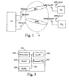
- Fig. 3 is a diagram representing the architecture of the spatial multiplexer of the base station according to the present invention.
- the spatial multiplexer 100 of the base station 10 has, for example, an architecture based on components connected together by a bus 301 and a processor 300 controlled by programs as disclosed in the Figs. 4, 5, 6 or 7.
- the bus 301 links the processor 300 to a read only memory ROM 302, a random access memory RAM 303, a vector interface 306 and a channel interface 305.
- the memory 303 contains registers intended to receive variables, and the instructions of the programs related to the algorithm as disclosed in the Figs. 4, 5, 6 or 7.
- the read only memory 302 contains instructions of the programs related to the algorithm as disclosed in the Figs. 4, 5, 6 or 7 which are transferred, when the base station 10 is powered on to the random access memory 303.
- the vector interface 306 enables the transfer of the downlink weighting vectors w 1D to w ND of the base station 10 to the respective multipliers Mul 11D to Mul NND .
- the vector interface 306 enables the transfer of the uplink weighting vectors w 1U to w NU of the base station 10 to the respective multipliers Mul 11U to Mul NNU .
- the vector interface 306 enables also the transfer of the downlink and uplink weighting vectors v 1D to v ND , v 1U to v NU to be used by the terminals 20 k in order to receive or transfer at least a group of data according to the invention.
- Such downlink and uplink weighting vectors v 1D to v ND , v 1U to v NU are transferred to the respective terminals 20 within at least a group of data or, by determining downlink weighting vectors of the base station 10 which are related to the weighting vector v 1D to v ND or v 1U to v NU.
- the weighting vector v 1D to v ND are not transferred by the base station 10.
- the base station 10 transfers then at least nmax pilot signals which are weighted by the downlink weighting vectors w 1D to w ND of the base station 10 which are related to the weighting vectors v 1D to v ND or v 1U to v NU .
- Each determined terminal 20 receives at least a pilot signal from the base station 10, determines from the at least one received pilot signal, the downlink weighing vector v nU or v nU it has to use for weighting the signals representatives of the n -th group of data.
- the channel interface 305 is adapted for receiving pilot signals from the terminals 20 1 to 20 K and to perform an estimation of link conditions or in other words to perform, for each terminal 20 k , an estimation of the channel response matrix between the terminal 20 k and the base station 10.
- Fig. 4 is an algorithm executed by the base station which describes the general principle of the present invention.
- the present algorithm is executed each time the base station 10 has to transfer simultaneously at most N groups of data to at least one of the terminals 20 1 to 20 K .
- the base station 10 sets a variable noted n to 1.
- the variable n denotes the group of data under process.
- the base station 10 determines, which terminal 20 k among the at least two terminals 20, is involved in the transfer of the group of data through the link according to the determined information.
- the base station 10 determines at least a weighting vector to be used for the transfer of the group of data, the elements of the weighting vector weighting the signals representatives of the group of data transferred through at least two antennas.
- the base station 10 determines the system evaluation function for the group of data under process considering the at least one determined weighting vector at step S403.
- the base station 10 determines the system evaluation function for the group is acceptable or not.
- step S405 increments the variable n of one unit and returns to step S401 in order to consider the next group of data.
- the base station 10 moves to step S406 and selects, for each determined terminal 20, a modulation and coding scheme to be used for the transfer of the group of data of which they are involved in the transfer.
- Fig. 5 is an algorithm executed by the base station in order to determine a spatial multiplexing on the downlink channel according to a first mode of realisation of the present invention.
- the present algorithm is executed each time the base station 10 has to transfer simultaneously N groups of data to at least one of the terminals 20 1 to 20 K .
- the base station 10 transfers simultaneously, through its N antennas, N groups of data.
- the base station 10 calculates information representative of the achievable link conditions between the base station 10 and each of the K terminals 20 1 to 20 K and determines which terminal 20 or terminals 20 has or have to receive at least a group of data according to the determined information.
- the processor 300 sets a variable noted n to 1.
- the variable n denotes the group of data under process.
- the downlink weighting vector w ND of the base station 10 are mutually orthogonal.
- the processor 300 sets the variable k to one.
- the variable k denotes an indicia of the terminal 20 k under process.
- the processor 300 determines a matrix representative of the achievable link conditions for the terminal 20 k .
- the processor 300 determines at step S503, the matrix noted R kn which is the correlation matrix of interference and noise components for the terminal 20 k under process and the group of data n under process.
- the base station 10 has knowledge of the channel matrix H k and the noise power P kz .
- each channel matrix H k is obtained by measuring the complex amplitude of pilot signals transmitted individually by the terminal 20 k on the uplink channel.
- the interference-plus-noise power P kz is reported by the terminal 20 k on the uplink channel. It has to be noted here that, instead of reporting the interference-plus-noise power P kz , each the terminal 20 k reports other relevant parameters such as the signal to noise plus interference power ratio or any other channel quality indicators, from which the base station 10 can estimate the noise power P k z .
- the base station 10 uses presumable values of the interference-plus-noise power P kz instead of determining them from the reported values by the terminals 20.
- step S505 the processor 300 checks whether or not the variable k is equal to K . If k is different from K , the processor 300 moves to step S506 and increment the variable k of one and returns to step S503 already described.
- the processor 300 executes the loop comprising the steps S503 to S505 as far as a matrix representative of the achievable link conditions between each terminal 20 k and the base station 10 is determined.
- step S507 Once a matrix representative of the achievable link conditions is determined for each terminal 20 k , the processor 300 moves to step S507.
- the steps S501 to S506 correspond to the determination of K matrices, each matrix being representative of the achievable link conditions between the base station 10 and a terminal 20 k .
- the processor 300 determines the terminal 20 k to which the n -th group of data under process has to be sent as the one which has the largest achievable signal to noise plus interference power ratio (SINR).
- SINR signal to noise plus interference power ratio
- f k () is the identity function.
- SNR Signal to Noise Ratio
- function f k () ntroduces some priority, according to certain criterion or criteria, in the determination of the terminal 20 to which the n -th group of data under process has to be sent.
- k k ⁇ , where e ⁇ kn ⁇ denotes the eigenvector corresponding to largest the eigenvalue of the matrix ⁇ kn of the terminal k ⁇ determined at step S507.
- the processor 300 determines the terminal k ⁇ which has to receive the n -th group of data and selects, for n -th group of data, the downlink weighting vector w nD of the base station 10 which maximizes the SINR of the terminal k ⁇ .
- ⁇ kn E v nD T ⁇ a kn 2
- E v nD T ⁇ z n IN p 2 P s n ⁇ w nD H ⁇ H k H ⁇ R kn - 1 ⁇ H k ⁇ w nD .
- step S507 determined terminal 20 k is the one which has the largest achievable signal to noise plus interference power ratio among the terminals 20.
- the spatial multiplexer 100 preferably imposes the downlink weighting vectors of the base station 10 determined for two groups of data which are transmitted to two different terminals 20 to be mutually orthogonal.
- ⁇ kn Since the eigenvectors of ⁇ kn which correspond to non-zero eigenvalue are orthogonal to w 1 D ,...,W ( n -1) D , ⁇ kn is maximized to P s n ⁇ ⁇ ⁇ ⁇ kn ⁇ .
- the processor 300 checks if the variable n is equal to N . If n is different from N, the processor 300 moves to step S510, increments the variable n of one and move to step S501 in order to consider the next group of data.
- the processor 300 executes the loop made by the steps S501 to S510.
- step S511 the processor 300 moves to step S511.
- the processor 300 determines the expected SINR of each of the terminals 20 determined at step S507 as P s n ⁇ ⁇ ⁇ ⁇ kn ⁇
- k k ⁇ .
- the spatial multiplexer 100 adds the ( n +1)-th group of data in the presence of the first to n -th groups of data.
- the received SINR of the n -th group of data is not modified after the ( n +1)-th group of data is added.
- the received SINR of the determined group of data is kept even if more groups of data are added by the spatial multiplexer 100.
- the processor 300 determines, for each of the terminals 20 determined at step S507, the modulation and coding scheme to be used by each of the determined terminals 20 for the downlink channel.
- the processor 300 transfers the elements of the downlink weighting vectors w 1 to w N of the base station 10 determined at step S508 to the multiplication modules noted Mul 11D to Mul NND , transfers the ordered list of the determined terminals 20 at step S507 to an allocation module not shown in the Fig. 3 which selects, for each of the determined terminals 20, a group of data which has a destination address equals to the determined terminal 20.
- the groups of data are then transferred by the base station 10.
- the information related to the modulation and the coding scheme to be used by determined terminals 20 for the downlink channel are also transferred in a time slot of the downlink channel.
- Each terminal 20 checks in the received group of data, the destination terminal identifier. If the identifier corresponds to its one, the terminal 20 identifies the modulation and coding scheme to be used for the downlink channel.
- Fig. 6 is an algorithm executed by the base station in order to determine the spatial multiplexing on the uplink channel according to the first mode of realisation of the present invention.
- the base station 10 is able to receive simultaneously nmax signals representatives of nmax groups of data through the uplink channel.
- the base station 10 decides which terminal 20 has to transfer each of the group of data on the uplink channel.
- the terminal 20 k If the terminal 20 k is determined to send the n -th group of data, the terminal 20 k performs beamforming based on a M k * 1 weighting vector v nU transferred by the base station 10.
- the processor 300 sets a variable noted n to 1.
- the variable n denotes the group of data under process.
- the processor 300 calculates the correlation matrix R n of interference and noise components which is given by :
- H k is the channel matrix between the terminal 20 k and the base station 10
- Hk (l) is the channel matrix between the second telecommunication device k which has already been determined to send the l -th group of data and the first telecommunication device
- () * denotes the complex conjugate of ()
- the base station 10 has knowledge of the channel matrix Hk (l) on the same manner as disclosed for H k in the Fig. 5.
- the processor 300 sets the variable k to one.
- the variable k denotes an indicia of the terminal 20 k under process.
- the processor 300 calculates the matrix representative of the achievable link conditions between the terminal 20 k and the base station 10 using the following formula : H k * ⁇ R n - 1 ⁇ H k T .
- the processor 300 checks whether or not the variable k is equal to K .
- step S605 If k is different from K, the processor 300 moves to step S605, increments k of one and returns to steps S603.
- the processor 300 executes the loop made by the steps S603 to S605.
- step S606 If k is equal to K , the processor 300 moves to step S606.
- the steps S601 to S605 correspond to the determination of K matrices, each matrix being representative of the achievable link conditions between the base station 10 and a terminal 20 k .
- the processor 300 determines the terminal 20 k which has to transfer the n -th group of data under process as the one which has the largest achievable signal to noise plus interference power ratio (SINR).
- SINR signal to noise plus interference power ratio
- f k () is the identity function.
- SNR Signal to Noise Ratio
- function f k () introduces some priority, according to certain criterion or criteria, in the determination of the terminal 20 to which the n -th group of data under process has to be sent.
- k k ⁇ , where e ⁇ H k * ⁇ R n - 1 ⁇ H k T ⁇
- k k ⁇ denotes the eigenvector corresponding to largest the eigenvalue of the matrix H k * ⁇ R n - 1 ⁇ H k T of the terminal k ⁇ determined at step S606.
- the processor 300 determines the terminal k ⁇ which has to transfer the n -th group of data and selects an uplink weighting vector v nU for the determined terminal 20 and for the group of data n under process which maximizes the SINR of the terminal k ⁇ .
- the signal to be weighted prior to be transferred by the determined terminal 20 s n ( p ) which is related to the n -th group of data, has a power P s n and E ⁇
- 2 1 ⁇ .
- the p -th sample x BS ( p ) [ x BS, 1 ( p ), ...
- ⁇ k ⁇ n E w nU T ⁇ b n 2
- E w nU T ⁇ z n p 2 P s n ⁇ v nU H ⁇ H k H ⁇ R n - 1 ⁇ H k T ⁇ v nU .
- step S606 the determined terminal 20 k is the one which has the largest achievable signal to noise plus interference power ratio among the terminals 20.
- the n -th group of data may deteriorate the SINRs of previously determined first to ( n -1)-th groups of data.
- the processor 300 determines a system evaluation function ⁇ ( n ) for the group of data under process.
- T( ⁇ ) is implemented under the form of a lookup table stored in the ROM memory 302 of the base station 10. If the SINR is comprised between zero and one dB, the throughput is equal to 0.250. If the SINR is comprised between one and two dBs, the throughput is equal to 0.285. If the SINR is comprised between two and three dBs, the throughput is equal to 0.333. If the SINR is around twenty dBs, the throughput is equal to 3.00.
- the steps S607 to S609 correspond to an evaluation of the system performance considering the uplink weighting vectors v nU for the determined terminals 20.
- the processor 300 checks whether or not the system evaluation function ⁇ ( n ) for the group of data under process is upper than or equal to the evaluation function ⁇ ( n -1) determined for the previous processed group of data.
- step S611 the processor 300 checks if the variable n is equal to N . If n is different from N, the processor 300 moves to step S612, increments the variable n of one and returns to step S601. The processor 300 executes the loop made by the steps S601 to S612 as far as all the N groups of data have not been processed or if ⁇ ( n ) ⁇ ⁇ ( n -1).
- the processor 300 determines, for each of the terminals 20 determined at step S606, the modulation and coding scheme to be used by the determined terminals 20 at step S606 for the uplink channel.
- the modulation is QPSK modulation with a coding rate of 1/8. If the SINR is comprised between one and two dBs, the modulation is QPSK modulation with a coding rate of 1/7. If the SINR is comprised between two and three dBs, the modulation is QPSK modulation with a coding rate of 1/6. If the SINR is around twenty dBs, the modulation is 16QAM with a coding rate of 3 ⁇ 4.
- the processor 300 transfers the ordered list of the determined terminals at step S606, the corresponding uplink weighting vectors v nU determined at step S607 for each of the terminals 20 comprised in the ordered list to an allocation module not shown in the Fig. 3.
- the allocation module inserts, as example within a timeslot of the downlink channel the ordered list of determined terminals 20 at step S606, the corresponding uplink weighting vectors v nU and information related to the modulation and coding scheme determined at step S613 for each determined terminal 20.
- Such information are then transferred through the downlink channel.
- the processor 300 determines other downlink weighting vectors w' nD of the base station 10 as follow: the processor 300 transfers information related to the determined uplink weighting vector v kU to the terminal 20 k by weighting the transferred pilot signals to the terminal 20 k by downlink weighting vectors w' nD of the base station 10 which enable each determined terminal 20, using the weighted pilot signals to determine the uplink weighting vector v kU .
- Such weighted pilot signals are transferred as example in a predetermined downlink time slot.
- Fig. 7 is an algorithm executed by the base station in order to determine the spatial multiplexing on the downlink channel according to a second mode of realisation of the present invention.
- the present algorithm is executed each time the base station 10 has to transfer simultaneously at most N groups of data to at least one of the terminals 20 1 to 20 K .
- the base station 10 transfers simultaneously, through its N antennas, the signals representatives of nmax groups of data, wherein nmax ⁇ N.
- the base station 10 calculates K matrices, each matrix being representative of the achievable link conditions between a terminal 20k and the base station 10 and determines which terminal or terminals 20 has to receive at least a group of data according to the calculated matrices.
- the base station 10 determines for each of the nmax groups of data transferred simultaneously, a downlink weighting vector w nD of the base station 10, the element of which multiply each duplicated signal to be transferred and a downlink weighting vector v nD for each n -th group of data.
- the processor 300 sets a variable noted n to 1.
- the variable n denotes the group of data under process.
- the base station 10 has knowledge of the channel matrix Hk (l) on the same manner as disclosed for H k in the Fig. 5.
- the processor 300 sets the variable k to one.
- the variable k denotes an indicia of the terminal 20 k under process.
- the processor 300 calculates the matrix representative of the achievable link conditions between the terminal 20 k under process and the base station 10 using the following formula : H k * ⁇ ⁇ n ⁇ H k T .
- the processor 300 checks whether or not the variable k is equal to K .
- step S706 increments k of one and returns to steps S704.
- the processor 300 executes the loop made by the steps S704 to S706.
- step S707 If k is equal to K , the processor 300 moves to step S707.
- the steps S701 to S706 correspond to the determination of K matrices, each matrix being representative of the achievable link conditions between the base station 10 and a terminal 20 k .
- the processor 300 determines the terminal 20 to which the n -th group of data under process has to be sent as the one which has the largest achievable signal to noise plus interference power ratio.
- P s is the power of the signal transferred by the base station 10 through its antennas BSAnt1 to BSAntN and P kz is the noise power matrix for the terminal 20 k .
- f k denotes a priority coefficient allocated to the terminal 20 k .
- the present algorithm is efficient when some terminals 20 have a reduced number of antennas in comparison with other terminals 20. Even if terminals 20 have the same P s P kz , a terminal 20 which has more antennas has on average larger eigenvalue ⁇ ⁇ H k * ⁇ ⁇ n ⁇ H k T ⁇ thanks to the terminal's signal weighting. Using the power ⁇ , a priority can be given according to the number of antennas a terminal 20 has. A priority can then be given to a terminal 20 which has a reduced number of M k antennas.
- the processor 300 determines the terminal k ⁇ which has to receive the n -th group of data and selects a downlink weighting vector v nD for the determined terminal 20 and for the group of data n under process which maximizes the SINR of the terminal k ⁇ .
- H k is the channel matrix of the determined terminal 20 k at step S707.
- the processor 300 determines a system evaluation function ⁇ ( n ) for the group of data under process.
- T( ⁇ l ) is similar as the one disclosed at step S609, it will not be described anymore.
- the steps S708 to S710 correspond to an evaluation of the system performance considering the uplink weighting vectors v nD for the determined terminals 20.
- the processor 300 checks whether or not the system evaluation function ⁇ ( n ) for the group of data under process is upper than or equal to the evaluation function ⁇ ( n -1) determined for the previous processed group of data.
- the processor 300 checks if the variable n is equal to N. If n is different from N, the processor 300 moves to step S713, increments the variable n of one and returns to step S701. The processor 300 executes the loop made by the steps S701 to S713 as far as all the N groups of data have not been processed or if ⁇ ( n ) ⁇ ⁇ ( n -1).
- the processor 300 determines, for each of the terminals 20 determined at step S707 the modulation and coding scheme to be used by the determined terminals 20 for the downlink channel. Such determination is as example, as the one disclosed at step S613 of the Fig. 6.
- H k(l) is the channel matrix between the terminal 20 k and the base station 10 which have been determined to receive the l -th group of data on the downlink channel and v lD is the terminal downlink weighting vector determined for the l -th group of data.
- step S707 the determined terminal 20 k is the one which has the largest achievable signal to noise plus interference power ratio among the terminals 20.
- the processor 300 transfers the elements of the downlink weighting vectors w l to w nmax of the base station 10 determined at step S715 to the multiplication modules noted Mul 11 to Mul NN , transfers the ordered list of the determined terminals 20 at step S707 to an allocation module not shown in the Fig. 3.
- the allocation module selects, for each of the determined terminal 20, a group of data which has a destination address equals to the determined terminal 20.
- the groups of data are then transferred by the base station 10.
- the information related to the modulation and the coding scheme to be used by determined terminals 20 for the downlink channel are also transferred in a time slot of the downlink channel.
- Each of the determined terminal 20 receives pilot signals and determines the downlink weighting vector based on the minimum-mean-square-error weight.
- Each terminal 20 checks in the received group of data the destination terminal identifier and if the identified corresponds to its one, the terminal 20 identifies the modulation and coding scheme used for the downlink channel and reads the data.
Abstract
Description
- The present invention relates generally to communication systems and in particular, to a method and apparatus for controlling the transfer of signals representatives of a group of data in a wireless telecommunication network.
- Telecommunication systems in which, a plurality of antennas are used at a receiver end and/or at a transmitter end of a wireless link, are called Multiple Input Multiple Output systems (further referred to as MIMO systems). MIMO systems have been shown to offer large transmission capacities compared to those offered by single antenna systems. In particular, MIMO capacity increases linearly with the number of transmitting or receiving antennas, whichever the smallest, for a given Signal-to-Noise Ratio and under favourable uncorrelated channel conditions.
- Beamforming has been investigated for MIMO systems in order to optimize the range and performance of the wireless link between the receiver end and the transmitter end. Multiple-input multiple-output (MIMO) scheme with beamforming uses antenna signal processing at both ends of the wireless link to maximize the signal-to-noise power ratio (SNR) and/or signal-to-noise-plus-interference power ratio (SNIR), thereby improving the link margin between two telecommunication devices.
- Spatial multiplexing methods have been proposed in MIMO systems. In a spatial multiplexing system, at least two independent data streams are transmitted using at least two transmitting antennas respectively. In a receiving end, at least two antennas are used and each antenna receives at least two signals simultaneously. Therefore, the received signals must be recovered separately with a detection algorithm for each signal. The separated signals are decoded independently.
- In case of a telecommunication system wherein plural terminals are linked to a base station, it is difficult sometime for the terminals to determine the best weighting vector which weights the signals received or transferred through its antennas as far as it is not aware about the other terminals which are linked to the base station and which may disturb its communication with the base station.
- Furthermore, when a single terminal is linked to a base station, or in a point to point communication, the terminal is not aware if there are some other base stations and terminals linked to them in the vicinity of the terminal. Such unawareness of the communication condition on the wireless link limits the ability of a terminal to determine the best weighting vector it has to apply to signals transferred or received through its antennas.
- The aim of the invention is therefore to propose a method, and a device which allow telecommunication devices to use the best weighting vectors in order to perform efficient beamforming and to propose a method, and a device which allow in a simple and efficient way the allocation of the radio resources of the wireless network.
- To that end, the present invention concerns a method for controlling the transfer of signals representatives of a group of data in a wireless telecommunication network comprising a first telecommunication device linked through plural second telecommunication devices through the wireless network, the first telecommunication device comprising at least two antennas, at least one of the second telecommunication devices comprising at least two antennas, characterised in that the method comprises the steps executed by the first telecommunication device of:
- calculating at least two information, each information being representative of the achievable link conditions between the first telecommunication device and one second telecommunication device,
- determining which second telecommunication device, among the at least two second telecommunication devices, is involved in the transfer of the group of data through the link according to the determined information,
- determining at least a weighting vector to be used for the transfer of the group of data, the elements of the weighting vector weighting the signals representatives of the group of data transferred through at least two antennas.
- The present invention concerns also a device for controlling the transfer of signals representatives of a group of data in a wireless telecommunication network comprising a first telecommunication device linked through plural second telecommunication devices through the wireless network, the first telecommunication device comprising at least two antennas, at least one of the second telecommunication devices comprising at least two antennas, characterised in that the device is include in the first telecommunication device and comprises:
- means for calculating at least two information, each information being representative of the achievable link conditions between the first telecommunication device and one second telecommunication device,
- means for determining which second telecommunication device, among the at least two second telecommunication devices, is involved in the transfer of the group of data through the link according to the determined information,
- means for determining at least a weighting vector to be used for the transfer of the group of data, the elements of the weighting vector weighting the signals representatives of the group of data transferred through at least two antennas.
- Thus, if the first telecommunication device is aware of any other telecommunication devices which may disturb the transfer of information between the first and the second telecommunication devices, the determination of the weighting vector can be made considering these disturbances.
- Furthermore, the first telecommunication device can then control the weighting made by at least one second telecommunication device on the signals transferred between the first telecommunication device and the second telecommunication device.
- Such case is particularly effective when the first telecommunication device is a base station and the second telecommunication device is a terminal.
- Furthermore, by determining which second telecommunication device, among the at least two second telecommunication devices, is involved in the transfer of the group of data through the link according to information representative of the achievable link conditions between the first telecommunication device and the second telecommunication devices, it is possible to allocate the radio resources of the wireless network in an efficient way.
- According to a first advantageous embodiment, the determination of the second device involved in the transfer of the group of data through the link is made also according to the number of antennas of each second telecommunication device.
- Thus some priority can be given to second telecommunication devices according to their respective number of antennas.
- According to a second advantageous embodiment, each information representative of the achievable link conditions between the first telecommunication device and one second telecommunication device is a matrix representative of the achievable link conditions between the first telecommunication device and the second telecommunication device.
- According to a third advantageous embodiment, the modulation and coding scheme to be used by the second telecommunication device involved in the transfer of the group of data are determined.
- Thus, the use of the resources of the wireless network is optimized.
- Furthermore, as the first telecommunication device determines the modulation and coding scheme to be used by the second telecommunication device involved in the transfer of the group of data, the second telecommunication device doesn't need to comprise complex processing capabilities.
- According to a fourth advantageous embodiment, the determination of the modulation and coding scheme to be used by the second telecommunication device involved in the transfer of the group of data is made using the determined weighting vector.
- Thus, the determination of the modulation and coding scheme is more accurate and takes profit of the determination of the weighting vector.
- According to a fifth advantageous embodiment, the determined second telecommunication device is the second telecommunication device which is expected to receive signals representatives of the group of data transferred by the first telecommunication device.
- Thus, the first telecommunication device determines to which second telecommunication device, the group of information should be sent according to each calculated matrices representatives of the achievable link conditions between the first telecommunication device and the second telecommunication device.
- According to a sixth advantageous embodiment, the at least one weighting vector to be used for the transfer of the group of data, is a weighting vector which weights the signals representatives of the group of data transferred by the first telecommunication device.
- Thus, the first telecommunication device can perform beamforming.
- According to a seventh advantageous embodiment, the first telecommunication device comprises N antennas, at most N groups of data are transferred simultaneously through the N antennas, and in that it is determined successively, for each group of data of the at most N groups of data, the second telecommunication device involved in the transfer of the group of data and the weighting vector to be used for the transfer of the group of data.
- Thus the determination of the second telecommunication devices is simple and doesn't need any iterative process.
- According to a eighth advantageous embodiment, the second telecommunication device involved in the transfer of a group of data is determined by:
- calculating a matrix Un using the following formula :

wherein I is the identity matrix, n is the identifier of the group of data for which the control of the transfer of the signals representatives of the group of data is currently done, l=1 to n-1 are the identifiers of the groups of data for which the control of the transfer of the signals representatives of the group of data is already done, wID is the weighting vector which weights the signals transferred by the first telecommunication device determined for the l-th group of data, () H is the complex conjugate transpose of (), - calculating, for each second telecommunication device k, with k=1 to K, K is the number of second telecommunication devices, a matrix Rkn which is the correlation matrix of interference and noise components for the second telecommunication device k,


- calculating, for each second telecommunication device k, a matrix

- determining among the K second telecommunication devices, the second telecommunication device k̂as one involved in the transfer of the group of data which satisfies the following formula : k̂ = arg k max fk (ρ〈Ψ kn 〉), where ρ〈.〉 is the largest eigenvalue of the matrix 〈·〉, argk max represents the second telecommunication device k which has the largest value of fk (ρ〈Ψ kn 〉), fk () is a priority function.
- Thus, the determination of each second telecommunication device is made without complex calculation and/or without any iteration process.
- According to a ninth advantageous embodiment, the priority function fk () is the identity function or a function which weights the largest eigenvalue of the matrix Ψ kn by an averaged Signal to Noise Ratio over a long period of time or a wide frequency band or by the number of antennas of the second telecommunication device.
- Thus, when the priority function fk () is the identity function, the determination of the second telecommunication device is made using only the largest eigenvalue of the calculated matrices. Using only the largest eigenvalue, the present invention enables the determination of each second telecommunication device which enables to reach a high achievable signal to noise plus interference power ratio for each of the determined second telecommunication device.
- Furthermore, using the averaged Signal to Noise Ratio or the number of antennas of the second telecommunication device, it is possible to determine the second telecommunication device according to other criterion.
- According to a tenth advantageous embodiment, the weighting vector which weights the signals representatives of the group of data is determined for each group of data according to the following formula : wnD =e〈Ψ kn〉, where e〈Ψ kn〉 is the eigenvector corresponding to the largest eigenvalue of the matrix Ψ kn of the second telecommunication device involved in the transfer of the n-th group of data.
- Thus, the achievable signal to noise plus interference power ratio of each determined second telecommunication device is maximized.
- According to a eleventh advantageous embodiment, an achievable signal to noise plus interference power ratio is determined, for each determined second telecommunication device which is expected to receive signals representatives of the group of data, from the determined weighting vector which weights the signals representatives of the group of data transferred to the second telecommunication device.
- According to a twelfth advantageous embodiment which may be used in combination with any of the first to fifth embodiments, the determined second telecommunication device is the second telecommunication device which is expected to transfer signals representatives of the group of data to the first telecommunication device.
- Thus, the first telecommunication device determines which second telecommunication device should send the group of information according to each calculated matrices representative of the achievable link conditions between the first telecommunication and the second telecommunication device.
- According to a thirteenth advantageous embodiment, the at least one weighting vector to be used for the transfer of the group of data, is a weighting vector which weights the signals representatives of the group of data transferred by the second telecommunication device.
- Thus, the second telecommunication device can perform beamforming.
- According to a fourteenth advantageous embodiment, the first telecommunication device comprises N antennas, at most N groups of data are received simultaneously through the N antennas, and in that it is determined successively, for each group of data of the at most N groups of data, the second telecommunication device involved in the transfer of the group of data and the weighting vector to be used for the transfer of the group of data.
- Thus the determination of the second telecommunication devices is simple and doesn't need any iterative process.
- According to a fifteenth advantageous embodiment, the second telecommunication device involved in the transfer of a group of data is determined by:
- calculating the correlation matrix Rn of interference and noise components which is given by :
- calculating, for each second telecommunication device k, a matrix

- determining among the K second telecommunication devices, the second telecommunication device k̂ as the one involved in the transfer of the group of data which satisfies the following formula :
- Thus, the determination of the second telecommunication devices is determined without complex calculation and/or without any iteration process.
- According to a sixteenth advantageous embodiment, the weighting vector which weights the signals representatives of the group of data is determined for each group of data according to the following formula :


- Thus, the achievable signal to noise plus interference power ratio of each determined second telecommunication device is maximized.
- According to a seventeenth advantageous embodiment, an achievable signal to noise plus interference power ratio is further determined, for each determined second telecommunication device, from the determined weighting vector which weights the signals representatives of the group of data transferred to the second telecommunication device.
- According to a eighteenth advantageous embodiment, which is used in combination with the fifth embodiment, two weighting vectors are determined, a weighting vector wnD which weights the signals representatives of the group of data transferred by the first telecommunication device and a weighting vector vnD which weights the signals representatives of the group of data received by the second telecommunication device.
- Thus, the first and second telecommunication devices can perform beamforming.
- According to a nineteenth advantageous embodiment, the second telecommunication device involved in the transfer of a group of data is determined by:
- calculating a matrix B̅n = ∟H k(1) v 1D ,,..., H k(n-1) v (n-1) D, ┘, n is the identifier of the group of data for which the control of the transfer of the signals representatives of the group of data is currently done, l=1 to n-1 are the identifiers of the groups of data for which the control of the transfer of the signals representatives of the group of data is already done where Hk(l) is the channel matrix of the second telecommunication k which is expected to receive signals representatives of the l-th group of data transferred by the first telecommunication device, vlD is the weighting vector which weights the signals representatives of the group of data determined for the l-th group of data,
- calculating a matrix

- calculating, for each second telecommunication device k, k=1 to K, K is the number of second telecommunication devices, a matrix

- determining among the K second telecommunication devices, the second telecommunication device k̂ as the one involved in the transfer of the group of data which satisfies the following formula :


- Thus, the determination of the second telecommunication devices is determined without complex calculation and/or without any iteration process.
- According to a twentieth advantageous embodiment, the weighting vector vnD which weights the signals representatives of the group of data transferred by the second telecommunication device is calculating using the following formula:


- According to a twenty-first advantageous embodiment, each weighting vector wnD which weights the signals transferred by the first telecommunication device to the determined second telecommunication device for the n-th group of data is calculating using the following formula:

- where

- B = [b 1 ,..., b nmax ],
-

- According to still another aspect, the present invention concerns a computer program which can be directly loadable into a programmable device, comprising instructions or portions of code for implementing the steps of the method according to the invention, when said computer programs are executed on a programmable device.
- Since the features and advantages relating to the computer program are the same as those set out above related to the method and device according to the invention, they will not be repeated here.
- The characteristics of the invention will emerge more clearly from a reading of the following description of an example embodiment, the said description being produced with reference to the accompanying drawings, among which :
- Fig. 1 is a diagram representing the architecture of the system according to the present invention ;
- Fig. 2 is a diagram representing the architecture of a base station according to the present invention ;
- Fig. 3 is a diagram representing the architecture of the spatial multiplexer of the base station according to the present invention ;
- Fig. 4 is an algorithm executed by the base station which describes the general principle of the present invention ;
- Fig. 5 is an algorithm executed by the base station in order to determine a spatial multiplexing on the downlink channel according to a first mode of realisation of the present invention ;
- Fig. 6 is an algorithm executed by the base station in order to determine the spatial multiplexing on the uplink channel according to a first mode of realisation of the present invention ;
- Fig. 7 is an algorithm executed by the base station in order to determine the spatial multiplexing on the downlink channel according to a second mode of realisation of the present invention.
- Fig. 1 is a diagram representing the architecture of the system according to the present invention.
- In the system of the Fig. 1, a plurality of
second telecommunication devices 201 to 20K are linked through awireless network 15 to afirst telecommunication device 10 using an uplink and a downlink channel. - Preferably, and in a non limitative way, the
first telecommunication device 10 is abase station 10 or a node of thewireless network 15. Thesecond telecommunication devices 20, to 20K are terminals like mobile phones or personal computers. - The
base station 10 has N antennas noted BSAnt1 to BSAntN. Theterminals 201 to 20K have M k antennas noted respectively MSAnt1 to MSAntM and MSKAnt1 to MSKAntM. It has to be noted here that the number of Mk antennas may vary according to each terminal 20k with k=1 to K. At least one of theterminals 201 to 20K has at least two antennas. - The
base station 10 transfers signals representatives of a group of data to theterminals 201 to 20K through the downlink channel and theterminals 201 to 20K transfer signals to thebase station 10 through the uplink channel. - When the system uses Time Division Duplexing scheme, the signals transferred in uplink and downlink channels are duplexed in different time periods of the same frequency band. The signals transferred within the
wireless network 15 share the same frequency spectrum. The share spectrum is time divided using repeating frames having a fixed number of time slots. Each time slot is used to transmit either on uplink or downlink signals. - When the system uses Frequency Division Duplexing scheme, the signals transferred in uplink and downlink channels are duplexed in different frequency bands. The spectrum is divided into different frequency bands and the uplink and downlink signals are transmitted simultaneously.
- The
base station 10 transfers through the antennas BSAnt1 to BsAntN the signals to be transmitted to theterminals 201 to 20K. More precisely, when thebase station 10 transmits signals representatives of a group of data to a giventerminal 20k through the downlink channel, the signals are N times duplicated and each duplicated signal is weighted, i.e. multiplied, by an element of a downlink weighting vector wnD of thebase station 10. - The
base station 10 receives through the antennas BSAnt1 to BsAntN the signals transmitted by theterminals 201 to 20K. More precisely, when thebase station 10 receives signals representatives of a group of data from a giventerminal 20k with k=1 to K through the uplink channel, each signal received by each of its antennas BSAnt1 to BsAntN is weighted, i.e. multiplied, by an element of an uplink weighting vector wnU of thebase station 10. - According to the invention, the weighting vectors wnD, and/or wnU, are determined by the
base station 10 for each of the n groups of data received simultaneously, where n = 1 to at most N, to be transferred or received by thebase station 10. As a result, thebase station 10 and each terminal 20k performs beamforming, i.e. controls the spatial direction of the transmitted or received signals. - The ellipse noted BF1 in the Fig. 1 shows the pattern of the radiated signals by the antennas BSAnt1 to BSAntN transferred to the terminal 201 by the
base station 10. - The ellipse noted BFK in the Fig. 1 shows the pattern of the radiated signals by the antennas BSAnt1 to BSAntN transferred to the terminal 20K by the
base station 10. - The
base station 10 further determines the weighting vectors vnD and/or vnU , with n=1 to nmax, that each terminal 20k , where k =1 to K, has to use for weighting the signals representatives of group of data, received and/or transmitted through the antennas MSkAnt1 to MSkAntM. Thebase station 10 transfers to a giventerminal 20k the weighting vectors vnD and/or vnU by transferring the elements of weighting vector vnD and/or vnU within a group of data. - It has to be noted here that, in a variant of realization, the
base station 10 doesn't transfer the weighting vectors vnD to theterminals 20. Each terminal 20k determines by itself the downlink weighting vector it uses. - In another variant of realisation, the
base station 10 transfers to the terminal 20k which is determined to transfer a group of information n the determined information related to the weighting vector vnU, and transfers to the terminal 20k through thewireless network 15 at least a signal being weighted by the information related to the determined weighting vector vnU . - More precisely, each weighting vector vnD is determined for each group of data n to be transferred simultaneously in the downlink channel or each weighting vector vnU is determined for each group of data n to be transferred simultaneously in the uplink channel.
- Then, each terminal 20k transfers, through its antennas MSkAnt1 to MSkAntM, the signals representatives of a group of data to be transmitted to the
base station 10. More precisely, when a terminal 20k transmits signals representatives of a group of data to thebase station 10 through the uplink channel, the signals are Mk times duplicated and each duplicated signal is weighted, i.e. multiplied, by an element of an uplink weighting vector vnU determined for the terminal 20k which is determined to receive the n-th group of data. - The ellipse BF1 shows the pattern of the radiated signals by the antennas MS1Ant1 to MS1AntM transferred by the terminal 201 to the
base station 10. - The ellipse BFK shows the pattern of the radiated signals by the antennas MSKAnt1 to MSKAntM transferred by the terminal 20K to the
base station 10. - Each terminal 20k receives, through its antennas MSkAnt1 to MSkAntM, signals transmitted by the
base station 10. More precisely, when a terminal 20k receives signals from thebase station 10 through the downlink channel, each signal received by each of its antennas MSkAnt1 to MSkAntM is weighted, i.e. multiplied, by an element of the determined downlink weighting vector vnD for the terminal 20k which is determined to receive the n-th group of data. - As a result, the terminal 20k performs beamforming, i.e. controls the spatial direction of the received signals from the
base station 10. - According to the variant of realization, each terminal 20k determines by itself the downlink weighting vector it has to use.
- According to the other variant of realization, each terminal 20k receives from the
base station 10 plural signals through the downlink channel and calculates from the received signals the weighting vector vnD it has to use when it receives signals from thebase station 10 through the downlink channel. Each terminal 20k receives from thebase station 10 plural signals through the downlink channel and calculates from the received signal or signals the weighting vector vnU it has to use when it transfers signals to thebase station 10 through the uplink channel. - Fig. 2 is a diagram representing the architecture of a base station according to the present invention.
- The
base station 10 comprises aspatial multiplexer 100, N duplication modules noted Cp1 to CPN, N*N downlink multiplication modules noted Mul11D to MulNND, N downlink summation modules noted Sum1D to SumND, N*N uplink multiplication modules noted Mul11U to MulNNU, N uplink summation modules noted Sum1U to SumNU. - According to the invention, the
base station 10 transfers simultaneously, through the downlink channel, at most N groups of data. Thespatial multiplexer 100 determines information which are representative of the achievable link conditions between thebase station 10 and each terminal 20k. Thespatial multiplexer 100 determines, for each of the at most N groups of data, the terminal 20k which has to receive the group of data according to the determined information which are representative of the achievable link conditions. Thebase station 10 receives simultaneously, through the uplink channel, nmax groups of data with nmax ≤ N. Thespatial multiplexer 100 determines, for each of the nmax groups of data to be received, the terminal 20k which has to transfer the group of data to thebase station 10 according to the determined information representative of the achievable link conditions. - The signals S1(t) to SN(t) are the signals, which are respectively representative of N groups of data, to be transferred to the
K terminals 201 to 20K linked to thebase station 10. Each of the signals S1(t) to SN(t) are N times duplicated by a respective duplication module Cp1 to CPN. For each signal to be transferred to a terminal 20k with k=1 to K, each duplicated signal is weighted by the elements of a downlink weighting vector wnD corresponding to the group of data noted n to be transferred to the terminal 20k and determined by thespatial multiplexer 100. The combination of each signals transferred to a terminal 20k by the antennas BSAnt1 to BSAntN is called beamforming signal. - The signals weighted by the first element of each downlink weighting vector wnD of the
base station 10 are then summed and transferred through the first antenna BSAnt1 of thebase station 10. The signals weighted by the second element of each weighting vector wnD of thebase station 10 are then summed and transferred through the second antenna BSAnt2 of thebase station 10 and so on until the N-th elements of the weighting vector w nD of thebase station 10. - It has to be noted here that the signals are prior to be transferred to each antenna BSAnt1 to BSAntN, frequency up converted, mapped and so on, as it is done in classical wireless telecommunication devices.
- The
base station 10 receives simultaneously nmax, with nmax ≤ N signals which are representative of nmax groups of data transferred by at least a part of theK terminals 201 to 20K. The signals received by each antenna BSAnt1 to BSAntN are respectively weighted, i.e. multiplied by the elements of an uplink weighting vector wnU of thebase station 10. - Each signal received through the
antenna BSAnt 1 is N times multiplied by the first elements (w11U,...wnmax1U) of the uplink weightings vectors w1U to wnamxU of thebase station 10. - Each signal received through the antenna BSAnt2 is N times multiplied by the second elements (w12U,....wnmax2U) of the uplink weightings vector w1U to wnmaxU of the
base station 10. - Each signal received through the antenna BSAntN is N times multiplied by the N-th elements (w1NU,... wnmaxNU) of the uplink weightings vector w 1U to w nmaxU of the
base station 10. - The signals weighted by the uplink weighting vector w1U of the
base station 10 are then added by a by an adder noted Sum1U in order to form the first received group of data. - The signals weighted by the uplink weighting vector wNU of the
base station 10 are then added by a by an adder noted SumNU in order to form the N-th received group of data. - It has to be noted here that the signals received from each antenna BSAnt1 to BSAntN are frequency down converted, demapped and so on, as it is done in classical wireless telecommunication devices.
- Fig. 3 is a diagram representing the architecture of the spatial multiplexer of the base station according to the present invention.
- The
spatial multiplexer 100 of thebase station 10 has, for example, an architecture based on components connected together by abus 301 and aprocessor 300 controlled by programs as disclosed in the Figs. 4, 5, 6 or 7. - The
bus 301 links theprocessor 300 to a read onlymemory ROM 302, a randomaccess memory RAM 303, avector interface 306 and achannel interface 305. - The
memory 303 contains registers intended to receive variables, and the instructions of the programs related to the algorithm as disclosed in the Figs. 4, 5, 6 or 7. - The
processor 300 determines the downlink weighting vectors wlD to wND of thebase station 10, the uplink weighting vectors w1U to wNU of thebase station 10, the downlink weighting vectors v1D to vND of theterminals 201 to 20K which have been determined to receive each group n of data with n = 1 to N and the uplink weighting vectors v1U to vNU of theterminals 20l to 20K which have been determined to transmit each group n ofdata 10 with n = 1 to nmax where nmax is ≤ N. - The read only
memory 302 contains instructions of the programs related to the algorithm as disclosed in the Figs. 4, 5, 6 or 7 which are transferred, when thebase station 10 is powered on to therandom access memory 303. - The
vector interface 306 enables the transfer of the downlink weighting vectors w 1D to wND of thebase station 10 to the respective multipliers Mul11D to MulNND. - The
vector interface 306 enables the transfer of the uplink weighting vectors w1U to wNU of thebase station 10 to the respective multipliers Mul11U to MulNNU. - The
vector interface 306 enables also the transfer of the downlink and uplink weighting vectors v1D to vND, v1U to vNU to be used by theterminals 20k in order to receive or transfer at least a group of data according to the invention. - Such downlink and uplink weighting vectors v1D to vND, v1U to vNU are transferred to the
respective terminals 20 within at least a group of data or, by determining downlink weighting vectors of thebase station 10 which are related to the weighting vector v1D to vND or v1U to vNU. - According to a variant of realisation, the weighting vector v1D to vND are not transferred by the
base station 10. - The
base station 10 transfers then at least nmax pilot signals which are weighted by the downlink weighting vectors w1D to wND of thebase station 10 which are related to the weighting vectors v1D to vND or v1U to vNU . Eachdetermined terminal 20 receives at least a pilot signal from thebase station 10, determines from the at least one received pilot signal, the downlink weighing vector vnU or vnU it has to use for weighting the signals representatives of the n-th group of data. - The
channel interface 305 is adapted for receiving pilot signals from theterminals 201 to 20K and to perform an estimation of link conditions or in other words to perform, for each terminal 20k, an estimation of the channel response matrix between the terminal 20k and thebase station 10. - Fig. 4 is an algorithm executed by the base station which describes the general principle of the present invention.
- The present algorithm is executed each time the
base station 10 has to transfer simultaneously at most N groups of data to at least one of theterminals 201 to 20K. - At step S400, the
base station 10 sets a variable noted n to 1. The variable n denotes the group of data under process. - At next step S401, the
base station 10 calculates at least two information, each information being representative of the achievable link conditions between the base station and oneterminal 20k with k=1 to K. - At next step S402, the
base station 10 determines, whichterminal 20k among the at least twoterminals 20, is involved in the transfer of the group of data through the link according to the determined information. - At next step S403, the
base station 10 determines at least a weighting vector to be used for the transfer of the group of data, the elements of the weighting vector weighting the signals representatives of the group of data transferred through at least two antennas. - At next step S403, the
base station 10 determines the system evaluation function for the group of data under process considering the at least one determined weighting vector at step S403. - At next step S404, the
base station 10 determines the system evaluation function for the group is acceptable or not. - If the system evaluation function for the group of data is acceptable, the
base station 10 moves to step S405, increments the variable n of one unit and returns to step S401 in order to consider the next group of data. - If the system evaluation function for the group of data is not acceptable, nmax group of data will be transferred simultaneously with nmax=n-1. The
base station 10 moves to step S406 and selects, for eachdetermined terminal 20, a modulation and coding scheme to be used for the transfer of the group of data of which they are involved in the transfer. - Fig. 5 is an algorithm executed by the base station in order to determine a spatial multiplexing on the downlink channel according to a first mode of realisation of the present invention.
- The present algorithm is executed each time the
base station 10 has to transfer simultaneously N groups of data to at least one of theterminals 201 to 20K. - The
base station 10 transfers simultaneously, through its N antennas, N groups of data. Thebase station 10 calculates information representative of the achievable link conditions between thebase station 10 and each of theK terminals 201 to 20K and determines which terminal 20 orterminals 20 has or have to receive at least a group of data according to the determined information. - According to the first mode of realisation of the invention, the
base station 10, determines for each transferred group of data n, where n = 1 to N is the indicia of a group of data, a downlink weighting vector wnD of thebase station 10. - More precisely the present algorithm is executed by the
processor 300 of thespatial multiplexer 100 of thebase station 10. - At step S500, the
processor 300 sets a variable noted n to 1. The variable n denotes the group of data under process. - At next step S501, the
processor 300 calculates the matrix Un using the following formula :
wherein I is the identity matrix, w 1D , for l=1 to n-1, are the downlink weighting vectors of thebase station 10 determined for the first to n-1 groups of data previously processed,
- It has to be noted here that the downlink weighting vector wND of the
base station 10 are mutually orthogonal. - At next step S502, the
processor 300 sets the variable k to one. The variable k denotes an indicia of the terminal 20k under process. - At next steps S503 and S504, the
processor 300 determines a matrix representative of the achievable link conditions for the terminal 20k. - More precisely, the
processor 300 determines at step S503, the matrix noted Rkn which is the correlation matrix of interference and noise components for the terminal 20k under process and the group of data n under process. Rkn is given by:
-

base station 10 through its antennas BSAnt1 to BSAntN. - Hk is the channel matrix between the terminal 20k and the
base station 10, Pkz is the noise power matrix for theterminals 20. - The
base station 10 has knowledge of the channel matrix Hk and the noise power Pkz . Classically, each channel matrix Hk is obtained by measuring the complex amplitude of pilot signals transmitted individually by the terminal 20k on the uplink channel. The interference-plus-noise power Pkz is reported by the terminal 20k on the uplink channel. It has to be noted here that, instead of reporting the interference-plus-noise power Pkz , each the terminal 20k reports other relevant parameters such as the signal to noise plus interference power ratio or any other channel quality indicators, from which thebase station 10 can estimate the noise power P kz. In a variant of realization thebase station 10 uses presumable values of the interference-plus-noise power Pkz instead of determining them from the reported values by theterminals 20. - At step S504, the
processor 300 calculates the matrix noted Ψ kn representative of the achievable link conditions between the terminal 20k and thebase station 10 using the following formula :
- At next step S505, the
processor 300 checks whether or not the variable k is equal to K. If k is different from K, theprocessor 300 moves to step S506 and increment the variable k of one and returns to step S503 already described. - The
processor 300 executes the loop comprising the steps S503 to S505 as far as a matrix representative of the achievable link conditions between each terminal 20k and thebase station 10 is determined. - Once a matrix representative of the achievable link conditions is determined for each terminal 20k, the
processor 300 moves to step S507. - The steps S501 to S506 correspond to the determination of K matrices, each matrix being representative of the achievable link conditions between the
base station 10 and a terminal 20k. - At step S507, the
processor 300 determines the terminal 20k to which the n-th group of data under process has to be sent as the one which has the largest achievable signal to noise plus interference power ratio (SINR). - More precisely, the
processor 300 determines, for the n-th group of data, the terminal noted k̂ which satisfies the following formula: k̂= arg k max fk (ρ 〈Ψ kn〉), where ρ〈·〉 is the largest eigenvalue of the matrix 〈·〉, argk max represents the terminal 20k which has the largest value of fk (ρ〈Ψ Kn 〉) and fk () is a priority function. - Preferably, fk () is the identity function.
- In a first variant of realisation, fk () is equal to :

- In a second variant of realisation, f k() is equal to :

- It has to be noted here that, many different functions fk () can be used in the present invention. Such function fk () ntroduces some priority, according to certain criterion or criteria, in the determination of the terminal 20 to which the n-th group of data under process has to be sent.
- At next step S508, the
processor 300 determines the downlink weighting vector of the base station 10 w nD for the group of data n under process using the following formula : wnD = e〈Ψ kn 〉| k= k̂ , where e〈Ψ kn 〉 denotes the eigenvector corresponding to largest the eigenvalue of the matrix Ψ kn of the terminal k̂ determined at step S507. - Thanks to steps S507 and S508, the
processor 300 determines the terminal k̂ which has to receive the n-th group of data and selects, for n-th group of data, the downlink weighting vector wnD of thebase station 10 which maximizes the SINR of the terminal k̂ . - It has to be noted here that, if we consider that the n-th group of data is sent to the k-th terminal in the presence of an n-1-th group of data which has been previously determined by the
spatial multiplexer 100, the k-th terminal's received signal is expressed as :


- The terminal 20k applies the weighting vector

- Then, the signal to noise plus interference power ratio γkn after weighting is expressed as:

- Such formula shows that at step S507, determined
terminal 20k is the one which has the largest achievable signal to noise plus interference power ratio among theterminals 20. - As disclosed above, the
spatial multiplexer 100 preferably imposes the downlink weighting vectors of thebase station 10 determined for two groups of data which are transmitted to twodifferent terminals 20 to be mutually orthogonal. The first to (n-1)-th groups of data being already determined, the n-th weight vector wnD satisfies the following equation: wnD = UnwnD with
- Then, the SINR γ kn of the terminal 20k to which the n-th group of data is transferred is equal to :

- Since the eigenvectors of Ψ kn which correspond to non-zero eigenvalue are orthogonal to w 1 D,...,W (n-1) D, γkn is maximized to

- At next step S509, the
processor 300 checks if the variable n is equal to N. If n is different from N, theprocessor 300 moves to step S510, increments the variable n of one and move to step S501 in order to consider the next group of data. - As far as all the N groups of data have not been processed, the
processor 300 executes the loop made by the steps S501 to S510. - Once the N groups of data have been processed, the
processor 300 moves to step S511. - At next step S511, the
processor 300 determines the expected SINR of each of theterminals 20 determined at step S507 as
- It has to be noted here that once the n-th group of data is determined, the
spatial multiplexer 100 adds the (n+1)-th group of data in the presence of the first to n-th groups of data. - It has to be noted here that the received SINR of the n-th group of data is not modified after the (n+1)-th group of data is added. In the same manner, the received SINR of the determined group of data is kept even if more groups of data are added by the
spatial multiplexer 100. - This characteristic is led by the orthogonality of the downlink weighting vectors wnD of the
base station 10 disclosed above. Using this characteristic, thespatial multiplexer 100 decides the downlink weighting vectors wnD of thebase station 10 and the terminal 20 which has to receive for the n-th group of data in the sequence n=1, ..., N without considering the effect of additional groups of data. - At next step S512, the
processor 300 determines, for each of theterminals 20 determined at step S507, the modulation and coding scheme to be used by each of thedetermined terminals 20 for the downlink channel. - At next step S513, the
processor 300 transfers the elements of the downlink weighting vectors w1 to wN of thebase station 10 determined at step S508 to the multiplication modules noted Mul11D to MulNND, transfers the ordered list of thedetermined terminals 20 at step S507 to an allocation module not shown in the Fig. 3 which selects, for each of thedetermined terminals 20, a group of data which has a destination address equals to thedetermined terminal 20. - The groups of data are then transferred by the
base station 10. - It has to be noted here that, the information related to the modulation and the coding scheme to be used by
determined terminals 20 for the downlink channel are also transferred in a time slot of the downlink channel. - Each of the
determined terminal 20 receives pilot signals determines the downlink weighting vector based on the minimum-mean-square-error weight according to the following formula:

- Each terminal 20 checks in the received group of data, the destination terminal identifier. If the identifier corresponds to its one, the terminal 20 identifies the modulation and coding scheme to be used for the downlink channel.
- Fig. 6 is an algorithm executed by the base station in order to determine the spatial multiplexing on the uplink channel according to the first mode of realisation of the present invention.
- The
base station 10 is able to receive simultaneously nmax signals representatives of nmax groups of data through the uplink channel. Thebase station 10 decides whichterminal 20 has to transfer each of the group of data on the uplink channel. - If the terminal 20k is determined to send the n-th group of data, the terminal 20k performs beamforming based on a Mk * 1 weighting vector vnU transferred by the
base station 10. - More precisely the present algorithm is executed by the
processor 300 of thespatial multiplexer 100 of thebase station 10. - At step S600, the
processor 300 sets a variable noted n to 1. The variable n denotes the group of data under process. - At next step S601, the
processor 300 calculates the correlation matrix Rn of interference and noise components which is given by :
where vlU (l=1 to n-1) are the weighting vectors determined for theterminals 20 which have already been determined to send the first to l-th groups of data on the uplink channel, Hk is the channel matrix between the terminal 20k and thebase station 10 and Hk(l) is the channel matrix between the second telecommunication device k which has already been determined to send the l-th group of data and the first telecommunication device, ()* denotes the complex conjugate of (),
base station 10 and p is the p-th received sample. - It has to be noted here that the
base station 10 has knowledge of the channel matrix Hk(l) on the same manner as disclosed for Hk in the Fig. 5. - At next step S602, the
processor 300 sets the variable k to one. The variable k denotes an indicia of the terminal 20k under process. - At next step S603, the
processor 300 calculates the matrix representative of the achievable link conditions between the terminal 20k and thebase station 10 using the following formula :
- At next step S604, the
processor 300 checks whether or not the variable k is equal to K. - If k is different from K, the
processor 300 moves to step S605, increments k of one and returns to steps S603. - As far as k is different from K, the
processor 300 executes the loop made by the steps S603 to S605. - If k is equal to K, the
processor 300 moves to step S606. - The steps S601 to S605 correspond to the determination of K matrices, each matrix being representative of the achievable link conditions between the
base station 10 and a terminal 20k. - At step S606, the
processor 300 determines the terminal 20k which has to transfer the n-th group of data under process as the one which has the largest achievable signal to noise plus interference power ratio (SINR). - More precisely, the
processor 300 determines, for the n-th group of data, the terminal noted k̂ which satisfies the following formula:


- Preferably, fk () is the identity function.
- In a first variant of realisation, fk () is equal to :

- In a second variant of realisation, fk () is equal to :

- It has to be noted here that, many different functions fk () can be used in the present invention. Such function fk () introduces some priority, according to certain criterion or criteria, in the determination of the terminal 20 to which the n-th group of data under process has to be sent.
- At next step S607, the
processor 300 determines the uplink weighting vector vnU of thedetermined terminal 20 for the group of data n under process using the following formula :


- Thanks to steps S606 and S607, the
processor 300 determines the terminal k̂ which has to transfer the n-th group of data and selects an uplink weighting vector vnU for thedetermined terminal 20 and for the group of data n under process which maximizes the SINR of the terminal k̂ . - The signal to be weighted prior to be transferred by the determined terminal 20 sn (p) which is related to the n-th group of data, has a power

base station 10 is given by :
where k(n) is the terminal's identifier which is determined to send the n-th group of data, zIN(p) = [z1 (p),...,zM(p)] T is the interference plus noise at thebase station 10 with
- Considering that the n-th group of data is sent by the k-th terminal in the presence of the first to (n-1)-th received groups of data, the n-th received group of data by the
base station 10 is expressed as:
where


base station 10 on the uplink channel. - The
base station 10 performs beamforming on the received signals based on the minimum-mean-square-error weight, using

- Then, the signal to noise plus interference power ratio γk→n after weighting is expressed as:

- The SINR γk→n is maximized to


- Such formula shows that at step S606, the
determined terminal 20k is the one which has the largest achievable signal to noise plus interference power ratio among theterminals 20. - The n-th group of data may deteriorate the SINRs of previously determined first to (n-1)-th groups of data. The SINRs γ 1/n of the l-th group of data with l=1 to n is given by :

- At next step S608, the
processor 300 estimates the achievable signal to noise plus interference power ratio SINR
- At next step S609, the
processor 300 determines a system evaluation function Ξ(n) for the group of data under process. - As example, the system evaluation function Ξ(n) is expressed by the throughput and is equal to

- As example and in a non limitative way, T(γ) is implemented under the form of a lookup table stored in the
ROM memory 302 of thebase station 10. If the SINR is comprised between zero and one dB, the throughput is equal to 0.250. If the SINR is comprised between one and two dBs, the throughput is equal to 0.285. If the SINR is comprised between two and three dBs, the throughput is equal to 0.333. If the SINR is around twenty dBs, the throughput is equal to 3.00. - The steps S607 to S609 correspond to an evaluation of the system performance considering the uplink weighting vectors vnU for the
determined terminals 20. - At next step S610, the
processor 300 checks whether or not the system evaluation function Ξ(n) for the group of data under process is upper than or equal to the evaluation function Ξ(n-1) determined for the previous processed group of data. - If Ξ(n)>Ξ(n-1), the
processor 300 moves to step S611, otherwise theprocessor 300 moves to step S613. If Ξ(n) ≥ Ξ(n-1), nmax groups of data will be transferred simultaneously with nmax= n-1. - At step S611, the
processor 300 checks if the variable n is equal to N. If n is different from N, theprocessor 300 moves to step S612, increments the variable n of one and returns to step S601. Theprocessor 300 executes the loop made by the steps S601 to S612 as far as all the N groups of data have not been processed or if Ξ(n)≥ Ξ(n -1). - If the variable n is equal to N, the
processor 300 moves to step S613. - At step S613, the
processor 300 determines, for each of theterminals 20 determined at step S606, the modulation and coding scheme to be used by thedetermined terminals 20 at step S606 for the uplink channel. - As example, if the SINR is comprised between zero and one dB, the modulation is QPSK modulation with a coding rate of 1/8. If the SINR is comprised between one and two dBs, the modulation is QPSK modulation with a coding rate of 1/7. If the SINR is comprised between two and three dBs, the modulation is QPSK modulation with a coding rate of 1/6. If the SINR is around twenty dBs, the modulation is 16QAM with a coding rate of ¾.
- At step S614, the
processor 300 transfers the ordered list of the determined terminals at step S606, the corresponding uplink weighting vectors vnU determined at step S607 for each of theterminals 20 comprised in the ordered list to an allocation module not shown in the Fig. 3. The allocation module inserts, as example within a timeslot of the downlink channel the ordered list ofdetermined terminals 20 at step S606, the corresponding uplink weighting vectors vnU and information related to the modulation and coding scheme determined at step S613 for eachdetermined terminal 20. - Such information are then transferred through the downlink channel.
- In a variant of realisation, instead of transferring the uplink weighting vectors v nU determined at step S607 for each of the
terminals 20 comprised in the ordered list to the allocation module, theprocessor 300 determines other downlink weighting vectors w'nD of thebase station 10 as follow: theprocessor 300 transfers information related to the determined uplink weighting vector vkU to the terminal 20k by weighting the transferred pilot signals to the terminal 20k by downlink weighting vectors w'nD of thebase station 10 which enable eachdetermined terminal 20, using the weighted pilot signals to determine the uplink weighting vector vkU. Such weighted pilot signals are transferred as example in a predetermined downlink time slot. - Fig. 7 is an algorithm executed by the base station in order to determine the spatial multiplexing on the downlink channel according to a second mode of realisation of the present invention.
- The present algorithm is executed each time the
base station 10 has to transfer simultaneously at most N groups of data to at least one of theterminals 201 to 20K. - The
base station 10 transfers simultaneously, through its N antennas, the signals representatives of nmax groups of data, wherein nmax ≤ N. Thebase station 10 calculates K matrices, each matrix being representative of the achievable link conditions between a terminal 20k and thebase station 10 and determines which terminal orterminals 20 has to receive at least a group of data according to the calculated matrices. - According to the second mode of realisation of the invention, the
base station 10, determines for each of the nmax groups of data transferred simultaneously, a downlink weighting vector wnD of thebase station 10, the element of which multiply each duplicated signal to be transferred and a downlink weighting vector vnD for each n-th group of data. - More precisely the present algorithm is executed by the
processor 300 of thespatial multiplexer 100 of thebase station 10. - At step S700, the
processor 300 sets a variable noted n to 1. The variable n denotes the group of data under process. - At next step S701, the
processor 300 calculates the matrix B̅n according to the following formula :B̅n =└H k(l) v 1D ,...,H k(n-1) v (n-1)D, ┘, where Hk(l) for l=1 to n-1 is the channel matrix between the terminal 20k which have already been determined to send l-th group of data on the downlink channel and thebase station 10 and vlD is the terminal downlink weighting vector determined for the l-th group of data. - It has to be noted here that the
base station 10 has knowledge of the channel matrix Hk(l) on the same manner as disclosed for Hk in the Fig. 5. - At next step S702, the
processor 300 calculates a matrix Φn using the following formula :
- At next step S703, the
processor 300 sets the variable k to one. The variable k denotes an indicia of the terminal 20k under process. - At next step S704, the
processor 300 calculates the matrix representative of the achievable link conditions between the terminal 20k under process and thebase station 10 using the following formula :
- At next step S705, the
processor 300 checks whether or not the variable k is equal to K. - If k is different from K, the
processor 300 moves to step S706, increments k of one and returns to steps S704. - As far as k is different from K, the
processor 300 executes the loop made by the steps S704 to S706. - If k is equal to K, the
processor 300 moves to step S707. - The steps S701 to S706 correspond to the determination of K matrices, each matrix being representative of the achievable link conditions between the
base station 10 and a terminal 20k. - At step S707, the
processor 300 determines the terminal 20 to which the n-th group of data under process has to be sent as the one which has the largest achievable signal to noise plus interference power ratio. - More precisely, the
processor 300 determines, for the n-th group of data, the terminal noted k̂ which


- Ps is the power of the signal transferred by the
base station 10 through its antennas BSAnt1 to BSAntN and Pkz is the noise power matrix for the terminal 20k. - It has to be noted here that, if fk is equal to one, the radio resources are rarely allocated to a terminal 20 which has a large noise power.
- In a variant of realization, fk denotes a priority coefficient allocated to the terminal 20k.
- fk is preferably equal to:

- Using such priority coefficient fk , the present algorithm is efficient when some
terminals 20 have a reduced number of antennas in comparison withother terminals 20. Even ifterminals 20 have the same

- At next step S708, the
processor 300 calculates the downlink weighting vector vnD to be used by thedetermined terminal 20 for the n-th group of data using the following formula :


- Thanks to steps S706 and S707, the
processor 300 determines the terminal k̂ which has to receive the n-th group of data and selects a downlink weighting vector vnD for thedetermined terminal 20 and for the group of data n under process which maximizes the SINR of the terminal k̂ . - At next step S709, the
processor 300 determines the achievable SINR of thedetermined terminal 20 using the following formula :
- Hk is the channel matrix of the determined terminal 20k at step S707.
- At next step S710, the
processor 300 determines a system evaluation function Ξ( n ) for the group of data under process. - As example, the system evaluation function Ξ( n ) is expressed by the throughput and is equal to

- The steps S708 to S710 correspond to an evaluation of the system performance considering the uplink weighting vectors vnD for the
determined terminals 20. - At next step S711, the
processor 300 checks whether or not the system evaluation function Ξ(n) for the group of data under process is upper than or equal to the evaluation function Ξ(n-1) determined for the previous processed group of data. - If Ξ(n)>Ξ(n-1), the
processor 300 moves to step S712, otherwise theprocessor 300 moves to step S714. If Ξ(n) ≥ Ξ(n 1), nmax group of data will be transferred simultaneously with nmax= n-1. - At step S712, the
processor 300 checks if the variable n is equal to N. If n is different from N, theprocessor 300 moves to step S713, increments the variable n of one and returns to step S701. Theprocessor 300 executes the loop made by the steps S701 to S713 as far as all the N groups of data have not been processed or if Ξ(n) ≥ Ξ(n-1). - If the variable n is equal to N, the
processor 300 moves to step S714. - At step S714, the
processor 300 determines, for each of theterminals 20 determined at step S707 the modulation and coding scheme to be used by thedetermined terminals 20 for the downlink channel. Such determination is as example, as the one disclosed at step S613 of the Fig. 6. - At step S715 the
processor 300 determines the base station downlink weighting vectors wnD which have to be used for the respective the nmax groups of data to be transferred simultaneously as follow :
- where

- B = [b 1,...,b nmax ],
-

- Hk(l) is the channel matrix between the terminal 20k and the
base station 10 which have been determined to receive the l-th group of data on the downlink channel and vlD is the terminal downlink weighting vector determined for the l-th group of data. - It has to be noted here that, setting n = nmax and using the relation B T [ w 1D ,..., w nD ]= P' / P s , we have:

- This means that the
determined terminal 20 does not receive any interference from other transferred groups of data at the same time. Based on the downlink weighting vectors vnD , the terminal 20k has a signal to noise ratio which is equal to :
- Such formula shows that at step S707, the
determined terminal 20k is the one which has the largest achievable signal to noise plus interference power ratio among theterminals 20. - From

-

- dn = [0,0,...,1] T .
- Therefore,

- At next step S716, the
processor 300 transfers the elements of the downlink weighting vectors wl to wnmax of thebase station 10 determined at step S715 to the multiplication modules noted Mul11 to MulNN, transfers the ordered list of thedetermined terminals 20 at step S707 to an allocation module not shown in the Fig. 3. The allocation module selects, for each of thedetermined terminal 20, a group of data which has a destination address equals to thedetermined terminal 20. - The groups of data are then transferred by the
base station 10. - It has to be noted here that, the information related to the modulation and the coding scheme to be used by
determined terminals 20 for the downlink channel are also transferred in a time slot of the downlink channel. - Each of the
determined terminal 20 receives pilot signals and determines the downlink weighting vector based on the minimum-mean-square-error weight. - Each terminal 20 checks in the received group of data the destination terminal identifier and if the identified corresponds to its one, the terminal 20 identifies the modulation and coding scheme used for the downlink channel and reads the data.
- Naturally, many modifications can be made to the embodiments of the invention described above without departing from the scope of the present invention.

Claims (28)
- Method for controlling the transfer of signals representatives of a group of data in a wireless telecommunication network comprising a first telecommunication device linked through plural second telecommunication devices through the wireless network, the first telecommunication device comprising at least two antennas, at least one of the second telecommunication devices comprising at least two antennas, characterised in that the method comprises the steps executed by the first telecommunication device of:- calculating at least two information, each information being representative of the achievable link conditions between the first telecommunication device and one second telecommunication device,- determining which second telecommunication device, among the at least two second telecommunication devices, is involved in the transfer of the group of data through the link according to the determined information,- determining at least a weighting vector to be used for the transfer of the group of data, the elements of the weighting vector weighting the signals representatives of the group of data transferred through at least two antennas.
- Method according to claim 1, characterized in that the determination of the second device involved in the transfer of the group of data through the link is made also according to the number of antennas of each second telecommunication device.
- Method according to claim 1 or 2, characterised in that each information representative of the achievable link conditions between the first telecommunication device and one second telecommunication device is a matrix representative of the achievable link conditions between the first telecommunication device and the second telecommunication device.
- Method according to any of the claims 1 to 3, characterised in that the method comprises further step of determining the modulation and coding scheme to be used by the second telecommunication device involved in the transfer of the group of data.
- Method according to claim 4, characterised in that the determination of the modulation and coding scheme to be used by the second telecommunication device involved in the transfer of the group of data is made using the determined weighting vector.
- Method according to any of the claims 1 to 5, characterised in that the determined second telecommunication device is the second telecommunication device which is expected to receive signals representatives of the group of data transferred by the first telecommunication device.
- Method according to any of the claims 1 to 5, characterised in that the at least one weighting vector to be used for the transfer of the group of data, is a weighting vector which weights the signals representatives of the group of data transferred by the first telecommunication device.
- Method according to claim 7, characterised in that the first telecommunication device comprises N antennas, at most N groups of data are transferred simultaneously through the N antennas, and in that it is determined successively, for each group of data of the at most N groups of data, the second telecommunication device involved in the transfer of the group of data and the weighting vector to be used for the transfer of the group of data.
- Method according to claim 8, characterised in that the second telecommunication device involved in the transfer of a group of data is determined by:- calculating a matrix Un using the following formula :
 - calculating, for each second telecommunication device k, with k=1 to K, K being the number of second telecommunication devices, a matrix Rkn which is the correlation matrix of interference and noise components for the second telecommunication device k,
 - calculating, for each second telecommunication device k, a matrix
 - determining among the K second telecommunication devices, the second telecommunication device k̂ as one involved in the transfer of the group of data which satisfies the following formula : k̂ = arg k max fk (ρ〈Ψ kn〉), where ρ〈.〉 is the largest eigenvalue of the matrix 〈.〉, argk max represents the second telecommunication device k which has the largest value of fk (〈Ψ kn 〉), fk () is a priority function.
 - Method according to claim 9, characterized in that the priority function fk () is the identity function or a function which weights the largest eigenvalue of the matrix Ψ kn by an averaged Signal to Noise Ratio over a long period of time or a wide frequency band or by the number of antennas of the second telecommunication device.
- Method according to claim 9 or 10, characterised in that the weighting vector which weights the signals representatives of the group of data is determined for each group of data according to the following formula : wnD = e 〈Ψ kn 〉, where e〈Ψ kn 〉 is the eigenvalue of the matrix Ψ kn of the second telecommunication device involved in the transfer of the n-th group of data.
- Method according to any of the claims 8 to 11, characterised in that the method comprises further step of determining, for each determined second telecommunication device which is expected to receive signals representatives of the group of data, an achievable signal to noise plus interference power ratio from the determined weighting vector which weights the signals representatives of the group of data transferred to the second telecommunication device.
- Method according to any of the claims 1 to 5, characterised in that the determined second telecommunication device is the second telecommunication device which is expected to transfer signals representatives of the group of data to the first telecommunication device.
- Method according to claim 13, characterised in that the at least one weighting vector to be used for the transfer of the group of data, is a weighting vector which weights the signals representatives of the group of data transferred by the second telecommunication device.
- Method according to claim 14, characterised in that the first telecommunication device comprises N antennas, at most N groups of data are received simultaneously through the N antennas, and in that it is determined successively, for each group of data of the at most N groups of data, the second telecommunication device involved in the transfer of the group of data and the weighting vector to be used for the transfer of the group of data.
- Method according to claim 15, characterised in that the second telecommunication device involved in the transfer of a group of data is determined by:- calculating the correlation matrix Rn of interference and noise components which is given by :


 - calculating, for each second telecommunication device k, a matrix
 - determining among the K second telecommunication devices, the second telecommunication device k̂ as the one involved in the transfer of the group of data which satisfies the following formula :

- Method according to claim 16, characterized in that the priority function fk () is the identity function or a function which weights the largest eigenvalue of the matrix

- Method according to claim 16 or 17, characterised in that the weighting vector which weights the signals representatives of the group of data is determined for each group of data according to the following formula :


- Method according to any of the claims 16 to 18, characterised in that the method comprises further step of determining, for each determined second telecommunication device, an achievable signal to noise plus interference power ratio from the determined weighting vector which weights the signals representatives of the group of data transferred to the second telecommunication device.
- Method according to claim 19, characterised in that the method comprises further step of evaluating, for each determined second telecommunication device, of the system performance considering the determined weighting vector for the determined second telecommunication device.
- Method according to claim 1 to 6, characterised in that two weighting vectors are determined, a weighting vector w nD which weights the signals representatives of the group of data transferred by the first telecommunication device and a weighting vector vnD which weights the signals representatives of the group of data received by the second telecommunication device.
- Method according to claim 21, characterised in that the first telecommunication device comprises N antennas, at most N groups of data are received simultaneously through the N antennas, and in that it is determined successively, for each group of data of the at most N groups of data, the second telecommunication device involved in the transfer of the group of data and the weighting vector to be used for the transfer of the group of data.
- Method according to claim 22, characterised in that the second telecommunication device involved in the transfer of a group of data is determined by:- calculating a matrix B̅n = └H k(1) v 1D,,...,H k(n-1 )v (n-1)D, ┘, n is the identifier of the group of data for which the control of the transfer of the signals representatives of the group of data is currently done, l=1 to n-1 are the identifiers of the groups of data for which the control of the transfer of the signals representatives of the group of data is already done where Hk(l) is the channel matrix of the second telecommunication k which is expected to receive signals representatives of the l-th group of data transferred by the first telecommunication device, v lD is the weighting vector which weights the signals representatives of the group of data determined for the l-th group of data,- calculating a matrix
 - calculating, for each second telecommunication device k, k=1 to K, K is the number of second telecommunication devices, a matrix
 - determining among the K second telecommunication devices, the second telecommunication device k̂ as the one involved in the transfer of the group of data which satisfies the following formula :

- Method according to claim 23, characterised in that the weighting vector vnD which weights the signals representatives of the group of data transferred by the second telecommunication device is calculating using the following formula:


- Method according to any of the claims 22 to 24, characterised in that the method comprises further step of evaluating, for each determined second telecommunication device, of the system performance considering the determined weighting vector for the determined second telecommunication device.
- Method according to claim 21, characterised in that each weighting vector WnD which weights the signals transferred by the first telecommunication device to the determined second telecommunication device for the n-th group of data is calculating using the following formula:
 where
where B = [b 1,...,b nmax],
- Device for controlling the transfer of signals representatives of a group of data in a wireless telecommunication network comprising a first telecommunication device linked through plural second telecommunication devices through the wireless network, the first telecommunication device comprising at least two antennas, at least one of the second telecommunication devices comprising at least two antennas, characterised in that the device is include in the first telecommunication device and comprises:- means for calculating at least two information, each information being representative of the achievable link conditions between the first telecommunication device and one second telecommunication device,- means for determining which second telecommunication device among the at least two second telecommunication devices is involved in the transfer of the group of data through the link according to the determined information,- means for determining at least a weighting vector to be used for the transfer of the group of data, the elements of the weighting vector weighting the signals representatives of the group of data transferred through at least two antennas.
- Computer program which can be directly loadable into a programmable device, comprising instructions or portions of code for implementing the steps of the method according to claims 1 to 26, when said computer program is executed on a programmable device.
Priority Applications (6)
| Application Number | Priority Date | Filing Date | Title |
|---|---|---|---|
| DE602005008073T DE602005008073D1 (en) | 2005-10-31 | 2005-10-31 | Method for controlling the transmission of message signals |
| EP05023792A EP1780907B1 (en) | 2005-10-31 | 2005-10-31 | Method for controlling the transmission of signals |
| AT05023792T ATE400932T1 (en) | 2005-10-31 | 2005-10-31 | METHOD FOR CONTROLLING THE TRANSMISSION OF MESSAGE SIGNALS |
| US11/540,627 US20070098123A1 (en) | 2005-10-31 | 2006-10-02 | Method for controlling the transfer of signals representative of au group of data |
| CNA2006100647799A CN101005703A (en) | 2005-10-31 | 2006-10-30 | Method for controlling the transfer of signals representative of au group of data |
| JP2006296236A JP2007151105A (en) | 2005-10-31 | 2006-10-31 | Method and device for controlling transmission of signals, and computer program |
Applications Claiming Priority (1)
| Application Number | Priority Date | Filing Date | Title |
|---|---|---|---|
| EP05023792A EP1780907B1 (en) | 2005-10-31 | 2005-10-31 | Method for controlling the transmission of signals |
Publications (2)
| Publication Number | Publication Date |
|---|---|
| EP1780907A1 true EP1780907A1 (en) | 2007-05-02 |
| EP1780907B1 EP1780907B1 (en) | 2008-07-09 |
Family
ID=35945212
Family Applications (1)
| Application Number | Title | Priority Date | Filing Date |
|---|---|---|---|
| EP05023792A Not-in-force EP1780907B1 (en) | 2005-10-31 | 2005-10-31 | Method for controlling the transmission of signals |
Country Status (6)
| Country | Link |
|---|---|
| US (1) | US20070098123A1 (en) |
| EP (1) | EP1780907B1 (en) |
| JP (1) | JP2007151105A (en) |
| CN (1) | CN101005703A (en) |
| AT (1) | ATE400932T1 (en) |
| DE (1) | DE602005008073D1 (en) |
Families Citing this family (5)
| Publication number | Priority date | Publication date | Assignee | Title |
|---|---|---|---|---|
| US8514953B2 (en) * | 2007-11-06 | 2013-08-20 | Qualcomm Incorporated | Delta writing scheme for MIMO signal paths |
| US8750229B2 (en) * | 2009-06-24 | 2014-06-10 | Lg Electronics Inc. | Method for determining a modulation and coding scheme in a broadband wireless access system |
| US8843073B2 (en) * | 2009-06-26 | 2014-09-23 | Intel Corporation | Radio resource measurement techniques in directional wireless networks |
| US9800311B2 (en) * | 2014-12-30 | 2017-10-24 | Electronics And Telecommunications Research Institute | Beam formation for data transmission for two-way multi-antenna relay system with physical network coding |
| WO2018014173A1 (en) * | 2016-07-19 | 2018-01-25 | 华为技术有限公司 | Multi-antenna uplink multi-stream receiving method and device, and base station |
Citations (2)
| Publication number | Priority date | Publication date | Assignee | Title |
|---|---|---|---|---|
| US20030112880A1 (en) * | 2001-05-17 | 2003-06-19 | Walton Jay R. | Method and apparatus for processing data for transmission in a multi-channel communication system using selective channel inversion |
| WO2005046081A1 (en) * | 2003-11-06 | 2005-05-19 | Nortel Networks Limited | Method to determine precoding-weights based on channel state information in a mimo communication system |
Family Cites Families (8)
| Publication number | Priority date | Publication date | Assignee | Title |
|---|---|---|---|---|
| US20020027985A1 (en) * | 2000-06-12 | 2002-03-07 | Farrokh Rashid-Farrokhi | Parallel processing for multiple-input, multiple-output, DSL systems |
| US6662024B2 (en) * | 2001-05-16 | 2003-12-09 | Qualcomm Incorporated | Method and apparatus for allocating downlink resources in a multiple-input multiple-output (MIMO) communication system |
| DE10124397A1 (en) * | 2001-05-18 | 2002-11-21 | Siemens Ag | Method for controlling beam shaping for a download signal beams the signal to a mobile station in a mobile telephone system of base stations for first and second radio cells. |
| DE10131946B4 (en) * | 2001-07-02 | 2014-10-16 | Siemens Aktiengesellschaft | Method for operating a mobile radio communication system and stations therefor |
| KR100575993B1 (en) * | 2003-08-07 | 2006-05-02 | 삼성전자주식회사 | Method and apparatus for scheduling multi-user in wireless communication system using multiple transmit/receive antenna |
| US7298805B2 (en) * | 2003-11-21 | 2007-11-20 | Qualcomm Incorporated | Multi-antenna transmission for spatial division multiple access |
| ATE367016T1 (en) * | 2003-12-22 | 2007-08-15 | Ericsson Telefon Ab L M | MEASURING METHOD FOR SPATIAL PROCEDURE PLANNING |
| ATE491269T1 (en) * | 2003-12-22 | 2010-12-15 | Ericsson Telefon Ab L M | METHOD FOR DETERMINING TRANSMISSION WEIGHTS |
-
2005
- 2005-10-31 DE DE602005008073T patent/DE602005008073D1/en active Active
- 2005-10-31 AT AT05023792T patent/ATE400932T1/en not_active IP Right Cessation
- 2005-10-31 EP EP05023792A patent/EP1780907B1/en not_active Not-in-force
-
2006
- 2006-10-02 US US11/540,627 patent/US20070098123A1/en not_active Abandoned
- 2006-10-30 CN CNA2006100647799A patent/CN101005703A/en active Pending
- 2006-10-31 JP JP2006296236A patent/JP2007151105A/en active Pending
Patent Citations (2)
| Publication number | Priority date | Publication date | Assignee | Title |
|---|---|---|---|---|
| US20030112880A1 (en) * | 2001-05-17 | 2003-06-19 | Walton Jay R. | Method and apparatus for processing data for transmission in a multi-channel communication system using selective channel inversion |
| WO2005046081A1 (en) * | 2003-11-06 | 2005-05-19 | Nortel Networks Limited | Method to determine precoding-weights based on channel state information in a mimo communication system |
Also Published As
| Publication number | Publication date |
|---|---|
| EP1780907B1 (en) | 2008-07-09 |
| ATE400932T1 (en) | 2008-07-15 |
| DE602005008073D1 (en) | 2008-08-21 |
| US20070098123A1 (en) | 2007-05-03 |
| JP2007151105A (en) | 2007-06-14 |
| CN101005703A (en) | 2007-07-25 |
Similar Documents
| Publication | Publication Date | Title |
|---|---|---|
| EP1695456B1 (en) | Method and apparatus in a mimo based communication system | |
| EP1807990B1 (en) | Method and apparatus for closed loop data transmission | |
| EP1863304B1 (en) | Systems and methods for wireless communication | |
| EP2078348B1 (en) | Mimo communication system with variable slot structure | |
| US8488704B2 (en) | Method for selecting subchannel mode and MIMO communication system using the same | |
| US8260209B2 (en) | System and method for coordinated spatial multiplexing using second order statistical information | |
| EP1804409B1 (en) | Method and device for reporting information related to interference components received by a first telecommunication device in some frequency subbands to a second telecommunication device | |
| JPWO2008004609A1 (en) | Wireless communication system and communication control method | |
| US9008008B2 (en) | Method for communicating in a MIMO context | |
| KR101624148B1 (en) | Method and appratus for sending and receiving channel state information in network multiple-input mutiple-output wireless communication systems | |
| US9520924B2 (en) | Method for communicating in a network | |
| EP2153541B1 (en) | A method for providing precoding information in a multi-user mimo system | |
| EP1780907B1 (en) | Method for controlling the transmission of signals | |
| US7778605B2 (en) | Method and device for reporting information related to interference components received by a first telecommunication device to a second telecommunication device | |
| EP1871017A1 (en) | Method and device for reporting, through a wireless network, a channel state information between a first telecommunication device and a second telecommunication device | |
| Hammarwall et al. | Utilizing the spatial information provided by channel norm feedback in SDMA systems | |
| US20130016680A1 (en) | Systems and Methods for Multi-User MIMO | |
| EP1871023B1 (en) | Method and device for controlling channel state information transferred by a first telecommunication device to a second telecommunication device | |
| KR100905549B1 (en) | Method and Apparatus for Selection of Transmitting Antennas In Uplink of MIMO Wireless Communication System | |
| EP1929662B1 (en) | Data transmission scheme in wireless communication system |
Legal Events
| Date | Code | Title | Description |
|---|---|---|---|
| PUAI | Public reference made under article 153(3) epc to a published international application that has entered the european phase |
Free format text: ORIGINAL CODE: 0009012 |
|
| AK | Designated contracting states |
Kind code of ref document: A1 Designated state(s): AT BE BG CH CY CZ DE DK EE ES FI FR GB GR HU IE IS IT LI LT LU LV MC NL PL PT RO SE SI SK TR |
|
| AX | Request for extension of the european patent |
Extension state: AL BA HR MK YU |
|
| 17P | Request for examination filed |
Effective date: 20070728 |
|
| 17Q | First examination report despatched |
Effective date: 20071005 |
|
| AKX | Designation fees paid |
Designated state(s): AT BE BG CH CY CZ DE DK EE ES FI FR GB GR HU IE IS IT LI LT LU LV MC NL PL PT RO SE SI SK TR |
|
| GRAP | Despatch of communication of intention to grant a patent |
Free format text: ORIGINAL CODE: EPIDOSNIGR1 |
|
| GRAS | Grant fee paid |
Free format text: ORIGINAL CODE: EPIDOSNIGR3 |
|
| GRAA | (expected) grant |
Free format text: ORIGINAL CODE: 0009210 |
|
| AK | Designated contracting states |
Kind code of ref document: B1 Designated state(s): AT BE BG CH CY CZ DE DK EE ES FI FR GB GR HU IE IS IT LI LT LU LV MC NL PL PT RO SE SI SK TR |
|
| REG | Reference to a national code |
Ref country code: GB Ref legal event code: FG4D |
|
| REG | Reference to a national code |
Ref country code: CH Ref legal event code: EP |
|
| REF | Corresponds to: |
Ref document number: 602005008073 Country of ref document: DE Date of ref document: 20080821 Kind code of ref document: P |
|
| REG | Reference to a national code |
Ref country code: IE Ref legal event code: FG4D |
|
| NLV1 | Nl: lapsed or annulled due to failure to fulfill the requirements of art. 29p and 29m of the patents act | ||
| PG25 | Lapsed in a contracting state [announced via postgrant information from national office to epo] |
Ref country code: LT Free format text: LAPSE BECAUSE OF FAILURE TO SUBMIT A TRANSLATION OF THE DESCRIPTION OR TO PAY THE FEE WITHIN THE PRESCRIBED TIME-LIMIT Effective date: 20080709 Ref country code: ES Free format text: LAPSE BECAUSE OF FAILURE TO SUBMIT A TRANSLATION OF THE DESCRIPTION OR TO PAY THE FEE WITHIN THE PRESCRIBED TIME-LIMIT Effective date: 20081020 Ref country code: PT Free format text: LAPSE BECAUSE OF FAILURE TO SUBMIT A TRANSLATION OF THE DESCRIPTION OR TO PAY THE FEE WITHIN THE PRESCRIBED TIME-LIMIT Effective date: 20081209 Ref country code: NL Free format text: LAPSE BECAUSE OF FAILURE TO SUBMIT A TRANSLATION OF THE DESCRIPTION OR TO PAY THE FEE WITHIN THE PRESCRIBED TIME-LIMIT Effective date: 20080709 Ref country code: IS Free format text: LAPSE BECAUSE OF FAILURE TO SUBMIT A TRANSLATION OF THE DESCRIPTION OR TO PAY THE FEE WITHIN THE PRESCRIBED TIME-LIMIT Effective date: 20081109 |
|
| PG25 | Lapsed in a contracting state [announced via postgrant information from national office to epo] |
Ref country code: FI Free format text: LAPSE BECAUSE OF FAILURE TO SUBMIT A TRANSLATION OF THE DESCRIPTION OR TO PAY THE FEE WITHIN THE PRESCRIBED TIME-LIMIT Effective date: 20080709 Ref country code: LV Free format text: LAPSE BECAUSE OF FAILURE TO SUBMIT A TRANSLATION OF THE DESCRIPTION OR TO PAY THE FEE WITHIN THE PRESCRIBED TIME-LIMIT Effective date: 20080709 Ref country code: AT Free format text: LAPSE BECAUSE OF FAILURE TO SUBMIT A TRANSLATION OF THE DESCRIPTION OR TO PAY THE FEE WITHIN THE PRESCRIBED TIME-LIMIT Effective date: 20080709 Ref country code: BG Free format text: LAPSE BECAUSE OF FAILURE TO SUBMIT A TRANSLATION OF THE DESCRIPTION OR TO PAY THE FEE WITHIN THE PRESCRIBED TIME-LIMIT Effective date: 20081009 Ref country code: SI Free format text: LAPSE BECAUSE OF FAILURE TO SUBMIT A TRANSLATION OF THE DESCRIPTION OR TO PAY THE FEE WITHIN THE PRESCRIBED TIME-LIMIT Effective date: 20080709 |
|
| PG25 | Lapsed in a contracting state [announced via postgrant information from national office to epo] |
Ref country code: BE Free format text: LAPSE BECAUSE OF FAILURE TO SUBMIT A TRANSLATION OF THE DESCRIPTION OR TO PAY THE FEE WITHIN THE PRESCRIBED TIME-LIMIT Effective date: 20080709 |
|
| PG25 | Lapsed in a contracting state [announced via postgrant information from national office to epo] |
Ref country code: EE Free format text: LAPSE BECAUSE OF FAILURE TO SUBMIT A TRANSLATION OF THE DESCRIPTION OR TO PAY THE FEE WITHIN THE PRESCRIBED TIME-LIMIT Effective date: 20080709 Ref country code: DK Free format text: LAPSE BECAUSE OF FAILURE TO SUBMIT A TRANSLATION OF THE DESCRIPTION OR TO PAY THE FEE WITHIN THE PRESCRIBED TIME-LIMIT Effective date: 20080709 |
|
| PLBE | No opposition filed within time limit |
Free format text: ORIGINAL CODE: 0009261 |
|
| STAA | Information on the status of an ep patent application or granted ep patent |
Free format text: STATUS: NO OPPOSITION FILED WITHIN TIME LIMIT |
|
| PG25 | Lapsed in a contracting state [announced via postgrant information from national office to epo] |
Ref country code: SK Free format text: LAPSE BECAUSE OF FAILURE TO SUBMIT A TRANSLATION OF THE DESCRIPTION OR TO PAY THE FEE WITHIN THE PRESCRIBED TIME-LIMIT Effective date: 20080709 Ref country code: CZ Free format text: LAPSE BECAUSE OF FAILURE TO SUBMIT A TRANSLATION OF THE DESCRIPTION OR TO PAY THE FEE WITHIN THE PRESCRIBED TIME-LIMIT Effective date: 20080709 Ref country code: MC Free format text: LAPSE BECAUSE OF NON-PAYMENT OF DUE FEES Effective date: 20081031 Ref country code: RO Free format text: LAPSE BECAUSE OF FAILURE TO SUBMIT A TRANSLATION OF THE DESCRIPTION OR TO PAY THE FEE WITHIN THE PRESCRIBED TIME-LIMIT Effective date: 20080709 |
|
| 26N | No opposition filed |
Effective date: 20090414 |
|
| REG | Reference to a national code |
Ref country code: IE Ref legal event code: MM4A |
|
| PG25 | Lapsed in a contracting state [announced via postgrant information from national office to epo] |
Ref country code: IT Free format text: LAPSE BECAUSE OF FAILURE TO SUBMIT A TRANSLATION OF THE DESCRIPTION OR TO PAY THE FEE WITHIN THE PRESCRIBED TIME-LIMIT Effective date: 20080709 |
|
| PG25 | Lapsed in a contracting state [announced via postgrant information from national office to epo] |
Ref country code: IE Free format text: LAPSE BECAUSE OF NON-PAYMENT OF DUE FEES Effective date: 20081031 |
|
| PG25 | Lapsed in a contracting state [announced via postgrant information from national office to epo] |
Ref country code: SE Free format text: LAPSE BECAUSE OF FAILURE TO SUBMIT A TRANSLATION OF THE DESCRIPTION OR TO PAY THE FEE WITHIN THE PRESCRIBED TIME-LIMIT Effective date: 20081009 |
|
| PG25 | Lapsed in a contracting state [announced via postgrant information from national office to epo] |
Ref country code: PL Free format text: LAPSE BECAUSE OF FAILURE TO SUBMIT A TRANSLATION OF THE DESCRIPTION OR TO PAY THE FEE WITHIN THE PRESCRIBED TIME-LIMIT Effective date: 20080709 |
|
| REG | Reference to a national code |
Ref country code: CH Ref legal event code: PL |
|
| PG25 | Lapsed in a contracting state [announced via postgrant information from national office to epo] |
Ref country code: LU Free format text: LAPSE BECAUSE OF NON-PAYMENT OF DUE FEES Effective date: 20081031 Ref country code: CY Free format text: LAPSE BECAUSE OF FAILURE TO SUBMIT A TRANSLATION OF THE DESCRIPTION OR TO PAY THE FEE WITHIN THE PRESCRIBED TIME-LIMIT Effective date: 20080709 Ref country code: HU Free format text: LAPSE BECAUSE OF FAILURE TO SUBMIT A TRANSLATION OF THE DESCRIPTION OR TO PAY THE FEE WITHIN THE PRESCRIBED TIME-LIMIT Effective date: 20090110 |
|
| PG25 | Lapsed in a contracting state [announced via postgrant information from national office to epo] |
Ref country code: TR Free format text: LAPSE BECAUSE OF FAILURE TO SUBMIT A TRANSLATION OF THE DESCRIPTION OR TO PAY THE FEE WITHIN THE PRESCRIBED TIME-LIMIT Effective date: 20080709 |
|
| PG25 | Lapsed in a contracting state [announced via postgrant information from national office to epo] |
Ref country code: GR Free format text: LAPSE BECAUSE OF FAILURE TO SUBMIT A TRANSLATION OF THE DESCRIPTION OR TO PAY THE FEE WITHIN THE PRESCRIBED TIME-LIMIT Effective date: 20081010 Ref country code: CH Free format text: LAPSE BECAUSE OF NON-PAYMENT OF DUE FEES Effective date: 20091031 Ref country code: LI Free format text: LAPSE BECAUSE OF NON-PAYMENT OF DUE FEES Effective date: 20091031 |
|
| PGFP | Annual fee paid to national office [announced via postgrant information from national office to epo] |
Ref country code: DE Payment date: 20101021 Year of fee payment: 6 |
|
| PGFP | Annual fee paid to national office [announced via postgrant information from national office to epo] |
Ref country code: GB Payment date: 20110825 Year of fee payment: 7 |
|
| PGFP | Annual fee paid to national office [announced via postgrant information from national office to epo] |
Ref country code: FR Payment date: 20111110 Year of fee payment: 7 |
|
| GBPC | Gb: european patent ceased through non-payment of renewal fee |
Effective date: 20121031 |
|
| REG | Reference to a national code |
Ref country code: FR Ref legal event code: ST Effective date: 20130628 |
|
| PG25 | Lapsed in a contracting state [announced via postgrant information from national office to epo] |
Ref country code: GB Free format text: LAPSE BECAUSE OF NON-PAYMENT OF DUE FEES Effective date: 20121031 Ref country code: DE Free format text: LAPSE BECAUSE OF NON-PAYMENT OF DUE FEES Effective date: 20130501 |
|
| REG | Reference to a national code |
Ref country code: DE Ref legal event code: R119 Ref document number: 602005008073 Country of ref document: DE Effective date: 20130501 |
|
| PG25 | Lapsed in a contracting state [announced via postgrant information from national office to epo] |
Ref country code: FR Free format text: LAPSE BECAUSE OF NON-PAYMENT OF DUE FEES Effective date: 20121031 |