EP1871023B1 - Method and device for controlling channel state information transferred by a first telecommunication device to a second telecommunication device - Google Patents
Method and device for controlling channel state information transferred by a first telecommunication device to a second telecommunication device Download PDFInfo
- Publication number
- EP1871023B1 EP1871023B1 EP06291044A EP06291044A EP1871023B1 EP 1871023 B1 EP1871023 B1 EP 1871023B1 EP 06291044 A EP06291044 A EP 06291044A EP 06291044 A EP06291044 A EP 06291044A EP 1871023 B1 EP1871023 B1 EP 1871023B1
- Authority
- EP
- European Patent Office
- Prior art keywords
- telecommunication device
- telecommunication
- channel state
- state information
- quality
- Prior art date
- Legal status (The legal status is an assumption and is not a legal conclusion. Google has not performed a legal analysis and makes no representation as to the accuracy of the status listed.)
- Active
Links
- 238000000034 method Methods 0.000 title claims abstract description 38
- 239000011159 matrix material Substances 0.000 claims description 60
- 238000012546 transfer Methods 0.000 claims description 29
- 230000004044 response Effects 0.000 claims description 15
- 238000004590 computer program Methods 0.000 claims description 7
- 238000000354 decomposition reaction Methods 0.000 claims description 6
- 238000004422 calculation algorithm Methods 0.000 description 27
- 238000010586 diagram Methods 0.000 description 12
- 239000013598 vector Substances 0.000 description 10
- 230000009466 transformation Effects 0.000 description 6
- 238000004891 communication Methods 0.000 description 3
- 230000005540 biological transmission Effects 0.000 description 2
- 238000004364 calculation method Methods 0.000 description 2
- 238000001228 spectrum Methods 0.000 description 2
- 230000003044 adaptive effect Effects 0.000 description 1
- 238000005259 measurement Methods 0.000 description 1
- 238000012986 modification Methods 0.000 description 1
- 230000004048 modification Effects 0.000 description 1
- 230000003595 spectral effect Effects 0.000 description 1
Images


Classifications
-
- H—ELECTRICITY
- H04—ELECTRIC COMMUNICATION TECHNIQUE
- H04B—TRANSMISSION
- H04B7/00—Radio transmission systems, i.e. using radiation field
- H04B7/02—Diversity systems; Multi-antenna system, i.e. transmission or reception using multiple antennas
- H04B7/04—Diversity systems; Multi-antenna system, i.e. transmission or reception using multiple antennas using two or more spaced independent antennas
- H04B7/0413—MIMO systems
- H04B7/0417—Feedback systems
-
- H—ELECTRICITY
- H04—ELECTRIC COMMUNICATION TECHNIQUE
- H04B—TRANSMISSION
- H04B7/00—Radio transmission systems, i.e. using radiation field
- H04B7/02—Diversity systems; Multi-antenna system, i.e. transmission or reception using multiple antennas
- H04B7/04—Diversity systems; Multi-antenna system, i.e. transmission or reception using multiple antennas using two or more spaced independent antennas
- H04B7/06—Diversity systems; Multi-antenna system, i.e. transmission or reception using multiple antennas using two or more spaced independent antennas at the transmitting station
- H04B7/0613—Diversity systems; Multi-antenna system, i.e. transmission or reception using multiple antennas using two or more spaced independent antennas at the transmitting station using simultaneous transmission
- H04B7/0615—Diversity systems; Multi-antenna system, i.e. transmission or reception using multiple antennas using two or more spaced independent antennas at the transmitting station using simultaneous transmission of weighted versions of same signal
- H04B7/0619—Diversity systems; Multi-antenna system, i.e. transmission or reception using multiple antennas using two or more spaced independent antennas at the transmitting station using simultaneous transmission of weighted versions of same signal using feedback from receiving side
- H04B7/0621—Feedback content
- H04B7/0626—Channel coefficients, e.g. channel state information [CSI]
-
- H—ELECTRICITY
- H04—ELECTRIC COMMUNICATION TECHNIQUE
- H04L—TRANSMISSION OF DIGITAL INFORMATION, e.g. TELEGRAPHIC COMMUNICATION
- H04L1/00—Arrangements for detecting or preventing errors in the information received
- H04L1/0001—Systems modifying transmission characteristics according to link quality, e.g. power backoff
- H04L1/0023—Systems modifying transmission characteristics according to link quality, e.g. power backoff characterised by the signalling
- H04L1/0026—Transmission of channel quality indication
Definitions
- the present invention relates generally to telecommunication systems and in particular, to methods and devices for controlling channel state information transferred by a first telecommunication device to a second telecommunication device.
- MIMO Multi-Input Multi-Output
- the telecommunication device which transmits data streams has some knowledge of the channel conditions which exist between itself and the telecommunication devices to which the data streams are transferred.
- the telecommunication device directs the signals transferred to a telecommunication device according to the channel conditions, and then improves the overall performances of the system.
- the channel conditions are obtained according to the following method : a telecommunication device like a base station transfers pilot signals to another telecommunication device like a mobile terminal, the mobile terminal receives the pilot signals, determines the channel responses from the received pilot signals, as example under the form of a channel matrix which is representative of the channel conditions, and uses the determined matrix in order to direct the signals which have to be transferred to the base station which has sent the pilot signals.
- the coefficients of the determined channel matrix are the complex propagation gains between the antennas of the base station and the antennas of the mobile terminal.
- Some of the complex propagation gains reflect poor channel propagation conditions which exist between some antennas of the base station and the mobile terminal.
- channel conditions measurements can also be determined.
- the channel conditions are as example the Signal to Interference plus Noise Ratio measured by the mobile terminal.
- Patent application US 2005/181739 teaches an adaptive MIMO system in which one of a full feedback mode and a limited feedback mode is selected depending on the expected receiver performance.
- Full feedback involves reporting of the coefficients of the MIMO channel from the mobile to the base station, while for limited feedback only the channel's signal-to-interference ratio SINR is reported back.
- SINR signal-to-interference ratio
- Application WO 2004/073200 discloses an OFDM system in which the uplink reporting of channel state information (CSI) is activated or deactivated according to a corresponding flag signalled from the base station on the downlink.
- CSI channel state information
- Both applications seek to solve the technical problem of enabling the reporting of the channel conditions without requiring an important part of the available bandwidth of the overall wireless telecommunications network.
- the aim of the present invention is to propose methods and devices which provide an alternative solution for this problem.
- the present invention concerns a method for controlling channel state information transferred by a first telecommunication device to a second telecommunication device, the first telecommunication device determining information representative of the quality of the signals transferred between the first and second telecommunication devices, characterised in that the method comprises the steps executed by the second telecommunication device of :
- the present invention concerns also a device for controlling channel state information transferred by a first telecommunication device to a second telecommunication device, the first telecommunication device determining information representative of the quality of the signals transferred between the first and second telecommunication devices, characterised in that the device for controlling is included in the second telecommunication device and comprises :
- the second telecommunication device is able to control the quantity of information representative of the quality of the signals transferred between the first and second telecommunication devices.
- the number of information representative of the quality of the signals transferred between the first and second telecommunication devices the first telecommunication device has to report is lower than the number of the determined information representative of the quality of the signals transferred between the first and second telecommunication devices.
- the part of the available bandwidth of the overall wireless telecommunication network used for the receiving the channel state information is reduced.
- the second telecommunication device allocates to the first telecommunication device a number of pilot signals which is equal to the determined number.
- the second telecommunication device receives the channel state information from the first telecommunication device and controls the transfer of the signals representative of at least a group of data between the first and the second telecommunication devices according to received the channel state information.
- the second telecommunication device determines the number of first telecommunication devices which are linked to the second telecommunication device.
- a first telecommunication device is linked to the second telecommunication device when it can transfer signals to the second telecommunication device and receive signals from the second telecommunication device.
- the number of information representative of the quality of the signals transferred between the first and second telecommunication devices the first telecommunication device has to report as a channel state information is determined according to the number of first telecommunication devices which are linked to the second telecommunication device.
- the second telecommunication device allocates the resources of the network among the first telecommunication fairly.
- the second telecommunication device receives the number of antennas each first telecommunication device comprises and determines the number of information representative of the quality of the signals transferred between the first and second telecommunication devices each first telecommunication device has to report as a channel state information according to the number of antennas the first telecommunication device comprises.
- the second telecommunication device allocates the resources of the network among the first telecommunication according to their communication capabilities.
- the second telecommunication device receives from each first telecommunication device their respective requirement in term of data rate and determines the number of information representative of the quality of the signals transferred between the first and second telecommunication devices each first telecommunication device has to report as a channel state information according to the requirements in term of data rate.
- the second telecommunication device allocates the resources of the network among the first telecommunication according to their communication needs.
- the second telecommunication device receives from each first telecommunication device, their respective requirement in term of response delay and the number of information representative of the quality of the signals transferred between the first and second telecommunication devices each first telecommunication device has to report as a channel state information is determined according to the requirements in term of response delay.
- the second telecommunication device allocates the resources of the network among the first telecommunication according to their communication needs.
- the present invention concerns a method for transferring, by a first telecommunication device, channel state information to a second telecommunication device, the first telecommunication device determining information representative of the quality of the signals transferred between the first and second telecommunication devices, characterised in that the method comprises the steps executed by the first telecommunication device of :
- the present invention concerns also a first telecommunication device which transfers channel state information to a second telecommunication device, the first telecommunication device determining information representative of the quality of the signals transferred between the first and second telecommunication devices, characterised in that the first telecommunication device comprises :
- the first telecommunication device comprises antennas and the second telecommunication device which comprises antennas and in that the quality of the signals transferred between the first and second telecommunication devices is the propagation gain between one antenna of the first telecommunication devices and one antenna of the second telecommunication device.
- the second telecommunication device is informed about the propagation gains which are determined by the first telecommunication device.
- the propagations gains are coefficients of a downlink channel matrix and the measured information representative of the quality of the signals transferred between the first and second telecommunication devices comprised in the channel state information are determined by executing a singular value decomposition of the downlink channel matrix.
- the second telecommunication device is informed about the propagation gains which are determined by the first telecommunication device in the downlink channel.
- the propagations gains are coefficients of an uplink channel matrix and the determined information representative of the quality of the signals transferred between the first and second telecommunication devices comprised in the channel state information are determined by executing a singular value decomposition of the uplink channel matrix.
- the second telecommunication device is informed about the propagation gains which are determined by the first telecommunication device in the uplink channel.
- the present invention concerns computer programs which can be directly loaded into a programmable device, comprising instructions or portions of code for implementing the steps of the methods according to the invention, when said computer programs are executed on said programmable device.
- the present invention concerns a signal transferred to a second telecommunication device from a first telecommunication device, characterised in that the signal comprises a number of information representative of the quality of the signals transferred between the first and second telecommunication devices the second telecommunication device has to report as a channel state information to the first telecommunication device.
- Fig. 1 is a diagram representing the architecture of the wireless network according to present invention.
- At least one and preferably plural first telecommunication devices 20 1 or 20 K are linked through a wireless network 15 to a second telecommunication device 10 using an uplink and a downlink channel.
- the second telecommunication device 10 is a base station or a node of the wireless network 15.
- the first telecommunication devices 20 l to 20 K are terminals like mobile phones, personal digital assistants, or personal computers.
- the telecommunication network 15 is a wireless telecommunication system which uses Time Division Duplexing scheme (TDD) or Frequency Division Duplexing scheme (FDD).
- TDD Time Division Duplexing scheme
- FDD Frequency Division Duplexing scheme
- the signals transferred in uplink and downlink channels are duplexed in different time periods in the same frequency band.
- the signals transferred within the wireless network 15 share the same frequency spectrum.
- the channel responses between the uplink and downlink channels of the telecommunication network 15 are reciprocal.
- Reciprocal means that if the downlink channel conditions are represented by a downlink matrix, the uplink channel conditions can be expressed by an uplink matrix which is the transpose of the downlink matrix.
- the signals transferred in uplink and downlink channels are duplexed in different frequency bands.
- the spectrum is divided into different frequency bands and the uplink and downlink signals are transmitted simultaneously.
- the channel responses between the uplink and downlink channels of the telecommunication network 15 are not perfectly reciprocal.
- the second telecommunication device 10 transfers simultaneously signals representatives of at most N groups of data or pilot signals to the first telecommunication devices 20 1 to 20 K through the downlink channel and the first telecommunication devices 20 1 to 20 K transfer signals to the second telecommunication device 10 through the uplink channel.
- the signals transferred by the first telecommunication devices 20 1 to 20 K are signals representatives of a group of data or pilot signals.
- a group of data is as example a frame constituted at least by a header field and a payload field which comprises classical data like data related to a phone call, or a video transfer and so on.
- Pilot signals are predetermined sequences of symbols known by the telecommunication devices. Pilot signals are, as example and in a non limitative way, Walsh Hadamard sequences.
- the pilot signals transferred by the first telecommunication devices 20 1 to 20 K are multiplied by a downlink linear transform.
- the transferred pilot signals comprise then channel state information.
- the pilot signals transferred by the first telecommunication devices 20 1 to 20 K are multiplied by an uplink linear transform.
- the transferred pilot signals comprise then channel state information.
- the channel state information is transferred into the form of bit information.
- the second telecommunication device 10 has N antennas noted BSAnt1 to BSAntN.
- the second telecommunication device 10 preferably controls the spatial direction of the signals transferred to each first telecommunication devices 20 1 to 20 K according to the channel state information transferred by each first telecommunication devices 20 as it will be disclosed hereinafter.
- the second telecommunication device 10 transmits signals representatives of a group of data to a given first telecommunication device 20 k through the downlink channel, the signals are at most N times duplicated in order to perform beamforming, i.e. controls the spatial direction of the transmitted signals.
- the ellipse noted BF1 in the Fig. 1 shows the pattern of the radiated signals by the antennas BSAnt1 to BSAntN which are transferred to the first telecommunication device 20 1 by the second telecommunication device 10.
- the ellipse noted BFK in the Fig. 1 shows the pattern of the radiated signals by the antennas BSAnt1 to BSAntN which are transferred to the first telecommunication device 20 K by the second telecommunication device 10.
- Each first telecommunication device 20 l to 20 k controls the spatial direction of the signals transferred to the second telecommunication device 10 by M k times duplicating the signals and weighting the duplicated signals by coefficients in order to perform beamforming, i.e. controls the spatial direction of the transmitted signals.
- the ellipse noted BF 1 in the Fig. 1 shows the pattern of the radiated signals by the antennas MS1Ant1 to MS1AntM 1 which are transferred by the first telecommunication device 20 1 to the second telecommunication device 10.
- the ellipse noted BFK in the Fig. 1 shows the pattern of the radiated signals by the antennas MSKAnt1 to MSKAntM K which are transferred by the first telecommunication device 20 K to the second telecommunication device 10.
- each first telecommunication device 20 1 to 20 k controls the spatial direction of the signals received from the second telecommunication device 10 in order to perform beamforming, i.e. controls the spatial direction of the received signals.
- the second telecommunication device 10 determines, for each first telecommunication device 20 k , the number of information representative of the quality of the signal transferred between the first and second telecommunication device each first telecommunication device 20 k has to report as a the channel state information between.
- Each first telecommunication device 20 k receives from the second telecommunication device 10 a number of information representative of the quality of the signals transferred between the first and second telecommunication devices the first telecommunication device has to report as a channel state information.
- Fig. 2 is a diagram representing the architecture of a first telecommunication device according to the present invention.
- the first telecommunication device 20 as example the first telecommunication device 20 k , with k comprised between 1 and K, has, for example, an architecture based on components connected together by a bus 201 and a processor 200 controlled by programs related to the algorithm as disclosed in the Figs. 9 or 10 or 11 .
- the first telecommunication device 20 is, in a variant, implemented under the form of one or several dedicated integrated circuits which execute the same operations as the one executed by the processor 200 as disclosed hereinafter.
- the bus 201 links the processor 200 to a read only memory ROM 202, a random access memory RAM 203 and a channel interface 205.
- the read only memory ROM 202 contains instructions of the programs related to the algorithm as disclosed in the Figs. 9 or 10 or 11 which are transferred, when the first telecommunication device 20 k is powered on to the random access memory RAM 203.
- the RAM memory 203 contains registers intended to receive variables, and the instructions of the programs related to the algorithm as disclosed in the Figs. 9 or 10 or 11 .
- the channel interface 205 enables the transfer and/or of the reception of signals to and/or from the second telecommunication device 10.
- the channel interface 205 will be described in detail in reference to the Fig. 3a, Fig. 3b and Fig. 3c .
- Fig. 3a is a diagram representing the architecture of a channel interface according to a first mode of realisation of the first telecommunication device.
- the channel interface 205 comprises a MIMO channel matrix estimation module 305.
- the MIMO channel matrix estimation module 305 estimates the matrix H DL,K .
- the channel interface 205 comprises a downlink linear transform module 310 which comprises means for executing a linear transformation of the signal vector x k (p) using a m 0 * M k matrix V DL T .
- the dimension of the downlink linear transform matrix V DL T is defined according to the number of information representative of the quality of the signals transferred between the first and second telecommunication devices that the first telecommunication device 20 k has to report as a channel state information.
- the downlink linear transform matrix V DL T is also defined, as it will be disclosed hereinafter, so that the first telecommunication device 20 k has good channel conditions at the output x '( p ) .
- the downlink linear transform module 310 executes a linear transform on the signals received by the first telecommunication device.
- the downlink linear transform module 310 executes a linear transform on the m 0 pilot signals transferred by the first telecommunication device 20 k to the second telecommunication device 10 which comprise then a channel state information.
- the channel interface 205 comprises an uplink direction control module 315 which controls the spatial direction of the signals transferred to the second telecommunication device 10 by M k times duplicating the signals and weighting the duplicated signals by coefficients in order to perform beamforming, i.e. controls the spatial direction of the transmitted signals.
- an uplink direction control module 315 which controls the spatial direction of the signals transferred to the second telecommunication device 10 by M k times duplicating the signals and weighting the duplicated signals by coefficients in order to perform beamforming, i.e. controls the spatial direction of the transmitted signals.
- Fig. 3b is a diagram representing the architecture of a channel interface according to a second mode of realisation of the first telecommunication device.
- the channel interface 205 comprises a MIMO channel matrix estimation module 320.
- the MIMO channel matrix estimation module 320 estimates also the matrix H UL,k which is the N*M k uplink MIMO channel matrix between the first telecommunication device 20 k and the second telecommunication device 10.
- the matrix H UL,k is equal to H T DL,k where [.] T denotes the transpose of [.].
- the dimension of the uplink linear transform matrix V UL is defined according to the number of information representative of the quality of the signals transferred between the first and second telecommunication devices that the first telecommunication device 20 k has to report as a channel state information
- the uplink linear transform matrix V UL is also defined so that good channel conditions are maintained between the first telecommunication device 20 k and the second telecommunication device 10.
- the uplink linear transform module 325 executes a linear transform on the signals representative of groups of data transferred by the first telecommunication device.
- the uplink linear transform module 305 executes a linear transform on the m 0 pilot signals transferred by the first telecommunication device 20 k to the second telecommunication device 10 which comprise then a channel state information.
- the channel interface 205 comprises an uplink direction control module 335 which controls the spatial direction of the signals transferred to the second telecommunication device 10 by M k times duplicating the signals and weighting the duplicated signals by coefficients in order to perform beamforming, i.e. controls the spatial direction of the transmitted signals.
- an uplink direction control module 335 which controls the spatial direction of the signals transferred to the second telecommunication device 10 by M k times duplicating the signals and weighting the duplicated signals by coefficients in order to perform beamforming, i.e. controls the spatial direction of the transmitted signals.
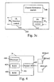
- Fig. 3c is a diagram representing the architecture of a channel interface according to a third mode of realisation of the first telecommunication device.
- the channel interface 205 comprises a channel estimation module 340.
- the channel interface 205 comprises an downlink direction control module 345 which controls the spatial direction of the signals received from the second telecommunication device 10.
- the downlink direction control module 345 performs a downlink beamforming for each signal s 1 (p),..., s N (p).
- MMSE Minimum Mean Squared Error
- the channel estimation module 340 measures the downlink channel quality for each signal s 1 (p),..., s N (p).
- the downlink channel quality is the Signal to Interference plus Noise Ratio ⁇ 1 to ⁇ N determined respectively for each signal s 1 ( p ) to s N ( p ) .
- the channel interface 205 comprises an uplink direction control module 350 which controls the spatial direction of the signals transferred to the second telecommunication device 10 by M k times duplicating the signals and weighting the duplicated signals by coefficients in order to perform beamforming, i.e. controls the spatial direction of the transmitted signals.
- an uplink direction control module 350 which controls the spatial direction of the signals transferred to the second telecommunication device 10 by M k times duplicating the signals and weighting the duplicated signals by coefficients in order to perform beamforming, i.e. controls the spatial direction of the transmitted signals.
- Fig. 4 is a diagram representing the architecture of the second telecommunication device according to the present invention.
- the second telecommunication device 10 has, for example, an architecture based on components connected together by a bus 401 and a processor 400 controlled by programs related to the algorithm as disclosed in the Figs. 5 to 8 .
- the second telecommunication device 10 is, in a variant, implemented under the form of one or several dedicated integrated circuits which execute the same operations as the one executed by the processor 400 as disclosed hereinafter.
- the bus 401 links the processor 400 to a read only memory ROM 402, a random access memory RAM 403 and a channel interface 405.
- the read only memory ROM 402 contains instructions of the programs related to the algorithm as disclosed in the Figs. 5 to 8 which are transferred, when the second telecommunication 10 is powered onto the random access memory RAM 403.
- the RAM memory 403 contains registers intended to receive variables, and the instructions of the programs related to the algorithm as disclosed in the Figs. 5 to 8 .
- the processor 400 determines, for each first telecommunication device 20 k , the number of information representative of the quality of the signals transferred between the first and second telecommunication devices each first telecommunication device 20 k has to report as a channel state information
- the processor 400 is able to determine, for each first telecommunication device 20 1 to 20 K , from the channel state information transferred by each first telecommunication device 20 1 to 20 K , the modulation and coding scheme to be used by each first telecommunication device 20 k for receiving groups of data.
- the processor 400 is able to determine to which first telecommunication device 20, signals representative of a group of data have to be sent according to the channel state information transferred by the first telecommunication devices 20.
- the processor 400 determines for each first telecommunication device 20 1 to 20 K , from the channel state information transferred by each first telecommunication device 20 k , the modulation and coding scheme to be used by each first telecommunication device 20 k for transferring groups of data or pilot signals and/or determines which first telecommunication device 20 has to transfer signals representative of a group of data to the second telecommunication devices 10.
- the channel interface 405 comprises a downlink direction control module, not shown in the Fig. 4 , which controls the spatial direction of the signals transferred to each first telecommunication devices 20 1 to 20 K by N times duplicating the signals and weighting the duplicated signals by coefficients in order to perform beamforming, i.e. controls the spatial direction of the transmitted signals.
- a downlink direction control module not shown in the Fig. 4 , which controls the spatial direction of the signals transferred to each first telecommunication devices 20 1 to 20 K by N times duplicating the signals and weighting the duplicated signals by coefficients in order to perform beamforming, i.e. controls the spatial direction of the transmitted signals.
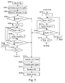
- Fig. 5 is an algorithm executed by the second telecommunication device according to a first mode of realisation of the second telecommunication device.
- the present algorithm is executed each time a new first telecommunication device 20 is detected by the second telecommunication device 10 and/or periodically.
- the processor 400 of the second telecommunication device 10 receives from each first telecommunication device 20 1 to 20 K , through the uplink channel, information representative of the number of antennas each first telecommunication device 20 1 to 20 K has. At the same step, the processor 400 determines the number K of first telecommunication devices 20.
- the processor 400 memorises the number of antennas M 1 to M K and K in the RAM memory 403.
- the processor 400 initializes the value of the variables m 0 (1) to m 0 (K) to one.
- the processor 400 selects a variable k' with 1 ⁇ k' ⁇ K .
- the processor 400 selects randomly k' .
- the processor 400 checks whether or not the sum of the variables m 0 (1) to m 0 ( K ) is lower than the total number C of available pilot signals, the second telecommunication device 10 can use.
- the processor 400 sets the variable k to the value of the variable k '.
- the processor 400 checks if the variable m 0 ( k ) is equal to the number of antennas M K of the first telecommunication device 20 k .
- step S507 If the variable m 0 ( k ) is equal to the number of antennas M K of the first telecommunication device 20 k , the processor 400 moves to step S507.
- step S506 If the variable m 0 ( k ) is not equal to the number of antennas M K of the first telecommunication device 20 k , the processor 400 moves to step S506.
- step S506 the processor 400 increments the value of variable m 0 ( k ) , as example of one and moves to step S507.
- the processor 400 checks whether or not the sum of the variables m 0 (1) to m 0 ( K ) is lower than the total number C of available pilot signals, the second telecommunication device 10 has.
- step S508 If the sum of the variables m 0 (1) to m 0 (K) is lower than the total number C of available pilot signals, the processor 400 moves to step S508.
- the processor 400 checks if the value of k is equal to K.
- step S509 increments the value of variable k by one and returns to step S505.
- the processor 400 set the value of the variable k to one.
- the processor 400 checks if the variable m 0 (k) is equal to the number of antennas M K of the first telecommunication device 20 k .
- step S518 If the variable m 0 (k) is equal to the number of antennas M K of the first telecommunication device 20 k , the processor 400 moves to step S518.
- step S517 If the variable m 0 (k) is not equal to the number of antennas M K of the first telecommunication device 20 k , the processor 400 moves to step S517.
- step S517 the processor 400 increments the value of variable m 0 (k) , as example of one and moves to step S518.
- the processor 400 checks whether or not the sum of the variables m 0 (1) to m 0 (K) is lower than the total number C of available pilot signals, the second telecommunication device 10 has.
- the processor 400 checks if the value of k is equal to k '-1.
- step S520 increments the value of variable k by one and returns to step S516.
- step S502 If the value of k is equal to k '-1, the processor 400 returns to step S502.
- the variable m 0 ( k ) is the number of information representative of the quality of the signals transferred between the first and second telecommunication devices that the first telecommunication device 20 k has to report as a channel state information.
- the processor 400 allocates then to each at least a part of the first telecommunication device 20 k , a number of pilot signals which is equal to m 0 ( k ) .
- the processor 400 detects the reception of the channel state information transferred by at least a part of the first telecommunication devices 20.
- the channel state information is received under the form of pilot signals or under the form of bit information.
- the processor 400 determines also the modulation and coding scheme to be used by each first telecommunication device 20 k for receiving groups of data or for transferring groups of data.
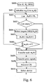
- Fig. 6 is an algorithm executed by the second telecommunication device according to a second mode of realisation of the second telecommunication device.
- the present algorithm is executed each time a new first telecommunication device 20 is detected by the second telecommunication device 10 and/or periodically.
- the processor 400 of the second telecommunication device 10 receives from each first telecommunication device 20 l to 20 K , through the uplink channel, information representative of the number of antennas each first telecommunication device 20 1 to 20 K has and their respective requirement DR(k) in term of data rate.
- the processor 400 determines the number K of first telecommunication devices 20.
- the processor 400 memorises the number of antennas M 1 to M K , the requirements DR(1) to DR ( K ) in term of data rate and K in the RAM memory 403.
- the processor 400 initializes the value of the variables m 0 (1) to m 0 (K) to one.
- the processor 400 forms a list which comprises the variables m 0 ( k ) which are lower than the corresponding M k .
- the processor 400 checks if the formed list is empty or not.
- the processor 400 selects in the list, the variable m 0 ( k ) which corresponds to the largest value of DR(k) / m 0 ( k ).
- step S605 the processor 400 increments the value of the selected variable m 0 ( k ) , as example of one and moves to step S606.
- the processor 400 checks whether or not the sum of the variables m 0 (1) to m 0 ( K ) is lower than the total number C of available pilot signals, the second telecommunication device 10 can use, where K ⁇ C .
- step S607 If the sum of the variables m 0 (1) to m 0 ( K ) is equal to the total number C of available pilot signals, the processor 400 moves to step S607.
- the variable m 0 ( k ) is the number of information representative of the quality of the signals transferred between the first and second telecommunication devices that the first telecommunication device 20 k has to report as a channel state information.
- the processor 400 allocates then to each at least a part of the first telecommunication device 20 k , a number of pilot signals which is equal to m 0 ( k ) .
- the processor 400 detects the reception of the channel state information transferred by at least a part of the first telecommunication devices 20.
- the channel state information is received under the form of pilot signals or under the form of bit information comprised in a group of data.
- the processor 400 determines also the modulation and coding scheme to be used by each first telecommunication device 20 k for receiving groups of data or for transferring groups of data.
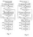
- Fig. 7 is an algorithm executed by the second telecommunication device according to a third mode of realisation of the second telecommunication device.
- the present algorithm is executed each time a new first telecommunication device 20 is detected by the second telecommunication device 10 and/or periodically.
- the processor 400 of the second telecommunication device 10 receives from each first telecommunication device 20 1 to 20 K , through the uplink channel, information representative of the number of antennas each first telecommunication device 20 1 to 20 K has and their respective requirement DT ( k ) in term of response delay. At the same step, the processor 400 determines the number K of first telecommunication devices 20.
- the processor 400 memorises the number of antennas M 1 to M K , the requirements DT(1) to DT(K) in term of response delay and K in the RAM memory 403.
- the processor 400 initializes the value of the variables m 0 (1) to m 0 ( K ) to one.
- the processor 400 forms a list which comprises the variables m 0 ( k ) which are lower than the corresponding M k .
- the processor 400 checks if the formed list is empty or not.
- step S707 If the list is empty, the processor 400 moves to step S707.
- the processor 400 selects in the list, the variable m 0 (k) which corresponds to the smallest value of DT(k) * m 0 (k).
- step S705 the processor 400 increments the value of the selected variable m 0 ( k ) , as example of one and moves to step S706.
- the processor 400 checks whether or not the sum of the variables m 0 (1) to m 0 (K) is lower than the total number C of available pilot signals, the second telecommunication device 10 can use, where K ⁇ C .
- step S707 If the sum of the variables m 0 (1) to m 0 (K) is equal to the total number C of available pilot signals, the processor 400 moves to step S707.
- step S702 If the sum of the variables m 0 (1) to m 0 (K) is lower than the total number C of available pilot signals, the processor 400 moves to step S702.
- the variable m 0 (k) is the number of information representative of the quality of the signals transferred between the first and second telecommunication devices that the first telecommunication device 20 k has to report as a channel state information.
- the processor 400 allocates then to each at least a part of the first telecommunication device 20 k , a number of pilot signals which is equal to m 0 (k) .
- the processor 400 detects the reception of the channel state information transferred by at least a part of the first telecommunication devices 20.
- the channel state information is received under the form of pilot signals or under the form of bit information comprised in a group of data.
- the processor 400 determines also the modulation and coding scheme to be used by each first telecommunication device 20 k for receiving groups of data or for transferring groups of data.
- Fig. 8 is an algorithm executed by the second telecommunication device according to a fourth mode of realisation of the second telecommunication device.
- the present algorithm is executed each time a new first telecommunication device 20 is detected by the second telecommunication device 10 and/or periodically.
- the processor 400 of the second telecommunication device 10 receives from each first telecommunication device 20 1 to 20 K , through the uplink channel, information representative of the number of antennas each first telecommunication device 20 1 to 20 K has. At the same step, the processor 400 determines the number K of first telecommunication devices 20.
- the processor 400 memorises the number of antennas M 1 to M K and K in the RAM memory 403.
- the processor 400 initializes the value of the variables m 0 (1) to m 0 ( K ) to one.
- the processor 400 forms a list which comprises the variables m 0 (k) which are lower than the corresponding M k .
- the processor 400 checks if the formed list is empty or not.
- the processor 400 selects in the list, the variable m 0 ( k ) which corresponds to the largest value of M k / m 0 ( k ) .
- step S805 the processor 400 increments the value of the selected variable m 0 (k) , as example of one and moves to step S806.
- the processor 400 checks whether or not the sum of the variables m 0 (1) to m 0 ( K ) is lower than the total number C of available pilot signals, the second telecommunication device 10 can use, where K ⁇ C .
- step S807 If the sum of the variables m 0 (1) to m 0 ( K ) is equal to the total number C of available pilot signals, the processor 400 moves to step S807.
- step S802 If the sum of the variables m 0 (1) to m 0 ( K ) is lower than the total number C of available pilot signals, the processor 400 moves to step S802.
- the variable m 0 ( k ) is the number of information representative of the quality of the signals transferred between the first and second telecommunication devices that the first telecommunication device 20 k has to report as a channel state information.
- the processor 400 allocates then to each at least a part of the first telecommunication device 20 k , a number of pilot signals which is equal to m 0 ( k ) .
- the processor 400 detects the reception of the channel state information transferred by at least a part of the first telecommunication devices 20.
- the channel state information is received under the form of pilot signals or under the form of bit information comprised in a group of data.
- the processor 400 determines also the modulation and coding scheme to be used by each first telecommunication device 20 k for receiving groups of data or for transferring groups of data.
- first, second, third and fourth modes of realisation of the second telecommunication device are in a variant combined in order to determine m 0 (k) according to the number of first telecommunication devices 20 and/or the number of antennas the first telecommunication devices 20 have and/or according to the requirements in term of data rate and or response delay.
- the first telecommunication device By changing for each first telecommunication device, the number of information representative of the quality of the signals transferred between the first and second telecommunication devices the first telecommunication device has to report as a channel state information according to the number of first telecommunication devices 20 and/or the number of antennas the first telecommunication devices 20 have and/or according to the requirements in term of data rate and or response delay for the channel station information reporting, the available resources of the wireless telecommunication network are efficiently used in any environment.
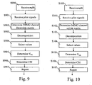
- Fig. 9 is an algorithm executed by the first telecommunication device according to the first mode of realisation of the first telecommunication device.
- the present algorithm is executed by each first telecommunication device 20 1 to 20 K , it will be disclosed when it is executed by the first telecommunication device 20 k .
- the processor 200 of, as example, the first telecommunication device 20 k detects the reception through the channel interface 205 of a group of data which comprises the variable m 0 ( k ) which is the number of information representative of the quality of the signals transferred between the first and second telecommunication devices that the first telecommunication device 20 k has to report as a channel state information.
- variable m 0 ( k ) is either determined according to the first or second or third or fourth modes of realisation of the second telecommunication device.
- the MIMO channel matrix estimation module 305 estimates the matrix H DL,K from the received pilot signals.
- the processor 200 selects the m 0 (k) largest singular-values. As example, if the first telecommunication device 20k has three antennas, and the received m 0 (k) equals to two, only the two largest singular-values are selected.
- the m 0 ( k ) singular-values are selected from the downlink MIMO channel matrix H DL,k between the second telecommunication device 10 and the first telecommunication device 20 k .
- the processor 200 determines a downlink linear transform matrix V DL .
- V DL ⁇ e 1 ⁇ H DL , k * ⁇ H DL , k T ⁇ , ... e m ⁇ 0 k ⁇ H DL , k * ⁇ H DL , k T ⁇ ⁇ , where e m ⁇ . ⁇ denotes the eigenvector of ⁇ . ⁇ corresponding to the m -th largest eigenvalue.
- H DL , k T H UL , k
- the first telecommunication device 20 k sends m 0 ( k ) pilot signals r '( p ) multiplied by the uplink linear transform matrix V DL .
- the processor 200 transfers the determined matrix V DL to the downlink linear transform module 310 which uses the determined matrix V DL for executing a linear transformation of the signal vector x k ( p ) using the m 0 ( k )* M k matrix V DL T .
- the processor 200 determines the channel state information on the downlink channel considering x '( p ) .
- the channel state information is the m 0 (k) * N virtual downlink MIMO channel matrix H ⁇ DL,k .
- the processor 200 commands the transfer, to the second telecommunication device 10, of the determined channel state information through the uplink channel.
- the channel state information is reported by transferring m 0 (k) pilot signals which are multiplied by the downlink linear transform matrix V DL .
- the channel state information can also be reported under the form of information bits.
- the processor 200 returns then to step S900.
- Fig. 10 is an algorithm executed by the first telecommunication device according to the second mode of realisation of the first telecommunication device.
- the present algorithm is executed by each first telecommunication device 20 l to 20 K , it will be disclosed when it is executed by the first telecommunication device 20 k .
- the processor 200 of, as example, the first telecommunication device 20 k detects the reception through the channel interface 205 of a group of data which comprises the variable m 0 ( k ) which is the number of information representative of the quality of the signals transferred between the first and second telecommunication devices that the first telecommunication device 20 k has to report as a channel state information.
- variable m 0 ( k ) is either determined according to the first or second or third or fourth modes of realisation of the second telecommunication device.
- the MIMO channel matrix estimation module 320 estimates the uplink channel matrix H UL,k .
- H UL , k H DL , k T as the channel responses between the uplink and downlink channels of the telecommunication network 15 are reciprocal.
- U U [ u U 1 ,... u UN ] is the N*N unitary matrix
- Q U [ q U 1 ,...q UMk ] is the M k * M k unitary matrix
- the processor 200 selects the m 0 ( k ) largest singular-values.
- the m 0 ( k ) singular-values are selected from the uplink MIMO channel matrix H UL,k between the first telecommunication device 20 k and the second telecommunication device 10.
- step S105 the processor 200 determines a linear transform matrix V UL .
- V UL ⁇ e 1 ⁇ H UL , k H ⁇ H UL , k ⁇ , ... e m ⁇ 0 k ⁇ H UL , k H ⁇ H UL , k ⁇ ⁇ , where e m ⁇ . ⁇ denotes the eigenvector of ⁇ . ⁇ corresponding to the m -th largest eigenvalue.
- the processor 200 commands the transfer, to the second telecommunication device 10, of the determined channel state information through the uplink channel.
- the channel state information is reported by transferring m 0 ( k ) pilot signals composed of p 0 symbols r '(1),... r '( p 0 ) to the second telecommunication device 10 through the channel interface 205.
- the processor 200 returns then to step S100.
- Fig. 11 is an algorithm executed by the first telecommunication device according to the third mode of realisation of the first telecommunication device.
- the present algorithm is executed by each first telecommunication device 20 1 to 20 K , it will be disclosed when it is executed by the first telecommunication device 20 k .
- the processor 200 of, as example, the first telecommunication device 20 k detects the reception through the channel interface 205 of a group of data which comprises the variable m 0 ( k ) is the number of information representative of the quality of the signals transferred between the first and second telecommunication devices that the first telecommunication device 20 k has to report as a channel state information.
- variable m 0 ( k ) is either determined according to the first or second or third or fourth modes of realisation of the second telecommunication device.
- the first telecommunication device 20k receives pilot signals through the channel interface 205.
- the downlink direction control module 345 performs a downlink beamforming for each signal s 1 (p),..., s N (p) .
- the processor 200 commands the channel estimation module 340 of the channel interface 205 to transfer a downlink channel quality estimated for each signal s 1 (p ),..., s N (p) .
- the channel estimation module 340 measures the downlink channel quality for each signal s 1 (p),..., s N (p) .
- the downlink channel quality is the Signal to Interference plus Noise Ratio ⁇ 1 to ⁇ N determined at the outputs v k ⁇ 1 T ⁇ x k p , ... , v kN T ⁇ x k p respectively for each signal s 1 ( p ) to s N ( p ) .
- the processor 200 selects the m 0 ( k ) largest Signal to Interference plus Noise Ratio among the N Signal to Interference plus Noise Ratio ⁇ 1 to ⁇ N .
- the processor 200 commands the transfer, to the second telecommunication device 10, of the selected m 0 ( k ) largest Signal to Interference plus Noise Ratio as a channel state information through the uplink channel.
- Fig. 12 is an example of the channel state information transferred by a first telecommunication device according to the third mode of realisation of the first telecommunication device.
- the channel state information is transferred in a group of data.
- the first telecommunication device 20 k determines the propagation gains between the antennas of the first and second telecommunication devices as it has already been described.
- the first telecommunication device 20 k forms, for each of the first telecommunication device's antenna, a group propagation gains and determines among the groups, the ones which have the highest norm.
- the first telecommunication device selects among the determined propagation gains the group or groups which has or have the highest m 0 (k) norm, as the subset of the determined propagation gains.
- the first telecommunication device 20 k selects m 0 (k) antennas among its M k antennas which have the m 0 (k) largest values ⁇ h m ⁇ among ⁇ h 1 ⁇ ,..., ⁇ h Mk ⁇ .
- V DL 1 0 0 0 0 1 0 0
- V DL T ⁇ H DL , k h 1 h 3 .
- the virtual MIMO downlink channel comprises only the highest propagation gains ⁇ h 1 ⁇ and ⁇ h 3 ⁇ .
Abstract
Description
- The present invention relates generally to telecommunication systems and in particular, to methods and devices for controlling channel state information transferred by a first telecommunication device to a second telecommunication device.
- Recently, efficient transmission schemes in space and frequency domains have been investigated to meet the growing demand for high data rate wireless telecommunications. In the space domain, Multi-Input Multi-Output (MIMO) systems using multiple antennas at both transmitter and receiver sides have gained attention to exploit the potential increase of the spectral efficiency.
- In some transmission schemes using MIMO systems, the telecommunication device which transmits data streams has some knowledge of the channel conditions which exist between itself and the telecommunication devices to which the data streams are transferred. The telecommunication device directs the signals transferred to a telecommunication device according to the channel conditions, and then improves the overall performances of the system.
- Practically, when the channels responses between uplink and downlink channels are reciprocal, e.g. in Time Division Multiplex systems, the channel conditions are obtained according to the following method : a telecommunication device like a base station transfers pilot signals to another telecommunication device like a mobile terminal, the mobile terminal receives the pilot signals, determines the channel responses from the received pilot signals, as example under the form of a channel matrix which is representative of the channel conditions, and uses the determined matrix in order to direct the signals which have to be transferred to the base station which has sent the pilot signals.
- The coefficients of the determined channel matrix are the complex propagation gains between the antennas of the base station and the antennas of the mobile terminal.
- Some of the complex propagation gains reflect poor channel propagation conditions which exist between some antennas of the base station and the mobile terminal.
- If an important number of mobile terminals report all coefficients of the determined channel matrix to the base station, the transfer of these coefficients requires an important part of the available bandwidth of the overall wireless telecommunication network and the base station needs to have important calculation means in order to treat all these coefficient.
- Other channel conditions measurements can also be determined. The channel conditions are as example the Signal to Interference plus Noise Ratio measured by the mobile terminal.
- If an important number of mobile terminals report all the Signal to Interference plus Noise Ratio, the transfer of these data requires an important part of the available bandwidth of the overall wireless telecommunication network and the base station needs to have important calculation means in order to treat all these coefficient.
-
Patent application US 2005/181739 teaches an adaptive MIMO system in which one of a full feedback mode and a limited feedback mode is selected depending on the expected receiver performance. Full feedback involves reporting of the coefficients of the MIMO channel from the mobile to the base station, while for limited feedback only the channel's signal-to-interference ratio SINR is reported back. The decision as to which mode to use is based for instance on the measured SINR at the mobile, its speed, its number of receive antennas and its supportable data rate. - Application
WO 2004/073200 discloses an OFDM system in which the uplink reporting of channel state information (CSI) is activated or deactivated according to a corresponding flag signalled from the base station on the downlink. - Both applications seek to solve the technical problem of enabling the reporting of the channel conditions without requiring an important part of the available bandwidth of the overall wireless telecommunications network.
- The aim of the present invention is to propose methods and devices which provide an alternative solution for this problem.
- To that end, the present invention concerns a method for controlling channel state information transferred by a first telecommunication device to a second telecommunication device, the first telecommunication device determining information representative of the quality of the signals transferred between the first and second telecommunication devices, characterised in that the method comprises the steps executed by the second telecommunication device of :
- determining a number of information representative of the quality of the signals transferred between the first and second telecommunication devices the first telecommunication device has to report as a channel state information,
- transferring the determined number to the first telecommunication device.
- The present invention concerns also a device for controlling channel state information transferred by a first telecommunication device to a second telecommunication device, the first telecommunication device determining information representative of the quality of the signals transferred between the first and second telecommunication devices, characterised in that the device for controlling is included in the second telecommunication device and comprises :
- means for determining a number of information representative of the quality of the signals transferred between the first and second telecommunication devices the first telecommunication device has to report as a channel state information,
- means for transferring the determined number to the first telecommunication device.
- Thus, the second telecommunication device is able to control the quantity of information representative of the quality of the signals transferred between the first and second telecommunication devices.
- According to a particular feature, the number of information representative of the quality of the signals transferred between the first and second telecommunication devices the first telecommunication device has to report is lower than the number of the determined information representative of the quality of the signals transferred between the first and second telecommunication devices.
- Thus, the part of the available bandwidth of the overall wireless telecommunication network used for the receiving the channel state information is reduced.
- According to a particular feature, the second telecommunication device allocates to the first telecommunication device a number of pilot signals which is equal to the determined number.
- Thus, the available pilot signals are used efficiently.
- According to a particular feature, the second telecommunication device receives the channel state information from the first telecommunication device and controls the transfer of the signals representative of at least a group of data between the first and the second telecommunication devices according to received the channel state information.
- Thus, it is possible to allocate the resources of the network in an efficient way.
- According to a particular feature, the second telecommunication device determines the number of first telecommunication devices which are linked to the second telecommunication device.
- A first telecommunication device is linked to the second telecommunication device when it can transfer signals to the second telecommunication device and receive signals from the second telecommunication device.
- According to a particular feature, the number of information representative of the quality of the signals transferred between the first and second telecommunication devices the first telecommunication device has to report as a channel state information is determined according to the number of first telecommunication devices which are linked to the second telecommunication device.
- Thus, the second telecommunication device allocates the resources of the network among the first telecommunication fairly.
- According to a particular feature, the second telecommunication device receives the number of antennas each first telecommunication device comprises and determines the number of information representative of the quality of the signals transferred between the first and second telecommunication devices each first telecommunication device has to report as a channel state information according to the number of antennas the first telecommunication device comprises.
- Thus, the second telecommunication device allocates the resources of the network among the first telecommunication according to their communication capabilities.
- According to a particular feature, the second telecommunication device receives from each first telecommunication device their respective requirement in term of data rate and determines the number of information representative of the quality of the signals transferred between the first and second telecommunication devices each first telecommunication device has to report as a channel state information according to the requirements in term of data rate.
- Thus, the second telecommunication device allocates the resources of the network among the first telecommunication according to their communication needs.
- According to a particular feature, the second telecommunication device receives from each first telecommunication device, their respective requirement in term of response delay and the number of information representative of the quality of the signals transferred between the first and second telecommunication devices each first telecommunication device has to report as a channel state information is determined according to the requirements in term of response delay.
- Thus, the second telecommunication device allocates the resources of the network among the first telecommunication according to their communication needs.
- According to still another aspect, the present invention concerns a method for transferring, by a first telecommunication device, channel state information to a second telecommunication device, the first telecommunication device determining information representative of the quality of the signals transferred between the first and second telecommunication devices, characterised in that the method comprises the steps executed by the first telecommunication device of :
- receiving from the second telecommunication device a number of information representative of the quality of the signals transferred between the first and second telecommunication devices the first telecommunication device has to report as a channel state information,
- determining a channel state information which comprises the received number of information representative of the quality of the signals transferred between the first and second telecommunication devices,
- transferring the channel state information to the second telecommunication device.
- The present invention concerns also a first telecommunication device which transfers channel state information to a second telecommunication device, the first telecommunication device determining information representative of the quality of the signals transferred between the first and second telecommunication devices, characterised in that the first telecommunication device comprises :
- means for receiving from the second telecommunication device a number of information representative of the quality of the signals transferred between the first and second telecommunication devices the first telecommunication device has to report as a channel state information,
- means for determining a channel state information which comprises the received number of information representative of the quality of the signals transferred between the first and second telecommunication devices,
- means for transferring the channel state information to the second telecommunication device.
- Thus, the quantity of information representative of the quality of the signals transferred between the first and second telecommunication devices is reduced.
- According to a particular feature, the first telecommunication device comprises antennas and the second telecommunication device which comprises antennas and in that the quality of the signals transferred between the first and second telecommunication devices is the propagation gain between one antenna of the first telecommunication devices and one antenna of the second telecommunication device.
- Thus, the second telecommunication device is informed about the propagation gains which are determined by the first telecommunication device.
- According to a particular feature, the propagations gains are coefficients of a downlink channel matrix and the measured information representative of the quality of the signals transferred between the first and second telecommunication devices comprised in the channel state information are determined by executing a singular value decomposition of the downlink channel matrix.
- Thus, the second telecommunication device is informed about the propagation gains which are determined by the first telecommunication device in the downlink channel.
- According to a particular feature, the propagations gains are coefficients of an uplink channel matrix and the determined information representative of the quality of the signals transferred between the first and second telecommunication devices comprised in the channel state information are determined by executing a singular value decomposition of the uplink channel matrix.
- Thus, the second telecommunication device is informed about the propagation gains which are determined by the first telecommunication device in the uplink channel.
- According to still another aspect, the present invention concerns computer programs which can be directly loaded into a programmable device, comprising instructions or portions of code for implementing the steps of the methods according to the invention, when said computer programs are executed on said programmable device.
- Since the features and advantages relating to the computer programs are the same as those set out above related to the methods and devices according to the invention, they will not be repeated here.
- According to still another aspect, the present invention concerns a signal transferred to a second telecommunication device from a first telecommunication device, characterised in that the signal comprises a number of information representative of the quality of the signals transferred between the first and second telecommunication devices the second telecommunication device has to report as a channel state information to the first telecommunication device.
- Since the features and advantages relating to the signal are the same as those set out above related to the methods and devices according to the invention, they will not be repeated here.
- The characteristics of the invention will emerge more clearly from a reading of the following description of an example embodiment, the said description being produced with reference to the accompanying drawings, among which :
-
Fig. 1 is a diagram representing the architecture of the wireless network according to the present invention ; -
Fig. 2 is a diagram representing the architecture of a first telecommunication device according to the present invention; -
Fig. 3a is a diagram representing the architecture of a channel interface according to a first mode of realisation of the first telecommunication device; -
Fig. 3b is a diagram representing the architecture of a channel interface according to a second mode of realisation of the first telecommunication device; -
Fig. 3c is a diagram representing the architecture of a channel interface according to a third mode of realisation of the first telecommunication device; -
Fig. 4 is a diagram representing the architecture of the second telecommunication device according to the present invention; -
Fig. 5 is an algorithm executed by the second telecommunication device according to a first mode of realisation of the second telecommunication device; -
Fig. 6 is an algorithm executed by the second telecommunication device according to a second mode of realisation of the second telecommunication device; -
Fig. 7 is an algorithm executed by the second telecommunication device according to a third mode of realisation of the second telecommunication device; -
Fig. 8 is an algorithm executed by the second telecommunication device according to a fourth mode of realisation of the second telecommunication device; -
Fig. 9 is an algorithm executed by the first telecommunication device according to the first mode of realisation of the first telecommunication device; -
Fig. 10 is an algorithm executed by the first telecommunication device according to the second mode of realisation of the first telecommunication device; -
Fig. 11 is an algorithm executed by the first telecommunication device according to the third mode of realisation of the first telecommunication device; -
Fig. 12 is an example of the channel state information transferred by a first telecommunication device according to the third mode of realisation of the first telecommunication device. -
Fig. 1 is a diagram representing the architecture of the wireless network according to present invention. - In the wireless network of the
Fig. 1 , at least one and preferably pluralfirst telecommunication devices wireless network 15 to asecond telecommunication device 10 using an uplink and a downlink channel. - Preferably, and in a non limitative way, the
second telecommunication device 10 is a base station or a node of thewireless network 15. Thefirst telecommunication devices 20l to 20K are terminals like mobile phones, personal digital assistants, or personal computers. - The
telecommunication network 15 is a wireless telecommunication system which uses Time Division Duplexing scheme (TDD) or Frequency Division Duplexing scheme (FDD). - In TDD scheme, the signals transferred in uplink and downlink channels are duplexed in different time periods in the same frequency band. The signals transferred within the
wireless network 15 share the same frequency spectrum. The channel responses between the uplink and downlink channels of thetelecommunication network 15 are reciprocal. - Reciprocal means that if the downlink channel conditions are represented by a downlink matrix, the uplink channel conditions can be expressed by an uplink matrix which is the transpose of the downlink matrix.
- In FDD scheme, the signals transferred in uplink and downlink channels are duplexed in different frequency bands. The spectrum is divided into different frequency bands and the uplink and downlink signals are transmitted simultaneously. The channel responses between the uplink and downlink channels of the
telecommunication network 15 are not perfectly reciprocal. - The
second telecommunication device 10 transfers simultaneously signals representatives of at most N groups of data or pilot signals to thefirst telecommunication devices 201 to 20K through the downlink channel and thefirst telecommunication devices 201 to 20K transfer signals to thesecond telecommunication device 10 through the uplink channel. - The signals transferred by the
first telecommunication devices 201 to 20K are signals representatives of a group of data or pilot signals. - A group of data is as example a frame constituted at least by a header field and a payload field which comprises classical data like data related to a phone call, or a video transfer and so on.
- Pilot signals are predetermined sequences of symbols known by the telecommunication devices. Pilot signals are, as example and in a non limitative way, Walsh Hadamard sequences.
- According to the first mode of realisation of the
first telecommunication device 20, the pilot signals transferred by thefirst telecommunication devices 201 to 20K are multiplied by a downlink linear transform. The transferred pilot signals comprise then channel state information. - According to the second mode of realisation of the
first telecommunication device 20, the pilot signals transferred by thefirst telecommunication devices 201 to 20K are multiplied by an uplink linear transform. The transferred pilot signals comprise then channel state information. - According to the third mode of realisation of the
first telecommunication device 20, the channel state information is transferred into the form of bit information. - The
second telecommunication device 10 has N antennas noted BSAnt1 to BSAntN. Thesecond telecommunication device 10 preferably controls the spatial direction of the signals transferred to eachfirst telecommunication devices 201 to 20K according to the channel state information transferred by eachfirst telecommunication devices 20 as it will be disclosed hereinafter. - More precisely, when the
second telecommunication device 10 transmits signals representatives of a group of data to a givenfirst telecommunication device 20k through the downlink channel, the signals are at most N times duplicated in order to perform beamforming, i.e. controls the spatial direction of the transmitted signals. - The ellipse noted BF1 in the
Fig. 1 shows the pattern of the radiated signals by the antennas BSAnt1 to BSAntN which are transferred to thefirst telecommunication device 201 by thesecond telecommunication device 10. - The ellipse noted BFK in the
Fig. 1 shows the pattern of the radiated signals by the antennas BSAnt1 to BSAntN which are transferred to thefirst telecommunication device 20K by thesecond telecommunication device 10. - The
first telecommunication devices 201 to 20K have Mk antennas noted respectively MS1Ant1 to MS1AntM1 and MSKAnt1 to MSKAntMk. It has to be noted here that the number Mk of antennas may vary according to eachfirst telecommunication device 20k with k=1 to K. Eachfirst telecommunication device 201 to 20k controls the spatial direction of the signals transferred to thesecond telecommunication device 10 as it will be disclosed hereinafter. - Each
first telecommunication device 20l to 20k controls the spatial direction of the signals transferred to thesecond telecommunication device 10 by M k times duplicating the signals and weighting the duplicated signals by coefficients in order to perform beamforming, i.e. controls the spatial direction of the transmitted signals. - The ellipse noted
BF 1 in theFig. 1 shows the pattern of the radiated signals by the antennas MS1Ant1 to MS1AntM1 which are transferred by thefirst telecommunication device 201 to thesecond telecommunication device 10. - The ellipse noted BFK in the
Fig. 1 shows the pattern of the radiated signals by the antennas MSKAnt1 to MSKAntMK which are transferred by thefirst telecommunication device 20K to thesecond telecommunication device 10. - According to the third mode of realisation of the
first telecommunication device 20, eachfirst telecommunication device 201 to 20k controls the spatial direction of the signals received from thesecond telecommunication device 10 in order to perform beamforming, i.e. controls the spatial direction of the received signals. - The
second telecommunication device 10 determines, for eachfirst telecommunication device 20k, the number of information representative of the quality of the signal transferred between the first and second telecommunication device eachfirst telecommunication device 20k has to report as a the channel state information between. - Each
first telecommunication device 20k receives from the second telecommunication device 10 a number of information representative of the quality of the signals transferred between the first and second telecommunication devices the first telecommunication device has to report as a channel state information. -
Fig. 2 is a diagram representing the architecture of a first telecommunication device according to the present invention. - The
first telecommunication device 20, as example thefirst telecommunication device 20k, with k comprised between 1 and K, has, for example, an architecture based on components connected together by abus 201 and aprocessor 200 controlled by programs related to the algorithm as disclosed in theFigs. 9 or 10 or11 . - It has to be noted here that the
first telecommunication device 20 is, in a variant, implemented under the form of one or several dedicated integrated circuits which execute the same operations as the one executed by theprocessor 200 as disclosed hereinafter. - The
bus 201 links theprocessor 200 to a read onlymemory ROM 202, a randomaccess memory RAM 203 and achannel interface 205. - The read only
memory ROM 202 contains instructions of the programs related to the algorithm as disclosed in theFigs. 9 or 10 or11 which are transferred, when thefirst telecommunication device 20k is powered on to the randomaccess memory RAM 203. - The
RAM memory 203 contains registers intended to receive variables, and the instructions of the programs related to the algorithm as disclosed in theFigs. 9 or 10 or11 . - The
channel interface 205 enables the transfer and/or of the reception of signals to and/or from thesecond telecommunication device 10. - The
channel interface 205 will be described in detail in reference to theFig. 3a, Fig. 3b andFig. 3c . -
Fig. 3a is a diagram representing the architecture of a channel interface according to a first mode of realisation of the first telecommunication device. - According to the first mode of realisation of the first telecommunication device, the
channel interface 205 comprises a MIMO channelmatrix estimation module 305. - The MIMO channel
matrix estimation module 305 receives the Mk* 1 signals xk (p)=HDL,ks(p)+zk (p) , where, s(p) = [s 1(p),...,sN (p)] T are signals representative of the p-th pilot symbol transferred by thesecond telecommunication device 10, zk (p) is the Mk*1 interference plus noise vector at thefirst telecommunication device 20k and HDL,k is the Mk*N downlink MIMO channel matrix between thesecond telecommunication device 10 andfirst telecommunication device 20k. - The MIMO channel
matrix estimation module 305 estimates the matrix H DL,K . - Each element (m,n) with m=1 to Mk and n=1 to N of the matrix H DL,K represents the complex propagation gain from the n-th antenna of the
second telecommunication device 10 and the m-th of thefirst telecommunication device 20k. - The
channel interface 205 comprises a downlinklinear transform module 310 which comprises means for executing a linear transformation of the signal vector x k (p) using a m 0 * M k matrix
- Then, the linear transform yields the m 0 * 1 output vector :


where

- The dimension of the downlink linear transform matrix

first telecommunication device 20k has to report as a channel state information. - The downlink linear transform matrix

first telecommunication device 20k has good channel conditions at the output x'(p). - The downlink
linear transform module 310 executes a linear transform on the signals received by the first telecommunication device. The downlinklinear transform module 310 executes a linear transform on the m 0 pilot signals transferred by thefirst telecommunication device 20k to thesecond telecommunication device 10 which comprise then a channel state information. - Preferably and in a non limitative way, the
channel interface 205 comprises an uplinkdirection control module 315 which controls the spatial direction of the signals transferred to thesecond telecommunication device 10 by Mk times duplicating the signals and weighting the duplicated signals by coefficients in order to perform beamforming, i.e. controls the spatial direction of the transmitted signals. -
Fig. 3b is a diagram representing the architecture of a channel interface according to a second mode of realisation of the first telecommunication device. - According to the second mode of realisation of the first telecommunication device, the
channel interface 205 comprises a MIMO channelmatrix estimation module 320. - The MIMO channel
matrix estimation module 320 estimates also the matrix HUL,k which is the N*Mk uplink MIMO channel matrix between thefirst telecommunication device 20k and thesecond telecommunication device 10. - Each element (n,m) with m=1 to Mk and n=1 to N of the matrix HUL,k represents the complex propagation gain from the m-th antenna of the
first telecommunication device 20k and the n-th of thesecond telecommunication device 10. - Preferably the matrix HUL,k is equal to HT DL,k where [.] T denotes the transpose of [.].
- The
channel interface 205 comprises an uplinklinear transform module 325 which comprises means for executing a linear transformation of m 0 signals r'(p) = [r'1 (p),..., r' m0 (p)] T into the Mk × 1 signal vector r(p) using the Mk × m 0 linear transformation matrix VUL as r(p) = VULr(p)'. - The dimension of the uplink linear transform matrix VUL is defined according to the number of information representative of the quality of the signals transferred between the first and second telecommunication devices that the
first telecommunication device 20k has to report as a channel state information - As it will be disclosed hereinafter, the uplink linear transform matrix VUL is also defined so that good channel conditions are maintained between the
first telecommunication device 20k and thesecond telecommunication device 10. - The uplink
linear transform module 325 executes a linear transform on the signals representative of groups of data transferred by the first telecommunication device. The uplinklinear transform module 305 executes a linear transform on the m 0 pilot signals transferred by thefirst telecommunication device 20k to thesecond telecommunication device 10 which comprise then a channel state information. - Preferably and in a non limitative way, the
channel interface 205 comprises an uplink direction control module 335 which controls the spatial direction of the signals transferred to thesecond telecommunication device 10 by Mk times duplicating the signals and weighting the duplicated signals by coefficients in order to perform beamforming, i.e. controls the spatial direction of the transmitted signals. -
Fig. 3c is a diagram representing the architecture of a channel interface according to a third mode of realisation of the first telecommunication device. - According to the third mode of realisation of the first telecommunication device, the
channel interface 205 comprises achannel estimation module 340. - The
second telecommunication device 10 transfers N pilot signals s(p) = [s 1 (p),...,sN (p)] T using fixed N transmit beamforming based on the constant N* 1 different weights w 1,..., wN . Thefirst telecommunication device 20k receives a Mk* 1 signal vector xk (p) = HDL,k Ws(p) + zk (p) with W = [w 1,...wN ]. - The
channel interface 205 comprises an downlinkdirection control module 345 which controls the spatial direction of the signals received from thesecond telecommunication device 10. - The downlink
direction control module 345 performs a downlink beamforming for each signal s 1 (p),..., sN(p). - The downlink
direction control module 345 uses N weights ν kn with n=1 to N in order to perform the downlink beamforming. - Preferably, the weight ν kn for the n-th signal is given by a Minimum Mean Squared Error (MMSE) weight ν kn= Φ-1 α n
where
- From the output of the downlink
direction control module 345, thechannel estimation module 340 measures the downlink channel quality for each signal s 1 (p),..., sN(p). Preferably and in a non limitative way, the downlink channel quality is the Signal to Interference plus Noise Ratio γ 1 to γN determined respectively for each signal s 1(p) to sN (p). - Preferably and in a non limitative way, the
channel interface 205 comprises an uplinkdirection control module 350 which controls the spatial direction of the signals transferred to thesecond telecommunication device 10 by Mk times duplicating the signals and weighting the duplicated signals by coefficients in order to perform beamforming, i.e. controls the spatial direction of the transmitted signals. -
Fig. 4 is a diagram representing the architecture of the second telecommunication device according to the present invention. - The
second telecommunication device 10, has, for example, an architecture based on components connected together by abus 401 and aprocessor 400 controlled by programs related to the algorithm as disclosed in theFigs. 5 to 8 . - It has to be noted here that the
second telecommunication device 10 is, in a variant, implemented under the form of one or several dedicated integrated circuits which execute the same operations as the one executed by theprocessor 400 as disclosed hereinafter. - The
bus 401 links theprocessor 400 to a read onlymemory ROM 402, a randomaccess memory RAM 403 and a channel interface 405. - The read only
memory ROM 402 contains instructions of the programs related to the algorithm as disclosed in theFigs. 5 to 8 which are transferred, when thesecond telecommunication 10 is powered onto the randomaccess memory RAM 403. - The
RAM memory 403 contains registers intended to receive variables, and the instructions of the programs related to the algorithm as disclosed in theFigs. 5 to 8 . - According to the present invention, the
processor 400 determines, for eachfirst telecommunication device 20k, the number of information representative of the quality of the signals transferred between the first and second telecommunication devices eachfirst telecommunication device 20k has to report as a channel state information - According to the present invention, the
processor 400 is able to determine, for eachfirst telecommunication device 201 to 20K, from the channel state information transferred by eachfirst telecommunication device 201 to 20K, the modulation and coding scheme to be used by eachfirst telecommunication device 20k for receiving groups of data. Theprocessor 400 is able to determine to whichfirst telecommunication device 20, signals representative of a group of data have to be sent according to the channel state information transferred by thefirst telecommunication devices 20. Theprocessor 400 determines for eachfirst telecommunication device 201 to 20K, from the channel state information transferred by eachfirst telecommunication device 20k, the modulation and coding scheme to be used by eachfirst telecommunication device 20k for transferring groups of data or pilot signals and/or determines whichfirst telecommunication device 20 has to transfer signals representative of a group of data to thesecond telecommunication devices 10. - Preferably and in a non limitative way, the channel interface 405 comprises a downlink direction control module, not shown in the
Fig. 4 , which controls the spatial direction of the signals transferred to eachfirst telecommunication devices 201 to 20K by N times duplicating the signals and weighting the duplicated signals by coefficients in order to perform beamforming, i.e. controls the spatial direction of the transmitted signals. -
Fig. 5 is an algorithm executed by the second telecommunication device according to a first mode of realisation of the second telecommunication device. - The present algorithm is executed each time a new
first telecommunication device 20 is detected by thesecond telecommunication device 10 and/or periodically. - At step S500, the
processor 400 of thesecond telecommunication device 10 receives from eachfirst telecommunication device 201 to 20K, through the uplink channel, information representative of the number of antennas eachfirst telecommunication device 201 to 20K has. At the same step, theprocessor 400 determines the number K offirst telecommunication devices 20. - The
processor 400 memorises the number of antennas M1 to MK and K in theRAM memory 403. - At next step S501, the
processor 400 initializes the value of the variables m 0(1) to m0(K) to one. - At next step S502, the
processor 400 selects a variable k' with 1 ≤ k' ≤ K. Preferably, theprocessor 400 selects randomly k'. - At next step S503, the
processor 400 checks whether or not the sum of the variables m 0 (1) to m 0 (K) is lower than the total number C of available pilot signals, thesecond telecommunication device 10 can use. - It has to be noted here that K ≤ C .
- If the sum of the variables m 0(1) to m 0(K) is equal to the total number C of available pilot signals, the
processor 400 moves to step S525. - If the sum of the variables m 0(1) to m 0(K) is lower than the total number C of available pilot signals, the
processor 400 moves to step S504. - At step S504, the
processor 400 sets the variable k to the value of the variable k'. - At next step S505, the
processor 400 checks if the variable m 0(k) is equal to the number of antennas MK of thefirst telecommunication device 20k. - If the variable m 0(k) is equal to the number of antennas MK of the
first telecommunication device 20k, theprocessor 400 moves to step S507. - If the variable m 0(k) is not equal to the number of antennas MK of the
first telecommunication device 20k, theprocessor 400 moves to step S506. - At step S506, the
processor 400 increments the value of variable m 0(k), as example of one and moves to step S507. - At next step S507, the
processor 400 checks whether or not the sum of the variables m 0(1) to m 0(K) is lower than the total number C of available pilot signals, thesecond telecommunication device 10 has. - If the sum of the variables m 0(1) to m 0 (K) is equal to the total number C of available pilot signals, the
processor 400 moves to step S525. - If the sum of the variables m 0(1) to m 0 (K) is lower than the total number C of available pilot signals, the
processor 400 moves to step S508. - At step S508, the
processor 400 checks if the value of k is equal to K. - If the value of k is not equal to K, the
processor 400 moves to step S509, increments the value of variable k by one and returns to step S505. - If the value of k is equal to K, the
processor 400 moves to step S515. - At step S515, the
processor 400 set the value of the variable k to one. - At next step S515, the
processor 400 checks if the variable m 0 (k) is equal to the number of antennas MK of thefirst telecommunication device 20k. - If the variable m 0 (k) is equal to the number of antennas MK of the
first telecommunication device 20k, theprocessor 400 moves to step S518. - If the variable m 0 (k) is not equal to the number of antennas MK of the
first telecommunication device 20k, theprocessor 400 moves to step S517. - At step S517, the
processor 400 increments the value of variable m 0 (k), as example of one and moves to step S518. - At next step S518, the
processor 400 checks whether or not the sum of the variables m 0 (1) to m 0 (K) is lower than the total number C of available pilot signals, thesecond telecommunication device 10 has. - If the sum of the variables m 0 (1) to m 0 (K) is equal to the total number C of available pilot signals, the
processor 400 moves to step S525. - If the sum of the variables m 0 (1) to m 0 (K) is lower than the total number C of available pilot signals, the
processor 400 moves to step S519. - At step S519, the
processor 400 checks if the value of k is equal to k'-1. - If the value of k is not equal to k'-1, the
processor 400 moves to step S520, increments the value of variable k by one and returns to step S516. - If the value of k is equal to k'-1, the
processor 400 returns to step S502. - At step S525, the
processor 400 commands the transfer to eachfirst telecommunication device 20k with k=1 to K of the corresponding value of the variable m 0(k). - For each
first telecommunication device 20k, the variable m 0(k) is the number of information representative of the quality of the signals transferred between the first and second telecommunication devices that thefirst telecommunication device 20k has to report as a channel state information. - At next step S526, the
processor 400 of thesecond telecommunication device 10 commands the transfer of pilot signals to at least a part of thefirst telecommunication devices 20k, with k=1 to K. - The
processor 400 allocates then to each at least a part of thefirst telecommunication device 20k, a number of pilot signals which is equal to m 0(k). - At next step S527, the
processor 400 detects the reception of the channel state information transferred by at least a part of thefirst telecommunication devices 20. - The channel state information is received under the form of pilot signals or under the form of bit information.
- At next step S528, the
processor 400 determines to whichfirst telecommunication device 20k, with k=1 to K, group of data has to be transferred according to the channel state information received from at least the part of thefirst telecommunication devices 20. Theprocessor 400 determines also the modulation and coding scheme to be used by eachfirst telecommunication device 20k for receiving groups of data or for transferring groups of data. -
Fig. 6 is an algorithm executed by the second telecommunication device according to a second mode of realisation of the second telecommunication device. - The present algorithm is executed each time a new
first telecommunication device 20 is detected by thesecond telecommunication device 10 and/or periodically. - At step S600, the
processor 400 of thesecond telecommunication device 10 receives from eachfirst telecommunication device 20l to 20K, through the uplink channel, information representative of the number of antennas eachfirst telecommunication device 201 to 20K has and their respective requirement DR(k) in term of data rate. At the same step, theprocessor 400 determines the number K offirst telecommunication devices 20. - The
processor 400 memorises the number of antennas M1 to MK, the requirements DR(1) to DR(K) in term of data rate and K in theRAM memory 403. - At next step S601, the
processor 400 initializes the value of the variables m 0 (1) to m0(K) to one. - At next step S602, the
processor 400 forms a list which comprises the variables m 0(k) which are lower than the corresponding Mk . - At next step S603, the
processor 400 checks if the formed list is empty or not. - If the list is empty, the
processor 400 moves to step S607. - If the list is not empty, the
processor 400 moves to step S604. - At step S604, the
processor 400 selects in the list, the variable m 0(k) which corresponds to the largest value of DR(k) / m 0(k). - At next step S605, the
processor 400 increments the value of the selected variable m 0(k), as example of one and moves to step S606. - At next step S606, the
processor 400 checks whether or not the sum of the variables m 0(1) to m 0(K) is lower than the total number C of available pilot signals, thesecond telecommunication device 10 can use, where K ≤ C . - If the sum of the variables m 0(1) to m 0(K) is equal to the total number C of available pilot signals, the
processor 400 moves to step S607. - If the sum of the variables m 0(1) to m 0 (K) is lower than the total number C of available pilot signals, the
processor 400 moves to step S602. - At step S607, the
processor 400 commands the transfer to eachfirst telecommunication device 20k with k=1 to K of the corresponding value of the variable m 0(k). - For each
first telecommunication device 20k, the variable m 0(k) is the number of information representative of the quality of the signals transferred between the first and second telecommunication devices that thefirst telecommunication device 20k has to report as a channel state information. - At next step S608, the
processor 400 of thesecond telecommunication device 10 commands the transfer of pilot signals to at least a part of thefirst telecommunication device 20k, with k= 1 to K. - The
processor 400 allocates then to each at least a part of thefirst telecommunication device 20k, a number of pilot signals which is equal to m 0(k). - At next step S609, the
processor 400 detects the reception of the channel state information transferred by at least a part of thefirst telecommunication devices 20. - The channel state information is received under the form of pilot signals or under the form of bit information comprised in a group of data.
- At next step S610, the
processor 400 determines to whichfirst telecommunication device 20k, with k=1 to K, group of data has to be transferred according to the channel state information received from at least the part of thefirst telecommunication devices 20. - The
processor 400 determines also the modulation and coding scheme to be used by eachfirst telecommunication device 20k for receiving groups of data or for transferring groups of data. -
Fig. 7 is an algorithm executed by the second telecommunication device according to a third mode of realisation of the second telecommunication device. - The present algorithm is executed each time a new
first telecommunication device 20 is detected by thesecond telecommunication device 10 and/or periodically. - At step S700, the
processor 400 of thesecond telecommunication device 10 receives from eachfirst telecommunication device 201 to 20K, through the uplink channel, information representative of the number of antennas eachfirst telecommunication device 201 to 20K has and their respective requirement DT(k) in term of response delay. At the same step, theprocessor 400 determines the number K offirst telecommunication devices 20. - The
processor 400 memorises the number of antennas M1 to MK , the requirements DT(1) to DT(K) in term of response delay and K in theRAM memory 403. - At next step S701, the
processor 400 initializes the value of the variables m 0(1) to m 0(K) to one. - At next step S702, the
processor 400 forms a list which comprises the variables m 0(k) which are lower than the corresponding Mk . - At next step S703, the
processor 400 checks if the formed list is empty or not. - If the list is empty, the
processor 400 moves to step S707. - If the list is not empty, the
processor 400 moves to step S704. - At step S704, the
processor 400 selects in the list, the variable m 0 (k) which corresponds to the smallest value of DT(k) * m 0 (k). - At next step S705, the
processor 400 increments the value of the selected variable m 0(k), as example of one and moves to step S706. - At next step S706, the
processor 400 checks whether or not the sum of the variables m 0(1) to m0(K) is lower than the total number C of available pilot signals, thesecond telecommunication device 10 can use, where K ≤ C. - If the sum of the variables m 0(1) to m0(K) is equal to the total number C of available pilot signals, the
processor 400 moves to step S707. - If the sum of the variables m 0(1) to m0(K) is lower than the total number C of available pilot signals, the
processor 400 moves to step S702. - At step S707, the
processor 400 commands the transfer to eachfirst telecommunication device 20k with k=1 to K of the corresponding value of the variable m0(k) . - For each
first telecommunication device 20k, the variable m 0 (k) is the number of information representative of the quality of the signals transferred between the first and second telecommunication devices that thefirst telecommunication device 20k has to report as a channel state information. - At next step S708, the
processor 400 of thesecond telecommunication device 10 commands the transfer of pilot signals to at least a part of thefirst telecommunication device 20k, with k=1 to K. - The
processor 400 allocates then to each at least a part of thefirst telecommunication device 20k, a number of pilot signals which is equal to m0(k). - At next step S709, the
processor 400 detects the reception of the channel state information transferred by at least a part of thefirst telecommunication devices 20. - The channel state information is received under the form of pilot signals or under the form of bit information comprised in a group of data.
- At next step S710, the
processor 400 determines to whichfirst telecommunication device 20k, with k=1 to K, group of data has to be transferred according to the channel state information received from at least the part of thefirst telecommunication devices 20. - The
processor 400 determines also the modulation and coding scheme to be used by eachfirst telecommunication device 20k for receiving groups of data or for transferring groups of data. -
Fig. 8 is an algorithm executed by the second telecommunication device according to a fourth mode of realisation of the second telecommunication device. - The present algorithm is executed each time a new
first telecommunication device 20 is detected by thesecond telecommunication device 10 and/or periodically. - At step S800, the
processor 400 of thesecond telecommunication device 10 receives from eachfirst telecommunication device 201 to 20K, through the uplink channel, information representative of the number of antennas eachfirst telecommunication device 201 to 20K has. At the same step, theprocessor 400 determines the number K offirst telecommunication devices 20. - The
processor 400 memorises the number of antennas M1 to MK and K in theRAM memory 403. - At next step S801, the
processor 400 initializes the value of the variables m 0(1) to m 0(K) to one. - At next step S802, the
processor 400 forms a list which comprises the variables m 0 (k) which are lower than the corresponding Mk . - At next step S803, the
processor 400 checks if the formed list is empty or not. - If the list is empty, the
processor 400 moves to step S807. - If the list is not empty, the
processor 400 moves to step S804. - At step S804, the
processor 400 selects in the list, the variable m 0(k) which corresponds to the largest value of Mk /m 0(k). - At next step S805, the
processor 400 increments the value of the selected variable m 0 (k), as example of one and moves to step S806. - At next step S806, the
processor 400 checks whether or not the sum of the variables m 0(1) to m 0(K) is lower than the total number C of available pilot signals, thesecond telecommunication device 10 can use, where K ≤ C . - If the sum of the variables m 0(1) to m 0(K) is equal to the total number C of available pilot signals, the
processor 400 moves to step S807. - If the sum of the variables m 0(1) to m 0(K) is lower than the total number C of available pilot signals, the
processor 400 moves to step S802. - At step S807, the
processor 400 commands the transfer to eachfirst telecommunication device 20k with k=1 to K of the corresponding value of the variable m 0(k). - For each
first telecommunication device 20k, the variable m 0(k) is the number of information representative of the quality of the signals transferred between the first and second telecommunication devices that thefirst telecommunication device 20k has to report as a channel state information. - At next step S808, the
processor 400 of thesecond telecommunication device 10 commands the transfer of pilot signals to at least a part of thefirst telecommunication device 20k, with k=1 to K. - The
processor 400 allocates then to each at least a part of thefirst telecommunication device 20k, a number of pilot signals which is equal to m 0(k). - At next step S809, the
processor 400 detects the reception of the channel state information transferred by at least a part of thefirst telecommunication devices 20. - The channel state information is received under the form of pilot signals or under the form of bit information comprised in a group of data.
- At next step S810, the
processor 400 determines to whichfirst telecommunication device 20k, with k=1 to K, group of data has to be transferred according to the channel state information received from at least the part of thefirst telecommunication devices 20. - The
processor 400 determines also the modulation and coding scheme to be used by eachfirst telecommunication device 20k for receiving groups of data or for transferring groups of data. - Is has to be noted here that the first, second, third and fourth modes of realisation of the second telecommunication device are in a variant combined in order to determine m 0 (k) according to the number of
first telecommunication devices 20 and/or the number of antennas thefirst telecommunication devices 20 have and/or according to the requirements in term of data rate and or response delay. - By changing for each first telecommunication device, the number of information representative of the quality of the signals transferred between the first and second telecommunication devices the first telecommunication device has to report as a channel state information according to the number of
first telecommunication devices 20 and/or the number of antennas thefirst telecommunication devices 20 have and/or according to the requirements in term of data rate and or response delay for the channel station information reporting, the available resources of the wireless telecommunication network are efficiently used in any environment. -
Fig. 9 is an algorithm executed by the first telecommunication device according to the first mode of realisation of the first telecommunication device. - The present algorithm is executed by each
first telecommunication device 201 to 20K, it will be disclosed when it is executed by thefirst telecommunication device 20k. - At step S900, the
processor 200 of, as example, thefirst telecommunication device 20k, detects the reception through thechannel interface 205 of a group of data which comprises the variable m 0(k) which is the number of information representative of the quality of the signals transferred between the first and second telecommunication devices that thefirst telecommunication device 20k has to report as a channel state information. - The variable m 0(k) is either determined according to the first or second or third or fourth modes of realisation of the second telecommunication device.
- At step S901, the first telecommunication device 20k receives pilot signals xk (p) = HDL,k s(p) + zk (p) through the
channel interface 205. - At next step S902, the MIMO channel
matrix estimation module 305 estimates the matrix HDL,K from the received pilot signals. - At next step S903, the
processor 200 of thefirst telecommunication device 20k performs a singular value decomposition of
where U = [u 1,...uN ] is the N*N unitary matrix,
- At next step S904, the
processor 200 selects the m 0 (k) largest singular-values. As example, if the first telecommunication device 20k has three antennas, and the received m0(k) equals to two, only the two largest singular-values are selected. - It has to be noted here that, the m 0(k) singular-values are selected from the downlink MIMO channel matrix H DL,k between the
second telecommunication device 10 and thefirst telecommunication device 20k. - At next step S905 the
processor 200 determines a downlink linear transform matrix VDL. - The
first telecommunication device 20k determines VDL as

- The virtual downlink MIMO channel


- In a different form,


- As q 1 ,...qm0(k) are the selected eigenvectors of


where em 〈.〉 denotes the eigenvector of 〈.〉 corresponding to the m-th largest eigenvalue. - It has to be noted here that, if the telecommunication system uses Time Division Duplexing scheme,

first telecommunication device 20k sends m 0(k) pilot signals r'(p) multiplied by the uplink linear transform matrix VDL . - As the received signal at the
second telecommunication device 10 is represented by xBS(p)=HUL,kVDLr'(p)+zBS(p), thesecond telecommunication device 10 can obtain
first telecommunication device 20k and thesecond telecommunication device 10. - Each element (n,m) with m =1 to Mk and n=1 to N of the matrix H UL,k represents the complex propagation gain from the m-th antenna of the
first telecommunication device 20k and the n-th of thesecond telecommunication device 10. - At the same step, the
processor 200 transfers the determined matrix V DL to the downlinklinear transform module 310 which uses the determined matrix V DL for executing a linear transformation of the signal vector xk (p) using the m 0(k)* Mk matrix
- At next step S906, the
processor 200 determines the channel state information on the downlink channel considering x'(p). - According to a particular feature of the present invention, the channel state information is the m 0 (k)*N virtual downlink MIMO channel matrix H̃DL,k .
- At next step S907, the
processor 200 commands the transfer, to thesecond telecommunication device 10, of the determined channel state information through the uplink channel. - Preferably, the channel state information is reported by transferring m0(k) pilot signals which are multiplied by the downlink linear transform matrix VDL . As the signals transferred by the first telecommunication device are also multiplied by the propagation gains between the antennas of the telecommunication devices, the channel responses at the
second telecommunication device 10 is given by
- Therefore, the
second telecommunication device 10 obtains the knowledge of the virtual downlink MIMO channel
- It has to be noted here that, the channel state information can also be reported under the form of information bits.
- The
processor 200 returns then to step S900. -
Fig. 10 is an algorithm executed by the first telecommunication device according to the second mode of realisation of the first telecommunication device. - The present algorithm is executed by each
first telecommunication device 20l to 20K, it will be disclosed when it is executed by thefirst telecommunication device 20k. - At step S100, the
processor 200 of, as example, thefirst telecommunication device 20k, detects the reception through thechannel interface 205 of a group of data which comprises the variable m 0(k) which is the number of information representative of the quality of the signals transferred between the first and second telecommunication devices that thefirst telecommunication device 20k has to report as a channel state information. - The variable m 0(k) is either determined according to the first or second or third or fourth modes of realisation of the second telecommunication device.
- At step S101, the first telecommunication device 20k receives pilot signals xk (p)=HDL,Ks(p)+zk (p) through the
channel interface 205. - At next step S102, the MIMO channel
matrix estimation module 320 estimates the uplink channel matrix H UL,k. - In TDD scheme,

telecommunication network 15 are reciprocal. - In FDD scheme, the channel responses between the uplink and downlink channels of the
telecommunication network 15 are not perfectly reciprocal. However, since the uplink and the downlink channels have similar characteristics, especially for channels having a large gain,
- At next step S103, the
processor 200 of thefirst telecommunication device 20k performs a singular value decomposition of HUL,k = UU Λ UQU H where U U = [ u U1 ,...u UN ] is the N*N unitary matrix, QU = [q U1 ,...qUMk ] is the Mk* Mk unitary matrix and Λ U = diag[λ U1 ,λ U2 ,...,λUd ] with λ U1 ≥ ... ≥ λUd ≥ 0 is the N*Mk diagonal matrix of real singular-values with d = min{Mk,N}. - At next step S104, the
processor 200 selects the m 0 (k) largest singular-values. - It has to be noted also that, the m 0(k) singular-values are selected from the uplink MIMO channel matrix HUL,k between the
first telecommunication device 20k and thesecond telecommunication device 10. - At next step S105 the
processor 200 determines a linear transform matrix VUL. - The
first telecommunication device 20k determines VUL as
- The virtual uplink MIMO channel H̃UL,K = HUL,KVUL is then expressed as

- On the same way as the one disclosed for VDL , VUL is given by:

where em 〈.〉 denotes the eigenvector of 〈.〉 corresponding to the m-th largest eigenvalue. - At next step S105, the
processor 200 transfers the determined matrix VUL to the uplinklinear transform module 325 which uses the determined matrix VUL for executing a linear transformation of the m 0 (k) signals r'(p)=[r'1(p),...,r' m0(k)(p)] T into the signal vector r(p) using the linear transformation matrix VUL as r(p) = VUL r(p) '. - At next step S107, the
processor 200 commands the transfer, to thesecond telecommunication device 10, of the determined channel state information through the uplink channel. - Preferably, the channel state information is reported by transferring m 0(k) pilot signals composed of p 0 symbols r'(1),...r'(p 0) to the
second telecommunication device 10 through thechannel interface 205. - The
processor 200 returns then to step S100. -
Fig. 11 is an algorithm executed by the first telecommunication device according to the third mode of realisation of the first telecommunication device. - The present algorithm is executed by each
first telecommunication device 201 to 20K, it will be disclosed when it is executed by thefirst telecommunication device 20k. - At step S110, the
processor 200 of, as example, thefirst telecommunication device 20k, detects the reception through thechannel interface 205 of a group of data which comprises the variable m 0(k) is the number of information representative of the quality of the signals transferred between the first and second telecommunication devices that thefirst telecommunication device 20k has to report as a channel state information. - The variable m 0(k) is either determined according to the first or second or third or fourth modes of realisation of the second telecommunication device.
- At step S111, the first telecommunication device 20k receives pilot signals through the
channel interface 205. - The
second telecommunication device 10 transfers N pilot signals s(p) = [s 1 (p),..., sN (p)] T using fixed N transmit beamforming based on the constant N* 1 different weights w 1 ,..., wN. - The
first telecommunication device 20k receives a Mk*1 signal vector
- The downlink
direction control module 345 performs a downlink beamforming for each signal s 1 (p),..., sN(p). - The downlink
direction control module 345 uses N weights ν kn with n=1 to N in order to perform the downlink beamforming. - Preferably, the weight ν kn for the n-th signal is given by νkn= Φ -1 αn
where
- At next step S112, the
processor 200 commands thechannel estimation module 340 of thechannel interface 205 to transfer a downlink channel quality estimated for each signal s 1 (p),..., sN(p). - From the output of the downlink
direction control module 345, thechannel estimation module 340 measures the downlink channel quality for each signal s 1 (p),..., sN(p). Preferably and in a non limitative way, the downlink channel quality is the Signal to Interference plus Noise Ratio γ 1 to γ N determined at the outputs
- At next step S113, the
processor 200 selects the m 0(k) largest Signal to Interference plus Noise Ratio among the N Signal to Interference plus Noise Ratio γ 1 to γ N. - At next step S114, the
processor 200 commands the transfer, to thesecond telecommunication device 10, of the selected m 0(k) largest Signal to Interference plus Noise Ratio as a channel state information through the uplink channel. -
Fig. 12 is an example of the channel state information transferred by a first telecommunication device according to the third mode of realisation of the first telecommunication device. - The channel state information is composed of the m 0(k), in the present example m 0(k) = 3, largest Signal to Interference plus Noise Ratio represented by CQI(1) to CQI(3) and the identifier n1 to n3 of the beamformers which correspond to the selected largest Signal to Interference plus Noise Ratio.
- The channel state information is transferred in a group of data.
- Many other techniques can be used also in the present invention.
- As example, the
first telecommunication device 20k determines the propagation gains between the antennas of the first and second telecommunication devices as it has already been described. - The
first telecommunication device 20k forms a downlink channel matrix
- The
first telecommunication device 20k forms, for each of the first telecommunication device's antenna, a group propagation gains and determines among the groups, the ones which have the highest norm. - The first telecommunication device selects among the determined propagation gains the group or groups which has or have the highest m 0 (k) norm, as the subset of the determined propagation gains.
- The
first telecommunication device 20k selects m 0 (k) antennas among its Mk antennas which have the m 0 (k) largest values ∥hm ∥ among ∥h1 ∥,...,∥hMk∥ . - For instance, the
first telecommunication device 20k has 4 antennas, m 0 (k) = 2 and ∥h 1∥ and ∥h 3∥ are higher than ∥h 2∥ and ∥h 4∥. - The downlink linear transform matrix VDL is then equal to:

- Then,

- Thus, the virtual MIMO downlink channel comprises only the highest propagation gains ∥h 1∥ and ∥h 3∥.
- Naturally, many modifications can be made to the embodiments of the invention described above without departing from the scope of the present invention.
Claims (19)
- Method for controlling channel state information transferred by a first telecommunication device (201, 20K) to a second telecommunication device (10), the first telecommunication device (201, 20K) determining information representative of the quality of the signals transferred between the first and second telecommunication devices, characterised in that the method comprises the steps executed by the second telecommunication device (10) of :- determining a number (m0(k)) of information representative of the quality of the signals transferred between the first and second telecommunication devices the first telecommunication device has to report as a channel state information,- transferring the determined number to the first telecommunication device (S525, S607, S707, S807).
- Method according to claim 1, characterised in that the number of information representative of the quality of the signals transferred between the first and second telecommunication devices the first telecommunication device has to report is lower than the number of the determined information representative of the quality of the signals transferred between the first and second telecommunication devices.
- Method according to claim 2, characterised in that the method comprises further step of allocating to the first telecommunication device a number of pilot signals which is equal to the determined number.
- Method according to any of the claims 1 to 3, characterised in that the method comprises further step of :- receiving the channel state information from the first telecommunication device,- controlling the transfer of the signals representative of at least a group of data between the first and the second telecommunication devices according to received the channel state information.
- method according to claim 3 or 4, characterised in that the method comprises further step of determining the number of first telecommunication devices which are linked to the second telecommunication device.
- Method according to claim 5, characterised in that the number of information representative of the quality of the signals transferred between the first and second telecommunication devices the first telecommunication device has to report as a channel state information is determined (S500, S600, S700, S800) according to the number of first telecommunication devices which are linked to the second telecommunication device.
- Method according to claim 5 or 6, characterised in that the method comprises further step of receiving the number of antennas (S500, S600, S700, S800) each first telecommunication device comprises and in that the number of information representative of the quality of the signals transferred between the first and second telecommunication devices each first telecommunication device has to report as a channel state information is determined according to the number of antennas (MS1Ant1, MS1AntM, MSKAnt1, MSKAntM) the first telecommunication device comprises.
- Method according to claim 5, characterised in that the method comprises further step of receiving from each first telecommunication device their respective requirement in terms of data rate (S600) and in that the number of information representative of the quality of the signals transferred between the first and second telecommunication devices each first telecommunication device has to report as a channel state information is determined according to the requirements in terms of data rate.
- Method according to claim 5, characterised in that the method comprises further step of receiving from each first telecommunication device their respective requirement in terms of response delay (S700) and in that the number of information representative of the quality of the signals transferred between the first and second telecommunication devices each first telecommunication device has to report as a channel state information is determined according to the requirements in terms of response delay.
- Method for transferring, by a first telecommunication device (201, 20K), channel state information (S906, S106, S112) to a second telecommunication device (10), the first telecommunication device (201, 20K) determining information representative of the quality of the signals transferred between the first and second telecommunication devices, characterised in that the method comprises the steps executed by the first telecommunication device (201, 20K) of :- receiving (S900, S100, S110) from the second telecommunication device a number of (m0(k)) information representative of the quality of the signals transferred between the first and second telecommunication devices the first telecommunication device has to report as a channel state information,- determining a channel state information (S906, S106, S112) which comprises the received number of information representative of the quality of the signals transferred between the first and second telecommunication devices,- transferring the channel state information to the second telecommunication device (S907, S107, S114).
- Method according to claim 10, characterised in that the first telecommunication device comprises antennas and the second telecommunication device comprises antennas and in that the information representative of the quality of the signals transferred between the first and second telecommunication devices is the propagation gain between one antenna of the first telecommunication devices and one antenna of the second telecommunication device.
- Method according to claim 11, characterised in that the propagations gains are coefficients of a downlink channel matrix and the determined information representative of the quality of the signals transferred between the first and second telecommunication devices comprised in the channel state information are determined by executing a singular value decomposition of the downlink channel matrix (S903).
- Method according to claim 12, characterised in that the propagations gains are coefficients of an uplink channel matrix and the determined information representative of the quality of the signals transferred between the first and second telecommunication devices comprised in the channel state information are determined by executing a singular value decomposition of the uplink channel matrix (S103).
- Method according to claim 10, characterised in that the first telecommunication device comprises antennas and in that the channel state information is representative of the Signal to Interference plus Noise Ratio measured on signals received by the antennas of the first telecommunication device (S112).
- Device for controlling channel state information transferred by a first telecommunication device (201, 20K) to a second telecommunication device (10), the first telecommunication device (201, 20K) determining information representative of the quality of the signals transferred between the first and second telecommunication devices, characterised in that the device for controlling is included in the second telecommunication device (10) and comprises :- means (10) for determining a number of information representative of the quality of the signals transferred between the first and second telecommunication devices the first telecommunication device has to report as a channel state information,- means (10) for transferring the determined number to the first telecommunication device.
- First telecommunication device (201, 20K) which transfers channel state information to a second telecommunication device (10), the first telecommunication device (201, 20K) determining information representative of the quality of the signals transferred between the first. and second telecommunication devices, characterised in that the first telecommunication device (201, 20K) comprises :- means (205) for receiving from the second telecommunication device a number of information representative of the quality of the signals transferred between the first and second telecommunication devices the first telecommunication device has to report as a channel state information,- means (205) for determining a channel state information which comprises the received number of information representative of the quality of the signals transferred between the first and second telecommunication devices,- means (205) for transferring the channel state information to the second telecommunication device.
- Computer program which can be directly loaded into a programmable device, comprising instructions or portions of code for implementing the steps of the method according to claims 1 to 9, when said computer program is executed on said programmable device.
- Computer program which can be directly loaded into a programmable device, comprising instructions or portions of code for implementing the steps of the method according to claims 10 to 14, when said computer program is executed on said programmable device.
- Signal transferred to a second telecommunication device from a first telecommunication device, characterised in that the signal comprises a number of information representative of the quality of the signals transferred between the first and second telecommunication devices, the second telecommunication device has to report as a channel state information to the first telecommunication device.
Priority Applications (7)
| Application Number | Priority Date | Filing Date | Title |
|---|---|---|---|
| EP06291044A EP1871023B1 (en) | 2006-06-23 | 2006-06-23 | Method and device for controlling channel state information transferred by a first telecommunication device to a second telecommunication device |
| DE602006004328T DE602006004328D1 (en) | 2006-06-23 | 2006-06-23 | Method and apparatus for determining channel state information to be transmitted from a first to a second telecommunication device |
| AT06291044T ATE418193T1 (en) | 2006-06-23 | 2006-06-23 | METHOD AND DEVICE FOR DETERMINING CHANNEL STATUS INFORMATION WHICH IS TO BE TRANSMITTED FROM A FIRST TO A SECOND TELECOMMUNICATIONS DEVICE |
| JP2007164263A JP2008005506A (en) | 2006-06-23 | 2007-06-21 | Method for controlling and transferring channel state information, device for controlling channel state information, telecommunication devices, computer program, and signals |
| US11/767,201 US20070297576A1 (en) | 2006-06-23 | 2007-06-22 | Method and device for controlling channel state information transferred by a first telecommunication device to a second telecommunication device |
| US12/838,561 US20100279699A1 (en) | 2006-06-23 | 2010-07-19 | Method and device for controlling channel state information transferred by a first telecommunication device to a second telecommunication device |
| JP2011073086A JP2011188499A (en) | 2006-06-23 | 2011-03-29 | Method for controlling channel state information |
Applications Claiming Priority (1)
| Application Number | Priority Date | Filing Date | Title |
|---|---|---|---|
| EP06291044A EP1871023B1 (en) | 2006-06-23 | 2006-06-23 | Method and device for controlling channel state information transferred by a first telecommunication device to a second telecommunication device |
Publications (2)
| Publication Number | Publication Date |
|---|---|
| EP1871023A1 EP1871023A1 (en) | 2007-12-26 |
| EP1871023B1 true EP1871023B1 (en) | 2008-12-17 |
Family
ID=36782272
Family Applications (1)
| Application Number | Title | Priority Date | Filing Date |
|---|---|---|---|
| EP06291044A Active EP1871023B1 (en) | 2006-06-23 | 2006-06-23 | Method and device for controlling channel state information transferred by a first telecommunication device to a second telecommunication device |
Country Status (5)
| Country | Link |
|---|---|
| US (2) | US20070297576A1 (en) |
| EP (1) | EP1871023B1 (en) |
| JP (2) | JP2008005506A (en) |
| AT (1) | ATE418193T1 (en) |
| DE (1) | DE602006004328D1 (en) |
Families Citing this family (4)
| Publication number | Priority date | Publication date | Assignee | Title |
|---|---|---|---|---|
| US20100222008A1 (en) * | 2007-07-06 | 2010-09-02 | Telefonaktiebolaget L M Ericssson (Publ) | Method and Arrangements for Communication of Channel Quality Information in a Telecommunications System |
| CN101557246B (en) * | 2008-04-07 | 2012-10-03 | 中国移动通信集团公司 | Uplink power control method and device |
| US8867493B2 (en) | 2009-02-02 | 2014-10-21 | Qualcomm Incorporated | Scheduling algorithms for cooperative beamforming based on resource quality indication |
| US8867380B2 (en) * | 2009-02-02 | 2014-10-21 | Qualcomm Incorporated | Scheduling algorithms for cooperative beamforming |
Family Cites Families (25)
| Publication number | Priority date | Publication date | Assignee | Title |
|---|---|---|---|---|
| KR100689398B1 (en) * | 1999-10-09 | 2007-03-08 | 삼성전자주식회사 | Method and apparatus for controling transmit antenna diversity of mobile communication system |
| US6473467B1 (en) * | 2000-03-22 | 2002-10-29 | Qualcomm Incorporated | Method and apparatus for measuring reporting channel state information in a high efficiency, high performance communications system |
| US6785341B2 (en) * | 2001-05-11 | 2004-08-31 | Qualcomm Incorporated | Method and apparatus for processing data in a multiple-input multiple-output (MIMO) communication system utilizing channel state information |
| US7174178B2 (en) * | 2001-07-19 | 2007-02-06 | Intel Corporation | Deriving a more accurate estimate from prediction data in closed loop transmit diversity modes |
| US6862271B2 (en) * | 2002-02-26 | 2005-03-01 | Qualcomm Incorporated | Multiple-input, multiple-output (MIMO) systems with multiple transmission modes |
| GB0212165D0 (en) * | 2002-05-27 | 2002-07-03 | Nokia Corp | A wireless system |
| JP3512783B1 (en) * | 2002-10-08 | 2004-03-31 | 松下電器産業株式会社 | Communication terminal device and base station device |
| US20040081131A1 (en) * | 2002-10-25 | 2004-04-29 | Walton Jay Rod | OFDM communication system with multiple OFDM symbol sizes |
| JP4256158B2 (en) * | 2002-12-26 | 2009-04-22 | パナソニック株式会社 | Wireless communication apparatus and wireless communication method |
| KR100571806B1 (en) * | 2003-02-11 | 2006-04-17 | 삼성전자주식회사 | Method for reducing feedback channel state information within adaptive OFDMA system and OFDMA system using the same |
| EP1460789B1 (en) * | 2003-03-21 | 2008-08-20 | Telefonaktiebolaget LM Ericsson (publ) | Method and apparatus for link adaptation |
| US7599698B2 (en) * | 2003-12-29 | 2009-10-06 | Telefonaktiebolaget Lm Ericsson (Publ) | Network controlled channel information reporting |
| US8249518B2 (en) * | 2003-12-29 | 2012-08-21 | Telefonaktiebolaget Lm Ericsson (Publ) | Network controlled feedback for MIMO systems |
| SE0400370D0 (en) * | 2004-02-13 | 2004-02-13 | Ericsson Telefon Ab L M | Adaptive MIMO architecture |
| US7310499B2 (en) * | 2004-02-17 | 2007-12-18 | Telefonktiebolaget Lm Ericsson (Publ) | Method, apparatus and system for handling unreliable feedback information in a wireless network |
| US7782987B2 (en) * | 2004-03-12 | 2010-08-24 | Telefonaktiebolaget Lm Ericsson (Publ) | Method and apparatus for received signal quality estimation |
| JP2005277570A (en) * | 2004-03-23 | 2005-10-06 | Fujitsu Ltd | Transmitter, receiver, and retransmission control method |
| US7564814B2 (en) * | 2004-05-07 | 2009-07-21 | Qualcomm, Incorporated | Transmission mode and rate selection for a wireless communication system |
| US8385910B2 (en) * | 2004-05-20 | 2013-02-26 | Qualcomm Incorporated | Systems and methods for testing signal processing control |
| US7522555B2 (en) * | 2005-01-21 | 2009-04-21 | Intel Corporation | Techniques to manage channel prediction |
| KR101208520B1 (en) * | 2005-03-12 | 2012-12-05 | 엘지전자 주식회사 | Method for Communicating Feedback Information |
| US7492752B2 (en) * | 2005-05-25 | 2009-02-17 | Motorola, Inc. | Method and apparatus for improved channel maintenance signaling |
| US7965789B2 (en) * | 2005-08-22 | 2011-06-21 | Qualcomm Incorporated | Reverse link power control for an OFDMA system |
| KR100913856B1 (en) * | 2006-04-19 | 2009-08-26 | 삼성전자주식회사 | Apparatus and method of channel selection in a multiple user mimo system and system thereof |
| US20070263746A1 (en) * | 2006-05-12 | 2007-11-15 | Nokia Corporation | Feedback frame structure for subspace tracking precoding |
-
2006
- 2006-06-23 AT AT06291044T patent/ATE418193T1/en not_active IP Right Cessation
- 2006-06-23 EP EP06291044A patent/EP1871023B1/en active Active
- 2006-06-23 DE DE602006004328T patent/DE602006004328D1/en active Active
-
2007
- 2007-06-21 JP JP2007164263A patent/JP2008005506A/en active Pending
- 2007-06-22 US US11/767,201 patent/US20070297576A1/en not_active Abandoned
-
2010
- 2010-07-19 US US12/838,561 patent/US20100279699A1/en not_active Abandoned
-
2011
- 2011-03-29 JP JP2011073086A patent/JP2011188499A/en not_active Withdrawn
Also Published As
| Publication number | Publication date |
|---|---|
| JP2011188499A (en) | 2011-09-22 |
| US20070297576A1 (en) | 2007-12-27 |
| ATE418193T1 (en) | 2009-01-15 |
| JP2008005506A (en) | 2008-01-10 |
| EP1871023A1 (en) | 2007-12-26 |
| US20100279699A1 (en) | 2010-11-04 |
| DE602006004328D1 (en) | 2009-01-29 |
Similar Documents
| Publication | Publication Date | Title |
|---|---|---|
| US7139328B2 (en) | Method and apparatus for closed loop data transmission | |
| KR101408938B1 (en) | Apparatus and method for beamforming based on generalized eigen analysis in a multiple input multiple output wireless communication system | |
| JP4445554B2 (en) | Wireless communication system and wireless communication method | |
| US6987819B2 (en) | Method and device for multiple input/multiple output transmit and receive weights for equal-rate data streams | |
| US8260209B2 (en) | System and method for coordinated spatial multiplexing using second order statistical information | |
| JP5809130B2 (en) | Method for communicating in a MIMO network | |
| TWI446740B (en) | A method for communicating in a mimo context | |
| EP2153541B1 (en) | A method for providing precoding information in a multi-user mimo system | |
| US9520924B2 (en) | Method for communicating in a network | |
| US20100322101A1 (en) | Method and device for reporting, through a wireless network, a channel state information between a first telecommunication device and a second telecommunication device | |
| US7907552B2 (en) | MIMO communication system with user scheduling and modified precoding based on channel vector magnitudes | |
| EP1871023B1 (en) | Method and device for controlling channel state information transferred by a first telecommunication device to a second telecommunication device | |
| EP1804394A1 (en) | Method and device for reporting information related to interference components received by a first telecommunication device to a second telecommunication device | |
| EP1780907B1 (en) | Method for controlling the transmission of signals | |
| EP2008381B1 (en) | Method for transferring power information used by a telecommunication device for weighting at least one pilot signal | |
| Ho et al. | Precoder design for MIMO systems with transmit antenna correlations |
Legal Events
| Date | Code | Title | Description |
|---|---|---|---|
| PUAI | Public reference made under article 153(3) epc to a published international application that has entered the european phase |
Free format text: ORIGINAL CODE: 0009012 |
|
| AK | Designated contracting states |
Kind code of ref document: A1 Designated state(s): AT BE BG CH CY CZ DE DK EE ES FI FR GB GR HU IE IS IT LI LT LU LV MC NL PL PT RO SE SI SK TR |
|
| AX | Request for extension of the european patent |
Extension state: AL BA HR MK YU |
|
| 17P | Request for examination filed |
Effective date: 20080211 |
|
| GRAC | Information related to communication of intention to grant a patent modified |
Free format text: ORIGINAL CODE: EPIDOSCIGR1 |
|
| GRAP | Despatch of communication of intention to grant a patent |
Free format text: ORIGINAL CODE: EPIDOSNIGR1 |
|
| AKX | Designation fees paid |
Designated state(s): AT BE BG CH CY CZ DE DK EE ES FI FR GB GR HU IE IS IT LI LT LU LV MC NL PL PT RO SE SI SK TR |
|
| GRAS | Grant fee paid |
Free format text: ORIGINAL CODE: EPIDOSNIGR3 |
|
| GRAA | (expected) grant |
Free format text: ORIGINAL CODE: 0009210 |
|
| AK | Designated contracting states |
Kind code of ref document: B1 Designated state(s): AT BE BG CH CY CZ DE DK EE ES FI FR GB GR HU IE IS IT LI LT LU LV MC NL PL PT RO SE SI SK TR |
|
| REG | Reference to a national code |
Ref country code: GB Ref legal event code: FG4D |
|
| REG | Reference to a national code |
Ref country code: CH Ref legal event code: EP |
|
| REG | Reference to a national code |
Ref country code: IE Ref legal event code: FG4D |
|
| REF | Corresponds to: |
Ref document number: 602006004328 Country of ref document: DE Date of ref document: 20090129 Kind code of ref document: P |
|
| PG25 | Lapsed in a contracting state [announced via postgrant information from national office to epo] |
Ref country code: LT Free format text: LAPSE BECAUSE OF FAILURE TO SUBMIT A TRANSLATION OF THE DESCRIPTION OR TO PAY THE FEE WITHIN THE PRESCRIBED TIME-LIMIT Effective date: 20081217 |
|
| PG25 | Lapsed in a contracting state [announced via postgrant information from national office to epo] |
Ref country code: SI Free format text: LAPSE BECAUSE OF FAILURE TO SUBMIT A TRANSLATION OF THE DESCRIPTION OR TO PAY THE FEE WITHIN THE PRESCRIBED TIME-LIMIT Effective date: 20081217 Ref country code: PL Free format text: LAPSE BECAUSE OF FAILURE TO SUBMIT A TRANSLATION OF THE DESCRIPTION OR TO PAY THE FEE WITHIN THE PRESCRIBED TIME-LIMIT Effective date: 20081217 Ref country code: NL Free format text: LAPSE BECAUSE OF FAILURE TO SUBMIT A TRANSLATION OF THE DESCRIPTION OR TO PAY THE FEE WITHIN THE PRESCRIBED TIME-LIMIT Effective date: 20081217 Ref country code: LV Free format text: LAPSE BECAUSE OF FAILURE TO SUBMIT A TRANSLATION OF THE DESCRIPTION OR TO PAY THE FEE WITHIN THE PRESCRIBED TIME-LIMIT Effective date: 20081217 Ref country code: FI Free format text: LAPSE BECAUSE OF FAILURE TO SUBMIT A TRANSLATION OF THE DESCRIPTION OR TO PAY THE FEE WITHIN THE PRESCRIBED TIME-LIMIT Effective date: 20081217 |
|
| NLV1 | Nl: lapsed or annulled due to failure to fulfill the requirements of art. 29p and 29m of the patents act | ||
| PG25 | Lapsed in a contracting state [announced via postgrant information from national office to epo] |
Ref country code: RO Free format text: LAPSE BECAUSE OF FAILURE TO SUBMIT A TRANSLATION OF THE DESCRIPTION OR TO PAY THE FEE WITHIN THE PRESCRIBED TIME-LIMIT Effective date: 20081217 Ref country code: EE Free format text: LAPSE BECAUSE OF FAILURE TO SUBMIT A TRANSLATION OF THE DESCRIPTION OR TO PAY THE FEE WITHIN THE PRESCRIBED TIME-LIMIT Effective date: 20081217 Ref country code: BE Free format text: LAPSE BECAUSE OF FAILURE TO SUBMIT A TRANSLATION OF THE DESCRIPTION OR TO PAY THE FEE WITHIN THE PRESCRIBED TIME-LIMIT Effective date: 20081217 Ref country code: BG Free format text: LAPSE BECAUSE OF FAILURE TO SUBMIT A TRANSLATION OF THE DESCRIPTION OR TO PAY THE FEE WITHIN THE PRESCRIBED TIME-LIMIT Effective date: 20090317 Ref country code: ES Free format text: LAPSE BECAUSE OF FAILURE TO SUBMIT A TRANSLATION OF THE DESCRIPTION OR TO PAY THE FEE WITHIN THE PRESCRIBED TIME-LIMIT Effective date: 20090328 |
|
| PG25 | Lapsed in a contracting state [announced via postgrant information from national office to epo] |
Ref country code: PT Free format text: LAPSE BECAUSE OF FAILURE TO SUBMIT A TRANSLATION OF THE DESCRIPTION OR TO PAY THE FEE WITHIN THE PRESCRIBED TIME-LIMIT Effective date: 20090518 Ref country code: SE Free format text: LAPSE BECAUSE OF FAILURE TO SUBMIT A TRANSLATION OF THE DESCRIPTION OR TO PAY THE FEE WITHIN THE PRESCRIBED TIME-LIMIT Effective date: 20090317 Ref country code: CZ Free format text: LAPSE BECAUSE OF FAILURE TO SUBMIT A TRANSLATION OF THE DESCRIPTION OR TO PAY THE FEE WITHIN THE PRESCRIBED TIME-LIMIT Effective date: 20081217 Ref country code: AT Free format text: LAPSE BECAUSE OF FAILURE TO SUBMIT A TRANSLATION OF THE DESCRIPTION OR TO PAY THE FEE WITHIN THE PRESCRIBED TIME-LIMIT Effective date: 20081217 Ref country code: IS Free format text: LAPSE BECAUSE OF FAILURE TO SUBMIT A TRANSLATION OF THE DESCRIPTION OR TO PAY THE FEE WITHIN THE PRESCRIBED TIME-LIMIT Effective date: 20090417 |
|
| PG25 | Lapsed in a contracting state [announced via postgrant information from national office to epo] |
Ref country code: SK Free format text: LAPSE BECAUSE OF FAILURE TO SUBMIT A TRANSLATION OF THE DESCRIPTION OR TO PAY THE FEE WITHIN THE PRESCRIBED TIME-LIMIT Effective date: 20081217 |
|
| PLBE | No opposition filed within time limit |
Free format text: ORIGINAL CODE: 0009261 |
|
| STAA | Information on the status of an ep patent application or granted ep patent |
Free format text: STATUS: NO OPPOSITION FILED WITHIN TIME LIMIT |
|
| PG25 | Lapsed in a contracting state [announced via postgrant information from national office to epo] |
Ref country code: DK Free format text: LAPSE BECAUSE OF FAILURE TO SUBMIT A TRANSLATION OF THE DESCRIPTION OR TO PAY THE FEE WITHIN THE PRESCRIBED TIME-LIMIT Effective date: 20081217 |
|
| 26N | No opposition filed |
Effective date: 20090918 |
|
| PG25 | Lapsed in a contracting state [announced via postgrant information from national office to epo] |
Ref country code: MC Free format text: LAPSE BECAUSE OF NON-PAYMENT OF DUE FEES Effective date: 20090630 |
|
| PG25 | Lapsed in a contracting state [announced via postgrant information from national office to epo] |
Ref country code: IE Free format text: LAPSE BECAUSE OF NON-PAYMENT OF DUE FEES Effective date: 20090623 |
|
| PG25 | Lapsed in a contracting state [announced via postgrant information from national office to epo] |
Ref country code: GR Free format text: LAPSE BECAUSE OF FAILURE TO SUBMIT A TRANSLATION OF THE DESCRIPTION OR TO PAY THE FEE WITHIN THE PRESCRIBED TIME-LIMIT Effective date: 20090318 |
|
| REG | Reference to a national code |
Ref country code: CH Ref legal event code: PL |
|
| PG25 | Lapsed in a contracting state [announced via postgrant information from national office to epo] |
Ref country code: LI Free format text: LAPSE BECAUSE OF NON-PAYMENT OF DUE FEES Effective date: 20090630 Ref country code: IT Free format text: LAPSE BECAUSE OF FAILURE TO SUBMIT A TRANSLATION OF THE DESCRIPTION OR TO PAY THE FEE WITHIN THE PRESCRIBED TIME-LIMIT Effective date: 20081217 Ref country code: CH Free format text: LAPSE BECAUSE OF NON-PAYMENT OF DUE FEES Effective date: 20090630 |
|
| PG25 | Lapsed in a contracting state [announced via postgrant information from national office to epo] |
Ref country code: LI Free format text: LAPSE BECAUSE OF NON-PAYMENT OF DUE FEES Effective date: 20100630 Ref country code: CH Free format text: LAPSE BECAUSE OF NON-PAYMENT OF DUE FEES Effective date: 20100630 Ref country code: LU Free format text: LAPSE BECAUSE OF NON-PAYMENT OF DUE FEES Effective date: 20090623 |
|
| PG25 | Lapsed in a contracting state [announced via postgrant information from national office to epo] |
Ref country code: HU Free format text: LAPSE BECAUSE OF FAILURE TO SUBMIT A TRANSLATION OF THE DESCRIPTION OR TO PAY THE FEE WITHIN THE PRESCRIBED TIME-LIMIT Effective date: 20090618 |
|
| PG25 | Lapsed in a contracting state [announced via postgrant information from national office to epo] |
Ref country code: TR Free format text: LAPSE BECAUSE OF FAILURE TO SUBMIT A TRANSLATION OF THE DESCRIPTION OR TO PAY THE FEE WITHIN THE PRESCRIBED TIME-LIMIT Effective date: 20081217 |
|
| PG25 | Lapsed in a contracting state [announced via postgrant information from national office to epo] |
Ref country code: CY Free format text: LAPSE BECAUSE OF FAILURE TO SUBMIT A TRANSLATION OF THE DESCRIPTION OR TO PAY THE FEE WITHIN THE PRESCRIBED TIME-LIMIT Effective date: 20081217 |
|
| REG | Reference to a national code |
Ref country code: FR Ref legal event code: PLFP Year of fee payment: 11 |
|
| REG | Reference to a national code |
Ref country code: FR Ref legal event code: PLFP Year of fee payment: 12 |
|
| REG | Reference to a national code |
Ref country code: FR Ref legal event code: PLFP Year of fee payment: 13 |
|
| P01 | Opt-out of the competence of the unified patent court (upc) registered |
Effective date: 20230512 |
|
| PGFP | Annual fee paid to national office [announced via postgrant information from national office to epo] |
Ref country code: FR Payment date: 20230627 Year of fee payment: 18 Ref country code: DE Payment date: 20230620 Year of fee payment: 18 |
|
| PGFP | Annual fee paid to national office [announced via postgrant information from national office to epo] |
Ref country code: GB Payment date: 20230620 Year of fee payment: 18 |
|
| REG | Reference to a national code |
Ref country code: DE Ref legal event code: R082 Ref document number: 602006004328 Country of ref document: DE Representative=s name: PUSCHMANN BORCHERT KAISER KLETTNER PATENTANWAE, DE |