EP1780840A2 - Überspannungsunterdrücker mit abgestimmter Spule - Google Patents
Überspannungsunterdrücker mit abgestimmter Spule Download PDFInfo
- Publication number
- EP1780840A2 EP1780840A2 EP06122007A EP06122007A EP1780840A2 EP 1780840 A2 EP1780840 A2 EP 1780840A2 EP 06122007 A EP06122007 A EP 06122007A EP 06122007 A EP06122007 A EP 06122007A EP 1780840 A2 EP1780840 A2 EP 1780840A2
- Authority
- EP
- European Patent Office
- Prior art keywords
- assembly
- surge suppressor
- wire wound
- wound inductor
- insert
- Prior art date
- Legal status (The legal status is an assumption and is not a legal conclusion. Google has not performed a legal analysis and makes no representation as to the accuracy of the status listed.)
- Withdrawn
Links
- 239000004020 conductor Substances 0.000 claims abstract description 23
- 230000001629 suppression Effects 0.000 claims description 12
- 239000012212 insulator Substances 0.000 claims description 6
- 238000003780 insertion Methods 0.000 claims description 4
- 230000037431 insertion Effects 0.000 claims description 4
- 230000007613 environmental effect Effects 0.000 claims description 3
- 230000000717 retained effect Effects 0.000 claims 1
- 230000008878 coupling Effects 0.000 abstract 1
- 238000010168 coupling process Methods 0.000 abstract 1
- 238000005859 coupling reaction Methods 0.000 abstract 1
- 230000005540 biological transmission Effects 0.000 description 4
- 230000001965 increasing effect Effects 0.000 description 4
- 238000004519 manufacturing process Methods 0.000 description 4
- 238000003754 machining Methods 0.000 description 3
- 230000003071 parasitic effect Effects 0.000 description 3
- 230000001012 protector Effects 0.000 description 3
- 230000009467 reduction Effects 0.000 description 3
- 238000004804 winding Methods 0.000 description 3
- 230000000694 effects Effects 0.000 description 2
- 230000006872 improvement Effects 0.000 description 2
- 238000009434 installation Methods 0.000 description 2
- 239000000463 material Substances 0.000 description 2
- 238000012986 modification Methods 0.000 description 2
- 230000004048 modification Effects 0.000 description 2
- 239000000853 adhesive Substances 0.000 description 1
- 230000001070 adhesive effect Effects 0.000 description 1
- 230000008859 change Effects 0.000 description 1
- 239000011248 coating agent Substances 0.000 description 1
- 238000000576 coating method Methods 0.000 description 1
- 239000011162 core material Substances 0.000 description 1
- 238000005520 cutting process Methods 0.000 description 1
- 230000007812 deficiency Effects 0.000 description 1
- 238000005538 encapsulation Methods 0.000 description 1
- 230000001939 inductive effect Effects 0.000 description 1
- 238000001746 injection moulding Methods 0.000 description 1
- 230000003993 interaction Effects 0.000 description 1
- 230000005426 magnetic field effect Effects 0.000 description 1
- 230000013011 mating Effects 0.000 description 1
- 238000000034 method Methods 0.000 description 1
- 230000005012 migration Effects 0.000 description 1
- 238000013508 migration Methods 0.000 description 1
- 230000008439 repair process Effects 0.000 description 1
- 238000005476 soldering Methods 0.000 description 1
- 230000003068 static effect Effects 0.000 description 1
Images


Classifications
-
- H—ELECTRICITY
- H01—ELECTRIC ELEMENTS
- H01R—ELECTRICALLY-CONDUCTIVE CONNECTIONS; STRUCTURAL ASSOCIATIONS OF A PLURALITY OF MUTUALLY-INSULATED ELECTRICAL CONNECTING ELEMENTS; COUPLING DEVICES; CURRENT COLLECTORS
- H01R24/00—Two-part coupling devices, or either of their cooperating parts, characterised by their overall structure
- H01R24/38—Two-part coupling devices, or either of their cooperating parts, characterised by their overall structure having concentrically or coaxially arranged contacts
- H01R24/40—Two-part coupling devices, or either of their cooperating parts, characterised by their overall structure having concentrically or coaxially arranged contacts specially adapted for high frequency
- H01R24/42—Two-part coupling devices, or either of their cooperating parts, characterised by their overall structure having concentrically or coaxially arranged contacts specially adapted for high frequency comprising impedance matching means or electrical components, e.g. filters or switches
- H01R24/48—Two-part coupling devices, or either of their cooperating parts, characterised by their overall structure having concentrically or coaxially arranged contacts specially adapted for high frequency comprising impedance matching means or electrical components, e.g. filters or switches comprising protection devices, e.g. overvoltage protection
-
- H—ELECTRICITY
- H01—ELECTRIC ELEMENTS
- H01R—ELECTRICALLY-CONDUCTIVE CONNECTIONS; STRUCTURAL ASSOCIATIONS OF A PLURALITY OF MUTUALLY-INSULATED ELECTRICAL CONNECTING ELEMENTS; COUPLING DEVICES; CURRENT COLLECTORS
- H01R2103/00—Two poles
Definitions
- the invention generally relates to surge protection of coaxial cables and transmission lines. More particularly, the invention relates to an exchangable surge suppressor insert and related compact surge protector housing for use in-line with a coaxial cable or transmission line, configurable for a range of different frequency bands.
- Electrical cables for example coaxial transmission lines of antenna towers, are equipped with surge suppression equipment to provide an electrical path to ground for diversion of electrical current surges resulting from, for example, static discharge and or lightning strikes.
- Prior coaxial suppression equipment typically incorporated a frequency selective shorting element between the inner and outer conductors dimensioned to be approximately one quarter of the frequency band center frequency in length, known as a quarter wavelength stub. Therefore, frequencies within the operating band pass along the inner conductor reflecting in phase from the quarter wavelength stub back to the inner conductor rather than being diverted to the outer conductor and or a grounding connection. Frequencies outside of the operating band, such as low frequency surges from lightning strikes, do not reflect and are coupled to ground, preventing electrical damage to downstream components and or equipment.
- a shorting element dimensioned as a quarter wavelength stub may have a required dimension of several inches, requiring a substantial supporting enclosure.
- Prior quarter wavelength stub surge suppressors such as described in United States Patent Number 5,982,602 "Surge Protector Connector" by Tellas et al, issued November 9, 1999 commonly owned with the present application by Andrew Corporation and hereby incorporated by reference in the entirety, reduce the required enclosure size by spiraling the stub within the enclosure. However, the required enclosure is still relatively large.
- Figure 1 is an isometric exploded schematic view of a first embodiment of the invention.
- Figure 2 is a cut-away side schematic view of the first embodiment of the invention.
- Figure 3 is a schematic exterior side view of an encapsulated wound wire inductor of the first embodiment.
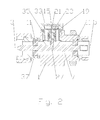
- Figure 4 is a cut-away side schematic view of a surge suppression insert of the first embodiment.
- the surge suppressor body 1 is formed as an in-line assembly dimensioned for a desired co-axial cable or transmission line with a first connection end 3 and a second connection end 5 adapted to couple with a co-axial cable or other equipment at either end via a desired proprietary or standardized connection interface(s).
- the body 1 has a bore 7 in which an inner conductor 9 is positioned, also extending between the first connection end 3 and the second connection end 5 to similarly couple with a cable inner conductor or other equipment.
- the inner conductor 9 may be positioned coaxial within the bore 7 and isolated from the body 1 by one or more insulator(s) 11.
- a surge suppressor insert mount 13 is formed in a side of the body 1, between the first connection end 3 and the second connection end 5.
- the surge suppressor insert mount 13 is adapted to couple a frequency selective shorting element between the inner conductor 9 and the outer conductor, i.e. the body 1.
- the frequency selective shorting element may be formed as a wound wire inductor 15.
- a first end 17 of the wound wire inductor 15 is connected to a top of a hollow cap 19, for example by insertion into a hole 21 formed in the hollow cap 19 and application of a retaining means such as a screw 23, conductive adhesive, interference fit and or soldering.
- a second end 25 of the wound wire inductor is dimensioned to mate with the inner conductor 9 when the hollow cap 19 is seated within the surge suppression insert mount 13.
- a threaded contact 27 coupled to the second end 25 of the wire wound inductor may be adapted to thread into a threaded hole 29 in the inner conductor 9.
- the wire used to form the wire wound inductor 15 preferably has a cross sectional area selected to have adequate current carrying capacity for handling the expected magnitude of the current surges the surge suppressor is configured to couple to the outer conductor and or ground.
- the present inventors have recognized that forming the wound wire inductor 1 5 from wire, rather than machining or stamping the inductor has several advantages.
- a higher level of inductance can be achieved, relative to a stamped or machined inductor of the same size, because a minimum spacing required for stamping or cutting tools is eliminated when an insulating coating is applied to the wire before winding the inductor with the adjacent coils in contact with each other.
- the overall size requirements of the inductor for a given inductance is reduced.
- wire winding equipment is relatively simple to configure for a desired inductor coil diameter and length, allowing cost effective production of a wide range of different inductors with inductances selected in combination with any straight portion(s) of the wire wound inductor coil 15 for specific frequency bands.
- the inductance and parasitic capacitance characteristics of the wire wound inductor may be adapted so that the self resonance frequency is positioned at the center of the desired frequency band.
- the insertion loss represented by the presence of the surge suppressor along the coaxial cable may be minimized within the desired frequency band.
- the self resonance frequency characteristic of the wire wound inductor reduces the extent of a linear portion needed to avail the surge suppressor insert of broadband characteristics, for example as disclosed in Aleksa et al., allowing a significant reduction in the overall size requirements for a surge suppressor according to the invention.
- the linear portion(s) may be accommodated by extending the height of the hollow cap 19.
- Additional tuning of the wire wound inductor 15 impedance characteristics may be applied by adjusting the dielectric value of the material around which the inductor is wound and or that may be inserted between the adjacent individual coils.
- a core material with a specific dielectric value may be applied and or the wire wound inductor may be fully encapsulated in a dielectric, for example as shown in Figure 3.
- an encapsulated wire wound inductor 15, hollow cap 19 and threaded contact 27, may be pre-assembled, to form an integral surge suppression insert 31.
- the surge suppressor insert 31 provides a ready to install assembly that minimizes the chance for damage or loss of loose components prior to installation.
- the hollow cap 19 may be held in place by a retaining cover 33 which threads into the body 1, biasing the hollow cap 19 into secure contact with the body 1.
- the retaining cap 19 may also include an environmental seal 35, such as an o-ring, to prevent moisture migration into the body 1 and thereby into the connected coaxial cables and or equipment.
- a mounting point such as a threaded hole, useful for mounting the surge suppressor to a desired location and or attaching a ground lead may also be formed in the body 1.
- surge suppressor insert 31 has been demonstrated for use with a dedicated body 1, it should also be appreciated that the surge suppressor insert 31 may be easily adapted for use with existing surge suppressor bodies originally supplied with other forms of surge suppression elements, such as quarter wave stubs and or helically machined inductor/stub combinations.
- the body 1 may be formed to receive a retainer element 37 that includes the first connection end 3.
- the retainer element 37 allows the inner conductor 9 and associated insulator(s) 11 to be initially assembled and or exchanged and then securely retains the components in place.
- the retainer element 37 may be coupled to the body, for example, via mating threads and or an interference fit.
- the retainer element 37 may be omitted and the inner conductor 9 mounted within the body by press fitting or injection molding the insulator(s) 11, about the pre-positioned inner conductor 9, within the bore 7.
- the present invention represents a significant improvement in size requirements, ease of use, manufacturing and cost efficiency.
- the overall materials requirements, machining operations and total number of discrete components are reduced.
- the readily exchangeable surge suppression insert(s) 31 according to the invention may be cost effectively manufactured for a wide range of different frequency bands.
- surge suppressors according to the invention for specific frequency bands may be quickly assembled for on-demand delivery with minimal lead time, eliminating the need for large stocks of pre-assembled frequency band specific surge suppressor inventory.
- the surge suppression insert 31 may be easily exchanged by the user without disturbing connections to surrounding equipment.
Landscapes
- Emergency Protection Circuit Devices (AREA)
- Waveguides (AREA)
- Coils Or Transformers For Communication (AREA)
Applications Claiming Priority (1)
| Application Number | Priority Date | Filing Date | Title |
|---|---|---|---|
| US11/163,780 US20070097583A1 (en) | 2005-10-31 | 2005-10-31 | Tuned Coil Coaxial Surge Suppressor |
Publications (1)
| Publication Number | Publication Date |
|---|---|
| EP1780840A2 true EP1780840A2 (de) | 2007-05-02 |
Family
ID=37635625
Family Applications (1)
| Application Number | Title | Priority Date | Filing Date |
|---|---|---|---|
| EP06122007A Withdrawn EP1780840A2 (de) | 2005-10-31 | 2006-10-10 | Überspannungsunterdrücker mit abgestimmter Spule |
Country Status (7)
| Country | Link |
|---|---|
| US (1) | US20070097583A1 (de) |
| EP (1) | EP1780840A2 (de) |
| JP (1) | JP2007135393A (de) |
| CN (1) | CN1967735A (de) |
| BR (1) | BRPI0604335A (de) |
| CA (1) | CA2564447A1 (de) |
| MX (1) | MXPA06012438A (de) |
Families Citing this family (19)
| Publication number | Priority date | Publication date | Assignee | Title |
|---|---|---|---|---|
| WO2009052517A2 (en) * | 2007-10-18 | 2009-04-23 | Polyphaser Corporation | Surge suppression device having one or more rings |
| US8134818B2 (en) * | 2008-04-08 | 2012-03-13 | John Mezzalingua Associates, Inc. | Quarter wave stub surge suppressor with coupled pins |
| WO2009142657A1 (en) * | 2008-05-19 | 2009-11-26 | Polyphaser Corporation | Dc and rf pass broadband surge suppressor |
| US20110235229A1 (en) * | 2010-03-26 | 2011-09-29 | Nguyen Eric H | Ethernet surge protector |
| CA2798891C (en) | 2010-05-11 | 2016-04-12 | Transtector Systems, Inc. | Dc pass rf protector having a surge suppression module |
| US8611062B2 (en) | 2010-05-13 | 2013-12-17 | Transtector Systems, Inc. | Surge current sensor and surge protection system including the same |
| US8976500B2 (en) | 2010-05-26 | 2015-03-10 | Transtector Systems, Inc. | DC block RF coaxial devices |
| KR100996198B1 (ko) | 2010-06-23 | 2010-11-23 | 김선호 | 서지 보호기 및 서지 보호 소자의 제조 방법 |
| US8730637B2 (en) | 2010-12-17 | 2014-05-20 | Transtector Systems, Inc. | Surge protection devices that fail as an open circuit |
| US9054514B2 (en) | 2012-02-10 | 2015-06-09 | Transtector Systems, Inc. | Reduced let through voltage transient protection or suppression circuit |
| US9048662B2 (en) | 2012-03-19 | 2015-06-02 | Transtector Systems, Inc. | DC power surge protector |
| US9190837B2 (en) | 2012-05-03 | 2015-11-17 | Transtector Systems, Inc. | Rigid flex electromagnetic pulse protection device |
| US9124093B2 (en) | 2012-09-21 | 2015-09-01 | Transtector Systems, Inc. | Rail surge voltage protector with fail disconnect |
| US9767957B2 (en) * | 2013-08-12 | 2017-09-19 | Taiwan Semiconductor Manufacturing Co., Ltd. | Method of manufacturing a tunable three dimensional inductor |
| CN104410056A (zh) * | 2014-11-24 | 2015-03-11 | 孙巍巍 | 一种新型装配式电涌保护器 |
| US9912104B2 (en) | 2017-04-18 | 2018-03-06 | Honeywell Federal Maunfacturing and Technologies, LLC | Lightning arrestor connector with mesh dielectric structure |
| CN112086258A (zh) * | 2020-09-09 | 2020-12-15 | 中铁科学研究院有限公司成都分公司 | 感抗式低压浪涌保护装置 |
| US12567707B2 (en) * | 2021-11-22 | 2026-03-03 | Corning Optical Communications Rf Llc | Devices, assemblies, and methods for terminating coaxial radiofrequency ports |
| GB2630315A (en) * | 2023-05-23 | 2024-11-27 | Technetix Bv | Cable network power unit for surge protector release |
Family Cites Families (27)
| Publication number | Priority date | Publication date | Assignee | Title |
|---|---|---|---|---|
| US3289117A (en) * | 1964-03-23 | 1966-11-29 | Sylvania Electric Prod | Surge arrestor utilizing quarter wave stubs |
| US3750053A (en) * | 1972-04-24 | 1973-07-31 | Plessey Inc | Coaxial transmission line rf switch |
| US4236188A (en) * | 1979-01-15 | 1980-11-25 | The United States Of America As Represented By The Secretary Of The Army | Coaxial terminal protection device with disposable cartridge |
| US4262317A (en) * | 1979-03-22 | 1981-04-14 | Reliable Electric Company | Line protector for a communications circuit |
| US4359764A (en) * | 1980-04-08 | 1982-11-16 | Block Roger R | Connector for electromagnetic impulse suppression |
| US4409637A (en) * | 1980-04-08 | 1983-10-11 | Block Roger R | Connector for electromagnetic impulse suppression |
| FR2527846A1 (fr) * | 1982-05-28 | 1983-12-02 | Labo Electronique Physique | Coupleur directionnel hyperfrequence a quatre lignes de transmission et circuit repartiteur de puissance passif realise de facon similaire |
| US4554608A (en) * | 1982-11-15 | 1985-11-19 | Block Roger R | Connector for electromagnetic impulse suppression |
| US4584624A (en) * | 1984-12-10 | 1986-04-22 | Northern Telecom Limited | Station protector for telecommunications systems |
| US4701825A (en) * | 1986-04-07 | 1987-10-20 | Tii Industries, Inc. | Line protector |
| US5053910A (en) * | 1989-10-16 | 1991-10-01 | Perma Power Electronics, Inc. | Surge suppressor for coaxial transmission line |
| AU671565B2 (en) * | 1993-10-07 | 1996-08-29 | Andrew Corporation | Surge protector connector |
| US5953195A (en) * | 1997-02-26 | 1999-09-14 | Reltec Corporation | Coaxial protector |
| US5745328A (en) * | 1997-03-03 | 1998-04-28 | Watkins-Johnson Company | Electromagnetic impulse suppression curcuit |
| US6061223A (en) * | 1997-10-14 | 2000-05-09 | Polyphaser Corporation | Surge suppressor device |
| AU740311B2 (en) * | 1998-02-17 | 2001-11-01 | Huber & Suhner Ag | EMP - charge eliminator |
| DE19936869C1 (de) * | 1999-08-05 | 2001-03-08 | Spinner Gmbh Elektrotech | Koaxialer Überspannungsableiter |
| US6294740B1 (en) * | 1999-09-20 | 2001-09-25 | Andrew Corporation | Spring clip for a gas tube surge arrestor |
| US6452773B1 (en) * | 2000-03-21 | 2002-09-17 | Andrew Corporation | Broadband shorted stub surge protector |
| US6636407B1 (en) * | 2000-09-13 | 2003-10-21 | Andrew Corporation | Broadband surge protector for RF/DC carrying conductor |
| ATE377859T1 (de) * | 2000-10-25 | 2007-11-15 | Huber+Suhner Ag | Störschutzfilter- und blitzstromableiter- einrichtung |
| US6636408B2 (en) * | 2001-03-26 | 2003-10-21 | Marconi Communications, Inc. | Coaxial transmission line surge protector assembly with an integral fuse link |
| WO2002103875A1 (en) * | 2001-06-15 | 2002-12-27 | Kauffman George M | Protective device |
| US6721155B2 (en) * | 2001-08-23 | 2004-04-13 | Andrew Corp. | Broadband surge protector with stub DC injection |
| US6785110B2 (en) * | 2001-10-12 | 2004-08-31 | Polyphaser Corporation | Rf surge protection device |
| US6688916B1 (en) * | 2002-12-23 | 2004-02-10 | Chun Te Lee | Signal connector having function of abrupt wave protection |
| US7170728B2 (en) * | 2005-01-03 | 2007-01-30 | Huber+Suhner Ag | Surge suppressor with increased surge current capability |
-
2005
- 2005-10-31 US US11/163,780 patent/US20070097583A1/en not_active Abandoned
-
2006
- 2006-10-10 EP EP06122007A patent/EP1780840A2/de not_active Withdrawn
- 2006-10-16 CA CA002564447A patent/CA2564447A1/en not_active Abandoned
- 2006-10-24 BR BRPI0604335-6A patent/BRPI0604335A/pt not_active Application Discontinuation
- 2006-10-26 MX MXPA06012438A patent/MXPA06012438A/es not_active Application Discontinuation
- 2006-10-31 JP JP2006295222A patent/JP2007135393A/ja not_active Withdrawn
- 2006-10-31 CN CNA2006101366097A patent/CN1967735A/zh active Pending
Also Published As
| Publication number | Publication date |
|---|---|
| MXPA06012438A (es) | 2007-04-30 |
| US20070097583A1 (en) | 2007-05-03 |
| JP2007135393A (ja) | 2007-05-31 |
| CN1967735A (zh) | 2007-05-23 |
| CA2564447A1 (en) | 2007-04-30 |
| BRPI0604335A (pt) | 2007-08-21 |
Similar Documents
| Publication | Publication Date | Title |
|---|---|---|
| EP1780840A2 (de) | Überspannungsunterdrücker mit abgestimmter Spule | |
| US7349191B2 (en) | Offset planar coil coaxial surge suppressor | |
| EP2088652B1 (de) | Feinabscheider mit niedrigem Bypass | |
| US7609502B2 (en) | Protective device | |
| US6944005B2 (en) | Surge protected coaxial termination | |
| US6754060B2 (en) | Protective device | |
| EP1947661A1 (de) | In-line Kondensatoranordnung mit ineinander verschränkten Elektrodenoberflächen | |
| MXPA05004088A (es) | Arreglo de acoplador de datos para comunicaciones en linea de energia. | |
| EP1137095A2 (de) | Überspannungschutz für Breitband-Anpassungszweig | |
| US7092230B2 (en) | Interference filter and lightning conductor device | |
| US7483251B2 (en) | Multiple planar inductive loop surge suppressor | |
| EP1772931A2 (de) | Vielfach planare Induktivität Koaxial-Überspannungsableiter | |
| US6094109A (en) | Power takeoff inductor | |
| JP7005113B2 (ja) | 同軸避雷器 |
Legal Events
| Date | Code | Title | Description |
|---|---|---|---|
| PUAI | Public reference made under article 153(3) epc to a published international application that has entered the european phase |
Free format text: ORIGINAL CODE: 0009012 |
|
| AK | Designated contracting states |
Kind code of ref document: A2 Designated state(s): AT BE BG CH CY CZ DE DK EE ES FI FR GB GR HU IE IS IT LI LT LU LV MC NL PL PT RO SE SI SK TR |
|
| AX | Request for extension of the european patent |
Extension state: AL BA HR MK YU |
|
| STAA | Information on the status of an ep patent application or granted ep patent |
Free format text: STATUS: THE APPLICATION IS DEEMED TO BE WITHDRAWN |
|
| 18D | Application deemed to be withdrawn |
Effective date: 20100504 |