EP1780708A2 - Electronic apparatus and electronic apparatus control method - Google Patents
Electronic apparatus and electronic apparatus control method Download PDFInfo
- Publication number
- EP1780708A2 EP1780708A2 EP06122853A EP06122853A EP1780708A2 EP 1780708 A2 EP1780708 A2 EP 1780708A2 EP 06122853 A EP06122853 A EP 06122853A EP 06122853 A EP06122853 A EP 06122853A EP 1780708 A2 EP1780708 A2 EP 1780708A2
- Authority
- EP
- European Patent Office
- Prior art keywords
- electronic apparatus
- recording medium
- detection data
- acceleration
- detection
- Prior art date
- Legal status (The legal status is an assumption and is not a legal conclusion. Google has not performed a legal analysis and makes no representation as to the accuracy of the status listed.)
- Granted
Links
Images



Classifications
-
- G—PHYSICS
- G11—INFORMATION STORAGE
- G11B—INFORMATION STORAGE BASED ON RELATIVE MOVEMENT BETWEEN RECORD CARRIER AND TRANSDUCER
- G11B19/00—Driving, starting, stopping record carriers not specifically of filamentary or web form, or of supports therefor; Control thereof; Control of operating function ; Driving both disc and head
- G11B19/02—Control of operating function, e.g. switching from recording to reproducing
- G11B19/04—Arrangements for preventing, inhibiting, or warning against double recording on the same blank or against other recording or reproducing malfunctions
-
- G—PHYSICS
- G06—COMPUTING OR CALCULATING; COUNTING
- G06F—ELECTRIC DIGITAL DATA PROCESSING
- G06F15/00—Digital computers in general; Data processing equipment in general
-
- G—PHYSICS
- G06—COMPUTING OR CALCULATING; COUNTING
- G06F—ELECTRIC DIGITAL DATA PROCESSING
- G06F9/00—Arrangements for program control, e.g. control units
-
- G—PHYSICS
- G11—INFORMATION STORAGE
- G11B—INFORMATION STORAGE BASED ON RELATIVE MOVEMENT BETWEEN RECORD CARRIER AND TRANSDUCER
- G11B19/00—Driving, starting, stopping record carriers not specifically of filamentary or web form, or of supports therefor; Control thereof; Control of operating function ; Driving both disc and head
- G11B19/20—Driving; Starting; Stopping; Control thereof
-
- G—PHYSICS
- G11—INFORMATION STORAGE
- G11B—INFORMATION STORAGE BASED ON RELATIVE MOVEMENT BETWEEN RECORD CARRIER AND TRANSDUCER
- G11B21/00—Head arrangements not specific to the method of recording or reproducing
- G11B21/02—Driving or moving of heads
- G11B21/12—Raising and lowering; Back-spacing or forward-spacing along track; Returning to starting position otherwise than during transducing operation
Definitions
- the present invention relates to an electronic apparatus including an acceleration sensor for drop detection and an electronic apparatus control method.
- the HDD is mounted on a portable electronic apparatus such as a portable music player.
- the portable electronic apparatus mounted with the HDD includes an acceleration sensor for drop detection and performs an operation for retracting a head of the HDD when the acceleration censor detects a drop start state (see, for example, JP-A-2005-11474 ).
- the location of failure is estimated with reference to a state of use or the like of the portable electronic apparatus by a user.
- the state of use or the like alone is often insufficient as information.
- an electronic apparatus including: a recording unit configured to access a recording medium using a head; an acceleration sensor that detects acceleration generated in the electronic apparatus; and a control unit configured to write, in the recording medium or a predetermined memory, detection data indicating a result of the detection by the acceleration sensor or a state of the electronic apparatus detected on the basis of the detection result and retracting, when the detection result satisfies a drop condition for the electronic apparatus defined in advance, the head of the recording unit to a predetermined retraction position.
- an electronic apparatus control method for controlling a portable electronic apparatus including recording means for accessing a recording medium using a head and an acceleration sensor that detects acceleration.
- the electronic apparatus control method includes: a first step of generating detection data indicating a result of the detection by the acceleration sensor or a state of the electronic apparatus detected on the basis of the detection result; a second step of writing the detection data generated in the first step in a predetermined memory; and a third step of retracting, when the detection result satisfies a drop condition for the electronic apparatus defined in advance, the head of the recording means to a predetermined retraction position.
- an electronic apparatus and an electronic apparatus control method that are capable of easily specifying a cause of failure and a location of failure and provide an electronic apparatus and an electronic apparatus control method that are capable of easily specifying a location of failure.
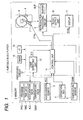
- Fig. 1 is an overall diagram of a portable music player 1 that is an example of an electronic apparatus according to an embodiment of the invention.
- the portable music player 1 includes, for example, a memory 2, an acceleration sensor 3, an operation key 4, a temperature sensor 5, a recording disk 6, a header 7, a reproduction processing circuit 9, an audio output unit 10, a display 11, a processing circuit 12, a timer 15, and an interface 16.
- the memory 2 is an example of a predetermined memory according to the embodiment of the invention.
- the temperature sensor 5 is an example of a temperature sensor according to the embodiment of the invention.
- the acceleration sensor 3 is an example of an acceleration sensor according to the embodiment of the invention.
- the processing circuit 12 is an example of a control unit or control means according to the embodiment of the invention.
- the recording disk 6 is an example of a recording unit or recording means according to the embodiment of the invention.
- the head 7 is an example of a head according to the embodiment of the invention.
- the memory 2 stores a program PRG, time data TIME, acceleration data ACC, and temperature data TEMP.
- the time data TIME, the acceleration data ACC, and the temperature data TEMP are written in the memory 2 according to operations of the processing circuit 12 described later.
- Detection data such as the time data TIME, the acceleration data ACC, and the temperature data TEMP written in the memory 2 are read out at the time of repair of the portable music player 1 and used for specifying a cause of failure of the portable music player 1.
- the acceleration sensor 3 is disposed in a housing of the portable music player 1.
- the acceleration sensor 3 detects accelerations in three axial directions (X, Y, and Z direction) generated in the portable music player 1 and outputs acceleration data indicating the accelerations to a control unit 14.
- the control unit 14 When at least the acceleration in one axial direction of the accelerations in the three axial directions exceeds a predetermined level, the control unit 14 writes detection data in the memory 2.
- the control unit 14 may write detection data in the memory 2 when combined acceleration of the accelerations in the three axial directions exceeds the predetermined level.
- the operation key 4 is constituted by plural keys disposed on the surface of the housing of the portable music player 1.
- the operation key 4 outputs an operation signal corresponding to the operation of a user to the control unit 14 of the processing circuit 12 shown in Fig. 1.
- the temperature sensor 5 is disposed in the housing of the portable music player 1.
- the temperature sensor 5 detects temperature in the housing and outputs temperature data TEMP, which is a result of the detection, to the control unit 4.
- the timer 15 counts time and outputs time data TIME indicating a value of the count to the control unit 14.
- the interface 16 is an interface used for, for example, outputting the detection data stored in the memory 2 to the outside of the portable music player 1.
- the interface 16 outputs detection data such as the time data TIME, the acceleration data ACC, and the temperature data TEMP stored in the memory 2 to the out side of the portable music player 1 at the time of repair of the portable music player 1.
- the display 11 displays a screen corresponding to a display signal S14b from the processing circuit 12.
- the screen is an operation screen such as a music selection screen for selecting content (music data, etc.) to be played, a play screen, or a menu screen.
- the display 11 displays, for example, at the time of repair of the portable music player 1, the detection data such as the time data TIME, the acceleration data ACC, and the temperature data TEMP stored in the memory 2.
- the recording disk 6 is a recording medium such as a hard disk.
- the recording disk 6 records content data such as music data.
- the head 7 reads out the content data from the recording disk 6 and outputs the content data to the reproduction processing circuit 9.
- the head 7 moves from a head retracting section 8 toward the recording disk 6 when the head 7 accesses the recording disk 6.
- the head 7 is held by the head retracting section 8 in a state in which the head 7 does not access the recording disk 6.
- the head 7 since the head 7 is fixed, the head 7 does not damage a recording area of the recording disk 6 even if an impact is applied to the portable music player 1.
- the head 7 reads out, according to control by a not-shown control mechanism, music data from a designated address in the recording disk 6 on the basis of a control signal S14a from the control unit 14 and outputs the music data to the reproduction processing circuit 9.
- the reproduction processing circuit 9 performs reproduction processing for the content data read out from the recording disk 6 by the head 7 and outputs a reproduction signal to an audio output unit 10.
- the reproduction processing circuit 9 includes a buffer memory BUF and stores the content data read out from the recording disk 6 in advance in the buffer memory BUF.
- the reproduction processing circuit 9 reads out the content data from the buffer memory BUF, subjects the content data to reproduction processing, and outputs the content data to the audio output unit 10.
- the processing circuit 12 executes the program PRG read out from the memory 2 and controls operations of the portable music player 1.
- the processing circuit 12 includes a drop detecting unit 13 and the control unit 14.
- the respective components of the processing circuit 12 may be realized as electronic circuits, respectively or may be realized by a CPU (Central Processing Unit) realizing the program PRG read out from the memory 2.
- a CPU Central Processing Unit
- the drop detecting unit 13 judges, on the basis of the acceleration data ACC inputted from the acceleration sensor 3, whether the portable music player 1 has dropped. When it is judged that the portable music player 1 has dropped, the drop detecting unit 13 outputs a drop detection signal S13 to the control unit 14 shown in Fig. 1.
- the drop detecting unit 13 outputs, for example, when combined acceleration of accelerations in the three axial directions indicated by the acceleration data ACC exceeds the predetermined level, the drop detection signal S13, which indicates that the portable music player 1 has dropped, to the control unit 14.
- the control unit 14 shown in Fig. 1 performs predetermined processing on the basis of an operation signal inputted from the operation key 4.
- the control unit 14 performs control of an operation screen displayed on the display 11, readout control for music data from the recording disk 6 by the head 7, processing for writing the detection data such as the time data TIME, the acceleration data ACC, and the temperature data TEMP in the memory 2, and the like.
- the control unit 14 performs processing for reading out, for example, when a predetermined command defined in advance is inputted via the operation unit 4, the detection data such as the time data TIME, the acceleration data ACC, and the temperature data TEMP stored in the memory 2 from the memory 2 and displaying the detection data on the display 11 or outputting the detection data to the outside from the interface 16.
- the detection data such as the time data TIME, the acceleration data ACC, and the temperature data TEMP stored in the memory 2 from the memory 2 and displaying the detection data on the display 11 or outputting the detection data to the outside from the interface 16.
- the control unit 14 retracts the head 7 to the head retracting section 18 when the drop detection signal S13, which indicates that the portable music player 1 has dropped, is inputted from the drop detecting unit 13.
- Fig. 2 is a flowchart for explaining the operation example.
- the control unit 14 judges whether the head 7 is accessing the recording disk 6. When the head 7 is accessing the recording disk 6, the control unit 14 proceeds to step ST3. When the head 7 is not accessing the recording disk 6, the control unit 14 proceeds to step ST2.
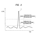
- the control unit 14 sets "th1" shown in Fig. 3 as a threshold used for judgment on whether the detection data should be stored in the memory 2.
- the control unit 14 sets "th2" shown in Fig. 3 as the threshold. Note that “th2" is smaller than “th1".
- a threshold smaller than that set when the head 7 is not accessing the recording disk 6 is set. This makes it possible to write, during head access in which the head 7 tends to collide against the recording disk 6 to cause a damage, the detection data in the memory 2 even when acceleration smaller than that at the time when the head 7 is not accessing the recording disk 6 is generated.
- Fig. 4 is a flowchart for explaining the operation example.
- the control unit 14 judges whether the acceleration data ACC is inputted from the acceleration sensor 3. When it is judged that the acceleration data ACC is inputted, the control unit 14 proceeds to step ST12. When it is judged that the acceleration data ACC is not inputted, the control unit 14 repeats the judgment.
- the control unit 14 compares the acceleration data ACC inputted in step ST11 and a predetermined drop condition. When the drop condition is satisfied (e.g., when the acceleration data ACC exceeds the predetermined level), the control unit 14 proceeds to step ST13. When the drop condition is not satisfied, the control unit 14 returns to step ST11.
- the control unit 14 retracts the head 7 to the head retracting section 8 when the head 7 is accessing the recording disk 6.
- the control unit 14 writes (additionally writes), in the memory 2, acceleration data ACC in a fixed period (e.g., three seconds) after the acceleration data ACC is inputted in step ST11 and time data TIME at the time of acquisition of the acceleration data ACC in association with each other as detection data.
- a fixed period e.g., three seconds
- step ST14 the control unit 14 may stores in the memory 2 only maximum acceleration data ACC of the acceleration data ACC in the fixed period after the acceleration data ACC is inputted in step ST11.
- detection data including an entry indicating that acceleration of "65.5G” was generated in the portable music player 1 at "22:45:37 on August 10, 2005” and an entry indicating that acceleration of "72.1G” was generated in the portable music player 1 at "10:08:25 on August 11, 2005” is stored in the memory 2.
- the detection data is read out from the memory 2 and used for specifying a cause (a location) of failure at the time of repair of the portable music player 1.
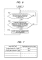
- Fig. 6 is a flowchart for explaining the operation example.
- the control unit 14 judges whether the temperature data TEMP is inputted from the temperature sensor 5. When it is judged that the temperature data TEMP is inputted, the control unit 14 proceeds to step ST22. When it is judged that the temperature data TEMP is not inputted, the control unit 14 repeats the judgment.
- the control unit 14 compares the temperature data inputted in step ST21 and a predetermined condition (a predetermined temperature) and checks whether the predetermined condition is satisfied. When the predetermined condition is satisfied, the control unit 14 proceeds to step ST23. When the predetermined condition is not satisfied, the control unit 14 proceeds to step ST23. When the predetermined condition is not satisfied, the control unit 14 returns to step ST21.
- a predetermined condition a predetermined temperature
- the control unit 14 writes (additionally writes), in the memory 2, the temperature data TEMP inputted in step ST21 and time data TIME at the time of acquisition of the temperature data TEMP in association with each other as detection data.
- detection data including an entry indicating that temperature in the housing of the portable music player 1 rose to "80°C” at "04:08:58 on August 12, 2005” and an entry indicating that temperature in the housing of the portable music player 1 rose to "55°C” at "16:45:06 on August 13, 2005” is stored in the memory 2.
- the detection data is read out from the memory 2 and used for specification of a cause (a location) of failure at the time of repair of the portable music player 1.
- Fig. 8 is a flowchart for explaining the operation example.
- the control unit 14 judges, on the basis of an operation signal from the operation key 4, whether a detection data output command is inputted. When it is judged that the detection data output command is inputted, the control unit 14 proceeds to step ST32. When it is judged that the detection data output command is not inputted, the control unit 14 repeats the judgment.
- the control unit 14 reads out the detection data shown in Fig. 5, Fig. 7, or the like stored in the memory 2.
- the control unit 14 displays the detection data on the display 11 or outputs the detection data to the outside of the portable music player 1 via the interface 16.
- a repairer of the portable music player 1 estimates a cause of failure and a location of failure of the portable music player 1 on the basis of the detection data.
- the acceleration data ACC and the temperature data TEMP satisfies the conditions that can be a cause of failure of the portable music player 1, the acceleration data ACC and the temperature data TEMP are stored in the memory 2 as detection data.
- the invention is not limited to the embodiment described above.
- the portable music player 1 is described as an example of the electronic apparatus according to the embodiment of the invention.
- a type of the electronic apparatus is not specifically limited as long as the electronic apparatus is mounted with an acceleration sensor and includes recording means accessed by a head.
- a cellular phone, a portable or stationary video reproducing apparatus, and the like may be applied other than the portable music player.
- the acceleration data ACC and the temperature data TEMP are written in the memory 2 as the detection data when the predetermined conditions defined in advance are satisfied.
- these data may typically be written in the memory 2.
- the acceleration data ACC and the temperature data TEMP are written in the memory 2 as the detection data in association with the time data TIME.
- the time data TIME does not always have to be written in the memory 2.
- the control unit 14 writes the acceleration data ACC and the temperature data TEMP in the memory 2.
- a state occurring in the portable music player 1 for example, a state in which the portable player 1 has dropped or temperature in the housing of the portable player 1 is higher than the predetermined temperature may be detected and data indicating the state detected may be written in the memory 2.
Landscapes
- Engineering & Computer Science (AREA)
- Theoretical Computer Science (AREA)
- Physics & Mathematics (AREA)
- General Engineering & Computer Science (AREA)
- General Physics & Mathematics (AREA)
- Computer Hardware Design (AREA)
- Software Systems (AREA)
- Signal Processing For Digital Recording And Reproducing (AREA)
- Moving Of Head For Track Selection And Changing (AREA)
- Electrophonic Musical Instruments (AREA)
- Recording Measured Values (AREA)
- Control Of Position Or Direction (AREA)
Abstract
Description
- This application contains subject matter related to
Japanese Patent Application JP 2005-311400 filed in the Japanese Patent Office on October 26, 2005 - The present invention relates to an electronic apparatus including an acceleration sensor for drop detection and an electronic apparatus control method.
- For example, according to a reduction in size of an HDD (Hard Disk Drive7 , the HDD is mounted on a portable electronic apparatus such as a portable music player.
- Since such a portable electronic apparatus is often carried by a user, the portable electronic apparatus is likely to drop. Therefore, the portable electronic apparatus mounted with the HDD includes an acceleration sensor for drop detection and performs an operation for retracting a head of the HDD when the acceleration censor detects a drop start state (see, for example,
JP-A-2005-11474 - When a repairer repairs a broken-down portable electronic apparatus, first, it is necessary to specify a location of failure. The location of failure is estimated with reference to a state of use or the like of the portable electronic apparatus by a user. However, the state of use or the like alone is often insufficient as information.
- Therefore, it is not uncommon for the repairer to spend a long time to specify the location of failure.
- Thus, it is desirable to provide an electronic apparatus and an electronic apparatus control method that are capable of easily specifying a cause of failure and a location of failure.
- According to an embodiment of the invention, there is provided an electronic apparatus including: a recording unit configured to access a recording medium using a head; an acceleration sensor that detects acceleration generated in the electronic apparatus; and a control unit configured to write, in the recording medium or a predetermined memory, detection data indicating a result of the detection by the acceleration sensor or a state of the electronic apparatus detected on the basis of the detection result and retracting, when the detection result satisfies a drop condition for the electronic apparatus defined in advance, the head of the recording unit to a predetermined retraction position.
- According to another embodiment of the invention, there is provided an electronic apparatus control method for controlling a portable electronic apparatus including recording means for accessing a recording medium using a head and an acceleration sensor that detects acceleration. The electronic apparatus control method includes: a first step of generating detection data indicating a result of the detection by the acceleration sensor or a state of the electronic apparatus detected on the basis of the detection result; a second step of writing the detection data generated in the first step in a predetermined memory; and a third step of retracting, when the detection result satisfies a drop condition for the electronic apparatus defined in advance, the head of the recording means to a predetermined retraction position.
- According to an embodiment of the invention, it is possible to provide an electronic apparatus and an electronic apparatus control method that are capable of easily specifying a cause of failure and a location of failure and provide an electronic apparatus and an electronic apparatus control method that are capable of easily specifying a location of failure.
- In the accompanying drawings:
- Fig. 1 is an overall diagram of a portable music player according to an embodiment of the invention;
- Fig. 2 is a flowchart for explaining a method of setting a threshold for X, Y, and Z used by the portable music player to judge whether detection data such as acceleration data ACC should be written in a
memory 2; - Fig. 3 is a graph for explaining a method of setting the thresholds shown in Fig. 2;
- Fig. 4 is a flowchart for explaining operations performed when the portable music player shown in Fig. 1 has dropped;
- Fig. 5 is a table for explaining detection data written in the
memory 2 in the operations shown in Fig. 4; - Fig. 6 is a flowchart for explaining operations in storing temperature data, which indicates a temperature in a housing of the portable music player shown in Fig. 1, in the
memory 2 as detection data; - Fig. 7 is a table for explaining the detection data written in the
memory 2 in the operations shown in Fig. 6; and - Fig. 8 is a flowchart for explaining operations in reading out the detection data stored in the
memory 2 when the portable music player shown in Fig. 1 is repaired. - An embodiment of the invention will be hereinafter explained with reference to the drawings.
- Fig. 1 is an overall diagram of a portable music player 1 that is an example of an electronic apparatus according to an embodiment of the invention.
- As shown in the figure, the portable music player 1 includes, for example, a
memory 2, anacceleration sensor 3, an operation key 4, atemperature sensor 5, arecording disk 6, aheader 7, areproduction processing circuit 9, anaudio output unit 10, a display 11, aprocessing circuit 12, atimer 15, and aninterface 16. - The
memory 2 is an example of a predetermined memory according to the embodiment of the invention. Thetemperature sensor 5 is an example of a temperature sensor according to the embodiment of the invention. Theacceleration sensor 3 is an example of an acceleration sensor according to the embodiment of the invention. Theprocessing circuit 12 is an example of a control unit or control means according to the embodiment of the invention. Therecording disk 6 is an example of a recording unit or recording means according to the embodiment of the invention. Thehead 7 is an example of a head according to the embodiment of the invention. - As shown in Fig. 1, the
memory 2 stores a program PRG, time data TIME, acceleration data ACC, and temperature data TEMP. - The time data TIME, the acceleration data ACC, and the temperature data TEMP are written in the
memory 2 according to operations of theprocessing circuit 12 described later. - Detection data such as the time data TIME, the acceleration data ACC, and the temperature data TEMP written in the
memory 2 are read out at the time of repair of the portable music player 1 and used for specifying a cause of failure of the portable music player 1. - The
acceleration sensor 3 is disposed in a housing of the portable music player 1. Theacceleration sensor 3 detects accelerations in three axial directions (X, Y, and Z direction) generated in the portable music player 1 and outputs acceleration data indicating the accelerations to acontrol unit 14. When at least the acceleration in one axial direction of the accelerations in the three axial directions exceeds a predetermined level, thecontrol unit 14 writes detection data in thememory 2. Thecontrol unit 14 may write detection data in thememory 2 when combined acceleration of the accelerations in the three axial directions exceeds the predetermined level. - The operation key 4 is constituted by plural keys disposed on the surface of the housing of the portable music player 1. The operation key 4 outputs an operation signal corresponding to the operation of a user to the
control unit 14 of theprocessing circuit 12 shown in Fig. 1. - The
temperature sensor 5 is disposed in the housing of the portable music player 1. Thetemperature sensor 5 detects temperature in the housing and outputs temperature data TEMP, which is a result of the detection, to the control unit 4. - The
timer 15 counts time and outputs time data TIME indicating a value of the count to thecontrol unit 14. - The
interface 16 is an interface used for, for example, outputting the detection data stored in thememory 2 to the outside of the portable music player 1. - The
interface 16 outputs detection data such as the time data TIME, the acceleration data ACC, and the temperature data TEMP stored in thememory 2 to the out side of the portable music player 1 at the time of repair of the portable music player 1. - The display 11 displays a screen corresponding to a display signal S14b from the
processing circuit 12. The screen is an operation screen such as a music selection screen for selecting content (music data, etc.) to be played, a play screen, or a menu screen. - The display 11 displays, for example, at the time of repair of the portable music player 1, the detection data such as the time data TIME, the acceleration data ACC, and the temperature data TEMP stored in the
memory 2. - The
recording disk 6 is a recording medium such as a hard disk. Therecording disk 6 records content data such as music data. - The
head 7 reads out the content data from therecording disk 6 and outputs the content data to thereproduction processing circuit 9. - The
head 7 moves from ahead retracting section 8 toward therecording disk 6 when thehead 7 accesses therecording disk 6. - The
head 7 is held by thehead retracting section 8 in a state in which thehead 7 does not access therecording disk 6. In thehead retracting section 8, since thehead 7 is fixed, thehead 7 does not damage a recording area of therecording disk 6 even if an impact is applied to the portable music player 1. - The
head 7 reads out, according to control by a not-shown control mechanism, music data from a designated address in therecording disk 6 on the basis of a control signal S14a from thecontrol unit 14 and outputs the music data to thereproduction processing circuit 9. - The
reproduction processing circuit 9 performs reproduction processing for the content data read out from therecording disk 6 by thehead 7 and outputs a reproduction signal to anaudio output unit 10. - The
reproduction processing circuit 9 includes a buffer memory BUF and stores the content data read out from therecording disk 6 in advance in the buffer memory BUF. Thereproduction processing circuit 9 reads out the content data from the buffer memory BUF, subjects the content data to reproduction processing, and outputs the content data to theaudio output unit 10. - The
processing circuit 12 executes the program PRG read out from thememory 2 and controls operations of the portable music player 1. - As shown in Fig. 1, the
processing circuit 12 includes adrop detecting unit 13 and thecontrol unit 14. - The respective components of the
processing circuit 12 may be realized as electronic circuits, respectively or may be realized by a CPU (Central Processing Unit) realizing the program PRG read out from thememory 2. - The
drop detecting unit 13 judges, on the basis of the acceleration data ACC inputted from theacceleration sensor 3, whether the portable music player 1 has dropped. When it is judged that the portable music player 1 has dropped, thedrop detecting unit 13 outputs a drop detection signal S13 to thecontrol unit 14 shown in Fig. 1. - The
drop detecting unit 13 outputs, for example, when combined acceleration of accelerations in the three axial directions indicated by the acceleration data ACC exceeds the predetermined level, the drop detection signal S13, which indicates that the portable music player 1 has dropped, to thecontrol unit 14. - The
control unit 14 shown in Fig. 1 performs predetermined processing on the basis of an operation signal inputted from the operation key 4. - The
control unit 14 performs control of an operation screen displayed on the display 11, readout control for music data from therecording disk 6 by thehead 7, processing for writing the detection data such as the time data TIME, the acceleration data ACC, and the temperature data TEMP in thememory 2, and the like. - The
control unit 14 performs processing for reading out, for example, when a predetermined command defined in advance is inputted via the operation unit 4, the detection data such as the time data TIME, the acceleration data ACC, and the temperature data TEMP stored in thememory 2 from thememory 2 and displaying the detection data on the display 11 or outputting the detection data to the outside from theinterface 16. - The
control unit 14 retracts thehead 7 to the head retracting section 18 when the drop detection signal S13, which indicates that the portable music player 1 has dropped, is inputted from thedrop detecting unit 13. - Examples of operations of the portable music player 1 will be hereinafter explained.
- In the operation example, a method of setting a threshold used by the portable music player 1 to judge whether the detection data such as the acceleration data ACC should be written in the
memory 2 will be explained. - Fig. 2 is a flowchart for explaining the operation example.
- The
control unit 14 judges whether thehead 7 is accessing therecording disk 6. When thehead 7 is accessing therecording disk 6, thecontrol unit 14 proceeds to step ST3. When thehead 7 is not accessing therecording disk 6, thecontrol unit 14 proceeds to step ST2. - The
control unit 14 sets "th1" shown in Fig. 3 as a threshold used for judgment on whether the detection data should be stored in thememory 2. - The
control unit 14 sets "th2" shown in Fig. 3 as the threshold. Note that "th2" is smaller than "th1". - In this embodiment, as described above, when the
head 7 is accessing therecording disk 6, as the threshold used for judgment on whether the detection data should be stored in thememory 2, a threshold smaller than that set when thehead 7 is not accessing therecording disk 6 is set. This makes it possible to write, during head access in which thehead 7 tends to collide against therecording disk 6 to cause a damage, the detection data in thememory 2 even when acceleration smaller than that at the time when thehead 7 is not accessing therecording disk 6 is generated. - In the operation example, operations performed when the portable music player 1 has dropped will be explained.
- Fig. 4 is a flowchart for explaining the operation example.
- The
control unit 14 judges whether the acceleration data ACC is inputted from theacceleration sensor 3. When it is judged that the acceleration data ACC is inputted, thecontrol unit 14 proceeds to step ST12. When it is judged that the acceleration data ACC is not inputted, thecontrol unit 14 repeats the judgment. - The
control unit 14 compares the acceleration data ACC inputted in step ST11 and a predetermined drop condition. When the drop condition is satisfied (e.g., when the acceleration data ACC exceeds the predetermined level), thecontrol unit 14 proceeds to step ST13. When the drop condition is not satisfied, thecontrol unit 14 returns to step ST11. - The
control unit 14 retracts thehead 7 to thehead retracting section 8 when thehead 7 is accessing therecording disk 6. - As shown in Fig. 5, the
control unit 14 writes (additionally writes), in thememory 2, acceleration data ACC in a fixed period (e.g., three seconds) after the acceleration data ACC is inputted in step ST11 and time data TIME at the time of acquisition of the acceleration data ACC in association with each other as detection data. - In step ST14, the
control unit 14 may stores in thememory 2 only maximum acceleration data ACC of the acceleration data ACC in the fixed period after the acceleration data ACC is inputted in step ST11. - In the example shown in Fig. 5, detection data including an entry indicating that acceleration of "65.5G" was generated in the portable music player 1 at "22:45:37 on August 10, 2005" and an entry indicating that acceleration of "72.1G" was generated in the portable music player 1 at "10:08:25 on August 11, 2005" is stored in the
memory 2. - The detection data is read out from the
memory 2 and used for specifying a cause (a location) of failure at the time of repair of the portable music player 1. - In the operation example, operations in storing temperature data, which indicates temperature in the housing of the portable music player 1, in the
memory 2 as detection data will be explained. - Fig. 6 is a flowchart for explaining the operation example.
- The
control unit 14 judges whether the temperature data TEMP is inputted from thetemperature sensor 5. When it is judged that the temperature data TEMP is inputted, thecontrol unit 14 proceeds to step ST22. When it is judged that the temperature data TEMP is not inputted, thecontrol unit 14 repeats the judgment. - The
control unit 14 compares the temperature data inputted in step ST21 and a predetermined condition (a predetermined temperature) and checks whether the predetermined condition is satisfied. When the predetermined condition is satisfied, thecontrol unit 14 proceeds to step ST23. When the predetermined condition is not satisfied, thecontrol unit 14 proceeds to step ST23. When the predetermined condition is not satisfied, thecontrol unit 14 returns to step ST21. - The
control unit 14 writes (additionally writes), in thememory 2, the temperature data TEMP inputted in step ST21 and time data TIME at the time of acquisition of the temperature data TEMP in association with each other as detection data. - In the example shown in Fig. 7, detection data including an entry indicating that temperature in the housing of the portable music player 1 rose to "80°C" at "04:08:58 on August 12, 2005" and an entry indicating that temperature in the housing of the portable music player 1 rose to "55°C" at "16:45:06 on August 13, 2005" is stored in the
memory 2. - The detection data is read out from the
memory 2 and used for specification of a cause (a location) of failure at the time of repair of the portable music player 1. - In the operation example, operations in reading out the detection data stored in the
memory 2, for example, at the time of repair of the portable music player 1 will be explained. - Fig. 8 is a flowchart for explaining the operation example.
- The
control unit 14 judges, on the basis of an operation signal from the operation key 4, whether a detection data output command is inputted. When it is judged that the detection data output command is inputted, thecontrol unit 14 proceeds to step ST32. When it is judged that the detection data output command is not inputted, thecontrol unit 14 repeats the judgment. - The
control unit 14 reads out the detection data shown in Fig. 5, Fig. 7, or the like stored in thememory 2. Thecontrol unit 14 displays the detection data on the display 11 or outputs the detection data to the outside of the portable music player 1 via theinterface 16. - A repairer of the portable music player 1 estimates a cause of failure and a location of failure of the portable music player 1 on the basis of the detection data.
- As explained above, in the portable music player 1, when the acceleration data ACC and the temperature data TEMP satisfies the conditions that can be a cause of failure of the portable music player 1, the acceleration data ACC and the temperature data TEMP are stored in the
memory 2 as detection data. - AT the time of repair of the portable music player 1, by reading out the detection data from the
memory 2, it is possible to estimate a location of failure and a cause of failure of the portable music player 1 on the basis of the detection data. This makes it possible to make repair work for the portable music player 1 efficient. - The invention is not limited to the embodiment described above.
- In the embodiment described above, the portable music player 1 is described as an example of the electronic apparatus according to the embodiment of the invention. However, a type of the electronic apparatus is not specifically limited as long as the electronic apparatus is mounted with an acceleration sensor and includes recording means accessed by a head.
- As the electronic apparatus according to the embodiment of the invention, a cellular phone, a portable or stationary video reproducing apparatus, and the like may be applied other than the portable music player.
- In the embodiment described above, the acceleration data ACC and the temperature data TEMP are written in the
memory 2 as the detection data when the predetermined conditions defined in advance are satisfied. However, these data may typically be written in thememory 2. - In the embodiment described above, the acceleration data ACC and the temperature data TEMP are written in the
memory 2 as the detection data in association with the time data TIME. However, the time data TIME does not always have to be written in thememory 2. - In the embodiment described above, the
control unit 14 writes the acceleration data ACC and the temperature data TEMP in thememory 2. However, a state occurring in the portable music player 1, for example, a state in which the portable player 1 has dropped or temperature in the housing of the portable player 1 is higher than the predetermined temperature may be detected and data indicating the state detected may be written in thememory 2. - It should be understood by those skilled in the art that various modifications, combinations, sub-combinations, and alterations may occur depending on design requirements and other factors insofar as they are within the scope of the appended claims or the equivalents thereof.
Claims (14)
- An electronic apparatus comprising:a recording unit configured to access a recording medium using a head;an acceleration sensor that detects acceleration generated in the electronic apparatus; anda control unit configured to write, in the recording medium or a predetermined memory, detection data indicating a result of the detection by the acceleration sensor or a state of the electronic apparatus detected on the basis of the detection result and retracting, when the detection result satisfies a drop condition for the electronic apparatus defined in advance, the head of the recording unit to a predetermined retraction position.
- An electronic apparatus according to claim 1, further comprising a timer, wherein
the control unit writes the detection data in the recording medium or the predetermined memory in association with a count value of the timer at the time when the detection data is generated. - An electronic apparatus according to claim 1, wherein the control unit writes, on the basis of the detection result of the acceleration sensor, the detection data in the recording medium or the predetermined memory on condition that it is judged that acceleration associated with a state that causes failure of the electronic apparatus is generated in the electronic apparatus.
- An electronic apparatus according to claim 3, wherein the control unit writes, on the basis of the detection result of the acceleration sensor, the detection data in the recording medium or the predetermined memory when the acceleration generated in the electronic apparatus exceeds a predetermined level.
- An electronic apparatus according to claim 4, wherein the acceleration sensor detects accelerations in three axial directions, and
the control unit writes the detection data in the recording medium or the predetermined memory when at least acceleration in one axial direction among the accelerations in the three axial directions detected by the acceleration sensor exceeds the predetermined level. - An electronic apparatus according to claim 4, wherein the control unit lowers, when the head is accessing the recording medium in the recording unit, the predetermined level compared with that at the time when the head is not accessing the recording medium.
- An electronic apparatus according to claim 1, further comprising a temperature sensor, wherein
the control unit writes, in the recording medium or the predetermined memory, data indicating the detection result of the temperature sensor or a state of the electronic apparatus specified on the basis of the detection result. - An electronic apparatus control method for controlling a portable electronic apparatus including recording means for accessing a recording medium using a head and an acceleration sensor that detects acceleration, the electronic apparatus control method comprising the steps of:generating detection data indicating a result of the detection by the acceleration sensor or a state of the electronic apparatus detected on the basis of the detection result;writing the detection data generated in the step of generating detection data in a predetermined memory; andretracting, when the detection result satisfies a drop condition for the electronic apparatus defined in advance, the head of the recording means to a predetermined retraction position.
- An electronic apparatus control method according to claim 8, wherein
the electronic apparatus further includes a timer, and
in the step of writing the detection data in the recording medium or the predetermined memory, the detection data is written in the recording medium or the predetermined memory in association with a count value of the timer at the time when the detection data is generated. - An electronic apparatus control method according to claim 8, wherein, in the electronic apparatus, in the step of writing the detection data in the recording medium or the predetermined memory, on the basis of the detection result of the acceleration sensor, the detection data is written in the recording medium or the predetermined memory on condition that it is judged that acceleration associated with a state that causes failure of the electronic apparatus is generated in the electronic apparatus.
- An electronic apparatus control method according to claim 10, wherein, in the electronic apparatus, on the basis of the detection result of the acceleration sensor, the detection data is written in the recording medium or the predetermined memory when the acceleration generated in the electronic apparatus exceeds a predetermined level.
- An electronic apparatus control method according to claim 11, wherein
the acceleration sensor detects accelerations in three axial directions, and
in the step of retracting the head of the recording means, the detection data is written in the recording medium or the predetermined memory when at least acceleration in one axial direction among the accelerations in the three axial directions detected by the acceleration sensor exceeds the predetermined level. - An electronic apparatus control method according to claim 11, further comprising the step of lowering, when the head is accessing the recording medium in the recording means, the predetermined level compared with that at the time when the head is not accessing the recording medium.
- An electronic apparatus control method according to claim 8, wherein
the electronic apparatus further includes a temperature sensor, and
in the step of writing the detection data in the recording medium or the predetermined memory, data indicating the detection result of the temperature sensor or a state of the electronic apparatus specified on the basis of the detection result is written in the recording medium or the predetermined memory.
Applications Claiming Priority (1)
| Application Number | Priority Date | Filing Date | Title |
|---|---|---|---|
| JP2005311400A JP4438733B2 (en) | 2005-10-26 | 2005-10-26 | Electronic device and electronic device control method |
Publications (3)
| Publication Number | Publication Date |
|---|---|
| EP1780708A2 true EP1780708A2 (en) | 2007-05-02 |
| EP1780708A3 EP1780708A3 (en) | 2008-04-30 |
| EP1780708B1 EP1780708B1 (en) | 2010-07-28 |
Family
ID=37311852
Family Applications (1)
| Application Number | Title | Priority Date | Filing Date |
|---|---|---|---|
| EP06122853A Not-in-force EP1780708B1 (en) | 2005-10-26 | 2006-10-24 | Electronic apparatus and electronic apparatus control method |
Country Status (7)
| Country | Link |
|---|---|
| US (2) | US7930081B2 (en) |
| EP (1) | EP1780708B1 (en) |
| JP (1) | JP4438733B2 (en) |
| KR (1) | KR20070045124A (en) |
| CN (1) | CN1956081B (en) |
| DE (1) | DE602006015756D1 (en) |
| TW (1) | TW200731236A (en) |
Families Citing this family (5)
| Publication number | Priority date | Publication date | Assignee | Title |
|---|---|---|---|---|
| JP2010123216A (en) * | 2008-11-21 | 2010-06-03 | Nec Corp | Magnetic disk device |
| JP4960482B2 (en) * | 2010-06-23 | 2012-06-27 | 株式会社東芝 | Magnetic disk apparatus and parameter adjusting method in the same |
| CN103295275A (en) * | 2012-03-05 | 2013-09-11 | 联想(北京)有限公司 | Method and device for recording work parameters |
| CN105306666A (en) * | 2014-12-26 | 2016-02-03 | 维沃移动通信有限公司 | Control method of mobile terminal and mobile terminal |
| KR102607790B1 (en) | 2018-11-15 | 2023-11-30 | 삼성전자주식회사 | Method for detecting external shocks and electronic device thereof |
Citations (1)
| Publication number | Priority date | Publication date | Assignee | Title |
|---|---|---|---|---|
| US20050141127A1 (en) | 2003-12-26 | 2005-06-30 | Susumu Shimotono | Method, apparatus and program storage device for magnetic disk drive protection |
Family Cites Families (44)
| Publication number | Priority date | Publication date | Assignee | Title |
|---|---|---|---|---|
| US2913171A (en) * | 1954-12-09 | 1959-11-17 | Ibm | Sorter-collator for tape recorded data |
| US3864661A (en) * | 1973-09-10 | 1975-02-04 | Rohe & 0 Scient Corp | Ultrascope |
| US3944979A (en) * | 1974-12-23 | 1976-03-16 | Data Source Corporation | Method and apparatus for illuminating an object bearing indicia |
| DE2818942C2 (en) * | 1978-04-28 | 1986-03-27 | Zellweger Uster Ag, Uster | Method for room monitoring and device for carrying out the method |
| US4215368A (en) * | 1979-03-15 | 1980-07-29 | Rca Corporation | Memory addressing system for automatic setup TV camera system |
| DE3139985A1 (en) * | 1981-07-15 | 1983-02-03 | Bosch Gmbh Robert | METHOD FOR CONTROLLING AUTOMATIC TRANSMISSIONS IN MOTOR VEHICLES |
| US4461401A (en) * | 1981-07-20 | 1984-07-24 | Sasnett Jr Bolling H | Liquid dispenser assembly |
| NZ204355A (en) * | 1982-06-02 | 1986-07-11 | Nat Res Dev | Averaging accelerometer |
| DE3419448A1 (en) * | 1983-05-24 | 1984-11-29 | Canon K.K., Tokio/Tokyo | IMAGE PROCESSING DEVICE |
| JPH071368B2 (en) * | 1984-01-09 | 1995-01-11 | 株式会社東芝 | Document scanning device |
| US4712195A (en) * | 1986-05-09 | 1987-12-08 | Curtis Instruments, Inc. | Solid-state cumulative operations measurement system |
| US4839755A (en) * | 1986-09-05 | 1989-06-13 | Victor Company Of Japan, Ltd. | Rotary head type digital signal reproducing apparatus with different modes and tracking control |
| JPH0288932A (en) * | 1988-09-27 | 1990-03-29 | Matsushita Electric Ind Co Ltd | Impact recording device |
| JPH0288933A (en) * | 1988-09-27 | 1990-03-29 | Matsushita Electric Ind Co Ltd | impact measuring device |
| US5056056A (en) * | 1989-02-02 | 1991-10-08 | Systems Research Laboratories, Inc. | Data recorder including a recirculating non-volatile memory |
| CA2113026A1 (en) * | 1993-01-28 | 1994-07-29 | Paul Michael Hoseit | Methods and apparatus for intrusion detection having improved immunity to false alarms |
| JP2763499B2 (en) * | 1994-11-30 | 1998-06-11 | 株式会社ナムコ | Image synthesizing apparatus and image synthesizing method |
| US5870502A (en) * | 1996-04-08 | 1999-02-09 | The Trustees Of Columbia University In The City Of New York | System and method for a multiresolution transform of digital image information |
| JP3257948B2 (en) * | 1996-04-30 | 2002-02-18 | 松下電器産業株式会社 | Image extraction device |
| JPH11203770A (en) | 1998-01-19 | 1999-07-30 | Sony Corp | Optical disk player |
| US6453266B1 (en) * | 1999-01-29 | 2002-09-17 | International Business Machines Corporation | Peak detecting shock gauge and damage diagnostic for mobile and handheld computers |
| US6758845B1 (en) * | 1999-10-08 | 2004-07-06 | Lumenis Inc. | Automatic firing apparatus and methods for laser skin treatment over large areas |
| JP3980234B2 (en) * | 2000-01-07 | 2007-09-26 | ペンタックス株式会社 | Digital camera |
| JP2002100180A (en) * | 2000-09-22 | 2002-04-05 | Toshiba Corp | Magnetic disk drive |
| US6520013B1 (en) | 2000-10-02 | 2003-02-18 | Apple Computer, Inc. | Method and apparatus for detecting free fall |
| JP2002243754A (en) * | 2001-02-15 | 2002-08-28 | Matsushita Electric Ind Co Ltd | Electronic equipment and impact detection method for detecting the impact received by it |
| US6576511B2 (en) * | 2001-05-02 | 2003-06-10 | Macronix International Co., Ltd. | Method for forming nitride read only memory |
| US6603620B1 (en) * | 2001-05-25 | 2003-08-05 | Western Digital Technologies, Inc. | Mobile device comprising a disk storage system protected by a motion detector |
| US6580574B1 (en) * | 2001-05-25 | 2003-06-17 | Western Digital Technologies, Inc. | Mobile device comprising a disk storage system protected by a pressure-sensitive detector |
| CN1442542A (en) * | 2002-03-05 | 2003-09-17 | 乐金电子(天津)电器有限公司 | Washing machine |
| US6678601B2 (en) * | 2002-05-31 | 2004-01-13 | Valeo Electrical Systems, Inc. | Motor speed-based anti-pinch control apparatus and method with rough road condition detection and compensation |
| JP4128489B2 (en) * | 2003-06-13 | 2008-07-30 | 富士通株式会社 | Shock detection device, disk device, shock detection method, shock detection program |
| JP4333227B2 (en) | 2003-06-20 | 2009-09-16 | ソニー株式会社 | Electronic device and impact mitigation method for electronic device |
| JP2005037300A (en) | 2003-07-17 | 2005-02-10 | Hitachi Metals Ltd | Portable equipment having acceleration history recording function, and acceleration sensor device used for the same |
| JP2005129172A (en) * | 2003-10-24 | 2005-05-19 | Matsushita Electric Ind Co Ltd | Hard disk drive impact protection device |
| JP4352386B2 (en) * | 2003-11-25 | 2009-10-28 | 日立工機株式会社 | centrifuge |
| US7782482B2 (en) * | 2004-02-13 | 2010-08-24 | Seiko Epson Corporation | Color compensation of printing device |
| JP2005241503A (en) | 2004-02-27 | 2005-09-08 | Hitachi Metals Ltd | Acceleration history recording device at time of falling and acceleration sensor device used therefor |
| US7794499B2 (en) * | 2004-06-08 | 2010-09-14 | Theken Disc, L.L.C. | Prosthetic intervertebral spinal disc with integral microprocessor |
| JP2006323664A (en) * | 2005-05-19 | 2006-11-30 | Sony Corp | Electronics |
| JP2006343933A (en) * | 2005-06-08 | 2006-12-21 | Sony Corp | Data processing method, electronic device, and program |
| US8631483B2 (en) * | 2005-06-14 | 2014-01-14 | Texas Instruments Incorporated | Packet processors and packet filter processes, circuits, devices, and systems |
| KR100703164B1 (en) * | 2005-07-12 | 2007-04-06 | 삼성전자주식회사 | Data processing device and control method |
| JP2007042173A (en) * | 2005-08-01 | 2007-02-15 | Sony Corp | Electronic device, data processing method and program |
-
2005
- 2005-10-26 JP JP2005311400A patent/JP4438733B2/en not_active Expired - Fee Related
-
2006
- 2006-10-23 US US11/584,674 patent/US7930081B2/en not_active Expired - Fee Related
- 2006-10-24 TW TW095139184A patent/TW200731236A/en not_active IP Right Cessation
- 2006-10-24 EP EP06122853A patent/EP1780708B1/en not_active Not-in-force
- 2006-10-24 DE DE602006015756T patent/DE602006015756D1/en active Active
- 2006-10-26 KR KR1020060104350A patent/KR20070045124A/en not_active Ceased
- 2006-10-26 CN CN2006101429912A patent/CN1956081B/en not_active Expired - Fee Related
-
2011
- 2011-01-20 US US13/010,546 patent/US9032778B2/en not_active Expired - Fee Related
Patent Citations (1)
| Publication number | Priority date | Publication date | Assignee | Title |
|---|---|---|---|---|
| US20050141127A1 (en) | 2003-12-26 | 2005-06-30 | Susumu Shimotono | Method, apparatus and program storage device for magnetic disk drive protection |
Also Published As
| Publication number | Publication date |
|---|---|
| EP1780708B1 (en) | 2010-07-28 |
| US9032778B2 (en) | 2015-05-19 |
| CN1956081A (en) | 2007-05-02 |
| US20110107814A1 (en) | 2011-05-12 |
| KR20070045124A (en) | 2007-05-02 |
| CN1956081B (en) | 2012-07-18 |
| TW200731236A (en) | 2007-08-16 |
| EP1780708A3 (en) | 2008-04-30 |
| JP4438733B2 (en) | 2010-03-24 |
| US20070110407A1 (en) | 2007-05-17 |
| DE602006015756D1 (en) | 2010-09-09 |
| TWI336467B (en) | 2011-01-21 |
| JP2007122790A (en) | 2007-05-17 |
| US7930081B2 (en) | 2011-04-19 |
Similar Documents
| Publication | Publication Date | Title |
|---|---|---|
| US9354817B2 (en) | Disk storage apparatus and data storage method | |
| US9032778B2 (en) | Electronic apparatus and electronic apparatus control method | |
| US8194033B2 (en) | Reproducing device, setting changing method, and setting changing device | |
| JPWO2005106503A1 (en) | Electronic device and fall detection method | |
| US20060217825A1 (en) | Electronic apparatus and data processing method | |
| JP2006338691A (en) | Hybrid storage and information processing apparatus using the same | |
| US7525750B2 (en) | Head retracting apparatus, storage device, and head retracting method | |
| US7321532B2 (en) | Protection device and method of a read and write medium apparatus | |
| US20060284833A1 (en) | Portable electronic device capable of performing a function according to a sensing result of pressure | |
| US7987317B2 (en) | Data recording device and control method of same | |
| JP2008251129A (en) | Information processing apparatus, information processing method, and computer program | |
| JP2006351118A (en) | Disk drive device, electronic device, and disk control method | |
| US7379260B2 (en) | Control apparatus, storage device, and head retracting method | |
| JP2007335010A (en) | Storage device, head return method, and head return device | |
| EP2124448A1 (en) | Method for playing streaming data, electronic device for performing the same and information storage media for storing the same | |
| US7529056B2 (en) | Control apparatus, storage device, and head retracting method | |
| US20060156024A1 (en) | Systems and methods for disk drive access under changes in environmental parameters | |
| JP2007109355A (en) | Fall detecting method and portable terminal device | |
| JP2007035156A (en) | Data recording apparatus, data recording method, data recording program, and recording medium | |
| JP2010061716A (en) | Information recording device | |
| JP2009272020A (en) | Disk driving device and method for specifying false detection of fall in disk driving device | |
| JP4308116B2 (en) | Data playback device | |
| US20120324165A1 (en) | Memory control device and memory control method | |
| JP2009193612A (en) | Magnetic disk unit | |
| JP2009272019A (en) | Disk driving device and method for testing fall sensor in disk driving device |
Legal Events
| Date | Code | Title | Description |
|---|---|---|---|
| PUAI | Public reference made under article 153(3) epc to a published international application that has entered the european phase |
Free format text: ORIGINAL CODE: 0009012 |
|
| AK | Designated contracting states |
Kind code of ref document: A2 Designated state(s): AT BE BG CH CY CZ DE DK EE ES FI FR GB GR HU IE IS IT LI LT LU LV MC NL PL PT RO SE SI SK TR |
|
| AX | Request for extension of the european patent |
Extension state: AL BA HR MK YU |
|
| PUAL | Search report despatched |
Free format text: ORIGINAL CODE: 0009013 |
|
| AK | Designated contracting states |
Kind code of ref document: A3 Designated state(s): AT BE BG CH CY CZ DE DK EE ES FI FR GB GR HU IE IS IT LI LT LU LV MC NL PL PT RO SE SI SK TR |
|
| AX | Request for extension of the european patent |
Extension state: AL BA HR MK RS |
|
| 17P | Request for examination filed |
Effective date: 20081002 |
|
| 17Q | First examination report despatched |
Effective date: 20081106 |
|
| AKX | Designation fees paid |
Designated state(s): DE FR GB |
|
| GRAP | Despatch of communication of intention to grant a patent |
Free format text: ORIGINAL CODE: EPIDOSNIGR1 |
|
| GRAS | Grant fee paid |
Free format text: ORIGINAL CODE: EPIDOSNIGR3 |
|
| GRAA | (expected) grant |
Free format text: ORIGINAL CODE: 0009210 |
|
| AK | Designated contracting states |
Kind code of ref document: B1 Designated state(s): DE FR GB |
|
| REG | Reference to a national code |
Ref country code: GB Ref legal event code: FG4D |
|
| REF | Corresponds to: |
Ref document number: 602006015756 Country of ref document: DE Date of ref document: 20100909 Kind code of ref document: P |
|
| PLBE | No opposition filed within time limit |
Free format text: ORIGINAL CODE: 0009261 |
|
| STAA | Information on the status of an ep patent application or granted ep patent |
Free format text: STATUS: NO OPPOSITION FILED WITHIN TIME LIMIT |
|
| 26N | No opposition filed |
Effective date: 20110429 |
|
| REG | Reference to a national code |
Ref country code: DE Ref legal event code: R097 Ref document number: 602006015756 Country of ref document: DE Effective date: 20110429 |
|
| REG | Reference to a national code |
Ref country code: GB Ref legal event code: 746 Effective date: 20120703 |
|
| REG | Reference to a national code |
Ref country code: DE Ref legal event code: R084 Ref document number: 602006015756 Country of ref document: DE Effective date: 20120614 |
|
| PGFP | Annual fee paid to national office [announced via postgrant information from national office to epo] |
Ref country code: DE Payment date: 20121023 Year of fee payment: 7 Ref country code: FR Payment date: 20121031 Year of fee payment: 7 |
|
| PGFP | Annual fee paid to national office [announced via postgrant information from national office to epo] |
Ref country code: GB Payment date: 20121019 Year of fee payment: 7 |
|
| GBPC | Gb: european patent ceased through non-payment of renewal fee |
Effective date: 20131024 |
|
| PG25 | Lapsed in a contracting state [announced via postgrant information from national office to epo] |
Ref country code: GB Free format text: LAPSE BECAUSE OF NON-PAYMENT OF DUE FEES Effective date: 20131024 |
|
| REG | Reference to a national code |
Ref country code: DE Ref legal event code: R119 Ref document number: 602006015756 Country of ref document: DE Effective date: 20140501 |
|
| REG | Reference to a national code |
Ref country code: FR Ref legal event code: ST Effective date: 20140630 |
|
| PG25 | Lapsed in a contracting state [announced via postgrant information from national office to epo] |
Ref country code: FR Free format text: LAPSE BECAUSE OF NON-PAYMENT OF DUE FEES Effective date: 20131031 Ref country code: DE Free format text: LAPSE BECAUSE OF NON-PAYMENT OF DUE FEES Effective date: 20140501 |